EP3441665B1 - Module d'éclairage rotatif pour véhicules et dispositif d'éclairage associé pour véhicules - Google Patents
Module d'éclairage rotatif pour véhicules et dispositif d'éclairage associé pour véhicules Download PDFInfo
- Publication number
- EP3441665B1 EP3441665B1 EP17185381.5A EP17185381A EP3441665B1 EP 3441665 B1 EP3441665 B1 EP 3441665B1 EP 17185381 A EP17185381 A EP 17185381A EP 3441665 B1 EP3441665 B1 EP 3441665B1
- Authority
- EP
- European Patent Office
- Prior art keywords
- shaft
- framed support
- light source
- lighting module
- optical unit
- Prior art date
- Legal status (The legal status is an assumption and is not a legal conclusion. Google has not performed a legal analysis and makes no representation as to the accuracy of the status listed.)
- Active
Links
- 230000003287 optical effect Effects 0.000 claims description 24
- 230000005540 biological transmission Effects 0.000 claims description 13
- 238000005096 rolling process Methods 0.000 claims description 5
- 239000007787 solid Substances 0.000 claims description 2
- 238000010168 coupling process Methods 0.000 description 3
- 238000005859 coupling reaction Methods 0.000 description 3
- 230000008878 coupling Effects 0.000 description 2
- 239000000428 dust Substances 0.000 description 2
- XAGFODPZIPBFFR-UHFFFAOYSA-N aluminium Chemical compound [Al] XAGFODPZIPBFFR-UHFFFAOYSA-N 0.000 description 1
- 229910052782 aluminium Inorganic materials 0.000 description 1
- 230000015572 biosynthetic process Effects 0.000 description 1
- 238000010276 construction Methods 0.000 description 1
- 230000006735 deficit Effects 0.000 description 1
- 238000009826 distribution Methods 0.000 description 1
- 238000001746 injection moulding Methods 0.000 description 1
- 229910001234 light alloy Inorganic materials 0.000 description 1
- 238000004519 manufacturing process Methods 0.000 description 1
- 239000000463 material Substances 0.000 description 1
- 230000010355 oscillation Effects 0.000 description 1
- 238000009877 rendering Methods 0.000 description 1
- 239000000243 solution Substances 0.000 description 1
Images


Classifications
-
- F—MECHANICAL ENGINEERING; LIGHTING; HEATING; WEAPONS; BLASTING
- F21—LIGHTING
- F21S—NON-PORTABLE LIGHTING DEVICES; SYSTEMS THEREOF; VEHICLE LIGHTING DEVICES SPECIALLY ADAPTED FOR VEHICLE EXTERIORS
- F21S41/00—Illuminating devices specially adapted for vehicle exteriors, e.g. headlamps
- F21S41/20—Illuminating devices specially adapted for vehicle exteriors, e.g. headlamps characterised by refractors, transparent cover plates, light guides or filters
-
- F—MECHANICAL ENGINEERING; LIGHTING; HEATING; WEAPONS; BLASTING
- F21—LIGHTING
- F21S—NON-PORTABLE LIGHTING DEVICES; SYSTEMS THEREOF; VEHICLE LIGHTING DEVICES SPECIALLY ADAPTED FOR VEHICLE EXTERIORS
- F21S41/00—Illuminating devices specially adapted for vehicle exteriors, e.g. headlamps
- F21S41/10—Illuminating devices specially adapted for vehicle exteriors, e.g. headlamps characterised by the light source
- F21S41/14—Illuminating devices specially adapted for vehicle exteriors, e.g. headlamps characterised by the light source characterised by the type of light source
- F21S41/141—Light emitting diodes [LED]
- F21S41/147—Light emitting diodes [LED] the main emission direction of the LED being angled to the optical axis of the illuminating device
- F21S41/148—Light emitting diodes [LED] the main emission direction of the LED being angled to the optical axis of the illuminating device the main emission direction of the LED being perpendicular to the optical axis
-
- F—MECHANICAL ENGINEERING; LIGHTING; HEATING; WEAPONS; BLASTING
- F21—LIGHTING
- F21S—NON-PORTABLE LIGHTING DEVICES; SYSTEMS THEREOF; VEHICLE LIGHTING DEVICES SPECIALLY ADAPTED FOR VEHICLE EXTERIORS
- F21S41/00—Illuminating devices specially adapted for vehicle exteriors, e.g. headlamps
- F21S41/20—Illuminating devices specially adapted for vehicle exteriors, e.g. headlamps characterised by refractors, transparent cover plates, light guides or filters
- F21S41/29—Attachment thereof
-
- F—MECHANICAL ENGINEERING; LIGHTING; HEATING; WEAPONS; BLASTING
- F21—LIGHTING
- F21S—NON-PORTABLE LIGHTING DEVICES; SYSTEMS THEREOF; VEHICLE LIGHTING DEVICES SPECIALLY ADAPTED FOR VEHICLE EXTERIORS
- F21S41/00—Illuminating devices specially adapted for vehicle exteriors, e.g. headlamps
- F21S41/30—Illuminating devices specially adapted for vehicle exteriors, e.g. headlamps characterised by reflectors
-
- F—MECHANICAL ENGINEERING; LIGHTING; HEATING; WEAPONS; BLASTING
- F21—LIGHTING
- F21S—NON-PORTABLE LIGHTING DEVICES; SYSTEMS THEREOF; VEHICLE LIGHTING DEVICES SPECIALLY ADAPTED FOR VEHICLE EXTERIORS
- F21S41/00—Illuminating devices specially adapted for vehicle exteriors, e.g. headlamps
- F21S41/40—Illuminating devices specially adapted for vehicle exteriors, e.g. headlamps characterised by screens, non-reflecting members, light-shielding members or fixed shades
- F21S41/47—Attachment thereof
-
- F—MECHANICAL ENGINEERING; LIGHTING; HEATING; WEAPONS; BLASTING
- F21—LIGHTING
- F21S—NON-PORTABLE LIGHTING DEVICES; SYSTEMS THEREOF; VEHICLE LIGHTING DEVICES SPECIALLY ADAPTED FOR VEHICLE EXTERIORS
- F21S41/00—Illuminating devices specially adapted for vehicle exteriors, e.g. headlamps
- F21S41/60—Illuminating devices specially adapted for vehicle exteriors, e.g. headlamps characterised by a variable light distribution
- F21S41/63—Illuminating devices specially adapted for vehicle exteriors, e.g. headlamps characterised by a variable light distribution by acting on refractors, filters or transparent cover plates
- F21S41/635—Illuminating devices specially adapted for vehicle exteriors, e.g. headlamps characterised by a variable light distribution by acting on refractors, filters or transparent cover plates by moving refractors, filters or transparent cover plates
-
- F—MECHANICAL ENGINEERING; LIGHTING; HEATING; WEAPONS; BLASTING
- F21—LIGHTING
- F21S—NON-PORTABLE LIGHTING DEVICES; SYSTEMS THEREOF; VEHICLE LIGHTING DEVICES SPECIALLY ADAPTED FOR VEHICLE EXTERIORS
- F21S41/00—Illuminating devices specially adapted for vehicle exteriors, e.g. headlamps
- F21S41/60—Illuminating devices specially adapted for vehicle exteriors, e.g. headlamps characterised by a variable light distribution
- F21S41/65—Illuminating devices specially adapted for vehicle exteriors, e.g. headlamps characterised by a variable light distribution by acting on light sources
- F21S41/657—Illuminating devices specially adapted for vehicle exteriors, e.g. headlamps characterised by a variable light distribution by acting on light sources by moving light sources
-
- F—MECHANICAL ENGINEERING; LIGHTING; HEATING; WEAPONS; BLASTING
- F21—LIGHTING
- F21S—NON-PORTABLE LIGHTING DEVICES; SYSTEMS THEREOF; VEHICLE LIGHTING DEVICES SPECIALLY ADAPTED FOR VEHICLE EXTERIORS
- F21S41/00—Illuminating devices specially adapted for vehicle exteriors, e.g. headlamps
- F21S41/60—Illuminating devices specially adapted for vehicle exteriors, e.g. headlamps characterised by a variable light distribution
- F21S41/67—Illuminating devices specially adapted for vehicle exteriors, e.g. headlamps characterised by a variable light distribution by acting on reflectors
- F21S41/675—Illuminating devices specially adapted for vehicle exteriors, e.g. headlamps characterised by a variable light distribution by acting on reflectors by moving reflectors
-
- F—MECHANICAL ENGINEERING; LIGHTING; HEATING; WEAPONS; BLASTING
- F21—LIGHTING
- F21S—NON-PORTABLE LIGHTING DEVICES; SYSTEMS THEREOF; VEHICLE LIGHTING DEVICES SPECIALLY ADAPTED FOR VEHICLE EXTERIORS
- F21S43/00—Signalling devices specially adapted for vehicle exteriors, e.g. brake lamps, direction indicator lights or reversing lights
- F21S43/40—Signalling devices specially adapted for vehicle exteriors, e.g. brake lamps, direction indicator lights or reversing lights characterised by the combination of reflectors and refractors
-
- F—MECHANICAL ENGINEERING; LIGHTING; HEATING; WEAPONS; BLASTING
- F21—LIGHTING
- F21V—FUNCTIONAL FEATURES OR DETAILS OF LIGHTING DEVICES OR SYSTEMS THEREOF; STRUCTURAL COMBINATIONS OF LIGHTING DEVICES WITH OTHER ARTICLES, NOT OTHERWISE PROVIDED FOR
- F21V23/00—Arrangement of electric circuit elements in or on lighting devices
- F21V23/003—Arrangement of electric circuit elements in or on lighting devices the elements being electronics drivers or controllers for operating the light source, e.g. for a LED array
-
- F—MECHANICAL ENGINEERING; LIGHTING; HEATING; WEAPONS; BLASTING
- F21—LIGHTING
- F21W—INDEXING SCHEME ASSOCIATED WITH SUBCLASSES F21K, F21L, F21S and F21V, RELATING TO USES OR APPLICATIONS OF LIGHTING DEVICES OR SYSTEMS
- F21W2107/00—Use or application of lighting devices on or in particular types of vehicles
- F21W2107/10—Use or application of lighting devices on or in particular types of vehicles for land vehicles
Definitions
- the present invention relates to a rotating lighting module for vehicles and to a lighting device equipped with a plurality (i.e. at least two) of such lighting modules having rotation capabilities, preferably associated with a main non-rotating lighting module, in order to provide selectively a plurality of lighting distributions by means of the same lighting device.
- Lighting devices for vehicles comprising a plurality of individual lighting modules, some of which are provided with rotating elements, like e.g. a rotating reflector, are known in the art.
- EP2902701 and FR3022322A1 disclose a lighting module having a fixed light source consisting of a LED and a rotating support having two opposite faces, one constituting a reflector and the other realizing a second function, e.g. an aspect function; a fixed motor rotates the support with respect to the fixed light source in order to bring selectively the two faces on the front side of the device facing toward the direction of motion of the vehicle.
- the light source is a LED mounted on a printed circuit board and the rotating reflector is pivoting on a couple of opposite coaxial pins, a first of which is idly housed in a through seat provided in the printed circuit board and in a supporting structure thereof, and a second of which is idly housed in a second seat provided in a base of the supporting structure.
- the object of the present invention is to provide a rotating lighting module and a lighting device for vehicles comprising a plurality of such rotating lighting modules, which are of simple and compact construction and assembly, are cost-effective and, at the same time, are highly reliable, are not noising and maintain their optical performances along time.
- reference number 1 indicates as a whole a lighting device consisting, in the non-limiting embodiment shown, in a vehicle headlight assembly, which is only schematically shown from the front, with parts, which are not essential for describing the invention, removed for sake of simplicity.
- the lighting device 1 comprises a generally cup-shaped housing body 2 designed to be mounted on a vehicle, known and not shown for sake of simplicity.
- Housing body 2 is made of synthetic plastic material by injection molding and has a front inlet opening 3 in use facing opposite to the vehicle and toward a forward driving direction FD of the vehicle, indicated by an arrow; the front inlet opening is closed by a transparent cover, normally constituted by a terse lens (i.e. a transparent lens not provided with optical functions), known and not shown (removed) for sake of simplicity .
- the lighting device 1 comprises a stationary main lighting module 4 and a plurality (e.g. at least two or more than two) of secondary lighting modules 5, each rotating around a respective axis, arranged generally vertical.
- the lighting modules 4,5 are arranged side by side within the housing body 2, facing the inlet opening 3 and the rotating lighting modules 5 are arranged within the housing body 2, as it will be seen in greater details herein below, pivoting around respective first axes A1, A2 and A3, arranged all parallel to each other.
- the main lighting module 4 has an optical axis O arranged parallel to the forward march direction FD and along which the light beam generated in use by the lighting module 4 is delivered.
- each rotating lighting module 5 has its own optical axis O1, which may be rotated in use around the respective pivoting axes A1, A2 and A3.
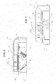
- a rotating lighting module 5 for vehicles according to the invention is shown in an enlarged scale and in details in figures 2 , 3 and 5-7 .
- Each rotating lighting module 5 comprises at least one light source 6, at least one reflector 7 and at least one actuator 8 to rotate the reflector 7 relative to the light source 6 around a first pivoting axis A, in the example shown the axis A1.
- each lighting module 5 further comprises a lens 9, which is assembled angularly rigid with the reflector 7 and forms, together with the reflector 7, a rotating optical unit 10 powered by the actuator 8.
- the at least one light source 6, the actuator 8 and the rotating optical unit 10 are operatively associated with a framed support 11 holding rigid in a fixed position the light source 6 and bearing in idling manner the rotating optical unit 10.
- the light source 6 is borne by a printed circuit board 12, also bearing electronic components 13, known in the art, to control the light source 6.
- the printed circuit board 12 bears more than one light source, e.g. further two or three, to perform different lighting functions.
- the light source 6 is preferably a LED.
- the framed support 11 is formed by a rigid metallic structure, generally C-shaped, e.g. realized in a press-molded, aluminum based, light alloy.
- each lighting module 5 is configured so that the corresponding rotating optical unit 10 is supported in idly manner solely by a bottom portion 14 of the framed support 11 of each module 5.
- the rotating optical unit 10 is self-supporting and is configured ( figures 3,4 ) to form within the corresponding lighting module 5 a first sub-assembly 15, which is completely independent of an upper portion 16 of the framed support 11 bearing the at least one light source 6, in the case in point bearing the whole printed circuit board 12 with the at least one (or more) light source 6 and the electronic components 13.
- the at least one light source 6 with the printed circuit board 12 and the electronic components 13 form within the corresponding lighting module 5 a second sub-assembly 18 supported solely by the upper portion 16 of the framed support 11.
- the first sub-assembly 15 is mechanically disconnected in rotation from the second sub-assembly 18.
- the first sub-assembly 15 ( figures 3,4 ) comprises a rigid box-like structure 19 connecting the reflector 7 with the lens 9, facing to each other, and a shaft 20 having a symmetry axis coinciding with the first axis A (axis A1 in the embodiment shown) ; the shaft 20 is configured such as to project in cantilever fashion from the rigid box-like structure 19, in particular from the bottom thereof, namely on the side thereof facing away from the printed circuit board 12 and the respective sub-assembly 18.
- the shaft 20 is housed entirely within a first through seat 21 ( figures 3 and 5 ) provided in the bottom portion 14 of the framed support 11 and is supported by a first rolling bearing 22 and by a second rolling bearing 23 housed within opposite ends 24,25 of the first through seat 21.
- the rolling bearings 22,23 are coupled idly with the shaft 20 at respective opposite ends 26,27 thereof; accordingly, the shaft 20 with the bearings 22,23 are configured so that the shaft 20 is the sole, unique, single support and rotational guide for the rotating optical unit 10.
- the shaft 20 is of a tubular shape (see figure 5 ), being axially crossed by a second through seat 28 so as to be delimited laterally by an annular wall 29.
- the shaft 20 is configured such as to be elastically deformable in radial direction at least at the opposite ends 26,27 thereof.
- both ends 26, 27 with at least a couple of radial slots 30 extending axially; the radial slots 30 are open-ended at respective terminal edges of the ends 26,27.
- the first sub-assembly 15 further comprises ( figure 5 ) a rod 31 designed to be removably inserted axially within the second through seat 28 in order to prevent, when inserted, any radial deformation of the shaft 20 and so rendering it completely rigid.
- the rod 31 is threaded and is screwed into the seat 28.
- Another way of coupling e.g. a snap-coupling, may be used in alternative, even if the screw coupling is safer and is preferred.
- the shaft 20 has to have in axial direction a length comparable with the height of the box-like rigid structure 19 in the same axial direction.
- the length of shaft 20 is at least of the same order of magnitude of the height of the box-structure 19 and preferably that the two differ for less than the 20%.
- the shaft 20 has its side wall 29 provided radially outwards with at least one axial groove 32 (preferably at least three axial grooves 32 angularly spaced at 120° to each other).
- the at least one axial grove 32 is engaged by a first transmission wheel 33 ( figure 5 - a toothed wheel or gear 33, in the embodiment shown) fitted axially upon shaft 20; in fact, in the preferred embodiment shown, the bottom portion 14 of the framed support 11 is shaped as a box forming externally on the framed support 11 an internally hollow plate-like base 34 ( figure 2 ).
- the rotating optical unit 10 projects axially upwards in cantilever fashion from the bottom portion 14 of the framed support 11, namely from the internally hollow plate-like base 34, towards the upper portion 16 of the framed support 11, remaining spaced apart from the upper portion 16
- the actuator 8 is carried externally by the bottom portion 14 of the framed support 11, in particular by the internally hollow plate-like base 34, on the side opposite to the rotating optical unit 10; the actuator 8 is moreover mechanically connected to the transmission wheel 33 by transmission elements, e.g. other two toothed gears 35 ( figure 5 ); the transmission wheel 33 and the transmission elements 35 are housed idly within the plate-like base 34 formed by the bottom portion 14 of the framed support 11.
- transmission elements e.g. other two toothed gears 35 ( figure 5 )
- the transmission wheel 33 and the transmission elements 35 are housed idly within the plate-like base 34 formed by the bottom portion 14 of the framed support 11.
- the framed support 11 is generally C-shaped and, according to a further feature of the invention, is formed ( figure 2 ) by two specular-symmetrical half-shells 36, one of which is better shown alone in figure 3 ) mechanically coupled together side by side at a plane parallel to the half-shells 36, i.e. parallel to their laying plane, and containing the first axis A, in the example shown axis A1.
- the two half-shells 36 are coupled together in a removable manner, so as to be separable, in the embodiment shown by means of lateral screws 37.
- Each half-shell comprises ( figure 3 ): a L-shaped portion 38 configured as a solid, profiled element having a double T shape in cross-section and defining with its opposite wings, when the two half-shells 36 are coupled, the upper portion 16 and a middle portion 39 of the framed support 11; and a bottom cup-shaped section 40 configured such as, when the two half-shells 36 are coupled, extends parallel to and facing with the upper portion 16 of the framed support 11, to which is connected by the middle portion 39.
- the bottom cup-shaped sections 40 of the two half-shells 36 form, when the latter are coupled together, the plate-like hollow base 34 defining/delimiting at least part of the bottom portion 14 of the framed support 11.
- each rotating lighting module 5 is extremely easy.
- the rotating optical unit 10 is guided with precision and without the risk of oscillations/vibrations by the combination of the partially hollow, rigid and metallic framed support 11 with the projecting shaft 20 borne rigid with the rotating optical unit 10 and with the supporting rolling bearing 22,23 thereof arranged at the opposite ends 26,27 of the shaft 20.
- the rotating optical unit 10 is mechanically completely separated from the printed circuit board 12 as far as its rotation capability is concerned, both wear of the rotation seat through the printed circuit board (which exists no more according to the invention) and the formation of dust due to wear are avoided, so impeding both the possible generation of noise and the possible impairment of the optical performances of the lighting module in use.
Claims (7)
- Module d'éclairage rotatif (5) pour véhicules, comprenant au moins une source de lumière (6), au moins un réflecteur (7) et au moins un actionneur (8) pour faire tourner le réflecteur par rapport à la source de lumière autour d'un premier axe (A) ; dans lequel le réflecteur (7) forme, conjointement avec une lentille (9) assemblée de manière rigide et angulaire avec ce dernier, une unité optique rotative (10) alimentée par ledit actionneur (8) et dans lequel la source de lumière, l'actionneur et l'unité optique rotative sont associés, de manière opérationnelle, avec un support à armature (11) maintenant rigide, dans une position fixe, la source de lumière (6) et supportant, au repos, ladite unité optique rotative (10) ; la source de lumière (6) étant portée par une carte de circuit imprimé (12) supportant également des composants électroniques (13) pour commander la source de lumière ; dans lequel, en combinaison :i) le support à armature (11) est formé par une structure métallique rigide ;ii) l'unité optique rotative (10) est supportée, au repos, uniquement par une partie inférieure (14) du support à armature (11) et forme un premier sous-ensemble (15), ledit sous-ensemble étant complètement indépendant, en rotation, d'une partie supérieure (16) du support à armature (11) supportant la au moins une source de lumière (6) ;iii) la au moins une source de lumière (6) avec la carte de circuit imprimé (12) et les composants électroniques (13) formant un second sous-ensemble (18) supporté uniquement par la partie supérieure (16) du support à armature ;iv) un tel premier sous-ensemble (15) est déconnecté, mécaniquement, en rotation, du second sous-ensemble (18) ; et dans lequel le premier sous-ensemble (15) comprend une structure rigide en forme de boîte (19) raccordant le réflecteur (7) avec la lentille (9) se faisant face, et un arbre (20) ayant un axe de symétrie coïncidant avec le premier axe et faisant saillie, en porte-à-faux, d'un fond de la structure rigide en forme de boîte (19) ; l'arbre (20) étant complètement logé dans un premier siège débouchant (21) prévu dans la partie inférieure (14) du support à armature (11) et étant supporté par un premier et un second palier à roulement (22, 23) logés dans les extrémités (24, 25) opposées du premier siège débouchant (21), couplés, au repos, avec l'arbre (20) au niveau de ses extrémités (26, 27) opposées respectives ; ledit arbre (20) étant le seul support et guide de rotation pour l'unité optique rotative (10) ; caractérisé en ce que ledit arbre (20) a une forme tubulaire, étant axialement traversé par un second siège débouchant (28), le second siège débouchant (28) étant latéralement délimité le long du premier axe (A) par une paroi annulaire (29) de l'arbre (20) ; ledit arbre (20) étant configuré afin d'être élastiquement déformable en direction radiale au moins au niveau de ses extrémités (26, 27) opposées.
- Module d'éclairage selon la revendication 1, caractérisé en ce que le premier sous-ensemble (15) comprend en outre une tige (31) conçue pour être insérée, de manière amovible, axialement dans ledit second siège débouchant (28) afin d'empêcher toute déformation radiale de l'arbre (20).
- Module d'éclairage selon l'une quelconque des revendications précédentes, caractérisé en ce que ledit arbre (20) a, dans la direction axiale, une longueur comparable à la hauteur de ladite structure rigide en forme de boîte (19) .
- Module d'éclairage selon l'une quelconque des revendications précédentes, caractérisé en ce que ladite paroi annulaire (29) est prévue radialement vers l'extérieur avec au moins une rainure axiale (32) ; ladite rainure axiale (32) étant mise en prise par une première roue de transmission (33) montée axialement sur ledit arbre (20) ; ladite partie inférieure (14) du support à armature (11) étant formée comme une boîte formant une base en forme de plaque intérieurement creuse (34) ; ladite unité optique rotative (10) faisant saillie axialement vers le haut en porte-à-faux à partir de la base en forme de plaque intérieurement creuse (34) de la partie inférieure (14) du support à armature (11) et vers la partie supérieure (16) du support à armature, demeurant espacée de la partie supérieure (16) du support à armature ; et ledit actionneur (8) étant porté extérieurement par la partie inférieure (14) du support à armature sur le bord opposé à l'unité optique rotative (10) et étant mécaniquement raccordé à la roue de transmission (33) par des éléments de transmission (35), la roue de transmission (33) et les éléments de transmission (35) étant logés, au repos, dans la base en forme de plaque (34) formée par ladite partie inférieure (14) du support à armature.
- Module d'éclairage selon l'une quelconque des revendications précédentes, caractérisé en ce que le support à armature (11) est généralement en forme de C et est formé par deux demi-coques (36) mécaniquement couplées ensemble côte à côte d'une manière amovible au niveau d'un plan parallèle aux demi-coques et contenant le premier axe (A) ; chaque demi-coque (36) comprenant : une partie en forme de L (38) configurée comme un élément profilé solide ayant une section transversale en double T et définissant ladite partie supérieure (16) et une partie centrale (39) du support à armature (11) lorsque les deux demi-coques (36) sont couplées ; et une section inférieure en forme de coupelle (40) s'étendant parallèlement et faisant face à la partie supérieure (16) et raccordée à cette dernière par la partie centrale (39) avec les demi-coques (36) couplées ; les sections inférieures en forme de coupelle (40) des deux demi-coques (36) formant, lorsque ces dernières sont couplées ensemble, une base creuse en forme de plaque (34) définissant au moins une partie de ladite partie inférieure (14) du support à armature (11).
- Dispositif d'éclairage (1) pour un véhicule comprenant une pluralité de modules d'éclairage (5) selon l'une quelconque des revendications précédentes, agencés côte à côte dans un corps de logement en forme de coupelle (2).
- Véhicule prévu avec un dispositif d'éclairage (1) selon la revendication 6.
Priority Applications (2)
| Application Number | Priority Date | Filing Date | Title |
|---|---|---|---|
| EP17185381.5A EP3441665B1 (fr) | 2017-08-08 | 2017-08-08 | Module d'éclairage rotatif pour véhicules et dispositif d'éclairage associé pour véhicules |
| CN201810896508.2A CN109386806B (zh) | 2017-08-08 | 2018-08-08 | 用于车辆的旋转的照明模块及相关联的用于车辆的照明装置 |
Applications Claiming Priority (1)
| Application Number | Priority Date | Filing Date | Title |
|---|---|---|---|
| EP17185381.5A EP3441665B1 (fr) | 2017-08-08 | 2017-08-08 | Module d'éclairage rotatif pour véhicules et dispositif d'éclairage associé pour véhicules |
Publications (2)
| Publication Number | Publication Date |
|---|---|
| EP3441665A1 EP3441665A1 (fr) | 2019-02-13 |
| EP3441665B1 true EP3441665B1 (fr) | 2022-05-11 |
Family
ID=59592862
Family Applications (1)
| Application Number | Title | Priority Date | Filing Date |
|---|---|---|---|
| EP17185381.5A Active EP3441665B1 (fr) | 2017-08-08 | 2017-08-08 | Module d'éclairage rotatif pour véhicules et dispositif d'éclairage associé pour véhicules |
Country Status (2)
| Country | Link |
|---|---|
| EP (1) | EP3441665B1 (fr) |
| CN (1) | CN109386806B (fr) |
Family Cites Families (21)
| Publication number | Priority date | Publication date | Assignee | Title |
|---|---|---|---|---|
| JP3242833B2 (ja) * | 1996-03-14 | 2001-12-25 | 株式会社小糸製作所 | ランプ反射鏡 |
| JP3883356B2 (ja) * | 2000-03-14 | 2007-02-21 | 株式会社小糸製作所 | リフレクター可動型自動車用ヘッドランプ |
| JP4043926B2 (ja) * | 2002-11-28 | 2008-02-06 | 株式会社小糸製作所 | 車輌用前照灯 |
| JP4353241B2 (ja) * | 2006-11-24 | 2009-10-28 | 市光工業株式会社 | 車両用前照灯のレベリング装置およびレベリング装置を備える車両用前照灯 |
| EP2598797B1 (fr) * | 2010-07-26 | 2021-01-20 | Valeo Vision | Module optique de dispositif d'eclairage et/ou de signalisation de vehicule automobile |
| US20130051059A1 (en) * | 2011-08-30 | 2013-02-28 | General Electric Company | Optically adjustable light module |
| JP5898937B2 (ja) * | 2011-12-05 | 2016-04-06 | 株式会社小糸製作所 | 車輌用前照灯 |
| JP5912757B2 (ja) * | 2012-03-28 | 2016-04-27 | 本田技研工業株式会社 | 鞍乗型車両の灯火器支持構造 |
| EP2669571A1 (fr) * | 2012-06-01 | 2013-12-04 | OSRAM GmbH | Module d'éclairage et un système d'éclairage intégré correspondant |
| FR3004396B1 (fr) * | 2013-04-10 | 2015-04-17 | Peugeot Citroen Automobiles Sa | Projecteur equipe de modules d'eclairage escamotables |
| DE102014118342A1 (de) * | 2013-12-17 | 2015-06-18 | Richard Bergner Verbindungstechnik Gmbh & Co. Kg | Verfahren zur unverlierbaren Aufbringung einer Unterlegscheibe auf den Schaft einer Schraube |
| FR3016566B1 (fr) * | 2014-01-17 | 2016-01-29 | Peugeot Citroen Automobiles Sa | Dispositif d'eclairage pendulaire pour vehicule automobile |
| FR3017189B1 (fr) | 2014-02-04 | 2019-04-26 | Valeo Vision | Module d'eclairage et/ou de signalisation rotatif a source lumineuse fixe |
| FR3020289B1 (fr) * | 2014-04-25 | 2017-02-10 | Faurecia Sieges D'automobile | Procede d'assemblage d'un ensemble comprenant un tube a une plaque et ensemble ainsi assemble |
| FR3022325B1 (fr) * | 2014-06-16 | 2016-07-29 | Valeo Vision | Module d'eclairage et/ou de signalisation rotatif |
| FR3022322B1 (fr) | 2014-06-16 | 2016-07-15 | Valeo Vision | Module d'eclairage et/ou de signalisation rotatif |
| CN105508959B (zh) * | 2014-10-13 | 2020-06-02 | 意大利汽车照明股份公司 | 汽车灯 |
| JP2017013734A (ja) * | 2015-07-06 | 2017-01-19 | Ntn株式会社 | 車両用照明装置 |
| CN205118862U (zh) * | 2015-10-15 | 2016-03-30 | 大茂伟瑞柯车灯有限公司 | 一种汽车车灯角度调节机构 |
| CN105387410A (zh) * | 2015-11-24 | 2016-03-09 | 马瑞利汽车零部件(芜湖)有限公司 | 汽车车灯afs调光模组 |
| EP3176493B1 (fr) * | 2015-11-24 | 2020-12-30 | Marelli Automotive Lighting Italy S.p.A. | Module d'éclairage rotatif et dispositif d'éclairage pour véhicule |
-
2017
- 2017-08-08 EP EP17185381.5A patent/EP3441665B1/fr active Active
-
2018
- 2018-08-08 CN CN201810896508.2A patent/CN109386806B/zh active Active
Also Published As
| Publication number | Publication date |
|---|---|
| EP3441665A1 (fr) | 2019-02-13 |
| CN109386806A (zh) | 2019-02-26 |
| CN109386806B (zh) | 2022-04-05 |
Similar Documents
| Publication | Publication Date | Title |
|---|---|---|
| US9509248B2 (en) | Steering device for use in solar tracking equipment | |
| US7621663B2 (en) | Lamp device for vehicles | |
| CN104913271B (zh) | 用于汽车大灯的调整装置 | |
| US9971231B2 (en) | Diaphragm device and optical instrument | |
| RU2007137998A (ru) | Двухконтурный турбореактивный двигатель и промежуточный кожух с валом приведения в движение редуктора отбора мощности для привода вспомогательных агрегатов турбореактивного двигателя | |
| KR101423538B1 (ko) | 유성기어 증감속기 | |
| US10352399B2 (en) | Actuator assembly | |
| US10670134B2 (en) | Gear box, driving device, and electronic apparatus | |
| EP3441665B1 (fr) | Module d'éclairage rotatif pour véhicules et dispositif d'éclairage associé pour véhicules | |
| US11131846B2 (en) | Single-axis rotary actuator | |
| CN105416159A (zh) | 车辆大灯的调节系统 | |
| US10100837B2 (en) | Transmission and geared compressor system | |
| KR20200024085A (ko) | 자동차 헤드램프용 설정 장치 | |
| US10340782B2 (en) | Method of reducing sound from light fixture with stepper motors | |
| US7121706B2 (en) | Vehicle headlamp unit | |
| US20200047848A1 (en) | Power assembly of electric scooter | |
| KR101920042B1 (ko) | 인서트부시를 갖는 엑츄에이터장치 | |
| KR102568742B1 (ko) | 전기 기계식 브레이크 부스터 및 전기 기계식 브레이크 부스터의 제조 방법 | |
| US7926993B2 (en) | Projector unit | |
| US10260728B2 (en) | Rotary light module | |
| US7611268B2 (en) | Headlight adjustment device with dual input gear mechanism | |
| CN110454746A (zh) | 用于机动车前照灯的调节装置 | |
| JP4717746B2 (ja) | ギヤードモータおよびその製造方法 | |
| JP2014201196A (ja) | 電動パワーステアリング装置 | |
| KR20180080982A (ko) | 캠 장치 및 캠 장치의 제조방법 |
Legal Events
| Date | Code | Title | Description |
|---|---|---|---|
| PUAI | Public reference made under article 153(3) epc to a published international application that has entered the european phase |
Free format text: ORIGINAL CODE: 0009012 |
|
| STAA | Information on the status of an ep patent application or granted ep patent |
Free format text: STATUS: THE APPLICATION HAS BEEN PUBLISHED |
|
| AK | Designated contracting states |
Kind code of ref document: A1 Designated state(s): AL AT BE BG CH CY CZ DE DK EE ES FI FR GB GR HR HU IE IS IT LI LT LU LV MC MK MT NL NO PL PT RO RS SE SI SK SM TR |
|
| AX | Request for extension of the european patent |
Extension state: BA ME |
|
| STAA | Information on the status of an ep patent application or granted ep patent |
Free format text: STATUS: REQUEST FOR EXAMINATION WAS MADE |
|
| 17P | Request for examination filed |
Effective date: 20190805 |
|
| RBV | Designated contracting states (corrected) |
Designated state(s): AL AT BE BG CH CY CZ DE DK EE ES FI FR GB GR HR HU IE IS IT LI LT LU LV MC MK MT NL NO PL PT RO RS SE SI SK SM TR |
|
| RAP1 | Party data changed (applicant data changed or rights of an application transferred) |
Owner name: MARELLI AUTOMOTIVE LIGHTING ITALY S.P.A. Owner name: PSA AUTOMOBILES SA |
|
| RAP1 | Party data changed (applicant data changed or rights of an application transferred) |
Owner name: MARELLI AUTOMOTIVE LIGHTING ITALY S.P.A. Owner name: PSA AUTOMOBILES SA |
|
| STAA | Information on the status of an ep patent application or granted ep patent |
Free format text: STATUS: EXAMINATION IS IN PROGRESS |
|
| 17Q | First examination report despatched |
Effective date: 20210223 |
|
| STAA | Information on the status of an ep patent application or granted ep patent |
Free format text: STATUS: EXAMINATION IS IN PROGRESS |
|
| GRAP | Despatch of communication of intention to grant a patent |
Free format text: ORIGINAL CODE: EPIDOSNIGR1 |
|
| STAA | Information on the status of an ep patent application or granted ep patent |
Free format text: STATUS: GRANT OF PATENT IS INTENDED |
|
| INTG | Intention to grant announced |
Effective date: 20210623 |
|
| GRAJ | Information related to disapproval of communication of intention to grant by the applicant or resumption of examination proceedings by the epo deleted |
Free format text: ORIGINAL CODE: EPIDOSDIGR1 |
|
| STAA | Information on the status of an ep patent application or granted ep patent |
Free format text: STATUS: EXAMINATION IS IN PROGRESS |
|
| INTC | Intention to grant announced (deleted) | ||
| GRAP | Despatch of communication of intention to grant a patent |
Free format text: ORIGINAL CODE: EPIDOSNIGR1 |
|
| STAA | Information on the status of an ep patent application or granted ep patent |
Free format text: STATUS: GRANT OF PATENT IS INTENDED |
|
| INTG | Intention to grant announced |
Effective date: 20211214 |
|
| GRAS | Grant fee paid |
Free format text: ORIGINAL CODE: EPIDOSNIGR3 |
|
| GRAA | (expected) grant |
Free format text: ORIGINAL CODE: 0009210 |
|
| STAA | Information on the status of an ep patent application or granted ep patent |
Free format text: STATUS: THE PATENT HAS BEEN GRANTED |
|
| AK | Designated contracting states |
Kind code of ref document: B1 Designated state(s): AL AT BE BG CH CY CZ DE DK EE ES FI FR GB GR HR HU IE IS IT LI LT LU LV MC MK MT NL NO PL PT RO RS SE SI SK SM TR |
|
| REG | Reference to a national code |
Ref country code: GB Ref legal event code: FG4D |
|
| REG | Reference to a national code |
Ref country code: CH Ref legal event code: EP |
|
| REG | Reference to a national code |
Ref country code: AT Ref legal event code: REF Ref document number: 1491687 Country of ref document: AT Kind code of ref document: T Effective date: 20220515 |
|
| REG | Reference to a national code |
Ref country code: DE Ref legal event code: R096 Ref document number: 602017057251 Country of ref document: DE |
|
| REG | Reference to a national code |
Ref country code: IE Ref legal event code: FG4D |
|
| REG | Reference to a national code |
Ref country code: LT Ref legal event code: MG9D |
|
| REG | Reference to a national code |
Ref country code: NL Ref legal event code: MP Effective date: 20220511 |
|
| REG | Reference to a national code |
Ref country code: AT Ref legal event code: MK05 Ref document number: 1491687 Country of ref document: AT Kind code of ref document: T Effective date: 20220511 |
|
| PG25 | Lapsed in a contracting state [announced via postgrant information from national office to epo] |
Ref country code: SE Free format text: LAPSE BECAUSE OF FAILURE TO SUBMIT A TRANSLATION OF THE DESCRIPTION OR TO PAY THE FEE WITHIN THE PRESCRIBED TIME-LIMIT Effective date: 20220511 Ref country code: PT Free format text: LAPSE BECAUSE OF FAILURE TO SUBMIT A TRANSLATION OF THE DESCRIPTION OR TO PAY THE FEE WITHIN THE PRESCRIBED TIME-LIMIT Effective date: 20220912 Ref country code: NO Free format text: LAPSE BECAUSE OF FAILURE TO SUBMIT A TRANSLATION OF THE DESCRIPTION OR TO PAY THE FEE WITHIN THE PRESCRIBED TIME-LIMIT Effective date: 20220811 Ref country code: NL Free format text: LAPSE BECAUSE OF FAILURE TO SUBMIT A TRANSLATION OF THE DESCRIPTION OR TO PAY THE FEE WITHIN THE PRESCRIBED TIME-LIMIT Effective date: 20220511 Ref country code: LT Free format text: LAPSE BECAUSE OF FAILURE TO SUBMIT A TRANSLATION OF THE DESCRIPTION OR TO PAY THE FEE WITHIN THE PRESCRIBED TIME-LIMIT Effective date: 20220511 Ref country code: HR Free format text: LAPSE BECAUSE OF FAILURE TO SUBMIT A TRANSLATION OF THE DESCRIPTION OR TO PAY THE FEE WITHIN THE PRESCRIBED TIME-LIMIT Effective date: 20220511 Ref country code: GR Free format text: LAPSE BECAUSE OF FAILURE TO SUBMIT A TRANSLATION OF THE DESCRIPTION OR TO PAY THE FEE WITHIN THE PRESCRIBED TIME-LIMIT Effective date: 20220812 Ref country code: FI Free format text: LAPSE BECAUSE OF FAILURE TO SUBMIT A TRANSLATION OF THE DESCRIPTION OR TO PAY THE FEE WITHIN THE PRESCRIBED TIME-LIMIT Effective date: 20220511 Ref country code: ES Free format text: LAPSE BECAUSE OF FAILURE TO SUBMIT A TRANSLATION OF THE DESCRIPTION OR TO PAY THE FEE WITHIN THE PRESCRIBED TIME-LIMIT Effective date: 20220511 Ref country code: BG Free format text: LAPSE BECAUSE OF FAILURE TO SUBMIT A TRANSLATION OF THE DESCRIPTION OR TO PAY THE FEE WITHIN THE PRESCRIBED TIME-LIMIT Effective date: 20220811 Ref country code: AT Free format text: LAPSE BECAUSE OF FAILURE TO SUBMIT A TRANSLATION OF THE DESCRIPTION OR TO PAY THE FEE WITHIN THE PRESCRIBED TIME-LIMIT Effective date: 20220511 |
|
| PG25 | Lapsed in a contracting state [announced via postgrant information from national office to epo] |
Ref country code: RS Free format text: LAPSE BECAUSE OF FAILURE TO SUBMIT A TRANSLATION OF THE DESCRIPTION OR TO PAY THE FEE WITHIN THE PRESCRIBED TIME-LIMIT Effective date: 20220511 Ref country code: PL Free format text: LAPSE BECAUSE OF FAILURE TO SUBMIT A TRANSLATION OF THE DESCRIPTION OR TO PAY THE FEE WITHIN THE PRESCRIBED TIME-LIMIT Effective date: 20220511 Ref country code: LV Free format text: LAPSE BECAUSE OF FAILURE TO SUBMIT A TRANSLATION OF THE DESCRIPTION OR TO PAY THE FEE WITHIN THE PRESCRIBED TIME-LIMIT Effective date: 20220511 Ref country code: IS Free format text: LAPSE BECAUSE OF FAILURE TO SUBMIT A TRANSLATION OF THE DESCRIPTION OR TO PAY THE FEE WITHIN THE PRESCRIBED TIME-LIMIT Effective date: 20220911 |
|
| PG25 | Lapsed in a contracting state [announced via postgrant information from national office to epo] |
Ref country code: SM Free format text: LAPSE BECAUSE OF FAILURE TO SUBMIT A TRANSLATION OF THE DESCRIPTION OR TO PAY THE FEE WITHIN THE PRESCRIBED TIME-LIMIT Effective date: 20220511 Ref country code: SK Free format text: LAPSE BECAUSE OF FAILURE TO SUBMIT A TRANSLATION OF THE DESCRIPTION OR TO PAY THE FEE WITHIN THE PRESCRIBED TIME-LIMIT Effective date: 20220511 Ref country code: RO Free format text: LAPSE BECAUSE OF FAILURE TO SUBMIT A TRANSLATION OF THE DESCRIPTION OR TO PAY THE FEE WITHIN THE PRESCRIBED TIME-LIMIT Effective date: 20220511 Ref country code: EE Free format text: LAPSE BECAUSE OF FAILURE TO SUBMIT A TRANSLATION OF THE DESCRIPTION OR TO PAY THE FEE WITHIN THE PRESCRIBED TIME-LIMIT Effective date: 20220511 Ref country code: DK Free format text: LAPSE BECAUSE OF FAILURE TO SUBMIT A TRANSLATION OF THE DESCRIPTION OR TO PAY THE FEE WITHIN THE PRESCRIBED TIME-LIMIT Effective date: 20220511 Ref country code: CZ Free format text: LAPSE BECAUSE OF FAILURE TO SUBMIT A TRANSLATION OF THE DESCRIPTION OR TO PAY THE FEE WITHIN THE PRESCRIBED TIME-LIMIT Effective date: 20220511 |
|
| REG | Reference to a national code |
Ref country code: DE Ref legal event code: R097 Ref document number: 602017057251 Country of ref document: DE |
|
| PLBE | No opposition filed within time limit |
Free format text: ORIGINAL CODE: 0009261 |
|
| STAA | Information on the status of an ep patent application or granted ep patent |
Free format text: STATUS: NO OPPOSITION FILED WITHIN TIME LIMIT |
|
| PG25 | Lapsed in a contracting state [announced via postgrant information from national office to epo] |
Ref country code: MC Free format text: LAPSE BECAUSE OF FAILURE TO SUBMIT A TRANSLATION OF THE DESCRIPTION OR TO PAY THE FEE WITHIN THE PRESCRIBED TIME-LIMIT Effective date: 20220511 Ref country code: AL Free format text: LAPSE BECAUSE OF FAILURE TO SUBMIT A TRANSLATION OF THE DESCRIPTION OR TO PAY THE FEE WITHIN THE PRESCRIBED TIME-LIMIT Effective date: 20220511 |
|
| REG | Reference to a national code |
Ref country code: CH Ref legal event code: PL |
|
| 26N | No opposition filed |
Effective date: 20230214 |
|
| PG25 | Lapsed in a contracting state [announced via postgrant information from national office to epo] |
Ref country code: LU Free format text: LAPSE BECAUSE OF NON-PAYMENT OF DUE FEES Effective date: 20220808 Ref country code: LI Free format text: LAPSE BECAUSE OF NON-PAYMENT OF DUE FEES Effective date: 20220831 Ref country code: CH Free format text: LAPSE BECAUSE OF NON-PAYMENT OF DUE FEES Effective date: 20220831 |
|
| REG | Reference to a national code |
Ref country code: BE Ref legal event code: MM Effective date: 20220831 |
|
| PG25 | Lapsed in a contracting state [announced via postgrant information from national office to epo] |
Ref country code: SI Free format text: LAPSE BECAUSE OF FAILURE TO SUBMIT A TRANSLATION OF THE DESCRIPTION OR TO PAY THE FEE WITHIN THE PRESCRIBED TIME-LIMIT Effective date: 20220511 |
|
| PG25 | Lapsed in a contracting state [announced via postgrant information from national office to epo] |
Ref country code: IE Free format text: LAPSE BECAUSE OF NON-PAYMENT OF DUE FEES Effective date: 20220808 |
|
| PG25 | Lapsed in a contracting state [announced via postgrant information from national office to epo] |
Ref country code: BE Free format text: LAPSE BECAUSE OF NON-PAYMENT OF DUE FEES Effective date: 20220831 |
|
| PGFP | Annual fee paid to national office [announced via postgrant information from national office to epo] |
Ref country code: TR Payment date: 20230731 Year of fee payment: 7 Ref country code: IT Payment date: 20230720 Year of fee payment: 7 Ref country code: GB Payment date: 20230720 Year of fee payment: 7 |
|
| PGFP | Annual fee paid to national office [announced via postgrant information from national office to epo] |
Ref country code: FR Payment date: 20230720 Year of fee payment: 7 Ref country code: DE Payment date: 20230720 Year of fee payment: 7 |
|
| PG25 | Lapsed in a contracting state [announced via postgrant information from national office to epo] |
Ref country code: HU Free format text: LAPSE BECAUSE OF FAILURE TO SUBMIT A TRANSLATION OF THE DESCRIPTION OR TO PAY THE FEE WITHIN THE PRESCRIBED TIME-LIMIT; INVALID AB INITIO Effective date: 20170808 |
|
| PG25 | Lapsed in a contracting state [announced via postgrant information from national office to epo] |
Ref country code: CY Free format text: LAPSE BECAUSE OF FAILURE TO SUBMIT A TRANSLATION OF THE DESCRIPTION OR TO PAY THE FEE WITHIN THE PRESCRIBED TIME-LIMIT Effective date: 20220511 |