EP3441665B1 - Rotating lighting module for vehicles and associated lighting device for vehicles - Google Patents
Rotating lighting module for vehicles and associated lighting device for vehicles Download PDFInfo
- Publication number
- EP3441665B1 EP3441665B1 EP17185381.5A EP17185381A EP3441665B1 EP 3441665 B1 EP3441665 B1 EP 3441665B1 EP 17185381 A EP17185381 A EP 17185381A EP 3441665 B1 EP3441665 B1 EP 3441665B1
- Authority
- EP
- European Patent Office
- Prior art keywords
- shaft
- framed support
- light source
- lighting module
- optical unit
- Prior art date
- Legal status (The legal status is an assumption and is not a legal conclusion. Google has not performed a legal analysis and makes no representation as to the accuracy of the status listed.)
- Active
Links
- 230000003287 optical effect Effects 0.000 claims description 24
- 230000005540 biological transmission Effects 0.000 claims description 13
- 238000005096 rolling process Methods 0.000 claims description 5
- 239000007787 solid Substances 0.000 claims description 2
- 238000010168 coupling process Methods 0.000 description 3
- 238000005859 coupling reaction Methods 0.000 description 3
- 230000008878 coupling Effects 0.000 description 2
- 239000000428 dust Substances 0.000 description 2
- XAGFODPZIPBFFR-UHFFFAOYSA-N aluminium Chemical compound [Al] XAGFODPZIPBFFR-UHFFFAOYSA-N 0.000 description 1
- 229910052782 aluminium Inorganic materials 0.000 description 1
- 230000015572 biosynthetic process Effects 0.000 description 1
- 238000010276 construction Methods 0.000 description 1
- 230000006735 deficit Effects 0.000 description 1
- 238000009826 distribution Methods 0.000 description 1
- 238000001746 injection moulding Methods 0.000 description 1
- 229910001234 light alloy Inorganic materials 0.000 description 1
- 238000004519 manufacturing process Methods 0.000 description 1
- 239000000463 material Substances 0.000 description 1
- 230000010355 oscillation Effects 0.000 description 1
- 238000009877 rendering Methods 0.000 description 1
- 239000000243 solution Substances 0.000 description 1
Images


Classifications
-
- F—MECHANICAL ENGINEERING; LIGHTING; HEATING; WEAPONS; BLASTING
- F21—LIGHTING
- F21S—NON-PORTABLE LIGHTING DEVICES; SYSTEMS THEREOF; VEHICLE LIGHTING DEVICES SPECIALLY ADAPTED FOR VEHICLE EXTERIORS
- F21S41/00—Illuminating devices specially adapted for vehicle exteriors, e.g. headlamps
- F21S41/20—Illuminating devices specially adapted for vehicle exteriors, e.g. headlamps characterised by refractors, transparent cover plates, light guides or filters
-
- F—MECHANICAL ENGINEERING; LIGHTING; HEATING; WEAPONS; BLASTING
- F21—LIGHTING
- F21S—NON-PORTABLE LIGHTING DEVICES; SYSTEMS THEREOF; VEHICLE LIGHTING DEVICES SPECIALLY ADAPTED FOR VEHICLE EXTERIORS
- F21S41/00—Illuminating devices specially adapted for vehicle exteriors, e.g. headlamps
- F21S41/10—Illuminating devices specially adapted for vehicle exteriors, e.g. headlamps characterised by the light source
- F21S41/14—Illuminating devices specially adapted for vehicle exteriors, e.g. headlamps characterised by the light source characterised by the type of light source
- F21S41/141—Light emitting diodes [LED]
- F21S41/147—Light emitting diodes [LED] the main emission direction of the LED being angled to the optical axis of the illuminating device
- F21S41/148—Light emitting diodes [LED] the main emission direction of the LED being angled to the optical axis of the illuminating device the main emission direction of the LED being perpendicular to the optical axis
-
- F—MECHANICAL ENGINEERING; LIGHTING; HEATING; WEAPONS; BLASTING
- F21—LIGHTING
- F21S—NON-PORTABLE LIGHTING DEVICES; SYSTEMS THEREOF; VEHICLE LIGHTING DEVICES SPECIALLY ADAPTED FOR VEHICLE EXTERIORS
- F21S41/00—Illuminating devices specially adapted for vehicle exteriors, e.g. headlamps
- F21S41/20—Illuminating devices specially adapted for vehicle exteriors, e.g. headlamps characterised by refractors, transparent cover plates, light guides or filters
- F21S41/29—Attachment thereof
-
- F—MECHANICAL ENGINEERING; LIGHTING; HEATING; WEAPONS; BLASTING
- F21—LIGHTING
- F21S—NON-PORTABLE LIGHTING DEVICES; SYSTEMS THEREOF; VEHICLE LIGHTING DEVICES SPECIALLY ADAPTED FOR VEHICLE EXTERIORS
- F21S41/00—Illuminating devices specially adapted for vehicle exteriors, e.g. headlamps
- F21S41/30—Illuminating devices specially adapted for vehicle exteriors, e.g. headlamps characterised by reflectors
-
- F—MECHANICAL ENGINEERING; LIGHTING; HEATING; WEAPONS; BLASTING
- F21—LIGHTING
- F21S—NON-PORTABLE LIGHTING DEVICES; SYSTEMS THEREOF; VEHICLE LIGHTING DEVICES SPECIALLY ADAPTED FOR VEHICLE EXTERIORS
- F21S41/00—Illuminating devices specially adapted for vehicle exteriors, e.g. headlamps
- F21S41/40—Illuminating devices specially adapted for vehicle exteriors, e.g. headlamps characterised by screens, non-reflecting members, light-shielding members or fixed shades
- F21S41/47—Attachment thereof
-
- F—MECHANICAL ENGINEERING; LIGHTING; HEATING; WEAPONS; BLASTING
- F21—LIGHTING
- F21S—NON-PORTABLE LIGHTING DEVICES; SYSTEMS THEREOF; VEHICLE LIGHTING DEVICES SPECIALLY ADAPTED FOR VEHICLE EXTERIORS
- F21S41/00—Illuminating devices specially adapted for vehicle exteriors, e.g. headlamps
- F21S41/60—Illuminating devices specially adapted for vehicle exteriors, e.g. headlamps characterised by a variable light distribution
- F21S41/63—Illuminating devices specially adapted for vehicle exteriors, e.g. headlamps characterised by a variable light distribution by acting on refractors, filters or transparent cover plates
- F21S41/635—Illuminating devices specially adapted for vehicle exteriors, e.g. headlamps characterised by a variable light distribution by acting on refractors, filters or transparent cover plates by moving refractors, filters or transparent cover plates
-
- F—MECHANICAL ENGINEERING; LIGHTING; HEATING; WEAPONS; BLASTING
- F21—LIGHTING
- F21S—NON-PORTABLE LIGHTING DEVICES; SYSTEMS THEREOF; VEHICLE LIGHTING DEVICES SPECIALLY ADAPTED FOR VEHICLE EXTERIORS
- F21S41/00—Illuminating devices specially adapted for vehicle exteriors, e.g. headlamps
- F21S41/60—Illuminating devices specially adapted for vehicle exteriors, e.g. headlamps characterised by a variable light distribution
- F21S41/65—Illuminating devices specially adapted for vehicle exteriors, e.g. headlamps characterised by a variable light distribution by acting on light sources
- F21S41/657—Illuminating devices specially adapted for vehicle exteriors, e.g. headlamps characterised by a variable light distribution by acting on light sources by moving light sources
-
- F—MECHANICAL ENGINEERING; LIGHTING; HEATING; WEAPONS; BLASTING
- F21—LIGHTING
- F21S—NON-PORTABLE LIGHTING DEVICES; SYSTEMS THEREOF; VEHICLE LIGHTING DEVICES SPECIALLY ADAPTED FOR VEHICLE EXTERIORS
- F21S41/00—Illuminating devices specially adapted for vehicle exteriors, e.g. headlamps
- F21S41/60—Illuminating devices specially adapted for vehicle exteriors, e.g. headlamps characterised by a variable light distribution
- F21S41/67—Illuminating devices specially adapted for vehicle exteriors, e.g. headlamps characterised by a variable light distribution by acting on reflectors
- F21S41/675—Illuminating devices specially adapted for vehicle exteriors, e.g. headlamps characterised by a variable light distribution by acting on reflectors by moving reflectors
-
- F—MECHANICAL ENGINEERING; LIGHTING; HEATING; WEAPONS; BLASTING
- F21—LIGHTING
- F21S—NON-PORTABLE LIGHTING DEVICES; SYSTEMS THEREOF; VEHICLE LIGHTING DEVICES SPECIALLY ADAPTED FOR VEHICLE EXTERIORS
- F21S43/00—Signalling devices specially adapted for vehicle exteriors, e.g. brake lamps, direction indicator lights or reversing lights
- F21S43/40—Signalling devices specially adapted for vehicle exteriors, e.g. brake lamps, direction indicator lights or reversing lights characterised by the combination of reflectors and refractors
-
- F—MECHANICAL ENGINEERING; LIGHTING; HEATING; WEAPONS; BLASTING
- F21—LIGHTING
- F21V—FUNCTIONAL FEATURES OR DETAILS OF LIGHTING DEVICES OR SYSTEMS THEREOF; STRUCTURAL COMBINATIONS OF LIGHTING DEVICES WITH OTHER ARTICLES, NOT OTHERWISE PROVIDED FOR
- F21V23/00—Arrangement of electric circuit elements in or on lighting devices
- F21V23/003—Arrangement of electric circuit elements in or on lighting devices the elements being electronics drivers or controllers for operating the light source, e.g. for a LED array
-
- F—MECHANICAL ENGINEERING; LIGHTING; HEATING; WEAPONS; BLASTING
- F21—LIGHTING
- F21W—INDEXING SCHEME ASSOCIATED WITH SUBCLASSES F21K, F21L, F21S and F21V, RELATING TO USES OR APPLICATIONS OF LIGHTING DEVICES OR SYSTEMS
- F21W2107/00—Use or application of lighting devices on or in particular types of vehicles
- F21W2107/10—Use or application of lighting devices on or in particular types of vehicles for land vehicles
Definitions
- the present invention relates to a rotating lighting module for vehicles and to a lighting device equipped with a plurality (i.e. at least two) of such lighting modules having rotation capabilities, preferably associated with a main non-rotating lighting module, in order to provide selectively a plurality of lighting distributions by means of the same lighting device.
- Lighting devices for vehicles comprising a plurality of individual lighting modules, some of which are provided with rotating elements, like e.g. a rotating reflector, are known in the art.
- EP2902701 and FR3022322A1 disclose a lighting module having a fixed light source consisting of a LED and a rotating support having two opposite faces, one constituting a reflector and the other realizing a second function, e.g. an aspect function; a fixed motor rotates the support with respect to the fixed light source in order to bring selectively the two faces on the front side of the device facing toward the direction of motion of the vehicle.
- the light source is a LED mounted on a printed circuit board and the rotating reflector is pivoting on a couple of opposite coaxial pins, a first of which is idly housed in a through seat provided in the printed circuit board and in a supporting structure thereof, and a second of which is idly housed in a second seat provided in a base of the supporting structure.
- the object of the present invention is to provide a rotating lighting module and a lighting device for vehicles comprising a plurality of such rotating lighting modules, which are of simple and compact construction and assembly, are cost-effective and, at the same time, are highly reliable, are not noising and maintain their optical performances along time.
- reference number 1 indicates as a whole a lighting device consisting, in the non-limiting embodiment shown, in a vehicle headlight assembly, which is only schematically shown from the front, with parts, which are not essential for describing the invention, removed for sake of simplicity.
- the lighting device 1 comprises a generally cup-shaped housing body 2 designed to be mounted on a vehicle, known and not shown for sake of simplicity.
- Housing body 2 is made of synthetic plastic material by injection molding and has a front inlet opening 3 in use facing opposite to the vehicle and toward a forward driving direction FD of the vehicle, indicated by an arrow; the front inlet opening is closed by a transparent cover, normally constituted by a terse lens (i.e. a transparent lens not provided with optical functions), known and not shown (removed) for sake of simplicity .
- the lighting device 1 comprises a stationary main lighting module 4 and a plurality (e.g. at least two or more than two) of secondary lighting modules 5, each rotating around a respective axis, arranged generally vertical.
- the lighting modules 4,5 are arranged side by side within the housing body 2, facing the inlet opening 3 and the rotating lighting modules 5 are arranged within the housing body 2, as it will be seen in greater details herein below, pivoting around respective first axes A1, A2 and A3, arranged all parallel to each other.
- the main lighting module 4 has an optical axis O arranged parallel to the forward march direction FD and along which the light beam generated in use by the lighting module 4 is delivered.
- each rotating lighting module 5 has its own optical axis O1, which may be rotated in use around the respective pivoting axes A1, A2 and A3.
- a rotating lighting module 5 for vehicles according to the invention is shown in an enlarged scale and in details in figures 2 , 3 and 5-7 .
- Each rotating lighting module 5 comprises at least one light source 6, at least one reflector 7 and at least one actuator 8 to rotate the reflector 7 relative to the light source 6 around a first pivoting axis A, in the example shown the axis A1.
- each lighting module 5 further comprises a lens 9, which is assembled angularly rigid with the reflector 7 and forms, together with the reflector 7, a rotating optical unit 10 powered by the actuator 8.
- the at least one light source 6, the actuator 8 and the rotating optical unit 10 are operatively associated with a framed support 11 holding rigid in a fixed position the light source 6 and bearing in idling manner the rotating optical unit 10.
- the light source 6 is borne by a printed circuit board 12, also bearing electronic components 13, known in the art, to control the light source 6.
- the printed circuit board 12 bears more than one light source, e.g. further two or three, to perform different lighting functions.
- the light source 6 is preferably a LED.
- the framed support 11 is formed by a rigid metallic structure, generally C-shaped, e.g. realized in a press-molded, aluminum based, light alloy.
- each lighting module 5 is configured so that the corresponding rotating optical unit 10 is supported in idly manner solely by a bottom portion 14 of the framed support 11 of each module 5.
- the rotating optical unit 10 is self-supporting and is configured ( figures 3,4 ) to form within the corresponding lighting module 5 a first sub-assembly 15, which is completely independent of an upper portion 16 of the framed support 11 bearing the at least one light source 6, in the case in point bearing the whole printed circuit board 12 with the at least one (or more) light source 6 and the electronic components 13.
- the at least one light source 6 with the printed circuit board 12 and the electronic components 13 form within the corresponding lighting module 5 a second sub-assembly 18 supported solely by the upper portion 16 of the framed support 11.
- the first sub-assembly 15 is mechanically disconnected in rotation from the second sub-assembly 18.
- the first sub-assembly 15 ( figures 3,4 ) comprises a rigid box-like structure 19 connecting the reflector 7 with the lens 9, facing to each other, and a shaft 20 having a symmetry axis coinciding with the first axis A (axis A1 in the embodiment shown) ; the shaft 20 is configured such as to project in cantilever fashion from the rigid box-like structure 19, in particular from the bottom thereof, namely on the side thereof facing away from the printed circuit board 12 and the respective sub-assembly 18.
- the shaft 20 is housed entirely within a first through seat 21 ( figures 3 and 5 ) provided in the bottom portion 14 of the framed support 11 and is supported by a first rolling bearing 22 and by a second rolling bearing 23 housed within opposite ends 24,25 of the first through seat 21.
- the rolling bearings 22,23 are coupled idly with the shaft 20 at respective opposite ends 26,27 thereof; accordingly, the shaft 20 with the bearings 22,23 are configured so that the shaft 20 is the sole, unique, single support and rotational guide for the rotating optical unit 10.
- the shaft 20 is of a tubular shape (see figure 5 ), being axially crossed by a second through seat 28 so as to be delimited laterally by an annular wall 29.
- the shaft 20 is configured such as to be elastically deformable in radial direction at least at the opposite ends 26,27 thereof.
- both ends 26, 27 with at least a couple of radial slots 30 extending axially; the radial slots 30 are open-ended at respective terminal edges of the ends 26,27.
- the first sub-assembly 15 further comprises ( figure 5 ) a rod 31 designed to be removably inserted axially within the second through seat 28 in order to prevent, when inserted, any radial deformation of the shaft 20 and so rendering it completely rigid.
- the rod 31 is threaded and is screwed into the seat 28.
- Another way of coupling e.g. a snap-coupling, may be used in alternative, even if the screw coupling is safer and is preferred.
- the shaft 20 has to have in axial direction a length comparable with the height of the box-like rigid structure 19 in the same axial direction.
- the length of shaft 20 is at least of the same order of magnitude of the height of the box-structure 19 and preferably that the two differ for less than the 20%.
- the shaft 20 has its side wall 29 provided radially outwards with at least one axial groove 32 (preferably at least three axial grooves 32 angularly spaced at 120° to each other).
- the at least one axial grove 32 is engaged by a first transmission wheel 33 ( figure 5 - a toothed wheel or gear 33, in the embodiment shown) fitted axially upon shaft 20; in fact, in the preferred embodiment shown, the bottom portion 14 of the framed support 11 is shaped as a box forming externally on the framed support 11 an internally hollow plate-like base 34 ( figure 2 ).
- the rotating optical unit 10 projects axially upwards in cantilever fashion from the bottom portion 14 of the framed support 11, namely from the internally hollow plate-like base 34, towards the upper portion 16 of the framed support 11, remaining spaced apart from the upper portion 16
- the actuator 8 is carried externally by the bottom portion 14 of the framed support 11, in particular by the internally hollow plate-like base 34, on the side opposite to the rotating optical unit 10; the actuator 8 is moreover mechanically connected to the transmission wheel 33 by transmission elements, e.g. other two toothed gears 35 ( figure 5 ); the transmission wheel 33 and the transmission elements 35 are housed idly within the plate-like base 34 formed by the bottom portion 14 of the framed support 11.
- transmission elements e.g. other two toothed gears 35 ( figure 5 )
- the transmission wheel 33 and the transmission elements 35 are housed idly within the plate-like base 34 formed by the bottom portion 14 of the framed support 11.
- the framed support 11 is generally C-shaped and, according to a further feature of the invention, is formed ( figure 2 ) by two specular-symmetrical half-shells 36, one of which is better shown alone in figure 3 ) mechanically coupled together side by side at a plane parallel to the half-shells 36, i.e. parallel to their laying plane, and containing the first axis A, in the example shown axis A1.
- the two half-shells 36 are coupled together in a removable manner, so as to be separable, in the embodiment shown by means of lateral screws 37.
- Each half-shell comprises ( figure 3 ): a L-shaped portion 38 configured as a solid, profiled element having a double T shape in cross-section and defining with its opposite wings, when the two half-shells 36 are coupled, the upper portion 16 and a middle portion 39 of the framed support 11; and a bottom cup-shaped section 40 configured such as, when the two half-shells 36 are coupled, extends parallel to and facing with the upper portion 16 of the framed support 11, to which is connected by the middle portion 39.
- the bottom cup-shaped sections 40 of the two half-shells 36 form, when the latter are coupled together, the plate-like hollow base 34 defining/delimiting at least part of the bottom portion 14 of the framed support 11.
- each rotating lighting module 5 is extremely easy.
- the rotating optical unit 10 is guided with precision and without the risk of oscillations/vibrations by the combination of the partially hollow, rigid and metallic framed support 11 with the projecting shaft 20 borne rigid with the rotating optical unit 10 and with the supporting rolling bearing 22,23 thereof arranged at the opposite ends 26,27 of the shaft 20.
- the rotating optical unit 10 is mechanically completely separated from the printed circuit board 12 as far as its rotation capability is concerned, both wear of the rotation seat through the printed circuit board (which exists no more according to the invention) and the formation of dust due to wear are avoided, so impeding both the possible generation of noise and the possible impairment of the optical performances of the lighting module in use.
Description
- The present invention relates to a rotating lighting module for vehicles and to a lighting device equipped with a plurality (i.e. at least two) of such lighting modules having rotation capabilities, preferably associated with a main non-rotating lighting module, in order to provide selectively a plurality of lighting distributions by means of the same lighting device.
- Lighting devices for vehicles comprising a plurality of individual lighting modules, some of which are provided with rotating elements, like e.g. a rotating reflector, are known in the art.
-
EP2902701 andFR3022322A1 - In the device of
EP2902701 the light source is a LED mounted on a printed circuit board and the rotating reflector is pivoting on a couple of opposite coaxial pins, a first of which is idly housed in a through seat provided in the printed circuit board and in a supporting structure thereof, and a second of which is idly housed in a second seat provided in a base of the supporting structure. - Such solution guarantees on one side a reliable pivoting of the rotating part of the lighting module, but on the other side is difficult to be implemented, is bulky, renders the assembly operation of the lighting module complex, slow and costly and above all, does not allow to standardize the component elements of the lighting module, so that lighting modules apparently identical but designed to be arranged in different positions in the overall lighting device have in reality components which differ, even if slightly, from each other so increasing the production costs.
- Finally, especially the rotation of the upper pin within its seat provided through the printed circuit board may wear out the rotation seat causing noise and in some cases the generation of dust that may deposit onto the optical parts of the module and so impair its lighting performances.
- The object of the present invention is to provide a rotating lighting module and a lighting device for vehicles comprising a plurality of such rotating lighting modules, which are of simple and compact construction and assembly, are cost-effective and, at the same time, are highly reliable, are not noising and maintain their optical performances along time.
- According to the invention, therefore, a rotating lighting module and an associated lighting device for vehicles including a plurality of such rotating lighting modules are provided, having the features set out in the appended claims.
- Further features and advantages of the present invention will become more apparent from the following description of one non-limiting embodiment thereof, made with reference to the figures in the accompanying drawings, in which:
-
figure 1 shows schematically a three-quarter front perspective view of a lighting device for vehicles according to the present invention, represented facing a forward driving direction of a vehicle; -
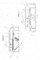
figure 2 shows in an enlarged scale a three-quarter front perspective view of one rotating lighting module of the invention pertaining to the lighting device offigure 1 ; -
figure 3 shows the same rotating lighting module offigure 2 , with parts removed in order to show the inner structure thereof; -
figure 4 shows a detail of one rotating unit of the rotating lighting module offigures 2 and3 ; -
figure 5 shows a sectioned side elevation view of the lighting module offigure 2 ; and -
figure 6 and 7 show in a further enlarged scale respective side elevation views,figure 7 in section, of a same detail of the lighting module offigure 2 . - With reference to
figure 1 ,reference number 1 indicates as a whole a lighting device consisting, in the non-limiting embodiment shown, in a vehicle headlight assembly, which is only schematically shown from the front, with parts, which are not essential for describing the invention, removed for sake of simplicity. - The
lighting device 1 comprises a generally cup-shaped housing body 2 designed to be mounted on a vehicle, known and not shown for sake of simplicity.Housing body 2 is made of synthetic plastic material by injection molding and has a front inlet opening 3 in use facing opposite to the vehicle and toward a forward driving direction FD of the vehicle, indicated by an arrow; the front inlet opening is closed by a transparent cover, normally constituted by a terse lens (i.e. a transparent lens not provided with optical functions), known and not shown (removed) for sake of simplicity . - According to the present invention, the
lighting device 1 comprises a stationarymain lighting module 4 and a plurality (e.g. at least two or more than two) ofsecondary lighting modules 5, each rotating around a respective axis, arranged generally vertical. Thelighting modules housing body 2, facing the inlet opening 3 and the rotatinglighting modules 5 are arranged within thehousing body 2, as it will be seen in greater details herein below, pivoting around respective first axes A1, A2 and A3, arranged all parallel to each other. - The
main lighting module 4 has an optical axis O arranged parallel to the forward march direction FD and along which the light beam generated in use by thelighting module 4 is delivered. Likewise, eachrotating lighting module 5 has its own optical axis O1, which may be rotated in use around the respective pivoting axes A1, A2 and A3. - A rotating
lighting module 5 for vehicles according to the invention is shown in an enlarged scale and in details infigures 2 ,3 and5-7 . - For sake of simplicity it is shown and it will be described the
lighting module 5 closer to themain lighting module 4, i.e. that one rotating around a pivoting axis A1; it is clear, however, that, according to one feature of the invention, theother lighting modules 5 in thesame lighting device 1 are identical to that one closer to themain lighting module 4, i.e. all therotating lighting modules 5 are identical to one another. - Each rotating
lighting module 5 comprises at least onelight source 6, at least onereflector 7 and at least oneactuator 8 to rotate thereflector 7 relative to thelight source 6 around a first pivoting axis A, in the example shown the axis A1. - According one feature of the invention, each
lighting module 5 further comprises alens 9, which is assembled angularly rigid with thereflector 7 and forms, together with thereflector 7, a rotatingoptical unit 10 powered by theactuator 8. - The at least one
light source 6, theactuator 8 and the rotatingoptical unit 10 are operatively associated with aframed support 11 holding rigid in a fixed position thelight source 6 and bearing in idling manner the rotatingoptical unit 10. - The
light source 6 is borne by a printedcircuit board 12, also bearingelectronic components 13, known in the art, to control thelight source 6. - If necessary or preferred, the printed
circuit board 12 bears more than one light source, e.g. further two or three, to perform different lighting functions. Thelight source 6 is preferably a LED. - According to a first main feature of the invention, the
framed support 11 is formed by a rigid metallic structure, generally C-shaped, e.g. realized in a press-molded, aluminum based, light alloy. - According to a further main feature of the invention, in combination with the above first main feature, each
lighting module 5 is configured so that the corresponding rotatingoptical unit 10 is supported in idly manner solely by abottom portion 14 of theframed support 11 of eachmodule 5. Moreover, the rotatingoptical unit 10 is self-supporting and is configured (figures 3,4 ) to form within the corresponding lighting module 5 afirst sub-assembly 15, which is completely independent of anupper portion 16 of theframed support 11 bearing the at least onelight source 6, in the case in point bearing the whole printedcircuit board 12 with the at least one (or more)light source 6 and theelectronic components 13. - In particular, the at least one
light source 6 with the printedcircuit board 12 and theelectronic components 13 form within the corresponding lighting module 5 asecond sub-assembly 18 supported solely by theupper portion 16 of theframed support 11. - In this manner, according to a feature of the invention and contrary to the prior art, the
first sub-assembly 15 is mechanically disconnected in rotation from thesecond sub-assembly 18. - At this purpose, the first sub-assembly 15 (
figures 3,4 ) comprises a rigid box-like structure 19 connecting thereflector 7 with thelens 9, facing to each other, and ashaft 20 having a symmetry axis coinciding with the first axis A (axis A1 in the embodiment shown) ; theshaft 20 is configured such as to project in cantilever fashion from the rigid box-like structure 19, in particular from the bottom thereof, namely on the side thereof facing away from theprinted circuit board 12 and therespective sub-assembly 18. - According to the invention, the
shaft 20 is housed entirely within a first through seat 21 (figures 3 and5 ) provided in thebottom portion 14 of theframed support 11 and is supported by a first rollingbearing 22 and by a second rollingbearing 23 housed withinopposite ends seat 21. - The
rolling bearings shaft 20 at respectiveopposite ends shaft 20 with thebearings shaft 20 is the sole, unique, single support and rotational guide for the rotatingoptical unit 10. - According to the invention, the
shaft 20 is of a tubular shape (seefigure 5 ), being axially crossed by a second throughseat 28 so as to be delimited laterally by anannular wall 29. - Moreover, the
shaft 20 is configured such as to be elastically deformable in radial direction at least at theopposite ends - This is obtained in the non-limitative embodiment shown by providing both
ends radial slots 30 extending axially; theradial slots 30 are open-ended at respective terminal edges of theends - According to a feature of the invention, the
first sub-assembly 15 further comprises (figure 5 ) arod 31 designed to be removably inserted axially within the second throughseat 28 in order to prevent, when inserted, any radial deformation of theshaft 20 and so rendering it completely rigid. - In the non-limitative embodiment shown the
rod 31 is threaded and is screwed into theseat 28. Another way of coupling, e.g. a snap-coupling, may be used in alternative, even if the screw coupling is safer and is preferred. - According to a feature of the invention, the
shaft 20 has to have in axial direction a length comparable with the height of the box-likerigid structure 19 in the same axial direction. Here and below for "comparable" is intended that the length ofshaft 20 is at least of the same order of magnitude of the height of the box-structure 19 and preferably that the two differ for less than the 20%. - According to the invention, the
shaft 20 has itsside wall 29 provided radially outwards with at least one axial groove 32 (preferably at least threeaxial grooves 32 angularly spaced at 120° to each other). - The at least one
axial grove 32 is engaged by a first transmission wheel 33 (figure 5 - a toothed wheel orgear 33, in the embodiment shown) fitted axially uponshaft 20; in fact, in the preferred embodiment shown, thebottom portion 14 of theframed support 11 is shaped as a box forming externally on theframed support 11 an internally hollow plate-like base 34 (figure 2 ). - The rotating
optical unit 10 projects axially upwards in cantilever fashion from thebottom portion 14 of theframed support 11, namely from the internally hollow plate-like base 34, towards theupper portion 16 of theframed support 11, remaining spaced apart from theupper portion 16 - The
actuator 8 is carried externally by thebottom portion 14 of theframed support 11, in particular by the internally hollow plate-like base 34, on the side opposite to the rotatingoptical unit 10; theactuator 8 is moreover mechanically connected to thetransmission wheel 33 by transmission elements, e.g. other two toothed gears 35 (figure 5 ); thetransmission wheel 33 and thetransmission elements 35 are housed idly within the plate-like base 34 formed by thebottom portion 14 of theframed support 11. - Of course, other means of transmission could be used, e.g. a transmission belt connecting directly the output shaft of the
actuator 8 with thetransmission wheel 33 keyed onto theshaft 20 in order to make theshaft 20 to rotate around axis A1. - As mentioned above, the
framed support 11 is generally C-shaped and, according to a further feature of the invention, is formed (figure 2 ) by two specular-symmetrical half-shells 36, one of which is better shown alone infigure 3 ) mechanically coupled together side by side at a plane parallel to the half-shells 36, i.e. parallel to their laying plane, and containing the first axis A, in the example shown axis A1. The two half-shells 36 are coupled together in a removable manner, so as to be separable, in the embodiment shown by means oflateral screws 37. - Each half-shell comprises (
figure 3 ): a L-shaped portion 38 configured as a solid, profiled element having a double T shape in cross-section and defining with its opposite wings, when the two half-shells 36 are coupled, theupper portion 16 and amiddle portion 39 of theframed support 11; and a bottom cup-shaped section 40 configured such as, when the two half-shells 36 are coupled, extends parallel to and facing with theupper portion 16 of theframed support 11, to which is connected by themiddle portion 39. - The bottom cup-
shaped sections 40 of the two half-shells 36 form, when the latter are coupled together, the plate-likehollow base 34 defining/delimiting at least part of thebottom portion 14 of theframed support 11. - In this manner, the assembly of each rotating
lighting module 5 is extremely easy. Moreover, the rotatingoptical unit 10 is guided with precision and without the risk of oscillations/vibrations by the combination of the partially hollow, rigid and metallicframed support 11 with the projectingshaft 20 borne rigid with the rotatingoptical unit 10 and with the supporting rolling bearing 22,23 thereof arranged at theopposite ends shaft 20. - Moreover, since the rotating
optical unit 10 is mechanically completely separated from the printedcircuit board 12 as far as its rotation capability is concerned, both wear of the rotation seat through the printed circuit board (which exists no more according to the invention) and the formation of dust due to wear are avoided, so impeding both the possible generation of noise and the possible impairment of the optical performances of the lighting module in use. - All the aims of the invention are therefore accomplished.
Claims (7)
- A rotating lighting module (5) for vehicles, comprising at least one light source (6), at least one reflector (7) and at least one actuator (8) to rotate the reflector relative to the light source around a first axis (A); wherein the reflector (7) forms, together with a lens (9) assembled angularly rigid therewith, a rotating optical unit (10) powered by said actuator (8) and wherein the light source, the actuator and the rotating optical unit are operatively associated with a framed support (11) holding rigid in a fixed position the light source (6) and bearing in idling manner said rotating optical unit (10); the light source (6) being borne by a printed circuit board (12) also bearing electronic components (13) to control the light source; wherein, in combination:i)- the framed support (11) is formed by a rigid metallic structure;ii)- the rotating optical unit (10) is supported in idly manner solely by a bottom portion (14) of the framed support (11) and forms a first sub-assembly (15), said sub-assembly being completely independent in rotation of an upper portion (16) of the framed support (11) bearing the at least one light source (6);iii)- the at least one light source (6) with the printed circuit board (12) and the electronic components (13) forming a second sub-assembly (18) supported solely by the upper portion (16) of the framed support;iv)- such as the first sub-assembly (15) is mechanically disconnected in rotation from the second sub-assembly (18); and wherein the first sub-assembly (15) comprises a rigid box-like structure (19) connecting the reflector (7) with the lens (9) facing to each other, and a shaft (20) having a symmetry axis coinciding with the first axis and projecting in cantilever fashion from a bottom of the rigid box-like structure (19); the shaft (20) being housed entirely within a first through seat (21) provided in the bottom portion (14) of the framed support (11) and being supported by a first and a second rolling bearing (22,23) housed within opposite ends (24,25) of the first through seat (21), coupled idly with the shaft (20) at respective opposite ends (26,27) thereof; said shaft (20) being the sole support and rotational guide for the rotating optical unit (10);characterized in that said shaft (20) is of a tubular shape, being axially crossed by a second through seat (28), the second through seat (28) being delimited laterally along the first axis (A) by an annular wall (29) of the shaft (20); said shaft (20) being configured such as to be elastically deformable in radial direction at least at the said opposite ends (26,27) thereof.
- A lighting module according to claim 1, characterized in that the first sub-assembly (15) further comprises a rod (31) designed to be removably inserted axially within said second through seat (28) in order to prevent any radial deformation of the shaft (20).
- A lighting module according to anyone of the preceding claims, characterized in that said shaft (20) has in axial direction a length comparable with the height of said rigid box-like structure (19).
- A lighting module according to anyone of the preceding claims, characterized in that said annular wall (29) is provided radially outwards with at least one axial groove (32); said axial grove (32) being engaged by a first transmission wheel (33) fitted axially upon said shaft (20); said bottom portion (14) of the framed support (11) being shaped as a box forming an internally hollow plate-like base (34); said rotating optical unit (10) projecting axially upwards in cantilever fashion from the internally hollow plate-like base (34) of the bottom portion (14) of the framed support (11) and towards the upper portion (16) of the framed support, remaining spaced apart from the upper portion (16) of the framed support; and said actuator (8) being carried externally by the bottom portion (14) of the framed support on the side opposite to the rotating optical unit (10) and being mechanically connected to the transmission wheel (33) by transmission elements (35), the transmission wheel (33) and the transmission elements (35) being housed idly within the plate-like base (34) formed by said bottom portion (14) of the framed support.
- A lighting module according to anyone of the preceding claims, characterized in that the framed support (11) is generally C-shaped and is formed by two half-shells (36) mechanically coupled together side by side in a removable manner at a plane parallel to the half-shells and containing the first axis (A); each half-shell (36) comprising: a L-shaped portion (38) configured as a solid, profiled element having a double T cross-section and defining said upper portion (16) and a middle portion (39) of the framed support (11) when the two half-shells (36) are coupled; and a bottom cup-shaped section (40) extending parallel to and facing with the upper portion (16) and connected thereto by the middle portion (39) with the half-shells (36) coupled; the bottom cup-shaped sections (40) of the two half-shells (36) forming, when the latter are coupled together, a plate-like hollow base (34) defining at least part of said bottom portion (14) of the framed support (11).
- A lighting device (1) for a vehicle comprising a plurality of lighting modules (5) according to anyone of the preceding claims, arranged side by side within a cup-shaped housing body (2) .
- Vehicle provided with a lighting device (1) according to claim 6.
Priority Applications (2)
| Application Number | Priority Date | Filing Date | Title |
|---|---|---|---|
| EP17185381.5A EP3441665B1 (en) | 2017-08-08 | 2017-08-08 | Rotating lighting module for vehicles and associated lighting device for vehicles |
| CN201810896508.2A CN109386806B (en) | 2017-08-08 | 2018-08-08 | Rotary lighting module for a vehicle and associated lighting device for a vehicle |
Applications Claiming Priority (1)
| Application Number | Priority Date | Filing Date | Title |
|---|---|---|---|
| EP17185381.5A EP3441665B1 (en) | 2017-08-08 | 2017-08-08 | Rotating lighting module for vehicles and associated lighting device for vehicles |
Publications (2)
| Publication Number | Publication Date |
|---|---|
| EP3441665A1 EP3441665A1 (en) | 2019-02-13 |
| EP3441665B1 true EP3441665B1 (en) | 2022-05-11 |
Family
ID=59592862
Family Applications (1)
| Application Number | Title | Priority Date | Filing Date |
|---|---|---|---|
| EP17185381.5A Active EP3441665B1 (en) | 2017-08-08 | 2017-08-08 | Rotating lighting module for vehicles and associated lighting device for vehicles |
Country Status (2)
| Country | Link |
|---|---|
| EP (1) | EP3441665B1 (en) |
| CN (1) | CN109386806B (en) |
Family Cites Families (21)
| Publication number | Priority date | Publication date | Assignee | Title |
|---|---|---|---|---|
| JP3242833B2 (en) * | 1996-03-14 | 2001-12-25 | 株式会社小糸製作所 | Lamp reflector |
| JP3883356B2 (en) * | 2000-03-14 | 2007-02-21 | 株式会社小糸製作所 | Reflector movable automotive headlamp |
| JP4043926B2 (en) * | 2002-11-28 | 2008-02-06 | 株式会社小糸製作所 | Vehicle headlamp |
| JP4353241B2 (en) * | 2006-11-24 | 2009-10-28 | 市光工業株式会社 | Vehicular headlamp leveling device and vehicular headlamp equipped with a leveling device |
| CA2810700C (en) * | 2010-07-26 | 2017-01-17 | Valeo Vision | Optical module of an illuminating and/or signalling device of a motor vehicle |
| US20130051059A1 (en) * | 2011-08-30 | 2013-02-28 | General Electric Company | Optically adjustable light module |
| JP5898937B2 (en) * | 2011-12-05 | 2016-04-06 | 株式会社小糸製作所 | Vehicle headlamp |
| JP5912757B2 (en) * | 2012-03-28 | 2016-04-27 | 本田技研工業株式会社 | Support structure for straddle-type vehicles |
| EP2669571A1 (en) * | 2012-06-01 | 2013-12-04 | OSRAM GmbH | Lighting module and corresponding integrated lighting system |
| FR3004396B1 (en) * | 2013-04-10 | 2015-04-17 | Peugeot Citroen Automobiles Sa | PROJECTOR EQUIPPED WITH ESCAMOTABLE LIGHTING MODULES |
| DE102014118342A1 (en) * | 2013-12-17 | 2015-06-18 | Richard Bergner Verbindungstechnik Gmbh & Co. Kg | Method for captive application of a washer to the shank of a screw |
| FR3016566B1 (en) * | 2014-01-17 | 2016-01-29 | Peugeot Citroen Automobiles Sa | PENDULUM LIGHTING DEVICE FOR MOTOR VEHICLE |
| FR3017189B1 (en) | 2014-02-04 | 2019-04-26 | Valeo Vision | ROTARY LIGHTING AND / OR SIGNALING MODULE WITH FIXED LIGHT SOURCE |
| FR3020289B1 (en) * | 2014-04-25 | 2017-02-10 | Faurecia Sieges D'automobile | METHOD FOR ASSEMBLING AN ASSEMBLY COMPRISING A TUBE AND A PLATE AND ASSEMBLY THEREFOR |
| FR3022325B1 (en) * | 2014-06-16 | 2016-07-29 | Valeo Vision | ROTARY LIGHTING AND / OR SIGNALING MODULE |
| FR3022322B1 (en) | 2014-06-16 | 2016-07-15 | Valeo Vision | ROTARY LIGHTING AND / OR SIGNALING MODULE |
| EP3009300B1 (en) * | 2014-10-13 | 2021-01-06 | MARELLI AUTOMOTIVE LIGHTING ITALY S.p.A. | Automotive light |
| JP2017013734A (en) * | 2015-07-06 | 2017-01-19 | Ntn株式会社 | Vehicular lighting device |
| CN205118862U (en) * | 2015-10-15 | 2016-03-30 | 大茂伟瑞柯车灯有限公司 | Car car light angle adjustment mechanism |
| CN105387410A (en) * | 2015-11-24 | 2016-03-09 | 马瑞利汽车零部件(芜湖)有限公司 | AFS dimming module for automobile lamp |
| EP3176493B1 (en) * | 2015-11-24 | 2020-12-30 | Marelli Automotive Lighting Italy S.p.A. | Rotating lighting module and lighting device for vehicles |
-
2017
- 2017-08-08 EP EP17185381.5A patent/EP3441665B1/en active Active
-
2018
- 2018-08-08 CN CN201810896508.2A patent/CN109386806B/en active Active
Also Published As
| Publication number | Publication date |
|---|---|
| CN109386806A (en) | 2019-02-26 |
| CN109386806B (en) | 2022-04-05 |
| EP3441665A1 (en) | 2019-02-13 |
Similar Documents
| Publication | Publication Date | Title |
|---|---|---|
| US9509248B2 (en) | Steering device for use in solar tracking equipment | |
| US7621663B2 (en) | Lamp device for vehicles | |
| CN104913271B (en) | Adjusting apparatus for headlight for vehicles | |
| US9971231B2 (en) | Diaphragm device and optical instrument | |
| RU2007137998A (en) | TWO-CIRCUIT TURBOREACTIVE ENGINE AND INTERMEDIATE HOUSING WITH A SHAFT FOR DRIVING THE POWER TAKE-OFF REDUCER FOR THE DRIVE OF AUXILIARY UNITS OF THE TURBOJET ENGINE | |
| KR101423538B1 (en) | Planetary gear type gear speed reducer and increaser | |
| US10352399B2 (en) | Actuator assembly | |
| US10670134B2 (en) | Gear box, driving device, and electronic apparatus | |
| EP3441665B1 (en) | Rotating lighting module for vehicles and associated lighting device for vehicles | |
| US11131846B2 (en) | Single-axis rotary actuator | |
| CN105416159A (en) | Adjusting System For A Vehicle Headlamp | |
| KR20200024085A (en) | Setting device for a motor vehicle headlamp | |
| US10340782B2 (en) | Method of reducing sound from light fixture with stepper motors | |
| US7121706B2 (en) | Vehicle headlamp unit | |
| US20200047848A1 (en) | Power assembly of electric scooter | |
| KR101920042B1 (en) | Actuator apparatus with insert bush | |
| US7926993B2 (en) | Projector unit | |
| US10260728B2 (en) | Rotary light module | |
| US7611268B2 (en) | Headlight adjustment device with dual input gear mechanism | |
| KR20180053708A (en) | Electromechanical brake booster and manufacturing method of electromechanical brake booster | |
| CN110454746A (en) | Regulating device for automotive headlight | |
| KR101759171B1 (en) | Motor module with transmission | |
| JP2014201196A (en) | Electric power steering device | |
| KR20180080982A (en) | Cam device and method for manufacturing cam device | |
| JP4717746B2 (en) | Geared motor and manufacturing method thereof |
Legal Events
| Date | Code | Title | Description |
|---|---|---|---|
| PUAI | Public reference made under article 153(3) epc to a published international application that has entered the european phase |
Free format text: ORIGINAL CODE: 0009012 |
|
| STAA | Information on the status of an ep patent application or granted ep patent |
Free format text: STATUS: THE APPLICATION HAS BEEN PUBLISHED |
|
| AK | Designated contracting states |
Kind code of ref document: A1 Designated state(s): AL AT BE BG CH CY CZ DE DK EE ES FI FR GB GR HR HU IE IS IT LI LT LU LV MC MK MT NL NO PL PT RO RS SE SI SK SM TR |
|
| AX | Request for extension of the european patent |
Extension state: BA ME |
|
| STAA | Information on the status of an ep patent application or granted ep patent |
Free format text: STATUS: REQUEST FOR EXAMINATION WAS MADE |
|
| 17P | Request for examination filed |
Effective date: 20190805 |
|
| RBV | Designated contracting states (corrected) |
Designated state(s): AL AT BE BG CH CY CZ DE DK EE ES FI FR GB GR HR HU IE IS IT LI LT LU LV MC MK MT NL NO PL PT RO RS SE SI SK SM TR |
|
| RAP1 | Party data changed (applicant data changed or rights of an application transferred) |
Owner name: MARELLI AUTOMOTIVE LIGHTING ITALY S.P.A. Owner name: PSA AUTOMOBILES SA |
|
| RAP1 | Party data changed (applicant data changed or rights of an application transferred) |
Owner name: MARELLI AUTOMOTIVE LIGHTING ITALY S.P.A. Owner name: PSA AUTOMOBILES SA |
|
| STAA | Information on the status of an ep patent application or granted ep patent |
Free format text: STATUS: EXAMINATION IS IN PROGRESS |
|
| 17Q | First examination report despatched |
Effective date: 20210223 |
|
| STAA | Information on the status of an ep patent application or granted ep patent |
Free format text: STATUS: EXAMINATION IS IN PROGRESS |
|
| GRAP | Despatch of communication of intention to grant a patent |
Free format text: ORIGINAL CODE: EPIDOSNIGR1 |
|
| STAA | Information on the status of an ep patent application or granted ep patent |
Free format text: STATUS: GRANT OF PATENT IS INTENDED |
|
| INTG | Intention to grant announced |
Effective date: 20210623 |
|
| GRAJ | Information related to disapproval of communication of intention to grant by the applicant or resumption of examination proceedings by the epo deleted |
Free format text: ORIGINAL CODE: EPIDOSDIGR1 |
|
| STAA | Information on the status of an ep patent application or granted ep patent |
Free format text: STATUS: EXAMINATION IS IN PROGRESS |
|
| INTC | Intention to grant announced (deleted) | ||
| GRAP | Despatch of communication of intention to grant a patent |
Free format text: ORIGINAL CODE: EPIDOSNIGR1 |
|
| STAA | Information on the status of an ep patent application or granted ep patent |
Free format text: STATUS: GRANT OF PATENT IS INTENDED |
|
| INTG | Intention to grant announced |
Effective date: 20211214 |
|
| GRAS | Grant fee paid |
Free format text: ORIGINAL CODE: EPIDOSNIGR3 |
|
| GRAA | (expected) grant |
Free format text: ORIGINAL CODE: 0009210 |
|
| STAA | Information on the status of an ep patent application or granted ep patent |
Free format text: STATUS: THE PATENT HAS BEEN GRANTED |
|
| AK | Designated contracting states |
Kind code of ref document: B1 Designated state(s): AL AT BE BG CH CY CZ DE DK EE ES FI FR GB GR HR HU IE IS IT LI LT LU LV MC MK MT NL NO PL PT RO RS SE SI SK SM TR |
|
| REG | Reference to a national code |
Ref country code: GB Ref legal event code: FG4D |
|
| REG | Reference to a national code |
Ref country code: CH Ref legal event code: EP |
|
| REG | Reference to a national code |
Ref country code: AT Ref legal event code: REF Ref document number: 1491687 Country of ref document: AT Kind code of ref document: T Effective date: 20220515 |
|
| REG | Reference to a national code |
Ref country code: DE Ref legal event code: R096 Ref document number: 602017057251 Country of ref document: DE |
|
| REG | Reference to a national code |
Ref country code: IE Ref legal event code: FG4D |
|
| REG | Reference to a national code |
Ref country code: LT Ref legal event code: MG9D |
|
| REG | Reference to a national code |
Ref country code: NL Ref legal event code: MP Effective date: 20220511 |
|
| REG | Reference to a national code |
Ref country code: AT Ref legal event code: MK05 Ref document number: 1491687 Country of ref document: AT Kind code of ref document: T Effective date: 20220511 |
|
| PG25 | Lapsed in a contracting state [announced via postgrant information from national office to epo] |
Ref country code: SE Free format text: LAPSE BECAUSE OF FAILURE TO SUBMIT A TRANSLATION OF THE DESCRIPTION OR TO PAY THE FEE WITHIN THE PRESCRIBED TIME-LIMIT Effective date: 20220511 Ref country code: PT Free format text: LAPSE BECAUSE OF FAILURE TO SUBMIT A TRANSLATION OF THE DESCRIPTION OR TO PAY THE FEE WITHIN THE PRESCRIBED TIME-LIMIT Effective date: 20220912 Ref country code: NO Free format text: LAPSE BECAUSE OF FAILURE TO SUBMIT A TRANSLATION OF THE DESCRIPTION OR TO PAY THE FEE WITHIN THE PRESCRIBED TIME-LIMIT Effective date: 20220811 Ref country code: NL Free format text: LAPSE BECAUSE OF FAILURE TO SUBMIT A TRANSLATION OF THE DESCRIPTION OR TO PAY THE FEE WITHIN THE PRESCRIBED TIME-LIMIT Effective date: 20220511 Ref country code: LT Free format text: LAPSE BECAUSE OF FAILURE TO SUBMIT A TRANSLATION OF THE DESCRIPTION OR TO PAY THE FEE WITHIN THE PRESCRIBED TIME-LIMIT Effective date: 20220511 Ref country code: HR Free format text: LAPSE BECAUSE OF FAILURE TO SUBMIT A TRANSLATION OF THE DESCRIPTION OR TO PAY THE FEE WITHIN THE PRESCRIBED TIME-LIMIT Effective date: 20220511 Ref country code: GR Free format text: LAPSE BECAUSE OF FAILURE TO SUBMIT A TRANSLATION OF THE DESCRIPTION OR TO PAY THE FEE WITHIN THE PRESCRIBED TIME-LIMIT Effective date: 20220812 Ref country code: FI Free format text: LAPSE BECAUSE OF FAILURE TO SUBMIT A TRANSLATION OF THE DESCRIPTION OR TO PAY THE FEE WITHIN THE PRESCRIBED TIME-LIMIT Effective date: 20220511 Ref country code: ES Free format text: LAPSE BECAUSE OF FAILURE TO SUBMIT A TRANSLATION OF THE DESCRIPTION OR TO PAY THE FEE WITHIN THE PRESCRIBED TIME-LIMIT Effective date: 20220511 Ref country code: BG Free format text: LAPSE BECAUSE OF FAILURE TO SUBMIT A TRANSLATION OF THE DESCRIPTION OR TO PAY THE FEE WITHIN THE PRESCRIBED TIME-LIMIT Effective date: 20220811 Ref country code: AT Free format text: LAPSE BECAUSE OF FAILURE TO SUBMIT A TRANSLATION OF THE DESCRIPTION OR TO PAY THE FEE WITHIN THE PRESCRIBED TIME-LIMIT Effective date: 20220511 |
|
| PG25 | Lapsed in a contracting state [announced via postgrant information from national office to epo] |
Ref country code: RS Free format text: LAPSE BECAUSE OF FAILURE TO SUBMIT A TRANSLATION OF THE DESCRIPTION OR TO PAY THE FEE WITHIN THE PRESCRIBED TIME-LIMIT Effective date: 20220511 Ref country code: PL Free format text: LAPSE BECAUSE OF FAILURE TO SUBMIT A TRANSLATION OF THE DESCRIPTION OR TO PAY THE FEE WITHIN THE PRESCRIBED TIME-LIMIT Effective date: 20220511 Ref country code: LV Free format text: LAPSE BECAUSE OF FAILURE TO SUBMIT A TRANSLATION OF THE DESCRIPTION OR TO PAY THE FEE WITHIN THE PRESCRIBED TIME-LIMIT Effective date: 20220511 Ref country code: IS Free format text: LAPSE BECAUSE OF FAILURE TO SUBMIT A TRANSLATION OF THE DESCRIPTION OR TO PAY THE FEE WITHIN THE PRESCRIBED TIME-LIMIT Effective date: 20220911 |
|
| PG25 | Lapsed in a contracting state [announced via postgrant information from national office to epo] |
Ref country code: SM Free format text: LAPSE BECAUSE OF FAILURE TO SUBMIT A TRANSLATION OF THE DESCRIPTION OR TO PAY THE FEE WITHIN THE PRESCRIBED TIME-LIMIT Effective date: 20220511 Ref country code: SK Free format text: LAPSE BECAUSE OF FAILURE TO SUBMIT A TRANSLATION OF THE DESCRIPTION OR TO PAY THE FEE WITHIN THE PRESCRIBED TIME-LIMIT Effective date: 20220511 Ref country code: RO Free format text: LAPSE BECAUSE OF FAILURE TO SUBMIT A TRANSLATION OF THE DESCRIPTION OR TO PAY THE FEE WITHIN THE PRESCRIBED TIME-LIMIT Effective date: 20220511 Ref country code: EE Free format text: LAPSE BECAUSE OF FAILURE TO SUBMIT A TRANSLATION OF THE DESCRIPTION OR TO PAY THE FEE WITHIN THE PRESCRIBED TIME-LIMIT Effective date: 20220511 Ref country code: DK Free format text: LAPSE BECAUSE OF FAILURE TO SUBMIT A TRANSLATION OF THE DESCRIPTION OR TO PAY THE FEE WITHIN THE PRESCRIBED TIME-LIMIT Effective date: 20220511 Ref country code: CZ Free format text: LAPSE BECAUSE OF FAILURE TO SUBMIT A TRANSLATION OF THE DESCRIPTION OR TO PAY THE FEE WITHIN THE PRESCRIBED TIME-LIMIT Effective date: 20220511 |
|
| REG | Reference to a national code |
Ref country code: DE Ref legal event code: R097 Ref document number: 602017057251 Country of ref document: DE |
|
| PLBE | No opposition filed within time limit |
Free format text: ORIGINAL CODE: 0009261 |
|
| STAA | Information on the status of an ep patent application or granted ep patent |
Free format text: STATUS: NO OPPOSITION FILED WITHIN TIME LIMIT |
|
| PG25 | Lapsed in a contracting state [announced via postgrant information from national office to epo] |
Ref country code: MC Free format text: LAPSE BECAUSE OF FAILURE TO SUBMIT A TRANSLATION OF THE DESCRIPTION OR TO PAY THE FEE WITHIN THE PRESCRIBED TIME-LIMIT Effective date: 20220511 Ref country code: AL Free format text: LAPSE BECAUSE OF FAILURE TO SUBMIT A TRANSLATION OF THE DESCRIPTION OR TO PAY THE FEE WITHIN THE PRESCRIBED TIME-LIMIT Effective date: 20220511 |
|
| REG | Reference to a national code |
Ref country code: CH Ref legal event code: PL |
|
| 26N | No opposition filed |
Effective date: 20230214 |
|
| PG25 | Lapsed in a contracting state [announced via postgrant information from national office to epo] |
Ref country code: LU Free format text: LAPSE BECAUSE OF NON-PAYMENT OF DUE FEES Effective date: 20220808 Ref country code: LI Free format text: LAPSE BECAUSE OF NON-PAYMENT OF DUE FEES Effective date: 20220831 Ref country code: CH Free format text: LAPSE BECAUSE OF NON-PAYMENT OF DUE FEES Effective date: 20220831 |
|
| REG | Reference to a national code |
Ref country code: BE Ref legal event code: MM Effective date: 20220831 |
|
| PG25 | Lapsed in a contracting state [announced via postgrant information from national office to epo] |
Ref country code: SI Free format text: LAPSE BECAUSE OF FAILURE TO SUBMIT A TRANSLATION OF THE DESCRIPTION OR TO PAY THE FEE WITHIN THE PRESCRIBED TIME-LIMIT Effective date: 20220511 |
|
| PG25 | Lapsed in a contracting state [announced via postgrant information from national office to epo] |
Ref country code: IE Free format text: LAPSE BECAUSE OF NON-PAYMENT OF DUE FEES Effective date: 20220808 |
|
| PG25 | Lapsed in a contracting state [announced via postgrant information from national office to epo] |
Ref country code: BE Free format text: LAPSE BECAUSE OF NON-PAYMENT OF DUE FEES Effective date: 20220831 |
|
| PGFP | Annual fee paid to national office [announced via postgrant information from national office to epo] |
Ref country code: TR Payment date: 20230731 Year of fee payment: 7 Ref country code: IT Payment date: 20230720 Year of fee payment: 7 Ref country code: GB Payment date: 20230720 Year of fee payment: 7 |
|
| PGFP | Annual fee paid to national office [announced via postgrant information from national office to epo] |
Ref country code: FR Payment date: 20230720 Year of fee payment: 7 Ref country code: DE Payment date: 20230720 Year of fee payment: 7 |
|
| PG25 | Lapsed in a contracting state [announced via postgrant information from national office to epo] |
Ref country code: HU Free format text: LAPSE BECAUSE OF FAILURE TO SUBMIT A TRANSLATION OF THE DESCRIPTION OR TO PAY THE FEE WITHIN THE PRESCRIBED TIME-LIMIT; INVALID AB INITIO Effective date: 20170808 |