EP3441206A1 - Appareil de granulation de résine et procédé de détermination d'anomalie pour appareil de granulation de résine - Google Patents
Appareil de granulation de résine et procédé de détermination d'anomalie pour appareil de granulation de résine Download PDFInfo
- Publication number
- EP3441206A1 EP3441206A1 EP17810062.4A EP17810062A EP3441206A1 EP 3441206 A1 EP3441206 A1 EP 3441206A1 EP 17810062 A EP17810062 A EP 17810062A EP 3441206 A1 EP3441206 A1 EP 3441206A1
- Authority
- EP
- European Patent Office
- Prior art keywords
- sensors
- sensor
- die
- predetermined range
- limit value
- Prior art date
- Legal status (The legal status is an assumption and is not a legal conclusion. Google has not performed a legal analysis and makes no representation as to the accuracy of the status listed.)
- Granted
Links
Images


Classifications
-
- B—PERFORMING OPERATIONS; TRANSPORTING
- B26—HAND CUTTING TOOLS; CUTTING; SEVERING
- B26D—CUTTING; DETAILS COMMON TO MACHINES FOR PERFORATING, PUNCHING, CUTTING-OUT, STAMPING-OUT OR SEVERING
- B26D1/00—Cutting through work characterised by the nature or movement of the cutting member or particular materials not otherwise provided for; Apparatus or machines therefor; Cutting members therefor
- B26D1/01—Cutting through work characterised by the nature or movement of the cutting member or particular materials not otherwise provided for; Apparatus or machines therefor; Cutting members therefor involving a cutting member which does not travel with the work
- B26D1/12—Cutting through work characterised by the nature or movement of the cutting member or particular materials not otherwise provided for; Apparatus or machines therefor; Cutting members therefor involving a cutting member which does not travel with the work having a cutting member moving about an axis
- B26D1/25—Cutting through work characterised by the nature or movement of the cutting member or particular materials not otherwise provided for; Apparatus or machines therefor; Cutting members therefor involving a cutting member which does not travel with the work having a cutting member moving about an axis with a non-circular cutting member
- B26D1/26—Cutting through work characterised by the nature or movement of the cutting member or particular materials not otherwise provided for; Apparatus or machines therefor; Cutting members therefor involving a cutting member which does not travel with the work having a cutting member moving about an axis with a non-circular cutting member moving about an axis substantially perpendicular to the line of cut
- B26D1/28—Cutting through work characterised by the nature or movement of the cutting member or particular materials not otherwise provided for; Apparatus or machines therefor; Cutting members therefor involving a cutting member which does not travel with the work having a cutting member moving about an axis with a non-circular cutting member moving about an axis substantially perpendicular to the line of cut and rotating continuously in one direction during cutting
-
- B—PERFORMING OPERATIONS; TRANSPORTING
- B26—HAND CUTTING TOOLS; CUTTING; SEVERING
- B26D—CUTTING; DETAILS COMMON TO MACHINES FOR PERFORATING, PUNCHING, CUTTING-OUT, STAMPING-OUT OR SEVERING
- B26D5/00—Arrangements for operating and controlling machines or devices for cutting, cutting-out, stamping-out, punching, perforating, or severing by means other than cutting
- B26D5/20—Arrangements for operating and controlling machines or devices for cutting, cutting-out, stamping-out, punching, perforating, or severing by means other than cutting with interrelated action between the cutting member and work feed
- B26D5/26—Arrangements for operating and controlling machines or devices for cutting, cutting-out, stamping-out, punching, perforating, or severing by means other than cutting with interrelated action between the cutting member and work feed wherein control means on the work feed means renders the cutting member operative
-
- B—PERFORMING OPERATIONS; TRANSPORTING
- B29—WORKING OF PLASTICS; WORKING OF SUBSTANCES IN A PLASTIC STATE IN GENERAL
- B29B—PREPARATION OR PRETREATMENT OF THE MATERIAL TO BE SHAPED; MAKING GRANULES OR PREFORMS; RECOVERY OF PLASTICS OR OTHER CONSTITUENTS OF WASTE MATERIAL CONTAINING PLASTICS
- B29B9/00—Making granules
- B29B9/02—Making granules by dividing preformed material
- B29B9/06—Making granules by dividing preformed material in the form of filamentary material, e.g. combined with extrusion
- B29B9/065—Making granules by dividing preformed material in the form of filamentary material, e.g. combined with extrusion under-water, e.g. underwater pelletizers
-
- G—PHYSICS
- G01—MEASURING; TESTING
- G01M—TESTING STATIC OR DYNAMIC BALANCE OF MACHINES OR STRUCTURES; TESTING OF STRUCTURES OR APPARATUS, NOT OTHERWISE PROVIDED FOR
- G01M13/00—Testing of machine parts
- G01M13/02—Gearings; Transmission mechanisms
- G01M13/028—Acoustic or vibration analysis
-
- G—PHYSICS
- G01—MEASURING; TESTING
- G01M—TESTING STATIC OR DYNAMIC BALANCE OF MACHINES OR STRUCTURES; TESTING OF STRUCTURES OR APPARATUS, NOT OTHERWISE PROVIDED FOR
- G01M15/00—Testing of engines
- G01M15/04—Testing internal-combustion engines
- G01M15/12—Testing internal-combustion engines by monitoring vibrations
Definitions
- the present invention relates to a technique of shaping a resin into a pellet form.
- a resin pelletizer apparatus is an apparatus such that, with use of rotary blades that rotate at a high speed on a die surface having die holes formed therein, a molten resin having a strand shape (string shape) extruded from the die holes into water is cut, whereby the resin is shaped into a pellet form.
- the poor cutting refers to a phenomenon in which, for example, a pellet having a whisker-shaped portion is generated, or a plurality of pellets connected in a chain form are generated.
- Patent Literature 1 discloses a poor cutting detection method including a step of measuring the position of a cutter knife by allowing the cutter knife to abut against the die surface at each timing of standard position setting and setting the measured position as a standard position, a step of measuring the position of the cutter knife while rotating the cutter knife to cut the molten resin and setting the measured position as a current position, and a step of notifying a user of the occurrence of poor cutting with an alarm when a difference between the current position and the standard position becomes larger than a predetermined set value of clearance.
- Patent Literature 2 discloses a method of detecting a molten resin pressure in the inside of the die to change a bias value and controlling the pressing force of a cutter driving shaft. According to this method, an optimal cutting operation can be obtained in accordance with the change in the molten resin pressure.
- An object of the present invention is to provide a resin pelletizer apparatus and an abnormality determination method for a resin pelletizer apparatus that can determine that an abnormality giving rise to a cause of poor cutting has occurred.
- a resin pelletizer apparatus includes a die that has a die surface having a die hole formed therein; a rotary blade that cuts a resin extruded from the die hole into a pellet shape in water when being rotated on the die surface in the water; a sensor that detects elastic waves generated by the rotary blade during rotation on the die surface; and a determination unit that monitors an output value of the sensor and determines that an abnormality has occurred when the output value of the sensor is outside a predetermined range.
- FIG. 1 is a block diagram showing a configuration of a resin pelletizer apparatus 100 according to the present embodiment.
- the resin pelletizer apparatus 100 is provided with a resin pelletizer apparatus main body 110, a control unit 120, an operation panel 130, a notification unit 140, and two sensors 150.
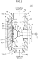
- FIG. 2 is a sectional view of the resin pelletizer apparatus main body 110.
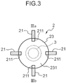
- FIG. 3 is a plan view when FIG. 2 is viewed in the direction of IIIa-IIIb.
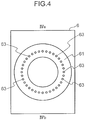
- FIG. 4 is a plan view when FIG. 2 is viewed in the direction of IVa-IVb.
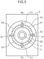
- FIG. 5 is a plan view when FIG. 2 is viewed in the direction of Va-Vb.
- the resin pelletizer apparatus main body 110 is provided with a chamber 1, a rotation head 2, a rotation shaft 3, a shaft bearing 4, a motor 5, and a die 6.
- the rotation head 2 is disposed in an inside 11 of the chamber 1.
- the rotation head 2 is fixed to one end of the rotation shaft 3.
- a through-hole is formed in a wall surface 13 of the chamber 1 that intersects with the rotation shaft 3, and the shaft bearing 4 is inserted and fitted into the through-hole.
- the shaft bearing 4 supports the rotation shaft 3.
- the other end of the rotation shaft 3 extends to an outside of the chamber 1 and is connected to the motor 5.
- the rotation head 2 includes four rotary blades 21 and a fixation unit 23 to which each rotary blade 21 is fixed.
- the fixation unit 23 has a circular cone frustum shape, and the rotation shaft 3 is fixed to one end surface of the fixation unit 23.
- the four rotary blades 21 are arranged at an interval of 90 degrees on the other end surface of the fixation unit 23 (bottom surface 231 of the circular cone frustum). Description will be given on an example in which the number of the rotary blades 21 is four; however, the number of the rotary blades 21 is not limited to four.
- Each rotary blade 21 has a generally rectangular shape, and the longitudinal direction of the rotary blade 21 is directed in the radial direction of the other end surface of the fixation unit 23 (bottom surface 231 of the circular cone frustum).
- One end 211 of the rotary blade 21 is fixed to an edge of the other end surface of the fixation unit 23 (bottom surface 231 of the circular cone frustum), and the rotary blade 21 rotates on the outside of the other end surface of the fixation unit 23 (bottom surface 231 of the circular cone frustum).
- a through-hole is formed in a wall surface 15 of the chamber 1 that opposes the other end surface of the fixation unit 23 (bottom surface 231 of the circular cone frustum). This through-hole is occupied by the die 6.
- the die 6 has a die surface 61 that is disposed in an inside 11 of the chamber 1.
- the die surface 61 has a circular disk shape and has a plurality of die holes 63 formed therein at an equal interval in a ring shape.
- the die holes 63 penetrate through the die 6.
- the die holes 63 are opened to a passageway where the rotary blades 21 rotate, and a molten resin extruded from an extruder (not illustrated in the drawings) passes through the die holes 63 to be extruded from the die holes 63 and is cut by the rotary blades 21 on the die surface 61. This allows the molten resin to be shaped into a pellet form.
- the inside 11 of the chamber 1 is filled with water, so that the rotation head 2, the die surface 61, and the die holes 63 are in water.
- the pellets are cooled by the water in the inside 11 of the chamber 1.
- a through-hole constituting a flow inlet 10 is formed in a wall surface 17 of the chamber 1.
- a through-hole constituting a flow outlet 12 is formed in a wall surface 19 of the chamber 1.
- Water is sent through the flow inlet 10 into the inside 11 of the chamber 1, and the inside 11 is filled with water.
- the water in the inside 11 is guided through the flow outlet 12 to the outside of the chamber 1 so as to be sent again through the flow inlet 10 into the inside 11 of the chamber 1.
- the control unit 120 controls the resin pelletizer apparatus main body 110.
- the control unit 120 is a computer realized by a CPU (Central Processing Unit), a RAM (Random Access Memory), a ROM (Read Only Memory), and others.
- the control unit 120 includes a determination unit 121 as a functional block. This functional block will be described later.
- the operation panel 130 is a device by which an input for operation of the resin pelletizer apparatus 100 is made. This input includes a command for start of the operation of the resin pelletizer apparatus 100, a command for stoppage of the operation, and the like.
- the notification unit 140 notifies a user of the occurrence of abnormality with an alarm when it is determined by the determination unit 121 that an abnormality has occurred during the operation of the resin pelletizer apparatus 100.
- the notification unit 140 is realized by a display, a speaker, an alarming lamp, or the like.
- the notification unit 140 is a display, an image showing that the abnormality has occurred is displayed.
- the notification unit 140 is a speaker, a sound telling that the abnormality has occurred is output.
- the notification unit 140 is an alarming lamp, the alarming lamp is lit.
- two sensors 150-1, 150-2 are disposed to be spaced apart from each other on a side surface of the die 6.
- the sensor 150-2 When viewed from the die surface 61, the sensor 150-2 is located at a position rotated by about 180 degrees from the position of the sensor 150-1.
- the resin pelletizer apparatus 100 While the resin pelletizer apparatus 100 is in operation, the rotary blades 21 rotate at a high speed on the die surface 61 in a state in which the rotary blades 21 are in contact with the die surface 61, so that elastic waves are generated.
- the sensor 150 detects the elastic waves.
- an AE Acoustic Emission
- a vibration sensor is used.
- An output value of the sensor 150 is an intensity of the signals that are output from the sensor 150 and indicates the magnitude of the supersonic waves generated by the rotary blades 21 during the rotation on the die surface 61.
- the output value of the sensor 150 is preferably a root mean square (RMS (root mean square) value) of the signals that are output from the sensor 150.
- the resin pelletizer apparatus 100 cuts the molten resin in water by rotating the rotary blades 21 at a high speed on the die surface 61 in a state in which the rotary blades 21 are in contact with the die surface 61. Poor cutting occurs in the following four cases.
- the contact surface pressure is a pressure by which the rotary blades 21 are pressed onto the die surface 61.
- the case (2) is, in other words, a state in which the rotation shaft 3 is not perpendicular to the die surface 61.
- the cavitation is a physical phenomenon in which generation and disappearance of bubbles occur in a short period of time due to the pressure difference in the flow of liquid.
- the experiment 1 will be described.
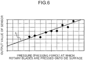
- the present inventors conducted an experiment of measuring the output value of the sensor 150 while changing the pressure by which the rotary blades 21 are pressed onto the die surface 61 (This pressure may also be referred to as "pressing force").
- FIG. 6 is a graph in which the experiment results are plotted.
- the lateral axis of the graph represents the pressing force, and the longitudinal axis represents the output value of the sensor 150.
- An experiment result of one of the two sensors 150 is plotted, and plotting of the experiment result of the other one is omitted.
- the straight line L is a regression line of the experiment result.
- the output value of the sensor 150 increases, whereas when the pressing force decreases, the output value of the sensor 150 decreases. From this, it will be understood that the output value of the sensor 150 is correlated to the pressing force (contact surface pressure between the rotary blades 21 and the die surface 61), and that the case in which the contact surface pressure is too large can be determined on the basis of the output value of the sensor 150.
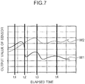
- FIG. 7 is a graph showing an output waveform W1 of the sensor 150-1 and an output waveform W2 of the sensor 150-2 in this experiment.
- the lateral axis of the graph represents the elapsed time
- the longitudinal axis represents the output value of the sensor 150.
- the elapsed time is a period of time that has elapsed from the start of measurement of the output value.
- the inclination of the die 6 is regarded as the inclination of the rotation shaft 3.
- the bolt located at a position close to the sensor 150-1 was loosened a little at the time point t1, further loosened a little at the time point t2, further loosened a little at the time point t3, and further loosened a little at the time point t4. This realizes a state in which the die 6 gradually becomes tilted.
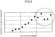
- FIG. 8 is a graph in which the experiment results are plotted.
- the lateral axis of the graph represents the rotation number of the rotation shaft 3, and the longitudinal axis represents the output value of the sensor 150.
- An experiment result of one of the two sensors 150 is plotted, and plotting of the experiment result of the other one is omitted.
- the output value of the sensor 150 increases; however, a cavitation occurred when the rotation number of the rotation shaft 3 exceeded a predetermined value n. It has been found out that the output value of the sensor 150 fluctuates up and down when the rotation number of the rotation shaft 3 exceeds the predetermined value n.
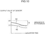
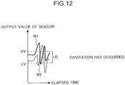
- FIGS. 9 to 12 are graphs for describing the discrimination of the four types of abnormality.
- the lateral axis represents the elapsed time
- the longitudinal axis represents the output value of the sensor 150.
- the output waveform W1 of the sensor 150-1 and the output waveform W2 of the sensor 150-2 are shown.
- a range R of the output value of the sensor 150 is defined in advance. Within the range R, none of the four types of abnormality occurs.
- An upper limit of the range R is defined as an upper limit value UV
- a lower limit of the range R is defined as a lower limit value LV.
- the range R assumes the same value; the upper limit value UV is the same value; and the lower limit value LV is the same value.
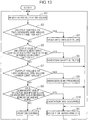
- FIG. 13 is a flowchart describing a process of discriminating and determining the four types of abnormality in the resin pelletizer apparatus 100 according to the present embodiment.
- the determination unit 121 monitors the output values of the two sensors 150 (step S1).
- the determination unit 121 determines whether or not it is established that the output values of the two sensors 150 are above the upper limit value UV at the same timing (step S2). When the determination unit 121 determines that this is established (Yes in step S2), the determination unit 121 determines that the contact surface pressure between the rotary blades 21 and the die surface 61 is too large (step S3). This allows the notification unit 140 to notify that the contact surface pressure is too large (step S4). After the step S4, the determination unit 121 performs the processes of the step S1 and monitors the output values of the two sensors 150.
- the determination unit 121 determines whether or not it is established that both of a case in which the output value of one of the sensors 150 is above the upper limit value UV and a case in which the output value of the other one of the sensors 150 is below the lower limit value LV have occurred at the same timing (step S5).
- the determination unit 121 determines that this is established (Yes in step S5), the determination unit 121 determines that the rotation shaft 3 is tilted (step S6). This allows the notification unit 140 to notify that the rotation shaft 3 is tilted (step S4).
- the determination unit 121 determines whether or not it is established that the output values of the two sensors 150 are below the lower limit value LV at the same timing (step S7).
- the determination unit 121 determines that this is established (Yes in step S7), the determination unit 121 determines that abrasion of at least one of the rotary blades 21 and the die surface 61 is in progress (step S8). This allows the notification unit 140 to notify that the abrasion of at least one of the rotary blades 21 and the die surface 61 is in progress (step S4).
- the determination unit 121 determines whether or not it is established that both of a case in which the output values of the two sensors 150 are above the upper limit value UV and a case in which the output values of the two sensors 150 are below the lower limit value LV have occurred within a predetermined period of time (step S9).
- the determination unit 121 determines that this is established (Yes in step S9), the determination unit 121 determines that a cavitation has occurred (step S10). This allows the notification unit 140 to notify that the cavitation has occurred (step S4).
- the determination unit 121 determines that it is not established that both of a case in which the output values of the two sensors 150 are above the upper limit value UV and a case in which the output values of the two sensors 150 are below the lower limit value LV have occurred within a predetermined period of time (No in step S9), the determination unit 121 determines that the resin pelletizer apparatus 100 is in normal operation and returns to the process of the step S1.
- the control unit 120 does not stop the operation of the resin pelletizer apparatus 100, but the notification unit 140 notifies the user of the abnormality (step S4), and the determination unit 121 continues monitoring the output values of the two sensors 150 (step S1).
- the present invention is not limited to this alone, so that, when the determination unit 121 determines an abnormality (steps S3, S6, S8, and S10), the control unit 120 may stop the operation of the resin pelletizer apparatus 100, and the notification unit 140 may notify the user of the abnormality (step S4).
- the countermeasures for eliminating the abnormality differ in accordance with the above-described four types of abnormality. Therefore, it is important to differentiate the four types of abnormality. As described above, according to the resin pelletizer apparatus 100 of the present embodiment, it is possible to discriminate and determine the four types of abnormality.
- the determination unit 121 does not determine the occurrence of cavitation but discriminates and determines the other three types of abnormality.
- the determination unit 121 does not determine the occurrence of cavitation or the progress of abrasion but discriminates and determines the other two types of abnormality.
- the determination unit 121 determines only the occurrence of cavitation.
- step S5 For determination of whether or not the rotation shaft 3 is tilted (step S5), two sensors 150 are needed ( FIG. 11 ); however, the other types of abnormality can be determined with use of one sensor 150. Accordingly, in a mode in which the determination of whether or not the rotation shaft 3 is tilted is not made, the determination unit 121 determines the abnormality with use of the output value of one sensor 150.
- a resin pelletizer apparatus includes a die that has a die surface having a die hole formed therein; a rotary blade that cuts a resin extruded from the die hole into a pellet shape in water when being rotated on the die surface in the water; a sensor that detects elastic waves generated by the rotary blade during rotation on the die surface; and a determination unit that monitors an output value of the sensor and determines that an abnormality has occurred when the output value of the sensor is outside a predetermined range.
- the resin pelletizer apparatus includes a sensor that detects elastic waves generated by the rotary blade during rotation on the die surface and a determination unit that determines that an abnormality has occurred when the output value of the sensor is outside a predetermined range, so that it can be determined that an abnormality giving rise to a cause of poor cutting has occurred.
- the determination unit can determine the following abnormality.
- the determination unit determines that a contact surface pressure between the rotary blade and the die surface is too large when the output value of the sensor is above an upper limit value of the predetermined range.
- the contact surface pressure is a pressure by which the rotary blade is pressed onto the die surface.
- the state that "the contact surface pressure is too large” means that the contact surface pressure is greater than or equal to a predetermined value as compared with a standard value of the contact surface pressure.
- the determination unit determines that an abrasion of at least one of the rotary blade and the die surface is in progress when the output value of the sensor is below a lower limit value of the predetermined range.
- the state that "an abrasion is in progress" means that the abrasion amount of the rotary blade or the abrasion amount of the die surface exceeds a predetermined value.
- the determination unit determines that a cavitation has occurred when both of a case in which the output value of the sensor is above an upper limit value of the predetermined range and a case in which the output value of the sensor is below a lower limit value of the predetermined range have occurred within a predetermined period of time.
- the resin pelletizer apparatus further includes a rotation shaft that drives the rotary blade and a plurality of the sensors that are disposed to be spaced apart from each other, wherein the determination unit determines that the rotation shaft is tilted when, among the plurality of the sensors, the output values of a part of the sensors are above an upper limit value of the predetermined range and the output values of a rest of the sensors are below a lower limit value of the predetermined range.
- the resin pelletizer apparatus further includes a rotation shaft that drives the rotary blade and a plurality of the sensors that are disposed to be spaced apart from each other, wherein the determination unit determines that a contact surface pressure between the rotary blade and the die surface is too large when the output values of the plurality of the sensors are each above an upper limit value of the predetermined range; the determination unit determines that an abrasion of at least one of the rotary blade and the die surface is in progress when the output values of the plurality of the sensors are each below a lower limit value of the predetermined range; the determination unit determines that a cavitation has occurred when both of a case in which the output values of the plurality of the sensors are each above an upper limit value of the predetermined range and a case in which the output values of the plurality of the sensors are each below a lower limit value of the predetermined range have occurred within a predetermined period of time; and the determination unit determines that the rotation shaft is tilted when, among the plurality of the sensors, the output values of
- the countermeasures for eliminating the abnormality differ in accordance with the above-described four types of abnormality. Therefore, it is important to differentiate the four types of abnormality. According to this configuration, it is possible to discriminate and determine the four types of abnormality.
- An abnormality determination method for a resin pelletizer apparatus is a method for determining that an abnormality has occurred in the resin pelletizer apparatus including a die that has a die surface having a die hole formed therein and a rotary blade that cuts a resin extruded from the die hole into a pellet shape in water when being rotated on the die surface in the water, the method including: a first step of detecting elastic waves generated by the rotary blade during rotation on the die surface; and a second step of monitoring a magnitude of the elastic waves detected in the first step and determining that an abnormality has occurred when the magnitude of the elastic waves is outside a predetermined range.
- the abnormality determination method for a resin pelletizer apparatus according to the second aspect of the present embodiment defines the resin pelletizer apparatus according to the first aspect of the present embodiment from the viewpoint of an abnormality determination method, and produces the same functions and effects as the resin pelletizer apparatus according to the first aspect of the present embodiment.
- the present invention can provide a resin pelletizer apparatus and an abnormality determination method for a resin pelletizer apparatus.
Landscapes
- Engineering & Computer Science (AREA)
- Mechanical Engineering (AREA)
- Life Sciences & Earth Sciences (AREA)
- Forests & Forestry (AREA)
- Physics & Mathematics (AREA)
- General Physics & Mathematics (AREA)
- Acoustics & Sound (AREA)
- Chemical & Material Sciences (AREA)
- Combustion & Propulsion (AREA)
- Processing And Handling Of Plastics And Other Materials For Molding In General (AREA)
- Extrusion Moulding Of Plastics Or The Like (AREA)
Applications Claiming Priority (2)
| Application Number | Priority Date | Filing Date | Title |
|---|---|---|---|
| JP2016116313A JP6639014B2 (ja) | 2016-06-10 | 2016-06-10 | 樹脂ペレタイザ装置 |
| PCT/JP2017/018367 WO2017212881A1 (fr) | 2016-06-10 | 2017-05-16 | Appareil de granulation de résine et procédé de détermination d'anomalie pour appareil de granulation de résine |
Publications (3)
| Publication Number | Publication Date |
|---|---|
| EP3441206A1 true EP3441206A1 (fr) | 2019-02-13 |
| EP3441206A4 EP3441206A4 (fr) | 2019-11-27 |
| EP3441206B1 EP3441206B1 (fr) | 2021-01-13 |
Family
ID=60578517
Family Applications (1)
| Application Number | Title | Priority Date | Filing Date |
|---|---|---|---|
| EP17810062.4A Active EP3441206B1 (fr) | 2016-06-10 | 2017-05-16 | Appareils de granulation de résine, et procédés de détermination d'anomalie associés |
Country Status (5)
| Country | Link |
|---|---|
| US (1) | US10661463B2 (fr) |
| EP (1) | EP3441206B1 (fr) |
| JP (1) | JP6639014B2 (fr) |
| CN (1) | CN109070371B (fr) |
| WO (1) | WO2017212881A1 (fr) |
Families Citing this family (5)
| Publication number | Priority date | Publication date | Assignee | Title |
|---|---|---|---|---|
| DE102019101808A1 (de) * | 2019-01-25 | 2020-07-30 | Voith Patent Gmbh | Steuerung der Faserstoffbehandlung |
| DE112020003178T5 (de) * | 2019-07-02 | 2022-04-07 | National University Corporation Kanazawa University | Abnormalitäts-Detektionsvorrichtung für Extrusionsgiessmaschine |
| DE102020003055A1 (de) * | 2020-05-22 | 2021-11-25 | Lenord, Bauer & Co. Gmbh | Verfahren zur Ermittlung der Belastung einer Antriebswelle |
| JP7534920B2 (ja) * | 2020-10-29 | 2024-08-15 | 株式会社日本製鋼所 | 樹脂切断装置、造粒機およびペレット製造方法 |
| CN113935994B (zh) * | 2021-12-15 | 2022-04-01 | 深圳市巨力方视觉技术有限公司 | 基于云数据共享的模切材料缺陷检校方法、装置及系统 |
Family Cites Families (25)
| Publication number | Priority date | Publication date | Assignee | Title |
|---|---|---|---|---|
| CN2113870U (zh) * | 1991-12-19 | 1992-08-26 | 辽阳石油化工专科学校斯佳机械配件厂 | 一种塑料挤压机造粒模板 |
| JP3003381B2 (ja) * | 1992-03-24 | 2000-01-24 | 東レ株式会社 | ペレットミル装置の異常検出装置 |
| US5330340A (en) * | 1992-03-25 | 1994-07-19 | The Black Clawson Company | Pelletizer with automatic knife adjustment |
| JPH06218726A (ja) * | 1993-01-26 | 1994-08-09 | Mitsubishi Rayon Co Ltd | 樹脂ペレット製造方法 |
| US5566092A (en) | 1993-12-30 | 1996-10-15 | Caterpillar Inc. | Machine fault diagnostics system and method |
| JPH09189644A (ja) | 1996-01-09 | 1997-07-22 | Hitachi Ltd | 摺動部異常診断装置及びその方法 |
| JP4120099B2 (ja) | 1999-07-09 | 2008-07-16 | 日本精工株式会社 | 軸受の異常診断方法および異常診断装置 |
| JP2001038676A (ja) | 1999-08-05 | 2001-02-13 | Japan Steel Works Ltd:The | プラスチック水中カッティング装置におけるカッティング不良検出方法およびプラスチック水中カッティング装置 |
| US6392584B1 (en) | 2000-01-04 | 2002-05-21 | Richard Eklund | System and method for detecting and warning of potential failure of rotating and vibrating machines |
| AT410072B (de) * | 2001-06-08 | 2003-01-27 | Erema | Verfahren und vorrichtung zur einstellung einer vorspannung der messer einer granuliervorrichtung |
| JP2003211442A (ja) | 2002-01-16 | 2003-07-29 | Kobe Steel Ltd | ペレタイザとこれに用いるナイフ及びダイプレート |
| EP1548419B1 (fr) | 2002-08-30 | 2013-07-24 | NSK Ltd. | Procede et dispositif de controle d'etat de materiel mecanique et dispositif de diagnostic d'anomalies |
| JP2004292702A (ja) * | 2003-03-27 | 2004-10-21 | Toray Ind Inc | 液晶性樹脂の製造方法 |
| US7226553B2 (en) * | 2003-07-30 | 2007-06-05 | E. I. Du Pont De Nemours And Company | Polymer underwater pelletizer apparatus and process incorporating same |
| US8186991B2 (en) * | 2004-02-27 | 2012-05-29 | Jmp Industries, Inc. | Extruder system and cutting assembly |
| DE102004020898B4 (de) * | 2004-04-28 | 2011-01-13 | Borsig Gmbh | Vorrichtung und Verfahren zum Messen und Anpassen des Anpressdruckes von Messern |
| JP5063005B2 (ja) * | 2006-02-01 | 2012-10-31 | 株式会社ジェイテクト | 音又は振動の異常診断方法及び音又は振動の異常診断装置 |
| DE102007016347A1 (de) * | 2007-04-03 | 2008-10-09 | Rieter Automatik Gmbh | Vorrichtung und Verfahren zur Herstellung von Kunststoffgranulat |
| US20080299243A1 (en) * | 2007-05-30 | 2008-12-04 | Pinchot James M | Extrusion cutting apparatus |
| JP2009006576A (ja) | 2007-06-28 | 2009-01-15 | Japan Steel Works Ltd:The | 樹脂水中カッティング装置におけるカッター刃押し付け圧の補正方法 |
| JP5190393B2 (ja) | 2009-02-04 | 2013-04-24 | 株式会社神戸製鋼所 | 樹脂造粒装置 |
| JP5186418B2 (ja) | 2009-03-05 | 2013-04-17 | 株式会社神戸製鋼所 | 樹脂造粒装置 |
| DE102010015776A1 (de) * | 2010-04-21 | 2011-10-27 | Automatik Plastics Machinery Gmbh | Vorrichtung und Verfahren zur Herstellung von Granulatkörnern |
| CN203427213U (zh) * | 2013-06-19 | 2014-02-12 | 汕头市富达塑料机械有限公司 | 水环式切粒装置 |
| JP6639013B2 (ja) * | 2016-03-14 | 2020-02-05 | 株式会社神戸製鋼所 | 樹脂ペレタイザ装置、及び、キャビテーション監視方法 |
-
2016
- 2016-06-10 JP JP2016116313A patent/JP6639014B2/ja active Active
-
2017
- 2017-05-16 EP EP17810062.4A patent/EP3441206B1/fr active Active
- 2017-05-16 CN CN201780030075.6A patent/CN109070371B/zh active Active
- 2017-05-16 US US16/098,957 patent/US10661463B2/en active Active
- 2017-05-16 WO PCT/JP2017/018367 patent/WO2017212881A1/fr not_active Ceased
Also Published As
| Publication number | Publication date |
|---|---|
| US10661463B2 (en) | 2020-05-26 |
| CN109070371B (zh) | 2020-08-11 |
| CN109070371A (zh) | 2018-12-21 |
| JP2017217745A (ja) | 2017-12-14 |
| EP3441206A4 (fr) | 2019-11-27 |
| EP3441206B1 (fr) | 2021-01-13 |
| JP6639014B2 (ja) | 2020-02-05 |
| US20190184590A1 (en) | 2019-06-20 |
| WO2017212881A1 (fr) | 2017-12-14 |
Similar Documents
| Publication | Publication Date | Title |
|---|---|---|
| US10661463B2 (en) | Resin pelletizer apparatus and abnormality determination method for resin pelletizer apparatus | |
| US10160153B2 (en) | Resin pelletizer device and cavitation monitoring method | |
| CN104093628B (zh) | 用于运行船只螺旋桨的装置及方法 | |
| US20190346354A1 (en) | Apparatus and method for measuring particle size distribution, and program for particle size distribution measuring apparatus | |
| EP1927829A2 (fr) | Dispositif de surveillance de procédé de travail | |
| CN109312760A (zh) | 泵的监测 | |
| US10639649B2 (en) | Feedback control method for the operation of a centrifuge | |
| KR20220010031A (ko) | 압출 성형기의 이상 검출 장치 | |
| US10342245B2 (en) | Method and apparatus for citrus juice processing | |
| JP6957819B2 (ja) | 汚泥脱水装置、汚泥脱水装置の制御方法およびプログラム | |
| JP2006281402A (ja) | 研削作業の状態を判定する方法及び同装置、並びに研削作業の制御方法 | |
| US20190336917A1 (en) | System for aerating a submerged membrane | |
| JP2020146673A (ja) | 流体取り込みシステム及び発電システム | |
| US9079192B2 (en) | Control method of a flotation machine that is used in metallurgical processes | |
| JP2023008161A (ja) | 自動運転安定化装置、自動運転安定化方法およびプログラム | |
| US20040250893A1 (en) | Apparatus for chipping material | |
| JP5088784B2 (ja) | 圧力センサを利用した網下気室型湿式比重選別機用回収制御装置 | |
| CN222093657U (zh) | 一种离心机上清液细胞状态监控装置 | |
| JP2004016886A (ja) | スクリーンの異常検出装置 | |
| KR20210077740A (ko) | 예지 보전 판정 장치, 예지 보전 판정 방법 및 기억 매체 |
Legal Events
| Date | Code | Title | Description |
|---|---|---|---|
| STAA | Information on the status of an ep patent application or granted ep patent |
Free format text: STATUS: THE INTERNATIONAL PUBLICATION HAS BEEN MADE |
|
| PUAI | Public reference made under article 153(3) epc to a published international application that has entered the european phase |
Free format text: ORIGINAL CODE: 0009012 |
|
| STAA | Information on the status of an ep patent application or granted ep patent |
Free format text: STATUS: REQUEST FOR EXAMINATION WAS MADE |
|
| 17P | Request for examination filed |
Effective date: 20181106 |
|
| AK | Designated contracting states |
Kind code of ref document: A1 Designated state(s): AL AT BE BG CH CY CZ DE DK EE ES FI FR GB GR HR HU IE IS IT LI LT LU LV MC MK MT NL NO PL PT RO RS SE SI SK SM TR |
|
| AX | Request for extension of the european patent |
Extension state: BA ME |
|
| DAV | Request for validation of the european patent (deleted) | ||
| DAX | Request for extension of the european patent (deleted) | ||
| A4 | Supplementary search report drawn up and despatched |
Effective date: 20191025 |
|
| RIC1 | Information provided on ipc code assigned before grant |
Ipc: B26D 5/00 20060101ALI20191021BHEP Ipc: B26D 1/28 20060101ALI20191021BHEP Ipc: B29B 9/06 20060101ALI20191021BHEP Ipc: G01H 1/00 20060101ALI20191021BHEP Ipc: G01M 13/028 20190101ALI20191021BHEP Ipc: B26D 5/26 20060101AFI20191021BHEP Ipc: G01M 15/12 20060101ALI20191021BHEP |
|
| STAA | Information on the status of an ep patent application or granted ep patent |
Free format text: STATUS: EXAMINATION IS IN PROGRESS |
|
| 17Q | First examination report despatched |
Effective date: 20200804 |
|
| REG | Reference to a national code |
Ref country code: DE Ref legal event code: R079 Ref document number: 602017031471 Country of ref document: DE Free format text: PREVIOUS MAIN CLASS: B26D0001280000 Ipc: B26D0005260000 |
|
| GRAP | Despatch of communication of intention to grant a patent |
Free format text: ORIGINAL CODE: EPIDOSNIGR1 |
|
| STAA | Information on the status of an ep patent application or granted ep patent |
Free format text: STATUS: GRANT OF PATENT IS INTENDED |
|
| RIC1 | Information provided on ipc code assigned before grant |
Ipc: G01M 15/12 20060101ALI20200925BHEP Ipc: G01M 13/028 20190101ALI20200925BHEP Ipc: B26D 1/28 20060101ALI20200925BHEP Ipc: B26D 5/26 20060101AFI20200925BHEP Ipc: B26D 5/00 20060101ALI20200925BHEP Ipc: B29B 9/06 20060101ALI20200925BHEP |
|
| INTG | Intention to grant announced |
Effective date: 20201014 |
|
| GRAS | Grant fee paid |
Free format text: ORIGINAL CODE: EPIDOSNIGR3 |
|
| GRAA | (expected) grant |
Free format text: ORIGINAL CODE: 0009210 |
|
| STAA | Information on the status of an ep patent application or granted ep patent |
Free format text: STATUS: THE PATENT HAS BEEN GRANTED |
|
| AK | Designated contracting states |
Kind code of ref document: B1 Designated state(s): AL AT BE BG CH CY CZ DE DK EE ES FI FR GB GR HR HU IE IS IT LI LT LU LV MC MK MT NL NO PL PT RO RS SE SI SK SM TR |
|
| REG | Reference to a national code |
Ref country code: GB Ref legal event code: FG4D |
|
| REG | Reference to a national code |
Ref country code: CH Ref legal event code: EP |
|
| REG | Reference to a national code |
Ref country code: IE Ref legal event code: FG4D |
|
| REG | Reference to a national code |
Ref country code: DE Ref legal event code: R096 Ref document number: 602017031471 Country of ref document: DE |
|
| REG | Reference to a national code |
Ref country code: AT Ref legal event code: REF Ref document number: 1354213 Country of ref document: AT Kind code of ref document: T Effective date: 20210215 |
|
| REG | Reference to a national code |
Ref country code: AT Ref legal event code: MK05 Ref document number: 1354213 Country of ref document: AT Kind code of ref document: T Effective date: 20210113 |
|
| REG | Reference to a national code |
Ref country code: NL Ref legal event code: MP Effective date: 20210113 |
|
| REG | Reference to a national code |
Ref country code: LT Ref legal event code: MG9D |
|
| PG25 | Lapsed in a contracting state [announced via postgrant information from national office to epo] |
Ref country code: GR Free format text: LAPSE BECAUSE OF FAILURE TO SUBMIT A TRANSLATION OF THE DESCRIPTION OR TO PAY THE FEE WITHIN THE PRESCRIBED TIME-LIMIT Effective date: 20210414 Ref country code: HR Free format text: LAPSE BECAUSE OF FAILURE TO SUBMIT A TRANSLATION OF THE DESCRIPTION OR TO PAY THE FEE WITHIN THE PRESCRIBED TIME-LIMIT Effective date: 20210113 Ref country code: FI Free format text: LAPSE BECAUSE OF FAILURE TO SUBMIT A TRANSLATION OF THE DESCRIPTION OR TO PAY THE FEE WITHIN THE PRESCRIBED TIME-LIMIT Effective date: 20210113 Ref country code: PT Free format text: LAPSE BECAUSE OF FAILURE TO SUBMIT A TRANSLATION OF THE DESCRIPTION OR TO PAY THE FEE WITHIN THE PRESCRIBED TIME-LIMIT Effective date: 20210513 Ref country code: NO Free format text: LAPSE BECAUSE OF FAILURE TO SUBMIT A TRANSLATION OF THE DESCRIPTION OR TO PAY THE FEE WITHIN THE PRESCRIBED TIME-LIMIT Effective date: 20210413 Ref country code: LT Free format text: LAPSE BECAUSE OF FAILURE TO SUBMIT A TRANSLATION OF THE DESCRIPTION OR TO PAY THE FEE WITHIN THE PRESCRIBED TIME-LIMIT Effective date: 20210113 Ref country code: BG Free format text: LAPSE BECAUSE OF FAILURE TO SUBMIT A TRANSLATION OF THE DESCRIPTION OR TO PAY THE FEE WITHIN THE PRESCRIBED TIME-LIMIT Effective date: 20210413 |
|
| PG25 | Lapsed in a contracting state [announced via postgrant information from national office to epo] |
Ref country code: RS Free format text: LAPSE BECAUSE OF FAILURE TO SUBMIT A TRANSLATION OF THE DESCRIPTION OR TO PAY THE FEE WITHIN THE PRESCRIBED TIME-LIMIT Effective date: 20210113 Ref country code: PL Free format text: LAPSE BECAUSE OF FAILURE TO SUBMIT A TRANSLATION OF THE DESCRIPTION OR TO PAY THE FEE WITHIN THE PRESCRIBED TIME-LIMIT Effective date: 20210113 Ref country code: LV Free format text: LAPSE BECAUSE OF FAILURE TO SUBMIT A TRANSLATION OF THE DESCRIPTION OR TO PAY THE FEE WITHIN THE PRESCRIBED TIME-LIMIT Effective date: 20210113 Ref country code: AT Free format text: LAPSE BECAUSE OF FAILURE TO SUBMIT A TRANSLATION OF THE DESCRIPTION OR TO PAY THE FEE WITHIN THE PRESCRIBED TIME-LIMIT Effective date: 20210113 Ref country code: SE Free format text: LAPSE BECAUSE OF FAILURE TO SUBMIT A TRANSLATION OF THE DESCRIPTION OR TO PAY THE FEE WITHIN THE PRESCRIBED TIME-LIMIT Effective date: 20210113 |
|
| PG25 | Lapsed in a contracting state [announced via postgrant information from national office to epo] |
Ref country code: IS Free format text: LAPSE BECAUSE OF FAILURE TO SUBMIT A TRANSLATION OF THE DESCRIPTION OR TO PAY THE FEE WITHIN THE PRESCRIBED TIME-LIMIT Effective date: 20210513 |
|
| REG | Reference to a national code |
Ref country code: DE Ref legal event code: R097 Ref document number: 602017031471 Country of ref document: DE |
|
| PG25 | Lapsed in a contracting state [announced via postgrant information from national office to epo] |
Ref country code: CZ Free format text: LAPSE BECAUSE OF FAILURE TO SUBMIT A TRANSLATION OF THE DESCRIPTION OR TO PAY THE FEE WITHIN THE PRESCRIBED TIME-LIMIT Effective date: 20210113 Ref country code: EE Free format text: LAPSE BECAUSE OF FAILURE TO SUBMIT A TRANSLATION OF THE DESCRIPTION OR TO PAY THE FEE WITHIN THE PRESCRIBED TIME-LIMIT Effective date: 20210113 Ref country code: SM Free format text: LAPSE BECAUSE OF FAILURE TO SUBMIT A TRANSLATION OF THE DESCRIPTION OR TO PAY THE FEE WITHIN THE PRESCRIBED TIME-LIMIT Effective date: 20210113 |
|
| PLBE | No opposition filed within time limit |
Free format text: ORIGINAL CODE: 0009261 |
|
| STAA | Information on the status of an ep patent application or granted ep patent |
Free format text: STATUS: NO OPPOSITION FILED WITHIN TIME LIMIT |
|
| PG25 | Lapsed in a contracting state [announced via postgrant information from national office to epo] |
Ref country code: DK Free format text: LAPSE BECAUSE OF FAILURE TO SUBMIT A TRANSLATION OF THE DESCRIPTION OR TO PAY THE FEE WITHIN THE PRESCRIBED TIME-LIMIT Effective date: 20210113 Ref country code: SK Free format text: LAPSE BECAUSE OF FAILURE TO SUBMIT A TRANSLATION OF THE DESCRIPTION OR TO PAY THE FEE WITHIN THE PRESCRIBED TIME-LIMIT Effective date: 20210113 Ref country code: RO Free format text: LAPSE BECAUSE OF FAILURE TO SUBMIT A TRANSLATION OF THE DESCRIPTION OR TO PAY THE FEE WITHIN THE PRESCRIBED TIME-LIMIT Effective date: 20210113 |
|
| 26N | No opposition filed |
Effective date: 20211014 |
|
| REG | Reference to a national code |
Ref country code: CH Ref legal event code: PL |
|
| GBPC | Gb: european patent ceased through non-payment of renewal fee |
Effective date: 20210516 |
|
| PG25 | Lapsed in a contracting state [announced via postgrant information from national office to epo] |
Ref country code: MC Free format text: LAPSE BECAUSE OF FAILURE TO SUBMIT A TRANSLATION OF THE DESCRIPTION OR TO PAY THE FEE WITHIN THE PRESCRIBED TIME-LIMIT Effective date: 20210113 Ref country code: LI Free format text: LAPSE BECAUSE OF NON-PAYMENT OF DUE FEES Effective date: 20210531 Ref country code: LU Free format text: LAPSE BECAUSE OF NON-PAYMENT OF DUE FEES Effective date: 20210516 Ref country code: CH Free format text: LAPSE BECAUSE OF NON-PAYMENT OF DUE FEES Effective date: 20210531 Ref country code: AL Free format text: LAPSE BECAUSE OF FAILURE TO SUBMIT A TRANSLATION OF THE DESCRIPTION OR TO PAY THE FEE WITHIN THE PRESCRIBED TIME-LIMIT Effective date: 20210113 Ref country code: ES Free format text: LAPSE BECAUSE OF FAILURE TO SUBMIT A TRANSLATION OF THE DESCRIPTION OR TO PAY THE FEE WITHIN THE PRESCRIBED TIME-LIMIT Effective date: 20210113 |
|
| REG | Reference to a national code |
Ref country code: BE Ref legal event code: MM Effective date: 20210531 |
|
| PG25 | Lapsed in a contracting state [announced via postgrant information from national office to epo] |
Ref country code: SI Free format text: LAPSE BECAUSE OF FAILURE TO SUBMIT A TRANSLATION OF THE DESCRIPTION OR TO PAY THE FEE WITHIN THE PRESCRIBED TIME-LIMIT Effective date: 20210113 |
|
| PG25 | Lapsed in a contracting state [announced via postgrant information from national office to epo] |
Ref country code: IT Free format text: LAPSE BECAUSE OF FAILURE TO SUBMIT A TRANSLATION OF THE DESCRIPTION OR TO PAY THE FEE WITHIN THE PRESCRIBED TIME-LIMIT Effective date: 20210113 Ref country code: IE Free format text: LAPSE BECAUSE OF NON-PAYMENT OF DUE FEES Effective date: 20210516 Ref country code: GB Free format text: LAPSE BECAUSE OF NON-PAYMENT OF DUE FEES Effective date: 20210516 |
|
| PG25 | Lapsed in a contracting state [announced via postgrant information from national office to epo] |
Ref country code: IS Free format text: LAPSE BECAUSE OF FAILURE TO SUBMIT A TRANSLATION OF THE DESCRIPTION OR TO PAY THE FEE WITHIN THE PRESCRIBED TIME-LIMIT Effective date: 20210513 |
|
| PG25 | Lapsed in a contracting state [announced via postgrant information from national office to epo] |
Ref country code: BE Free format text: LAPSE BECAUSE OF NON-PAYMENT OF DUE FEES Effective date: 20210531 |
|
| P01 | Opt-out of the competence of the unified patent court (upc) registered |
Effective date: 20230523 |
|
| PG25 | Lapsed in a contracting state [announced via postgrant information from national office to epo] |
Ref country code: NL Free format text: LAPSE BECAUSE OF NON-PAYMENT OF DUE FEES Effective date: 20210113 Ref country code: CY Free format text: LAPSE BECAUSE OF FAILURE TO SUBMIT A TRANSLATION OF THE DESCRIPTION OR TO PAY THE FEE WITHIN THE PRESCRIBED TIME-LIMIT Effective date: 20210113 |
|
| PG25 | Lapsed in a contracting state [announced via postgrant information from national office to epo] |
Ref country code: HU Free format text: LAPSE BECAUSE OF FAILURE TO SUBMIT A TRANSLATION OF THE DESCRIPTION OR TO PAY THE FEE WITHIN THE PRESCRIBED TIME-LIMIT; INVALID AB INITIO Effective date: 20170516 |
|
| PG25 | Lapsed in a contracting state [announced via postgrant information from national office to epo] |
Ref country code: MK Free format text: LAPSE BECAUSE OF FAILURE TO SUBMIT A TRANSLATION OF THE DESCRIPTION OR TO PAY THE FEE WITHIN THE PRESCRIBED TIME-LIMIT Effective date: 20210113 |
|
| PG25 | Lapsed in a contracting state [announced via postgrant information from national office to epo] |
Ref country code: MT Free format text: LAPSE BECAUSE OF FAILURE TO SUBMIT A TRANSLATION OF THE DESCRIPTION OR TO PAY THE FEE WITHIN THE PRESCRIBED TIME-LIMIT Effective date: 20210113 |
|
| PGFP | Annual fee paid to national office [announced via postgrant information from national office to epo] |
Ref country code: FR Payment date: 20250310 Year of fee payment: 9 |
|
| PGFP | Annual fee paid to national office [announced via postgrant information from national office to epo] |
Ref country code: DE Payment date: 20250319 Year of fee payment: 9 |
|
| PG25 | Lapsed in a contracting state [announced via postgrant information from national office to epo] |
Ref country code: TR Free format text: LAPSE BECAUSE OF FAILURE TO SUBMIT A TRANSLATION OF THE DESCRIPTION OR TO PAY THE FEE WITHIN THE PRESCRIBED TIME-LIMIT Effective date: 20210113 |