EP3441204A1 - Ladevorrichtung und verfahrenswerkzeug zur verwendung davon - Google Patents
Ladevorrichtung und verfahrenswerkzeug zur verwendung davon Download PDFInfo
- Publication number
- EP3441204A1 EP3441204A1 EP18179208.6A EP18179208A EP3441204A1 EP 3441204 A1 EP3441204 A1 EP 3441204A1 EP 18179208 A EP18179208 A EP 18179208A EP 3441204 A1 EP3441204 A1 EP 3441204A1
- Authority
- EP
- European Patent Office
- Prior art keywords
- chuck
- chuck jaws
- sensor
- closed
- end position
- Prior art date
- Legal status (The legal status is an assumption and is not a legal conclusion. Google has not performed a legal analysis and makes no representation as to the accuracy of the status listed.)
- Granted
Links
Images


Classifications
-
- B—PERFORMING OPERATIONS; TRANSPORTING
- B25—HAND TOOLS; PORTABLE POWER-DRIVEN TOOLS; MANIPULATORS
- B25J—MANIPULATORS; CHAMBERS PROVIDED WITH MANIPULATION DEVICES
- B25J13/00—Controls for manipulators
- B25J13/08—Controls for manipulators by means of sensing devices, e.g. viewing or touching devices
-
- B—PERFORMING OPERATIONS; TRANSPORTING
- B23—MACHINE TOOLS; METAL-WORKING NOT OTHERWISE PROVIDED FOR
- B23Q—DETAILS, COMPONENTS, OR ACCESSORIES FOR MACHINE TOOLS, e.g. ARRANGEMENTS FOR COPYING OR CONTROLLING; MACHINE TOOLS IN GENERAL CHARACTERISED BY THE CONSTRUCTION OF PARTICULAR DETAILS OR COMPONENTS; COMBINATIONS OR ASSOCIATIONS OF METAL-WORKING MACHINES, NOT DIRECTED TO A PARTICULAR RESULT
- B23Q17/00—Arrangements for observing, indicating or measuring on machine tools
- B23Q17/002—Arrangements for observing, indicating or measuring on machine tools for indicating or measuring the holding action of work or tool holders
- B23Q17/003—Arrangements for observing, indicating or measuring on machine tools for indicating or measuring the holding action of work or tool holders by measuring a position
-
- B—PERFORMING OPERATIONS; TRANSPORTING
- B23—MACHINE TOOLS; METAL-WORKING NOT OTHERWISE PROVIDED FOR
- B23Q—DETAILS, COMPONENTS, OR ACCESSORIES FOR MACHINE TOOLS, e.g. ARRANGEMENTS FOR COPYING OR CONTROLLING; MACHINE TOOLS IN GENERAL CHARACTERISED BY THE CONSTRUCTION OF PARTICULAR DETAILS OR COMPONENTS; COMBINATIONS OR ASSOCIATIONS OF METAL-WORKING MACHINES, NOT DIRECTED TO A PARTICULAR RESULT
- B23Q7/00—Arrangements for handling work specially combined with or arranged in, or specially adapted for use in connection with, machine tools, e.g. for conveying, loading, positioning, discharging, sorting
- B23Q7/04—Arrangements for handling work specially combined with or arranged in, or specially adapted for use in connection with, machine tools, e.g. for conveying, loading, positioning, discharging, sorting by means of grippers
-
- B—PERFORMING OPERATIONS; TRANSPORTING
- B23—MACHINE TOOLS; METAL-WORKING NOT OTHERWISE PROVIDED FOR
- B23B—TURNING; BORING
- B23B2260/00—Details of constructional elements
- B23B2260/128—Sensors
Definitions
- the present invention relates to a loading device for delivery of a workpiece to and from the spindle of a machine tool, and a machine tool using the same.
- Machine tools such as lathes and complex processing machines have a chuck for gripping a workpiece at the leading end of a rotationally driven spindle.
- Loading devices delivering a workpiece to and from the spindle also have a chuck for gripping the workpiece.
- These chucks have dogs as detected sections for detecting the open end and closed end of chuck jaws. After the chuck of the spindle completely grips a workpiece, the chuck jaws of the chuck provided in the loading device are opened. The open end of the chuck jaws is detected by detecting the dogs, and then the chuck in the loading device is moved.
- JP-A-2005-186191 describes that five proximity switches are provided at specific intervals along the stroke direction of a piston rod in a cylinder opening and closing chuck jaws on a spindle to detect dogs at the rear end of the piston rod. This makes it possible to detect dogs located at positions other than the both stroke ends of the piston rod.
- An object of one aspect of the present invention is to provide a loading device that reduces time loss and shortens the loading time for delivering a workpiece to and from a spindle of a machine tool, and a machine tool using the loading device.
- a loading device comprising a chuck chucking a workpiece on chuck jaws that are opened and closed, and a movement mechanism moving the chuck and delivering the workpiece to and from a spindle of a machine tool, a sensor being provided to detect a continuously changing signal depending on an open-end position of the chuck jaws, an closed-end position of the chuck jaws, and movement position between the open-end position and the closed-end position, the movement mechanism being capable of starting to move the chuck when the chuck jaws are in the movement position, based on an output from the sensor.
- the sensor here refers to any sensor that can detect a signal continuously changing depending on the positions of open end to closed end of the chuck jaws, which may be of a contact type in contact with the detected section or a non-contact type.
- the sensor is preferably a digital sensor that converts a continuously changing analog signal into a digital signal and outputs the same.
- the principle of detection by the sensor may be to detect a change in a magnetic field or a capacity depending on the positon of the detected section or detect reflection of a laser beam, infrared ray, or ultrasonic wave.
- a single sensor detecting a change in a magnetic field depending on the position of the detected section is compact and inexpensive, and also favorably achieves a positional resolution of 1 mm or less even though the detected section has a relatively short movement range of 10 to 20 mm, for example.
- the movement mechanism can start the movement of the chuck as the next process.
- the chuck in the loading device needs to be held on standby until the opening of the chuck jaws in the loading device is completed. This causes time loss by the standby state of the loading device.
- the loading device before the completion of opening of the chuck jaws in the loading device is detected, the loading device can move to the next process to shorten the time of delivery of a workpiece and improve the efficiency of the loading.
- Another aspect of the present invention relates to a machine tool that has a spindle and a loading device.
- the loading device includes a first chuck and the spindle includes a second chuck.
- a first sensor identical to the sensor described above may be provided in the first chuck and a second sensor identical to the sensor described above may be provided in the second chuck.
- the movement distance of the chuck jaws is acquired based on the output from the sensor and the movement time is acquired from a time measurement section to detect the opening and closing speed of the chuck jaws.
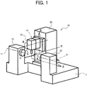
- FIG. 1 illustrates schematically a machine tool to which the present invention is applied.
- FIG. 1 illustrates a double-spindle-opposed turning center 1A in which right and left spindles are laterally opposed to each other.
- FIG. 1 does not illustrate a loading device.
- a workpiece (not shown) is held and rotated by a left spindle 11 and/or a right spindle 31 controlled along a C axis.
- a tool attached to a tool spindle 41 is capable of translational motion along X, Y, and Z axes orthogonal to one another (crossing in a board sense), and is capable of rotational motion around a B axis.
- the spindle 11 is rotatably supported on a headstock 10, and the spindle 31 is rotatably supported on a headstock 30.
- the tool spindle 41 is rotatably supported on a tool post 40.
- a movable carriage 50 is provided in a manner capable of translational motion in the Y- and Z-axis directions with respect to a base 1.
- the tool post 40 is supported movably in the X-axis direction with respect to the movable carriage 50.
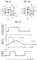
- FIG. 2A illustrates an example of a loading device of the machine tool 1A.
- a loading device 20 is included as auxiliary equipment in the machine tool 1A.
- the loading device 20 includes a chuck 20A that chucks a workpiece W, an arm 20B that supports the chuck 20A, and a movement mechanism 60 (not illustrated in FIG.2A but illustrated in FIGs 3 and 5 ) that moves the arm 20B at least in the X-axis direction and the Z-axis direction.
- the L-shaped chuck (also called first chuck) 20A is turnably coupled to the leading end of the arm 20B by a shaft 24.
- the main chuck 21 is switched between an open state in which the workpiece W can be delivered and a closed state in which the workpiece W is gripped, for example, by widening or narrowing three main chuck jaws 21a in a radial direction.
- the sub chuck 22 also has three sub chuck jaws 22a.
- the main chuck jaws 21a include a sensor, for example, a digital sensor 25a that can continuously detect the fully-open state, the fully-closed state, and the intermediate state.
- the sub chuck jaws 22a also include a digital sensor 25b.
- the main chuck jaws 21a and the sub chuck jaws 22a will be collectively called first chuck jaws.
- the digital sensors 25a and 25b will be collectively called first sensor.
- the spindle 11 is provided with a second chuck 12.
- the second chuck 12 has three second chuck jaws 12a that chuck the workpiece W, for example.
- the second chuck jaws 12a can also be provided with a second sensor, for example, a digital sensor 15 that can continuously detect the fully-open state, the fully-closed state, and the intermediate state.
- FIG. 2A illustrates schematically a state in which the workpiece W is delivered from the main chuck 21 of the loading device 20 to the chuck 12 of the spindle 11.
- FIG. 2B illustrates schematically a state in which the main chuck jaws 21a are slightly opened in an arrow direction B under an instruction for opening the main chuck jaws 21a and the chuck 20A in the loading device 20 starts to move in an arrow direction A1 away from the workpiece W.
- FIG. 2C illustrates a signal for opening and closing the main chuck jaws 21a, the motion of the main chuck jaws 21a, and an movement instruction to a movement mechanism 60.
- the main chuck jaws 21a For example, upon an instructional signal for opening the main chuck jaws 21a, the main chuck jaws 21a starts to change from the fully-closed state to the fully-open state at a time t0 illustrated in FIG. 2C , the main chuck jaws 21a move in opening directions B as illustrated in FIG. 2B . The movement of the main chuck jaws 21a is detected by the digital sensor 25a.
- a movement instruction is output to the movement mechanism 60 so that the chuck 20A in the loading device 20 starts to move in the arrow direction A1 away from the workpiece W as illustrated in FIG. 2B .
- the chuck 20A in the loading device 20 can start to move to the next process at the time t1 earlier than a time t2 when the main chuck jaws 21a reach the open-end position.
- time loss can be reduced by the time (t2 - t1) to shorten the loading time.
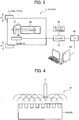
- FIG. 3 illustrates schematically an example of the main chuck 21.
- the main chuck 21 includes a reciprocating drive section, for example, a cylinder 26a and a piston rod 26b that drive the main chuck jaws 21a to an open or closed state, and a dog 27 as a detected section that is provided on the piston rod 26b, for example.
- FIG. 3 does not illustrate a mechanism that transforms orthogonally the reciprocating linear motion of the piston rod 26b into an opening/closing action of the main chuck jaws 21a in the opening/closing directions.
- the main sensor 25a is connected to a controller 100.
- the controller 100 controls the movement mechanism 60.
- the controller 100 outputs the movement instruction to make the chuck 20A to start to move in the Z-axis direction based on an output from the sensor 25a.
- the controller 100 may be connected to a numerical controller (NC) 200 that controls and performs processing of the workpiece W in accordance with a program upon completion of loading action of the loading device 20 based on the signal from the controller 100.
- the NC 200 may be connected to a personal computer (PC) 300, preferably the touch-panel PC.
- the PC 300 can perform data processing, display of processed data, data communication with other devices, and the like.
- FIG. 4 illustrates an example of the main sensor 25a.
- the main sensor 25a illustrated in FIG. 4 forms a magnetic field M by a plurality of coils built in the sensor body over the reciprocating range of the dog 27 to detect continuous changes in the magnetic field depending on the position of the dog 27.
- the main sensor 25a can detect the position of the dog 27 with a positional resolution of 1 mm or less even though the reciprocating range of the dog 27 is as short as 10 to 20 mm, for example.
- the sub chuck 22 of the first chuck 20A can also have the structure illustrated in FIG. 3 and the sub sensor 25b can also have the structure illustrated in FIG. 4 .
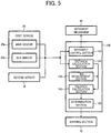
- FIG. 5 is a block diagram of a control system in the machine tool 1A.
- a controller 100 has a movement control section 110 that provides a movement instruction as illustrated in FIG. 2C to a movement mechanism 60 that moves the arm section 20B of the loading device 20 at least in the X- and Z-axis directions.
- the movement control section 110 is connected to the main sensor 25a and the sub sensor 25b constituting the first sensor 25 and the second sensor 15.
- the controller 100 can have a distance calculation section 120 connected to the main sensor 25a and the sub sensor 25b constituting the first sensor 25 and the second sensor 15.
- the distance calculation section 120 calculates the movement distance of the dog 27 provided on one of the first and second chucks 20A and 12 based on the output from one of the first and second sensors 25 and 15.
- the controller 100 can have a time measurement section 130 and a velocity calculation section 140.
- the velocity calculation section 140 accepts an input of time from the time measurement section 130 (for example, times t0, t2, t3, and t4 illustrated in FIG. 2C ) and the distance calculated by the distance calculation section 120 (for example, the distance between the open-end position and closed-end position illustrated in FIG. 2C ).
- the velocity calculation section 140 can calculate the velocity of the dog 27 (for example, velocities V1 and V2 illustrated in FIG. 2C ) provided on one of the first and second chucks 20A and 12 based on the input time and distance.
- the distance calculation section 120 can also detect a scope S of the open-end position or closed-end position illustrated in FIG. 2C .
- the opening and closing motion of the chuck jaws 12a, 21a, and 22a can be continuously detected by the digital sensors 15 and 25, which allows precision control based on the opened and closed positions of the chuck jaws 12a, 21a, and 22a.
- a determination section 150 determines the velocity detected by the velocity calculation section 140 so that it is easy to discover an abnormality in opening and closing of the chuck jaws 12a, 21a, and 22a.
- a warning section 70 connected to the determination section 150 can warn the abnormality by an alarm or the like.
- the determination section 150 can predict the time for parts replacement based on a temporal change of the opening and closing time and notify the time for parts replacement by the warning section 70.
- FIGs. 6A to 8B illustrate examples of actions of the double-spindle-opposed lathe illustrated in FIG. 1 to which the loading device according to the present invention is applied.
- a right spindle 31 illustrated in the drawings includes a chuck 32 with chuck jaws 32a opened or closed.
- the chuck 32 has the same structure as illustrated in FIGs. 3 and 4 .
- the chuck 32 is also provided with a digital sensor.
- the timing chart illustrated in FIG. 2C is also applicable to the actions of chuck jaws 12a, 21a, and 22a described below.
- the spindle 11 and spindle 31 are opposed to each other on a Z-axis line. At least one of the two spindles 11 and 31, for example, the spindle 31 is controlled along the Z-axis direction in forward and backward movements. Referring to FIG. 6A , a workpiece W is held by the main chuck (first chuck) 21 of the loading device 20.
- the workpiece W gripped by the first chuck 21 of the loading device 20 is delivered to the chuck jaws 12a of the second chuck 12 in the spindle 11.
- an instruction for opening the first chuck 21 in the loading device 20 is output at the time t0 illustrated in FIG. 2C .
- the loading device 20 moves in the direction A1 away from the workpiece W as illustrated in FIG. 6C at the time t1 illustrated in FIG. 2C . Further, as illustrated in FIG. 7A , the loading device 20 is evacuated upward.
- the spindle 31 moves forward in an arrow A2 direction as illustrated in FIG. 7A to receive the workpiece W.
- an instruction for closing is output to the chuck 32 of the spindle 31.
- the workpiece W is gripped by the chuck jaws 32a.
- an instruction for opening is output to the chuck jaws 12a of the chuck 12 in the spindle 11.
- the digital sensor 15 in the chuck 12 detects the positions of the chuck jaws 12a during movement from the closed-end position to the open-end position.
- the spindle 32 moves in the arrow A1 direction away from the spindle 11 as illustrated in FIG. 7B at a time t5 illustrated in FIG. 2C . Accordingly, in the same manner as described above, the time for loading the workpiece W from the spindle 11 to the spindle 31 can be shortened. The spindle 31 moves backward to the original position.
- the chuck 20A in the loading device 20 rotates 90° in an arrow D direction around the shaft 24 as illustrated in FIG. 7B .
- the sub chuck 22 with the sub chuck jaws 22a receives the processed workpiece W as illustrated in FIG. 8A .
- the processed workpiece W is conveyed by the loading device 20 as illustrated in FIG. 8B .
- the loading device 20 can move in the direction away from the workpiece W (Z-axis direction) without waiting for the chuck jaws 32a of the chuck 32 to reach the open-end position. Accordingly, the loading time for delivering the workpiece W from the spindle 31 to the loading device 20 can be shortened as well.
- applying the loading device according to the present invention to a machine tool makes it possible to shorten the time for loading the workpiece W and improve productivity.
- the present invention is applied to a double-spindle-opposed lathe in the embodiment but is not limited to this.
- the present invention is also applicable to various machine tools with a loading device.
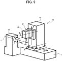
- FIG. 9 illustrates schematically another machine tool to which the present invention is applied.
- FIG. 9 illustrates a single-spindle turning center 1B with the loading device 20 illustrated in FIG. 2A .
- the spindle 11 and the loading device 20 can be provided with the digital sensor illustrated in FIGs. 3 and 4 .
Landscapes
- Engineering & Computer Science (AREA)
- Mechanical Engineering (AREA)
- Human Computer Interaction (AREA)
- Robotics (AREA)
- Feeding Of Workpieces (AREA)
- Turning (AREA)
Applications Claiming Priority (1)
| Application Number | Priority Date | Filing Date | Title |
|---|---|---|---|
| JP2017125402A JP6960659B2 (ja) | 2017-06-27 | 2017-06-27 | 工作機械のローディングシステム |
Publications (2)
| Publication Number | Publication Date |
|---|---|
| EP3441204A1 true EP3441204A1 (de) | 2019-02-13 |
| EP3441204B1 EP3441204B1 (de) | 2023-08-02 |
Family
ID=62750798
Family Applications (1)
| Application Number | Title | Priority Date | Filing Date |
|---|---|---|---|
| EP18179208.6A Active EP3441204B1 (de) | 2017-06-27 | 2018-06-22 | Ladevorrichtung und verfahrenswerkzeug zur verwendung davon |
Country Status (2)
| Country | Link |
|---|---|
| EP (1) | EP3441204B1 (de) |
| JP (1) | JP6960659B2 (de) |
Cited By (1)
| Publication number | Priority date | Publication date | Assignee | Title |
|---|---|---|---|---|
| CN114083010A (zh) * | 2021-02-08 | 2022-02-25 | 常州市润渊精密机械科技有限公司 | 一种带有卡爪位移监测功能的双侧卡盘和卡盘位移监测系统 |
Citations (9)
| Publication number | Priority date | Publication date | Assignee | Title |
|---|---|---|---|---|
| JPS61164755A (ja) * | 1985-01-08 | 1986-07-25 | Mitsubishi Electric Corp | 産業用ロボツトのハンド装置 |
| JPH02243280A (ja) * | 1989-03-14 | 1990-09-27 | Mitsubishi Electric Corp | 産業用ロボットの制御方法 |
| JPH03131488A (ja) * | 1989-10-09 | 1991-06-05 | Murata Mach Ltd | ロボットハンドと物品載置定盤とを有する物品搬送装置 |
| JPH068098A (ja) * | 1992-06-26 | 1994-01-18 | Amada Co Ltd | 板材二枚取り検出装置を備えた板材一枚取り装置 |
| DE29602216U1 (de) * | 1996-02-09 | 1996-04-11 | Fritz Schunk Gmbh, 74348 Lauffen | Greifvorrichtung |
| DE19947997A1 (de) * | 1998-11-07 | 2000-05-25 | Festo Ag & Co | Fluidbetätigter Greifer |
| US6705186B2 (en) * | 2001-09-05 | 2004-03-16 | Yamazaki Mazak Kabushiki Kaisha | Control unit of machine tool |
| JP2005186191A (ja) | 2003-12-25 | 2005-07-14 | Mori Seiki Co Ltd | 工作機械 |
| EP2982474A2 (de) * | 2014-08-08 | 2016-02-10 | Murata Machinery, Ltd. | Werkstückfördervorrichtung und werkzeugmaschine |
Family Cites Families (11)
| Publication number | Priority date | Publication date | Assignee | Title |
|---|---|---|---|---|
| DE3004988C2 (de) * | 1980-02-11 | 1987-10-01 | Gildemeister Ag, 4800 Bielefeld | Vorrichtung zur Einstellung von zwei einen Spannhub begrenzenden Endspannpositionen |
| DE3105872C2 (de) * | 1981-02-18 | 1984-12-06 | Paul Forkardt GmbH & Co KG, 4000 Düsseldorf | Einrichtung zur Bestimmung des Arbeitshubes des Kolbens eines doppeltwirkenden Spannzylinders zur Betätigung von Spanneinrichtungen an Werkzeugmaschinen |
| US4809191A (en) * | 1987-04-28 | 1989-02-28 | Barry Wright Corporation | Robotic position sensor |
| JPH0740102A (ja) * | 1993-07-23 | 1995-02-10 | Murata Mach Ltd | 対向二軸旋盤のローダ装置 |
| JP3293802B2 (ja) * | 1999-07-07 | 2002-06-17 | エスエムシー株式会社 | 位置検出機能付きチャック |
| JP2004050321A (ja) * | 2002-07-17 | 2004-02-19 | Ricoh Co Ltd | ロボットハンドの把持制御方法及び把持装置 |
| JP2006235224A (ja) * | 2005-02-24 | 2006-09-07 | Fuji Photo Film Co Ltd | 撮影装置 |
| CN101558311B (zh) * | 2006-12-04 | 2012-02-08 | 英派克埃彼有限公司 | 带有位置传感器的容器夹持器 |
| DE102010021422A1 (de) * | 2010-05-25 | 2011-12-01 | Günther Zimmer | Greifvorrichtung mit elektrodynamischem Stellglied II |
| DE102015012779A1 (de) * | 2015-10-05 | 2017-04-27 | Günther Zimmer | Greifvorrichtung mit integriertem Servoregler |
| JP6494499B2 (ja) * | 2015-12-09 | 2019-04-03 | 三菱電機株式会社 | 数値制御装置 |
-
2017
- 2017-06-27 JP JP2017125402A patent/JP6960659B2/ja active Active
-
2018
- 2018-06-22 EP EP18179208.6A patent/EP3441204B1/de active Active
Patent Citations (9)
| Publication number | Priority date | Publication date | Assignee | Title |
|---|---|---|---|---|
| JPS61164755A (ja) * | 1985-01-08 | 1986-07-25 | Mitsubishi Electric Corp | 産業用ロボツトのハンド装置 |
| JPH02243280A (ja) * | 1989-03-14 | 1990-09-27 | Mitsubishi Electric Corp | 産業用ロボットの制御方法 |
| JPH03131488A (ja) * | 1989-10-09 | 1991-06-05 | Murata Mach Ltd | ロボットハンドと物品載置定盤とを有する物品搬送装置 |
| JPH068098A (ja) * | 1992-06-26 | 1994-01-18 | Amada Co Ltd | 板材二枚取り検出装置を備えた板材一枚取り装置 |
| DE29602216U1 (de) * | 1996-02-09 | 1996-04-11 | Fritz Schunk Gmbh, 74348 Lauffen | Greifvorrichtung |
| DE19947997A1 (de) * | 1998-11-07 | 2000-05-25 | Festo Ag & Co | Fluidbetätigter Greifer |
| US6705186B2 (en) * | 2001-09-05 | 2004-03-16 | Yamazaki Mazak Kabushiki Kaisha | Control unit of machine tool |
| JP2005186191A (ja) | 2003-12-25 | 2005-07-14 | Mori Seiki Co Ltd | 工作機械 |
| EP2982474A2 (de) * | 2014-08-08 | 2016-02-10 | Murata Machinery, Ltd. | Werkstückfördervorrichtung und werkzeugmaschine |
Cited By (1)
| Publication number | Priority date | Publication date | Assignee | Title |
|---|---|---|---|---|
| CN114083010A (zh) * | 2021-02-08 | 2022-02-25 | 常州市润渊精密机械科技有限公司 | 一种带有卡爪位移监测功能的双侧卡盘和卡盘位移监测系统 |
Also Published As
| Publication number | Publication date |
|---|---|
| JP6960659B2 (ja) | 2021-11-05 |
| EP3441204B1 (de) | 2023-08-02 |
| JP2019005875A (ja) | 2019-01-17 |
Similar Documents
| Publication | Publication Date | Title |
|---|---|---|
| JP4544145B2 (ja) | ロボットの干渉回避方法およびロボット | |
| US4092719A (en) | Autoadaptive working center for programmable automation | |
| KR102547810B1 (ko) | 선반 | |
| CN104289733A (zh) | 定位工件的夹紧装置、带夹紧装置的机床及工件定位方法 | |
| JP6892018B2 (ja) | ロボット装置 | |
| JP6881725B2 (ja) | ワーク加工方法、主軸角度補正装置及び複合旋盤 | |
| JP2018039083A (ja) | 加工システムおよびロボットシステム | |
| CN104281091A (zh) | 具有复合形状固定周期的开始点路径缩短功能的数值控制装置 | |
| CN105563194A (zh) | 一种剪叉机构的自动换刀装置及其模块化的设计方法 | |
| EP3441204A1 (de) | Ladevorrichtung und verfahrenswerkzeug zur verwendung davon | |
| US20240116099A1 (en) | A robotic tube bending machine | |
| US8453545B2 (en) | Machine tool and machining method thereof | |
| JP5439062B2 (ja) | 工作機械の衝突防止方法 | |
| JP2016002601A (ja) | ワーク保持確認装置、及びワーク保持確認方法 | |
| JP2007286688A (ja) | 工作機械の干渉検出方法及び制御装置 | |
| JP2005186212A (ja) | 部品着脱搬送装置 | |
| US20200379438A1 (en) | Numerical control device | |
| CN120187559A (zh) | 数值控制装置以及数值控制系统 | |
| JP7035963B2 (ja) | 搬送装置と工作機械 | |
| JP6983399B2 (ja) | ワーク搬送システム | |
| CN109873526B (zh) | 快速高稳定性垂直运动系统 | |
| CN205325299U (zh) | 一种剪叉机构的自动换刀装置 | |
| KR100299677B1 (ko) | 다관절 로봇의 용접대상물 고속접근장치 및 방법 | |
| JP2023018287A (ja) | 工作機械 | |
| JP2654228B2 (ja) | 数値制御装置 |
Legal Events
| Date | Code | Title | Description |
|---|---|---|---|
| PUAI | Public reference made under article 153(3) epc to a published international application that has entered the european phase |
Free format text: ORIGINAL CODE: 0009012 |
|
| STAA | Information on the status of an ep patent application or granted ep patent |
Free format text: STATUS: THE APPLICATION HAS BEEN PUBLISHED |
|
| AK | Designated contracting states |
Kind code of ref document: A1 Designated state(s): AL AT BE BG CH CY CZ DE DK EE ES FI FR GB GR HR HU IE IS IT LI LT LU LV MC MK MT NL NO PL PT RO RS SE SI SK SM TR |
|
| AX | Request for extension of the european patent |
Extension state: BA ME |
|
| STAA | Information on the status of an ep patent application or granted ep patent |
Free format text: STATUS: REQUEST FOR EXAMINATION WAS MADE |
|
| 17P | Request for examination filed |
Effective date: 20190808 |
|
| RBV | Designated contracting states (corrected) |
Designated state(s): AL AT BE BG CH CY CZ DE DK EE ES FI FR GB GR HR HU IE IS IT LI LT LU LV MC MK MT NL NO PL PT RO RS SE SI SK SM TR |
|
| STAA | Information on the status of an ep patent application or granted ep patent |
Free format text: STATUS: EXAMINATION IS IN PROGRESS |
|
| 17Q | First examination report despatched |
Effective date: 20210111 |
|
| GRAP | Despatch of communication of intention to grant a patent |
Free format text: ORIGINAL CODE: EPIDOSNIGR1 |
|
| STAA | Information on the status of an ep patent application or granted ep patent |
Free format text: STATUS: GRANT OF PATENT IS INTENDED |
|
| INTG | Intention to grant announced |
Effective date: 20230221 |
|
| GRAS | Grant fee paid |
Free format text: ORIGINAL CODE: EPIDOSNIGR3 |
|
| GRAA | (expected) grant |
Free format text: ORIGINAL CODE: 0009210 |
|
| STAA | Information on the status of an ep patent application or granted ep patent |
Free format text: STATUS: THE PATENT HAS BEEN GRANTED |
|
| AK | Designated contracting states |
Kind code of ref document: B1 Designated state(s): AL AT BE BG CH CY CZ DE DK EE ES FI FR GB GR HR HU IE IS IT LI LT LU LV MC MK MT NL NO PL PT RO RS SE SI SK SM TR |
|
| REG | Reference to a national code |
Ref country code: GB Ref legal event code: FG4D |
|
| REG | Reference to a national code |
Ref country code: CH Ref legal event code: EP |
|
| REG | Reference to a national code |
Ref country code: DE Ref legal event code: R096 Ref document number: 602018054405 Country of ref document: DE |
|
| REG | Reference to a national code |
Ref country code: IE Ref legal event code: FG4D |
|
| REG | Reference to a national code |
Ref country code: LT Ref legal event code: MG9D |
|
| REG | Reference to a national code |
Ref country code: NL Ref legal event code: MP Effective date: 20230802 |
|
| REG | Reference to a national code |
Ref country code: AT Ref legal event code: MK05 Ref document number: 1594156 Country of ref document: AT Kind code of ref document: T Effective date: 20230802 |
|
| PG25 | Lapsed in a contracting state [announced via postgrant information from national office to epo] |
Ref country code: GR Free format text: LAPSE BECAUSE OF FAILURE TO SUBMIT A TRANSLATION OF THE DESCRIPTION OR TO PAY THE FEE WITHIN THE PRESCRIBED TIME-LIMIT Effective date: 20231103 |
|
| PG25 | Lapsed in a contracting state [announced via postgrant information from national office to epo] |
Ref country code: IS Free format text: LAPSE BECAUSE OF FAILURE TO SUBMIT A TRANSLATION OF THE DESCRIPTION OR TO PAY THE FEE WITHIN THE PRESCRIBED TIME-LIMIT Effective date: 20231202 |
|
| PG25 | Lapsed in a contracting state [announced via postgrant information from national office to epo] |
Ref country code: SE Free format text: LAPSE BECAUSE OF FAILURE TO SUBMIT A TRANSLATION OF THE DESCRIPTION OR TO PAY THE FEE WITHIN THE PRESCRIBED TIME-LIMIT Effective date: 20230802 Ref country code: RS Free format text: LAPSE BECAUSE OF FAILURE TO SUBMIT A TRANSLATION OF THE DESCRIPTION OR TO PAY THE FEE WITHIN THE PRESCRIBED TIME-LIMIT Effective date: 20230802 Ref country code: PT Free format text: LAPSE BECAUSE OF FAILURE TO SUBMIT A TRANSLATION OF THE DESCRIPTION OR TO PAY THE FEE WITHIN THE PRESCRIBED TIME-LIMIT Effective date: 20231204 Ref country code: NO Free format text: LAPSE BECAUSE OF FAILURE TO SUBMIT A TRANSLATION OF THE DESCRIPTION OR TO PAY THE FEE WITHIN THE PRESCRIBED TIME-LIMIT Effective date: 20231102 Ref country code: NL Free format text: LAPSE BECAUSE OF FAILURE TO SUBMIT A TRANSLATION OF THE DESCRIPTION OR TO PAY THE FEE WITHIN THE PRESCRIBED TIME-LIMIT Effective date: 20230802 Ref country code: LV Free format text: LAPSE BECAUSE OF FAILURE TO SUBMIT A TRANSLATION OF THE DESCRIPTION OR TO PAY THE FEE WITHIN THE PRESCRIBED TIME-LIMIT Effective date: 20230802 Ref country code: LT Free format text: LAPSE BECAUSE OF FAILURE TO SUBMIT A TRANSLATION OF THE DESCRIPTION OR TO PAY THE FEE WITHIN THE PRESCRIBED TIME-LIMIT Effective date: 20230802 Ref country code: IS Free format text: LAPSE BECAUSE OF FAILURE TO SUBMIT A TRANSLATION OF THE DESCRIPTION OR TO PAY THE FEE WITHIN THE PRESCRIBED TIME-LIMIT Effective date: 20231202 Ref country code: HR Free format text: LAPSE BECAUSE OF FAILURE TO SUBMIT A TRANSLATION OF THE DESCRIPTION OR TO PAY THE FEE WITHIN THE PRESCRIBED TIME-LIMIT Effective date: 20230802 Ref country code: GR Free format text: LAPSE BECAUSE OF FAILURE TO SUBMIT A TRANSLATION OF THE DESCRIPTION OR TO PAY THE FEE WITHIN THE PRESCRIBED TIME-LIMIT Effective date: 20231103 Ref country code: FI Free format text: LAPSE BECAUSE OF FAILURE TO SUBMIT A TRANSLATION OF THE DESCRIPTION OR TO PAY THE FEE WITHIN THE PRESCRIBED TIME-LIMIT Effective date: 20230802 Ref country code: AT Free format text: LAPSE BECAUSE OF FAILURE TO SUBMIT A TRANSLATION OF THE DESCRIPTION OR TO PAY THE FEE WITHIN THE PRESCRIBED TIME-LIMIT Effective date: 20230802 |
|
| PG25 | Lapsed in a contracting state [announced via postgrant information from national office to epo] |
Ref country code: PL Free format text: LAPSE BECAUSE OF FAILURE TO SUBMIT A TRANSLATION OF THE DESCRIPTION OR TO PAY THE FEE WITHIN THE PRESCRIBED TIME-LIMIT Effective date: 20230802 |
|
| PG25 | Lapsed in a contracting state [announced via postgrant information from national office to epo] |
Ref country code: ES Free format text: LAPSE BECAUSE OF FAILURE TO SUBMIT A TRANSLATION OF THE DESCRIPTION OR TO PAY THE FEE WITHIN THE PRESCRIBED TIME-LIMIT Effective date: 20230802 |
|
| PG25 | Lapsed in a contracting state [announced via postgrant information from national office to epo] |
Ref country code: SM Free format text: LAPSE BECAUSE OF FAILURE TO SUBMIT A TRANSLATION OF THE DESCRIPTION OR TO PAY THE FEE WITHIN THE PRESCRIBED TIME-LIMIT Effective date: 20230802 Ref country code: RO Free format text: LAPSE BECAUSE OF FAILURE TO SUBMIT A TRANSLATION OF THE DESCRIPTION OR TO PAY THE FEE WITHIN THE PRESCRIBED TIME-LIMIT Effective date: 20230802 Ref country code: ES Free format text: LAPSE BECAUSE OF FAILURE TO SUBMIT A TRANSLATION OF THE DESCRIPTION OR TO PAY THE FEE WITHIN THE PRESCRIBED TIME-LIMIT Effective date: 20230802 Ref country code: EE Free format text: LAPSE BECAUSE OF FAILURE TO SUBMIT A TRANSLATION OF THE DESCRIPTION OR TO PAY THE FEE WITHIN THE PRESCRIBED TIME-LIMIT Effective date: 20230802 Ref country code: DK Free format text: LAPSE BECAUSE OF FAILURE TO SUBMIT A TRANSLATION OF THE DESCRIPTION OR TO PAY THE FEE WITHIN THE PRESCRIBED TIME-LIMIT Effective date: 20230802 Ref country code: CZ Free format text: LAPSE BECAUSE OF FAILURE TO SUBMIT A TRANSLATION OF THE DESCRIPTION OR TO PAY THE FEE WITHIN THE PRESCRIBED TIME-LIMIT Effective date: 20230802 Ref country code: SK Free format text: LAPSE BECAUSE OF FAILURE TO SUBMIT A TRANSLATION OF THE DESCRIPTION OR TO PAY THE FEE WITHIN THE PRESCRIBED TIME-LIMIT Effective date: 20230802 |
|
| REG | Reference to a national code |
Ref country code: DE Ref legal event code: R097 Ref document number: 602018054405 Country of ref document: DE |
|
| PG25 | Lapsed in a contracting state [announced via postgrant information from national office to epo] |
Ref country code: IT Free format text: LAPSE BECAUSE OF FAILURE TO SUBMIT A TRANSLATION OF THE DESCRIPTION OR TO PAY THE FEE WITHIN THE PRESCRIBED TIME-LIMIT Effective date: 20230802 |
|
| PLBE | No opposition filed within time limit |
Free format text: ORIGINAL CODE: 0009261 |
|
| STAA | Information on the status of an ep patent application or granted ep patent |
Free format text: STATUS: NO OPPOSITION FILED WITHIN TIME LIMIT |
|
| 26N | No opposition filed |
Effective date: 20240503 |
|
| PG25 | Lapsed in a contracting state [announced via postgrant information from national office to epo] |
Ref country code: SI Free format text: LAPSE BECAUSE OF FAILURE TO SUBMIT A TRANSLATION OF THE DESCRIPTION OR TO PAY THE FEE WITHIN THE PRESCRIBED TIME-LIMIT Effective date: 20230802 |
|
| PG25 | Lapsed in a contracting state [announced via postgrant information from national office to epo] |
Ref country code: BG Free format text: LAPSE BECAUSE OF FAILURE TO SUBMIT A TRANSLATION OF THE DESCRIPTION OR TO PAY THE FEE WITHIN THE PRESCRIBED TIME-LIMIT Effective date: 20230802 |
|
| PG25 | Lapsed in a contracting state [announced via postgrant information from national office to epo] |
Ref country code: BG Free format text: LAPSE BECAUSE OF FAILURE TO SUBMIT A TRANSLATION OF THE DESCRIPTION OR TO PAY THE FEE WITHIN THE PRESCRIBED TIME-LIMIT Effective date: 20230802 |
|
| PG25 | Lapsed in a contracting state [announced via postgrant information from national office to epo] |
Ref country code: MC Free format text: LAPSE BECAUSE OF FAILURE TO SUBMIT A TRANSLATION OF THE DESCRIPTION OR TO PAY THE FEE WITHIN THE PRESCRIBED TIME-LIMIT Effective date: 20230802 |
|
| REG | Reference to a national code |
Ref country code: CH Ref legal event code: PL |
|
| PG25 | Lapsed in a contracting state [announced via postgrant information from national office to epo] |
Ref country code: LU Free format text: LAPSE BECAUSE OF NON-PAYMENT OF DUE FEES Effective date: 20240622 |
|
| GBPC | Gb: european patent ceased through non-payment of renewal fee |
Effective date: 20240622 |
|
| PG25 | Lapsed in a contracting state [announced via postgrant information from national office to epo] |
Ref country code: IE Free format text: LAPSE BECAUSE OF NON-PAYMENT OF DUE FEES Effective date: 20240622 |
|
| PG25 | Lapsed in a contracting state [announced via postgrant information from national office to epo] |
Ref country code: CH Free format text: LAPSE BECAUSE OF NON-PAYMENT OF DUE FEES Effective date: 20240630 Ref country code: BE Free format text: LAPSE BECAUSE OF NON-PAYMENT OF DUE FEES Effective date: 20240630 |
|
| PG25 | Lapsed in a contracting state [announced via postgrant information from national office to epo] |
Ref country code: FR Free format text: LAPSE BECAUSE OF NON-PAYMENT OF DUE FEES Effective date: 20240630 |
|
| PG25 | Lapsed in a contracting state [announced via postgrant information from national office to epo] |
Ref country code: GB Free format text: LAPSE BECAUSE OF NON-PAYMENT OF DUE FEES Effective date: 20240622 |
|
| REG | Reference to a national code |
Ref country code: BE Ref legal event code: MM Effective date: 20240630 |
|
| PGFP | Annual fee paid to national office [announced via postgrant information from national office to epo] |
Ref country code: DE Payment date: 20250618 Year of fee payment: 8 |
|
| PG25 | Lapsed in a contracting state [announced via postgrant information from national office to epo] |
Ref country code: CY Free format text: LAPSE BECAUSE OF FAILURE TO SUBMIT A TRANSLATION OF THE DESCRIPTION OR TO PAY THE FEE WITHIN THE PRESCRIBED TIME-LIMIT; INVALID AB INITIO Effective date: 20180622 |
|
| PG25 | Lapsed in a contracting state [announced via postgrant information from national office to epo] |
Ref country code: HU Free format text: LAPSE BECAUSE OF FAILURE TO SUBMIT A TRANSLATION OF THE DESCRIPTION OR TO PAY THE FEE WITHIN THE PRESCRIBED TIME-LIMIT; INVALID AB INITIO Effective date: 20180622 |