EP3440402B1 - Beleuchtungsvorrichtung für ein fahrzeug - Google Patents
Beleuchtungsvorrichtung für ein fahrzeug Download PDFInfo
- Publication number
- EP3440402B1 EP3440402B1 EP17712465.8A EP17712465A EP3440402B1 EP 3440402 B1 EP3440402 B1 EP 3440402B1 EP 17712465 A EP17712465 A EP 17712465A EP 3440402 B1 EP3440402 B1 EP 3440402B1
- Authority
- EP
- European Patent Office
- Prior art keywords
- light
- light emission
- emission element
- cavity
- light guide
- Prior art date
- Legal status (The legal status is an assumption and is not a legal conclusion. Google has not performed a legal analysis and makes no representation as to the accuracy of the status listed.)
- Active
Links
Images

Classifications
-
- B—PERFORMING OPERATIONS; TRANSPORTING
- B60—VEHICLES IN GENERAL
- B60Q—ARRANGEMENT OF SIGNALLING OR LIGHTING DEVICES, THE MOUNTING OR SUPPORTING THEREOF OR CIRCUITS THEREFOR, FOR VEHICLES IN GENERAL
- B60Q3/00—Arrangement of lighting devices for vehicle interiors; Lighting devices specially adapted for vehicle interiors
- B60Q3/60—Arrangement of lighting devices for vehicle interiors; Lighting devices specially adapted for vehicle interiors characterised by optical aspects
- B60Q3/62—Arrangement of lighting devices for vehicle interiors; Lighting devices specially adapted for vehicle interiors characterised by optical aspects using light guides
- B60Q3/64—Arrangement of lighting devices for vehicle interiors; Lighting devices specially adapted for vehicle interiors characterised by optical aspects using light guides for a single lighting device
-
- B—PERFORMING OPERATIONS; TRANSPORTING
- B60—VEHICLES IN GENERAL
- B60Q—ARRANGEMENT OF SIGNALLING OR LIGHTING DEVICES, THE MOUNTING OR SUPPORTING THEREOF OR CIRCUITS THEREFOR, FOR VEHICLES IN GENERAL
- B60Q3/00—Arrangement of lighting devices for vehicle interiors; Lighting devices specially adapted for vehicle interiors
- B60Q3/60—Arrangement of lighting devices for vehicle interiors; Lighting devices specially adapted for vehicle interiors characterised by optical aspects
-
- B—PERFORMING OPERATIONS; TRANSPORTING
- B60—VEHICLES IN GENERAL
- B60Q—ARRANGEMENT OF SIGNALLING OR LIGHTING DEVICES, THE MOUNTING OR SUPPORTING THEREOF OR CIRCUITS THEREFOR, FOR VEHICLES IN GENERAL
- B60Q3/00—Arrangement of lighting devices for vehicle interiors; Lighting devices specially adapted for vehicle interiors
- B60Q3/70—Arrangement of lighting devices for vehicle interiors; Lighting devices specially adapted for vehicle interiors characterised by the purpose
- B60Q3/76—Arrangement of lighting devices for vehicle interiors; Lighting devices specially adapted for vehicle interiors characterised by the purpose for spotlighting, e.g. reading lamps
-
- F—MECHANICAL ENGINEERING; LIGHTING; HEATING; WEAPONS; BLASTING
- F21—LIGHTING
- F21S—NON-PORTABLE LIGHTING DEVICES; SYSTEMS THEREOF; VEHICLE LIGHTING DEVICES SPECIALLY ADAPTED FOR VEHICLE EXTERIORS
- F21S43/00—Signalling devices specially adapted for vehicle exteriors, e.g. brake lamps, direction indicator lights or reversing lights
- F21S43/10—Signalling devices specially adapted for vehicle exteriors, e.g. brake lamps, direction indicator lights or reversing lights characterised by the light source
- F21S43/13—Signalling devices specially adapted for vehicle exteriors, e.g. brake lamps, direction indicator lights or reversing lights characterised by the light source characterised by the type of light source
- F21S43/14—Light emitting diodes [LED]
-
- G—PHYSICS
- G02—OPTICS
- G02B—OPTICAL ELEMENTS, SYSTEMS OR APPARATUS
- G02B6/00—Light guides; Structural details of arrangements comprising light guides and other optical elements, e.g. couplings
- G02B6/0001—Light guides; Structural details of arrangements comprising light guides and other optical elements, e.g. couplings specially adapted for lighting devices or systems
- G02B6/0011—Light guides; Structural details of arrangements comprising light guides and other optical elements, e.g. couplings specially adapted for lighting devices or systems the light guides being planar or of plate-like form
- G02B6/0013—Means for improving the coupling-in of light from the light source into the light guide
- G02B6/0023—Means for improving the coupling-in of light from the light source into the light guide provided by one optical element, or plurality thereof, placed between the light guide and the light source, or around the light source
- G02B6/0028—Light guide, e.g. taper
Definitions
- the invention relates to a lighting device for a vehicle, which has a light source, a line-shaped light-emitting element for emitting light that is fed from the light source via a coupling surface of the light-emitting element into the light-emitting element, and a light guide element for the distribution and / or direction of light emitted by the light emitting element is fed into the light guide element.
- the invention also relates to an interior trim part.
- contour line lighting for the interior lighting of a vehicle, which primarily serves the purpose of accent lighting.
- the DE 10 2012 015 057 A1 comprises a lighting device for a vehicle which comprises a light source and a surface light guide, the light emission of the light source being coupled into the surface light guide via an end face of a surface light guide designed as a light coupling surface.
- an interior trim part for a vehicle which comprises a light guide fed by a light source for emitting light and a strip-shaped light guide element.
- the light guide element has a first and a second surface, the first surface being one of the two largest surfaces of the light guide element.
- the second surface is a different surface and comprises a coupling surface.
- the light guide element and the essentially circular light guide are arranged and configured such that light from the light guide can be coupled into the light guide element via the coupling surface in the planar first surface and can be coupled out via the second surface. This provides point and line lighting with small dimensions.
- the EP 2 530 503 A1 discloses a lighting device with a rod-shaped light guide and a light source for feeding light into the light guide.
- the rod-shaped light guide has a strip extending in a longitudinal direction with a light-refracting / scattering structure for generating a main direction of light in the sense of an enlarged image of the structure for the viewer due to the curvature of the light guide cross-section.
- the light is emitted essentially via a circular arc-shaped exit surface.
- the circular arc-shaped exit surface lies essentially opposite the strip with the light-refracting / dispersing structure.
- Light is coupled in at the end face or faces of the rod-shaped light guide.
- the light source can be used to regulate the brightness between 0 and 100%, but the brightness of the light guide is always constant over its length.
- the light color emitted by the light source it is also possible to achieve a specific color effect that is also constant over the length of the light guide.
- the US 2014/0321139 A1 discloses a lighting device for a vehicle, which has a light source, a line-shaped light-emitting element for emitting light that is fed from the light source via a coupling surface of the light-emitting element into the light-emitting element, and a light guide element for distributing and / or directing light emitted by the light-emitting element is fed into the light guide element comprises.
- the light-emitting element is arranged at least partially in a cavity of the light guide element, which is open on one side, in such a way that they are at a predetermined distance from one another.
- the DE 10 2010 012 745 A1 discloses a lighting device for a vehicle comprising a light source, a line-shaped light emitting element for emitting light and a light guide element for distributing and / or directing light fed from the light emitting element into the light guide element.
- the light-emitting element has a plurality of decoupling elements on a side facing away from the light guide element on, wherein the light guide element comprises light entry surfaces on these opposite points, which can be formed as indentations open on one side.
- the EP 2 143 991 A2 discloses a lighting device in which a light source comprises a carrier with a plurality of LEDs arranged thereon.
- the carrier is mechanically connected to a light guide element.
- the US 2010/0027256 A1 discloses a lighting device in which a light source is arranged in a cavity of a light-emitting element, which is open on one side.
- the DE 10 2013 104 169 A1 discloses a lighting device, the light guide of which comprises a cavity that is open on one side. An additional light guide protrudes into the cavity in sections, a distance being formed between the light guide and the additional light guide.
- the object of the invention is to specify a lighting device for a vehicle and an interior trim part which are structurally and / or functionally improved compared to the solutions known from the prior art.
- a lighting device for a vehicle and an interior trim part which are structurally and / or functionally improved compared to the solutions known from the prior art.
- the invention proposes a lighting device for a vehicle, which has a light source, a line-shaped light-emitting element for emitting light that is fed from the light source via a coupling surface of the light-emitting element into the light-emitting element, and a light guide element, for example in the form of a diffuser, for distribution and / or the direction of light which is fed from the light-emitting element into the light guide element.
- the light source is linear and is arranged to run parallel to the light-emitting element, so that light from the light source is on a longitudinal side of the light-emitting element can be coupled into the coupling surface in the light-emitting element.
- the light-emitting element is arranged at least partially in a cavity of the light guide element that is open on one side.
- the lighting device is characterized in that the light-emitting element is held non-positively and / or positively and can be detached from the light guide element in a non-destructive manner. Furthermore, the light-emitting element is interchangeable with a light-emitting element which is circular or elliptical in cross section perpendicular to the direction of extent and in which a point light source is arranged on at least one end face of the light-emitting element.
- the cavity provides a mechanical receptacle for the light-emitting element and the light source assigned to the light-emitting element.
- the light-emitting element can be "clipped" into the cavity, with the light-emitting element being held securely by a force fit and / or form fit.
- the light source is linear, so that light can be coupled laterally into the light-emitting element at least over a section of the longitudinal extent of the light-emitting element. This makes it possible to achieve dynamic lighting effects or lighting scenarios with the aid of the lighting device according to the invention.
- the light-emitting element can be detached from the cavity serving as a receptacle without being destroyed, a simpler combination of linear light-emitting element and light source can easily be arranged in the cavity.
- the light source can only comprise a single light-emitting element which feeds light into the end face of the light-emitting element.
- the light guide element can be configured as a common component. It is thus possible to sell the high-quality variant with the linear light-emitting element as special equipment, while the simpler variant with a single light unit of the light source can be kept for simpler equipment variants of a vehicle. There is also the possibility of replacing the linear light-emitting element including the light source to provide the lighting device with higher quality equipment at a later point in time.
- the light-emitting element is connected to the light source to form a light module, the light module being detachable from the light guide element in a non-destructive manner.
- the lighting device can be easily equipped with either a simple light module or a high-quality light module.
- the simple light module comprises a line-shaped light-emitting element with one or two light units of the light source on the end faces of the light-emitting element.
- the high-quality light module comprises the line-shaped light-emitting element and the line-shaped light source, in particular with a plurality of light units, which are arranged to run parallel to the light-emitting element.
- the cavity has a circular arc shape in a cross section perpendicular to the direction of extent of the light guide element, at least in sections, the circular arc section forming a concave light entry surface of the light guide element for light exiting from the light emission element.
- the circular-arc shape of the cavity takes into account the fact that light-emitting elements of a simple light module generally have an essentially circular cross-section. This is necessary in order to be able to direct the light fed in at the end face or faces out of the light-emitting element via imperfections along the light-emitting element transversely to its longitudinal extension.
- the circular arc-shaped shape of the cavity thus enables good mechanical retention and simple installation of the light-emitting element in the light-emitting element, although the circular-arc-shaped cross-sectional shape is more of a disadvantage for reasons of light propagation.
- the light emission element has, at least in sections, a circular arc shape in a cross section perpendicular to its direction of extension, the circular arc section having a convex coupling-out surface for from the Light emitting element forms emerging light.
- the concave light entry surface of the light guide element and the convex outcoupling surface of the light emission element are adapted to one another so that they adjoin one another - nestling closely together - when the light emission element is arranged in the cavity of the light guide element.
- this configuration also ensures that the light-emitting element can be clipped into the cavity of the light guide element in a simple and fault-tolerant manner.
- the cross-sectional shape of the light-emitting element is adapted to the shape of the cavity in a cross-section perpendicular to its direction of extension, the cross-sectional shape of the light-emitting element outside the cavity being dependent on the design and arrangement of the light source.
- the adaptation of the cross-sectional shapes of different light-emitting elements to the shape of the cavity enables, regardless of the design of the cross-sectional shape of the respective light-emitting elements outside the cavity, its frictional and / or form-fitting mounting as well as a loss-free and directional coupling of light into the light guide element.
- the light-emitting element has a first length extension and a length extension that is greater than the first length extension in a cross section perpendicular to the direction of extension, the first length extension extending along the chord of the circular arc and the second length extension extending transversely thereto. Due to the shape of the light-emitting element of a high-quality light module, which is elongated in cross section, a good mixture of different colors, which are emitted by one or more light units, can already be achieved within the light-emitting element. It is irrelevant how the light source and the number of light units are arranged in relation to the opening of the cavity.
- the unit of light-emitting element and light source represents the already mentioned simple light module, which according to the invention is against the high-quality light module described above can be easily exchanged.
- the arc length of the circular arc of the cavity is greater than half the outer circumference of the circle defining the circular arc. This ensures that the light-emitting element can be held non-positively and / or positively in the cavity of the light guide element, since the ends of the light guide element forming the cavity at least slightly enclose the light-emitting element.
- the light-emitting element In order to simplify production and to avoid damage when the light-emitting element is introduced into the cavity, it is expedient to form the light-emitting element from a flexible material.
- the light guide element is designed in one piece with a decorative element made of light-tight material.
- the light guide element which can for example be made of translucent light-diffusing material such as polycarbonate, can be provided with the trim strip made of light-tight material, for example black or chrome-plated ABS plastic, by means of a two-component injection molding process.
- the invention also proposes an interior trim part for a vehicle which comprises a lighting device of the lighting device reproduced in this description.
- the interior trim part has the same advantages as those described above in connection with the lighting device.
- the interior trim part expediently comprises a decorative element in the form of the decorative element.
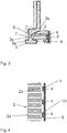
- FIGS. 1 and 2 show a first embodiment of a lighting device according to the invention for a vehicle, which is used as an interior trim part, for example on the inside of the doors, for the vehicle.
- Fig. 1 shows a section through the lighting device
- Fig. 2 a side view of a light module used in the lighting device according to a first, simple variant.
- the lighting device comprises a linear light-emitting element 2, a diffuser element 3 as a light guide element and a decorative or decorative element 7.
- the light-emitting element 2, the diffuser element 3 and the decorative element 7 extend parallel in FIG Fig. 1 into the plane of the drawing.
- the light-emitting element 2 here has, for example, an essentially circular cross section. It consists of a plastic, e.g. PMMA, or glass and is clear or partially transparent.
- the light-emitting element 2 lies in a cavity 8 of the lens element 3.
- the cavity 8 has an arcuate shape at least in sections, the arc-shaped segment 9 forming a concave light entry surface 3e of the lens element 3 for light exiting from the light-emitting element 2.
- the part of the light-emitting element 2 lying in the interior of the cavity 8 has a shape adapted to the shape of the cavity 8. This means that the part of the light-emitting element 2 lying in the cavity 8 also has a shape that is at least partially in the shape of a circular arc.
- the light outcoupling surface 2a of the light emission element 2 and the light entry surface 3e of the light guide element 3 are closely adjacent, so that a targeted and predictable coupling of the light emerging from the light emission element 2 into the diffuser element 3 is ensured.
- the arc length of the circular arc of the cavity 8 is greater than half the outer circumference of the circle defining the circular arc, so that the cavity 8 encloses the light-emitting element 2 in such a way that the light module is held positively and / or positively. Due to the flexibility of the material of the lens element 3, the light-emitting element 2 can be detachably removed from the cavity without destroying or damaging the lens element 3 in the process.
- the in Fig. 2 The simple light module shown, which represents a unit of the light-emitting element 2 and the light source 1, the light source 1 has a single light unit 4, for example in the form of a light-emitting diode (LED).
- the lighting unit 4 in the form of the light-emitting diode is arranged on a carrier 5. This unit is in turn connected to a free end of the light-emitting element 2 via a housing 6, so that light can be coupled in at the end face of the light-emitting element 2.
- the Figures 3 and 4 show a second exemplary embodiment of a lighting device according to the invention, only the light module comprising the light-emitting element 2 and the light source 1 being compared with the simple light module from the exemplary embodiment in FIG Fig. 1 is modified. It is made possible to replace the simple light module of the first exemplary embodiment according to FIG Fig. 2 thanks to the higher quality light module according to Figures 3 and 4 due to the shape of the light-emitting element 2, which is here essentially elongated in cross-section, likewise in sections, it is possible to clip the light-emitting element 2 of the second variant into the cavity 8, the arc-shaped section that forms the light outcoupling surface 2a being attached to the light entry surface 3e of the Cavity 8 of the lens element 3 is adjacent. A substantial part of the light-emitting element 2 is arranged outside the cavity.
- the light source 1 in the second embodiment is linear and is arranged to run parallel to the light-emitting element 2, so that light from the light source 1 can be coupled into the coupling-in surface 2e of the light-emitting element 2 on a longitudinal side of the light-emitting element 2.
- the light source 1 lies opposite the opening of the cavity 8, although a lateral arrangement would also be conceivable.
- Fig. 4 shows a sectional plan view of the light module of FIG Fig. 3 . It can be seen here that by way of example three lighting elements 4 are arranged on a carrier 5.
- the light-emitting elements 4 come to rest in recesses 10 of the light-emitting element 2 in order to couple light into the light-emitting element 2 here.
- the decorative element 7 consists in both variants of a light-proof material, e.g. a black or chrome-plated ABS plastic.
- the decorative element 7 can be formed together with the diffuser element 3, which is formed from a translucent, light-diffusing material such as polycarbonate, in a two-component injection molding process.
- An invariable decorative screen which comprises the decorative element 7 and the lens element 3, can be used.
- the interchangeability of the light module makes it possible to replace a simple light module with a higher-quality light module at a later point in time. This enables a modular principle to be implemented.
Landscapes
- Engineering & Computer Science (AREA)
- Physics & Mathematics (AREA)
- Mechanical Engineering (AREA)
- Optics & Photonics (AREA)
- General Physics & Mathematics (AREA)
- Microelectronics & Electronic Packaging (AREA)
- General Engineering & Computer Science (AREA)
- Arrangements Of Lighting Devices For Vehicle Interiors, Mounting And Supporting Thereof, Circuits Therefore (AREA)
Description
- Die Erfindung betrifft eine Beleuchtungsvorrichtung für ein Fahrzeug, das eine Lichtquelle, ein linienförmiges Lichtemissionselement zum Emittieren von Licht, das von der Lichtquelle über eine Einkopplungsfläche des Lichtemissionselements in das Lichtemissionselement gespeist wird, und ein Lichtleiterelement zur Verteilung und/oder Richtung von Licht, das von dem Lichtemissionselement in das Lichtleiterelement gespeist wird, umfasst. Die Erfindung betrifft ferner ein Innenausstattungsteil.
- Es ist bekannt, für die Innenraumbeleuchtung eines Fahrzeugs eine Konturlinienbeleuchtung zu verwenden, welche primär den Zweck einer Akzentbeleuchtung erfüllt.
- Die
DE 10 2012 015 057 A1 umfasst eine Beleuchtungsvorrichtung für ein Fahrzeug, das eine Lichtquelle und einen Flächenlichtleiter umfasst, wobei die Lichtemission der Lichtquelle über eine als Lichteinkopplungsfläche ausgebildete Stirnfläche eines Flächenlichtleiters in den Flächenlichtleiter eingekoppelt wird. - Aus der
DE 10 2010 030 660 A1 ist ein Innenausstattungsteil für ein Fahrzeug bekannt, das einen von einer Lichtquelle gespeisten Lichtleiter zum Emittieren von Licht und ein streifenförmiges Lichtleiterelement umfasst. Das Lichtleiterelement weist eine erste und eine zweite Oberfläche auf, wobei die erste Oberfläche eine der beiden größten Oberflächen des Lichtleiterelements ist. Die zweite Oberfläche ist eine von diesem abweichende Oberfläche und umfasst eine Einkopplungsfläche. Das Lichtleiterelement und der im Wesentlichen kreisrunde Lichtleiter sind so angeordnet und ausgestaltet, dass Licht von dem Lichtleiter über die Einkopplungsfläche in der ebenen ersten Oberfläche in das Lichtleiterelement einkoppelbar und über die zweite Oberfläche auskoppelbar ist. Dadurch wird eine Punkt- und Linienbeleuchtung mit geringen Ausmaßen bereitgestellt. - Die
EP 2 530 503 A1 offenbart eine Beleuchtungseinrichtung mit einem stabförmigen Lichtleiter und einer Lichtquelle zur Lichteinspeisung in den Lichtleiter. Der stabförmige Lichtleiter weist einen, sich in einer Längsrichtung erstreckenden Streifen mit einer lichtbrechenden/zerstreuenden Strukturierung zur Erzeugung einer Hauptlichtrichtung im Sinne einer für den Betrachter durch die Krümmung des Lichtleiterquerschnitts vergrößerten Abbildung der Strukturierung auf. Der Lichtaustritt erfolgt über eine im Wesentlichen kreisbogenförmige Austrittsfläche. Die kreisbogenförmige Austrittsfläche liegt im Wesentlichen gegenüber dem Streifen mit der lichtbrechenden/zerstreuenden Strukturierung. Eine Lichteinkopplung erfolgt an der oder den Stirnseiten des stabförmigen Lichtleiters. - Bei diesen Beleuchtungsvorrichtungen sind lediglich statische Lichteffekte möglich, d.h. mittels der Lichtquelle kann die Helligkeit zwischen 0 und 100 % reguliert werden, wobei die Helligkeit des Lichtleiters über dessen Länge jedoch immer konstant ist. In Abhängigkeit der von der Lichtquelle abgegebenen Lichtfarbe ist es darüber hinaus möglich, einen bestimmten Farbeffekt zu erzielen, der ebenfalls über die Länge des Lichtleiters konstant ist.
- Für eine erweitere Lichtinszenierung ist es erforderlich, eine Konturlinie mit mehreren Lichtquellen zeitlich veränderlich zu hinterleuchten. Die Integration von mehreren Lichtquellen ist jedoch teurer und aufwändiger als die eingangs beschriebene Lösung mit einem oder zwei an den stirnseitigen Enden des Lichtemissionselements angebrachten Lichtquellen. Darüber hinaus benötigt eine Beleuchtungsvorrichtung mit mehreren Lichtquellen einen anderen Aufbau als die einfache Variante mit lediglich einer oder zwei Lichtquellen an den stirnseitigen Enden des Lichtemissionselements. Das Erfordernis unterschiedlicher Bauteilvarianten ist jedoch aus Kostengründen unerwünscht.
- Die
US 2014/0321139 A1 offenbart eine Beleuchtungsvorrichtung für ein Fahrzeug, das eine Lichtquelle, ein linienförmiges Lichtemissionselement zum Emittieren von Licht, das von der Lichtquelle über eine Einkopplungsfläche des Lichtemissionselement in das Lichtemissionselement gespeist wird, und ein Lichtleiterelement zur Verteilung und/oder Richtung von Licht, das von dem Lichtemissionselement in das Lichtleiterelement gespeist wird, umfasst. Das Lichtemissionselement ist zumindest teilweise in einer einseitig offenen Kavität des Lichtleiterelements derart angeordnet, dass diese einen vorgegebenen Abstand zueinander aufweisen. - Die
DE 10 2010 012 745 A1 offenbart eine Beleuchtungsvorrichtung für ein Fahrzeug, das eine Lichtquelle, ein linienförmiges Lichtemissionselement zum Emittieren von Licht und ein Lichtleiterelement zur Verteilung und/oder Richtung von Licht, das von dem Lichtemissionselement in das Lichtleiterelement gespeist wird, umfasst. Das Lichtemissionselement weist an einer dem Lichtleiterelement abgewandten Seite mehrere Auskoppelelemente auf, wobei das Lichtleiterelement auf diesen gegenüberliegenden Stellen Lichteintrittsflächen umfasst, die als einseitig offene Einformungen ausgebildet sein können. - Die
EP 2 143 991 A2 offenbart eine Beleuchtungsvorrichtung, bei der eine Lichtquelle einen Träger mit einer Mehrzahl darauf angeordneter LEDs umfasst. Der Träger ist mechanisch mit einem Lichtleiterelement verbunden. - Die
US 2010/0027256 A1 offenbart eine Beleuchtungsvorrichtung, bei der eine Lichtquelle in einer einseitig offenen Kavität eines Lichtemissionselement angeordnet ist. - Die
DE 10 2013 104 169 A1 offenbart eine Beleuchtungsvorrichtung, dessen Lichtleiter eine einseitig offene Kavität umfasst. Ein Zusatzlichtleiter ragt abschnittsweise in die Kavität hinein, wobei ein Abstand zwischen Lichtleiter und Zusatzlichtleiter gebildet ist. - Es ist Aufgabe der Erfindung, eine Beleuchtungsvorrichtung für ein Fahrzeug sowie ein Innenausstattungsteil anzugeben, welche baulich und/oder funktional gegenüber den aus dem Stand der Technik bekannten Lösungen verbessert sind. Insbesondere soll unabhängig von der Anzahl der in einer Beleuchtungsvorrichtung verbauten Lichtquellen auf eine möglichst große Anzahl an Gleichbauteilen zurückgegriffen werden können.
- Diese Aufgaben werden gelöst durch eine Beleuchtungsvorrichtung gemäß den Merkmalen des Patentanspruches 1 sowie ein Innenausstattungsteil gemäß den Merkmalen des Patentanspruches 11. Vorteilhafte Ausgestaltungen ergeben sich aus den abhängigen Patentansprüchen.
- Die Erfindung schlägt eine Beleuchtungsvorrichtung für ein Fahrzeug vor, das eine Lichtquelle, ein linienförmiges Lichtemissionselement zum Emittieren von Licht, das von der Lichtquelle über eine Einkopplungsfläche des Lichtemissionselement in das Lichtemissionselement gespeist wird, und ein Lichtleiterelement, z.B. in Gestalt einer Streuscheibe, zur Verteilung und/oder Richtung von Licht, das von dem Lichtemissionselement in das Lichtleiterelement gespeist wird, umfasst.
- Die Lichtquelle ist linienförmig ausgebildet und parallel zu dem Lichtemissionselement verlaufend angeordnet, so dass Licht von der Lichtquelle an einer Längsseite des Lichtemissionselements in die Einkopplungsfläche in das Lichtemissionselement einkoppelbar ist. Das Lichtemissionselement ist zumindest teilweise in einer einseitig offenen Kavität des Lichtleiterelements angeordnet.
- Die Beleuchtungsvorrichtung zeichnet sich dadurch aus, dass das Lichtemissionselement kraft- und/oder formschlüssig gehalten sowie zerstörungsfrei von dem Lichtleiterelement lösbar ist. Ferner ist das Lichtemissionselement austauschbar mit einem im Querschnitt senkrecht zur Erstreckungsrichtung kreisrunden oder elliptischen Lichtemissionselement, bei dem an zumindest einer Stirnseite des Lichtemissionselements eine punktförmige Lichtquelle angeordnet ist.
- Durch die Kavität ist eine mechanische Aufnahme für das Lichtemissionselement und der dem Lichtemissionselement zugeordneten Lichtquelle bereitgestellt. Das Lichtemissionselement kann in die Kavität "eingeclipst" werden, wobei durch einen Kraft- und/oder Formschluss eine sichere Halterung des Lichtemissionselements gegeben ist. Gemäß der hier vorgeschlagenen Variante ist die Lichtquelle linienförmig ausgebildet, so dass zumindest über einen Abschnitt der Längserstreckung des Lichtemissionselements Licht seitlich in das Lichtemissionselement eingekoppelt werden kann. Dadurch ist es möglich, mit Hilfe der erfindungsgemäßen Beleuchtungsvorrichtung dynamische Leuchteffekte oder Lichtinszenierungen zu erzielen.
- Dadurch, dass das Lichtemissionselement zerstörungsfrei aus der als Aufnahme dienenden Kavität lösbar ist, kann ohne weiteres auch eine einfachere Kombination aus linienförmigem Lichtemissionselement und Lichtquelle in der Kavität angeordnet werden. Beispielsweise kann bei einer solchen, vereinfachten Anordnung die Lichtquelle lediglich ein einzelnes Leuchtelement umfassen, das Licht in die Stirnseite des Lichtemissionselements einspeist.
- Unabhängig von der Ausgestaltung des Lichtemissionselements und der Lichtquelle kann das Lichtleiterelement als Gleichbauteil ausgestaltet werden. So ist es möglich, die hochwertige Variante mit dem linienförmigen Lichtemissionselement als Sonderausstattung zu verkaufen, während die einfachere Variante mit einer einzelnen Leuchteinheit der Lichtquelle für einfachere Ausstattungsvarianten eines Fahrzeugs vorgehalten werden kann. Ebenso ergibt sich die Möglichkeit, durch den Austausch des linienförmigen Lichtemissionselements samt der Lichtquelle auch zu einem späteren Zeitpunkt die Beleuchtungsvorrichtung mit einer höherwertigen Ausstattung zu versehen.
- Gemäß einer zweckmäßigen Ausgestaltung ist das Lichtemissionselement mit der Lichtquelle zu einem Lichtmodul verbunden, wobei das Lichtmodul von dem Lichtleiterelement zerstörungsfrei lösbar ist. Auf diese Weise kann die Beleuchtungsvorrichtung auf einfache Weise wahlweise mit einem einfachen Lichtmodul oder einem hochwertigen Lichtmodul ausgestattet werden. Das einfache Lichtmodul umfasst ein linienförmiges Lichtemissionselement mit einer oder zwei Leuchteinheiten der Lichtquelle an den Stirnseiten des Lichtemissionselements. Demgegenüber umfasst das hochwertige Lichtmodul das linienförmige Lichtemissionselement und die linienförmig ausgebildete Lichtquelle, insbesondere mit einer Mehrzahl an Leuchteinheiten, welche parallel zu dem Lichtemissionselement verlaufend angeordnet sind.
- Gemäß einer weiteren zweckmäßigen Ausgestaltung weist die Kavität in einem Querschnitt senkrecht zur Erstreckungsrichtung des Lichtleiterelements zumindest abschnittsweise eine kreisbogenförmige Gestalt auf, wobei der Kreisbogenabschnitt eine konkave Lichteintrittsfläche des Lichtleiterelements für aus dem Lichtemissionselement austretendes Licht ausbildet. Die kreisbogenförmige Gestalt der Kavität trägt dem Umstand Rechnung, dass Lichtemissionselemente eines einfachen Lichtmoduls in der Regel einen im Wesentlichen kreisförmigen Querschnitt aufweisen. Dieser ist erforderlich, um das an der oder den Stirnseiten eingespeiste Licht über Störstellen entlang des Lichtemissionselements quer zu dessen Längserstreckung aus dem Lichtemissionselement lenken zu können. Die kreisbogenförmige Gestalt der Kavität ermöglicht somit eine gute mechanische Halterung und einen einfachen Einbau des Lichtemissionselements in das Lichtemissionselement, obwohl die kreisbogenförmige Querschnittsform aus Gründen der Lichtausbreitung eher von Nachteil ist.
- Um eine möglichst gute Einkopplung des Lichts von dem Lichtemissionselement in das Lichtleiterelement realisieren zu können, ist es in diesem Zusammenhang zweckmäßig, wenn das Lichtemissionselement in einem Querschnitt senkrecht zu dessen Erstreckungsrichtung zumindest abschnittsweise eine kreisbogenförmige Gestalt aufweist, wobei der Kreisbogenabschnitt eine konvexe Auskopplungsfläche für aus dem Lichtemissionselement austretendes Licht ausbildet. Insbesondere sind die konkave Lichteintrittsfläche des Lichtleiterelements und die konvexe Auskopplungsfläche des Lichtemissionselements aneinander angepasst, so dass diese - sich eng aneinander schmiegend - aneinander angrenzen, wenn das Lichtemissionselement in der Kavität des Lichtleiterelements angeordnet ist. Darüber hinaus wird durch diese Ausgestaltung auch sichergestellt, dass das Einclipsen des Lichtemissionselements in Kavität des Lichtleiterelements auf einfache und fehlertolerante Weise möglich ist.
- Gemäß einer weiteren zweckmäßigen Ausgestaltung ist die Querschnittsform des Lichtemissionselements in einem Querschnitt senkrecht zu dessen Erstreckungsrichtung an die Form der Kavität angepasst, wobei die Querschnittsform des Lichtemissionselements außerhalb der Kavität von der Ausgestaltung und Anordnung der Lichtquelle abhängig ist. Die Anpassung der Querschnittsformen unterschiedlicher Lichtemissionselemente an die Form der Kavität ermöglicht, unabhängig von der Gestaltung der Querschnittsform jeweiliger Lichtemissionselemente außerhalb der Kavität, dessen kraft- und/oder formschlüssige Halterung sowie eine verlustfreie und gerichtete Einkopplung von Licht in das Lichtleiterelement.
- Es ist ferner zweckmäßig, wenn das Lichtemissionselement in einem Querschnitt senkrecht zur Erstreckungsrichtung eine erste Längenausdehnung und eine, im Vergleich zu der ersten Längenausdehnung, größere Längenausdehnung aufweist, wobei sich die erste Längenausdehnung entlang der Kreissehne des Kreisbogens und die zweite Längenausdehnung quer dazu erstreckt. Durch die im Querschnitt längliche Gestalt des Lichtemissionselements eines hochwertigen Lichtmoduls kann eine gute Mischung verschiedener Farben, die von einer oder mehreren Leuchteinheiten abgegeben werden, bereits innerhalb des Lichtemissionselements erzielt werden. Dabei ist es unerheblich, wie die Lichtquelle mit der Anzahl an Leuchteinheiten in Relation zu der Öffnung der Kavität angeordnet ist.
- Die Einheit aus Lichtemissionselement und Lichtquelle stellt das bereits erwähnte einfache Lichtmodul dar, welches erfindungsgemäß gegen das oben beschriebene, hochwertige Lichtmodul auf einfache Weise ausgetauscht werden kann.
- Eine weitere Ausgestaltung sieht vor, dass die Bogenlänge des Kreisbogens der Kavität größer als die Hälfte des Außenumfangs des den Kreisbogen definierenden Kreises ist. Hierdurch ist sichergestellt, dass das Lichtemissionselement in der Kavität des Lichtleiterelements kraft- und/oder formschlüssig gehalten werden kann, da die Enden des die Kavität ausbildenden Lichtleiterelements das Lichtemissionselement zumindest leicht umschließen.
- Um die Fertigung zu vereinfachen und eine Beschädigung beim Einbringen des Lichtemissionselements in die Kavität zu vermeiden, ist es zweckmäßig, das Lichtemissionselement aus einem flexiblen Material auszubilden.
- Gemäß einer weiteren zweckmäßigen Ausgestaltung kann vorgesehen sein, das Lichtleiterelement einstückig mit einem aus lichtdichtem Material bestehenden Zierelement auszubilden. Das Lichtleiterelement, das beispielsweise aus durchscheinendem lichtstreuenden Material, wie z.B. Polycarbonat, gebildet sein kann, kann mit der Zierleiste aus lichtdichtem Material, z.B. schwarzem oder verchromtem ABS-Kunststoff, mit Hilfe eines Zweikomponentenspritzgussverfahrens bereitgestellt werden.
- Die Erfindung schlägt ferner ein Innenausstattungsteil für ein Fahrzeug vor, welches eine Beleuchtungsvorrichtung der in dieser Beschreibung wiedergegebenen Beleuchtungsvorrichtung umfasst. Das Innenausstattungsteil weist die gleichen Vorteile auf, wie diese vorstehend in Verbindung mit der Beleuchtungseinrichtung beschrieben wurden.
- Zweckmäßigerweise umfasst das Innenausstattungsteil ein Dekorelement in Gestalt des Zierelements.
- Die Erfindung wird nachfolgend näher anhand eines Ausführungsbeispiels in der Zeichnung beschrieben. Es zeigen:
- Fig. 1
- einen Querschnitt durch eine erfindungsgemäße Beleuchtungsvorrichtung mit einem Lichtmodul gemäß einer ersten Variante;
- Fig. 2
- eine Ansicht des in
Fig. 1 verbauten Lichtmoduls in einer Seitenansicht; - Fig. 3
- einen Querschnitt durch eine erfindungsgemäße Beleuchtungsvorrichtung mit einem Lichtmodul gemäß einer zweiten Variante;
- Fig. 4
- eine Ansicht des in
Fig. 3 verbauten Lichtmoduls in einer Seitenansicht. - Die
Figuren 1 und 2 zeigen ein erstes Ausführungsbeispiel einer erfindungsgemäßen Beleuchtungsvorrichtung für ein Fahrzeug, das als Innenausstattungsteil, z.B. an der Innenseite der Türen, für das Fahrzeug genutzt wird.Fig. 1 zeigt einen Schnitt durch die Beleuchtungsvorrichtung,Fig. 2 eine Seitenansicht eines in der Beleuchtungsvorrichtung eingesetzten Lichtmoduls gemäß einer ersten, einfachen Variante. - Die Beleuchtungsvorrichtung umfasst ein linienförmiges Lichtemissionselement 2, ein Streuscheibenelement 3 als Lichtleiterelement sowie ein Dekor- oder Zierelement 7. Das Lichtemissionselement 2, das Streuscheibenelement 3 und das Zierelement 7 erstrecken sich parallel in
Fig. 1 in die Zeichenebene hinein. Das Lichtemissionselement 2 weist hier beispielhaft einen im Wesentlichen kreisrunden Querschnitt auf. Es besteht aus einem Kunststoff, z.B. PMMA, oder Glas und ist klar oder teiltransparent. - Das Lichtemissionselement 2 liegt in einer Kavität 8 des Streuscheibenelements 3. Die Kavität 8 weist zumindest abschnittsweise eine kreisbogenförmige Gestalt auf, wobei der Kreisbogenabschnitt 9 eine konkave Lichteintrittsfläche 3e des Streuscheibenelements 3 für aus dem Lichtemissionselement 2 austretendes Licht ausbildet. Der im Inneren der Kavität 8 liegende Teil des Lichtemissionselements 2 weist eine an die Gestalt der Kavität 8 angepasste Gestalt auf. Dies bedeutet, der in der Kavität 8 liegende Teil des Lichtemissionselements 2 weist ebenfalls eine zumindest abschnittsweise kreisbogenförmige Gestalt auf. Hierdurch bedingt liegen die Lichtauskopplungsfläche 2a des Lichtemissionselements 2 und die Lichteintrittsfläche 3e des Lichtleiterelements 3 eng aneinander an, so dass eine gezielte und vorhersagbare Einkopplung des aus dem Lichtemissionselement 2 austretenden Lichts in das Streuscheibenelement 3 sichergestellt ist.
- Die Bogenlänge des Kreisbogens der Kavität 8 ist dabei größer als die Hälfte des Außenumfangs des den Kreisbogen definierenden Kreises, so dass die Kavität 8 das Lichtemissionselement 2 derart umschließt, dass eine kraft- und/oder formschlüssige Halterung des Lichtmoduls gegeben ist. Aufgrund einer Flexibilität des Materials des Streuscheibenelements 3 kann das Lichtemissionselement 2 lösbar aus der Kavität entnommen werden, ohne dabei das Streuscheibenelement 3 zu zerstören oder zu beschädigen.
- Bei dem in
Fig. 2 gezeigten, einfachen Lichtmodul, das eine Einheit aus dem Lichtemissionselement 2 und der Lichtquelle 1 darstellt, weist die Lichtquelle 1 eine einzelne Leuchteinheit 4, z.B. in Gestalt einer Leuchtdiode (LED), auf. Die Leuchteinheit 4 in Gestalt der Leuchtdiode ist auf einem Träger 5 angeordnet. Diese Einheit ist wiederum über ein Gehäuse 6 mit einem freien Ende des Lichtemissionselements 2 verbunden, so dass eine Einkopplung von Licht an der Stirnseite des Lichtemissionselements 2 erfolgen kann. - Die
Figuren 3 und 4 zeigen ein zweites Ausführungsbeispiel einer erfindungsgemäßen Beleuchtungsvorrichtung, wobei lediglich das Lichtmodul, umfassend das Lichtemissionselement 2 und die Lichtquelle 1, gegenüber dem einfachen Lichtmodul aus dem Ausführungsbeispiel inFig. 1 modifiziert ist. Ermöglicht wird der Austausch des einfachen Lichtmoduls des ersten Ausführungsbeispiels gemäßFig. 2 durch das höherwertige Lichtmodul gemäß denFiguren 3 und 4 durch die ebenfalls abschnittsweise kreisbogenförmige Gestalt des hier im Wesentlichen im Querschnitt länglich ausgebildeten Lichtemissionselements 2. Dadurch ist es möglich, das Lichtemissionselement 2 der zweiten Variante in die Kavität 8 einzuclipsen, wobei der kreisbogenförmige Abschnitt, der die Lichtauskopplungsfläche 2a bildet, an die Lichteintrittsfläche 3e der Kavität 8 des Streuscheibenelementes 3 angrenzt. Dabei ist ein wesentlicher Teil des Lichtemissionselements 2 außerhalb der Kavität angeordnet. - Im Unterschied zum vorangegangenen Ausführungsbeispiel ist die Lichtquelle 1 im zweiten Ausgestaltungsbeispiel linienförmig ausgebildet und parallel zu dem Lichtemissionselement 2 verlaufend angeordnet, so dass Licht von der Lichtquelle 1 an einer Längsseite des Lichtemissionselements 2 in die Einkopplungsfläche 2e des Lichtemissionselements 2 einkoppelbar ist. Beispielhaft liegt die Lichtquelle 1 der Öffnung der Kavität 8 gegenüber, wobei jedoch auch eine seitliche Anordnung denkbar wäre.
Fig. 4 zeigt eine geschnittene Draufsicht auf das Lichtmodul derFig. 3 . Hier ist ersichtlich, dass beispielhaft drei Leuchtelemente 4 auf einem Träger 5 angeordnet sind. Die Leuchtelemente 4 kommen in Aussparungen 10 des Lichtemissionselements 2 zum Liegen, um hier Licht in das Lichtemissionselement 2 einzukoppeln. - Das Zierelement 7 besteht in beiden Varianten aus einem lichtdichten Material, z.B. einem schwarzen oder verchromten ABS-Kunststoff. Das Zierelement 7 kann zusammen mit dem Streuscheibenelement 3, das aus durchscheinendem, lichtstreuendem Material, wie z.B. Polycarbonat, gebildet ist, im Zweikomponentenspritzgussverfahren gebildet werden.
- Lediglich durch Einclipsen des einfachen Lichtmoduls (
Figuren 1, 2 ) oder des hochwertigen Lichtmoduls (Figuren 3, 4 ), können somit unterschiedliche Varianten von Beleuchtungsvorrichtungen für ein Fahrzeug bereitgestellt werden. Dabei kann eine invariable Zierblende, welche das Zierelement 7 und das Streuscheibenelement 3 umfasst, verwendet werden. - Somit lassen sich verschiedene Angebote mit unterschiedlicher Lichtinszenierung bei gleichem geometrischem Erscheinungsbild mit niedrigem Kostenaufwand realisieren.
- Durch die Austauschbarkeit des Lichtmoduls besteht die Möglichkeit, ein einfaches Lichtmodul durch ein höherwertiges Lichtmodul zu einem späteren Zeitpunkt auszutauschen. Dadurch lässt sich ein Baukastenprinzip realisieren.
-
- 1
- Lichtquelle
- 2
- Lichtemissionselement
- 2e
- Einkopplungsfläche des Lichtemissionselements 2
- 2a
- Auskopplungsfläche des Lichtemissionselements 2
- 3
- Streuscheibenelement
- 3e
- Eintrittsfläche des Streuscheibenelementes 3
- 3a
- Austrittsfläche des Streuscheibenelementes 3
- 4
- Leuchteinheit
- 5
- Träger für eine Mehrzahl an Leuchteinheiten
- 6
- Gehäuse
- 7
- Zierelement
- 8
- Kavität
- 9
- Kreisbogenabschnitt der Kavität 8
- 10
- Aussparung
Claims (11)
- Beleuchtungsvorrichtung für ein Fahrzeug, umfassend:- eine Lichtquelle (1);- ein linienförmiges Lichtemissionselement (2) zum Emittieren von Licht, das von der Lichtquelle (1) über eine Einkopplungsfläche (2e) des Lichtemissionselements (2) in das Lichtemissionselement (2) gespeist wird;- ein Lichtleiterelement (3) zur Verteilung und/oder Richtung von Licht, das von dem Lichtemissionselement (2) in das Lichtleiterelement (3) gespeist wird, wobei,- die Lichtquelle (1) linienförmig ausgebildet ist und parallel zu dem Lichtemissionselement (2) verlaufend angeordnet ist, so dass Licht von der Lichtquelle (1) an einer Längsseite des Lichtemissionselements (2) in die Einkopplungsfläche (2e) in das Lichtemissionselement (2) einkoppelbar ist;- das Lichtleiterelement (3) eine einseitig offene Kavität aufweist, wobei- das Lichtemissionselement (2) zumindest teilweise in der einseitig offenen Kavität des Lichtleiterelements (3) angeordnet ist; dadurch gekennzeichnet, dass das Lichtemissionselement (2)- kraft- und/oder formschlüssig gehalten ist sowie zerstörungsfrei von dem Lichtleiterelement (3) lösbar ist; und- austauschbar ist mit einem im Querschnitt senkrecht zur Erstreckungsrichtung kreisrunden oder elliptischen Lichtemissionselement (2), bei dem an zumindest einer Stirnseite des Lichtemissionselements (2) eine punktförmige Lichtquelle (1) angeordnet ist.
- Beleuchtungsvorrichtung nach Anspruch 1, dadurch gekennzeichnet, dass das Lichtemissionselement (2) mit der Lichtquelle (1) zu einem Lichtmodul verbunden ist, wobei das Lichtmodul von dem Lichtleiterelement (3) zerstörungsfrei lösbar ist.
- Beleuchtungsvorrichtung nach Anspruch 1 oder 2, dadurch gekennzeichnet, dass die Kavität in einem Querschnitt senkrecht zur Erstreckungsrichtung des Lichtleiterelements (3) zumindest abschnittsweise eine Kreisbogenförmige Gestalt aufweist, wobei der Kreisbogenabschnitt eine konkave Lichteintrittsfläche (3e) des Lichtleiterelements (3) für aus dem Lichtemissionselement (2) austretendes Licht ausbildet.
- Beleuchtungsvorrichtung nach einem der vorhergehenden Ansprüche, dadurch gekennzeichnet, dass Lichtemissionselement (2) in einem Querschnitt senkrecht zu dessen Erstreckungsrichtung zumindest abschnittsweise eine Kreisbogenförmige Gestalt aufweist, wobei der Kreisbogenabschnitt eine konvexe Auskopplungsfläche (2e) für aus dem Lichtemissionselement (2) austretendes Licht ausbildet.
- Beleuchtungsvorrichtung nach Anspruch 4, dadurch gekennzeichnet, dass die konkave Lichteintrittsfläche (3e) des Lichtleiterelements (3) und die konvexe Auskopplungsfläche (2e) des Lichtemissionselements (2) aneinander angepasst sind, so dass diese aneinander angrenzen, wenn das Lichtemissionselement (2) in der Kavität des Lichtleiterelements (3) angeordnet ist.
- Beleuchtungsvorrichtung nach einem der vorhergehenden Ansprüche, dadurch gekennzeichnet, dass die Querschnittsform des Lichtemissionselements (2) in einem Querschnitt senkrecht zu dessen Erstreckungsrichtung an die Form der Kavität angepasst ist, wobei die Querschnittsform des Lichtemissionselements (2) außerhalb der Kavität in Abhängigkeit der Ausgestaltung und Anordnung der Lichtquelle (1) abhängig ist.
- Beleuchtungsvorrichtung nach Anspruch 6, dadurch gekennzeichnet, dass das Lichtemissionselement (2) in einem Querschnitt senkrecht zur Erstreckungsrichtung eine erste Längenausdehnung und eine zweite, im Vergleich zu der ersten Längenausdehnung größere Längenausdehnung aufweist, wobei sich die erste Längenausdehnung entlang der Kreissehne des Kreisbogens und die zweite Längenausdehnung quer dazu erstreckt.
- Beleuchtungsvorrichtung nach einem der vorhergehenden Ansprüche, dadurch gekennzeichnet, dass die Bogenlänge des Kreisbogens der Kavität größer als die Hälfte des Außenumfangs des den Kreisbogen definierenden Kreises ist.
- Beleuchtungsvorrichtung nach einem der vorhergehenden Ansprüche, dadurch gekennzeichnet, dass das Lichtemissionselement (2) aus einem flexiblen Material besteht.
- Beleuchtungsvorrichtung nach einem der vorhergehenden Ansprüche, dadurch gekennzeichnet, dass das Lichtleiterelement (3) einstückig mit einem aus Lichtdichten Material bestehenden Zierelement ausgebildet ist.
- Innenausstattungsteil für ein Fahrzeug, dadurch gekennzeichnet, dass dieses eine Beleuchtungsvorrichtung gemäß einem der vorhergehenden Ansprüche umfasst.
Applications Claiming Priority (2)
| Application Number | Priority Date | Filing Date | Title |
|---|---|---|---|
| DE102016205684.0A DE102016205684A1 (de) | 2016-04-06 | 2016-04-06 | Beleuchtungsvorrichtung für ein Fahrzeug |
| PCT/EP2017/056606 WO2017174342A1 (de) | 2016-04-06 | 2017-03-21 | Beleuchtungsvorrichtung für ein fahrzeug |
Publications (2)
| Publication Number | Publication Date |
|---|---|
| EP3440402A1 EP3440402A1 (de) | 2019-02-13 |
| EP3440402B1 true EP3440402B1 (de) | 2021-08-04 |
Family
ID=58387818
Family Applications (1)
| Application Number | Title | Priority Date | Filing Date |
|---|---|---|---|
| EP17712465.8A Active EP3440402B1 (de) | 2016-04-06 | 2017-03-21 | Beleuchtungsvorrichtung für ein fahrzeug |
Country Status (5)
| Country | Link |
|---|---|
| US (1) | US11084421B2 (de) |
| EP (1) | EP3440402B1 (de) |
| CN (1) | CN108474526B (de) |
| DE (1) | DE102016205684A1 (de) |
| WO (1) | WO2017174342A1 (de) |
Families Citing this family (4)
| Publication number | Priority date | Publication date | Assignee | Title |
|---|---|---|---|---|
| DE102016205684A1 (de) | 2016-04-06 | 2017-10-12 | Bayerische Motoren Werke Aktiengesellschaft | Beleuchtungsvorrichtung für ein Fahrzeug |
| DE102016205685A1 (de) * | 2016-04-06 | 2017-10-12 | Bayerische Motoren Werke Aktiengesellschaft | Beleuchtungsvorrichtung für ein Fahrzeug |
| US11732867B2 (en) * | 2019-01-07 | 2023-08-22 | Arris Enterprises Llc | Axial orientation of LEDs |
| DE102023212098B4 (de) | 2023-12-01 | 2025-07-10 | Marelli Automotive Lighting Reutlingen (Germany) GmbH | Beleuchtungsvorrichtung für ein Fahrzeug |
Family Cites Families (29)
| Publication number | Priority date | Publication date | Assignee | Title |
|---|---|---|---|---|
| US5678914A (en) * | 1995-11-13 | 1997-10-21 | Transmatic, Inc. | Cargo area lighting system for trucks |
| WO2000042456A1 (en) * | 1999-01-14 | 2000-07-20 | Federal-Mogul Corporation | Waveguide assembly for laterally-directed illumination in a vehicle lighting system |
| DE29920487U1 (de) * | 1999-11-22 | 2000-02-10 | FER Fahrzeugelektrik GmbH, 99817 Eisenach | Fahrzeuginnenraumbeleuchtung |
| US7264367B2 (en) * | 2001-10-18 | 2007-09-04 | Ilight Technologies, Inc. | Illumination device for simulating neon or similar lighting in various colors |
| US7575499B2 (en) * | 2001-11-16 | 2009-08-18 | 13 Ventures, Llc | Toy with elongated light source |
| WO2004070262A2 (en) * | 2003-02-04 | 2004-08-19 | Ilight Technologies, Inc. | Flexible illumination device for simulating neon lighting |
| GB0615854D0 (en) | 2006-08-10 | 2006-09-20 | 3M Innovative Properties Co | Light guide for a lighting device |
| FR2921999B1 (fr) | 2007-10-04 | 2011-05-06 | Valeo Vision | Dispositif d'eclairage ou de signalisation pour vehicule automobile. |
| US8292480B2 (en) * | 2008-07-10 | 2012-10-23 | Koito Manufacturing Co., Ltd. | Lamp including main reflector, sub-reflector and LED assembly |
| JP2010040296A (ja) * | 2008-08-04 | 2010-02-18 | Harison Toshiba Lighting Corp | アレイ光源用光学素子及びそれを用いた発光装置 |
| JP4969544B2 (ja) * | 2008-09-19 | 2012-07-04 | 本田技研工業株式会社 | 照明部材及びそれを用いたドアライニング |
| DE102010012745B4 (de) * | 2010-03-25 | 2022-05-05 | HELLA GmbH & Co. KGaA | Beleuchtungseinrichtung |
| DE102010030660A1 (de) | 2010-06-29 | 2011-12-29 | Lisa Dräxlmaier GmbH | Beleuchtetes Fahrzeuginnenausstattungsteil |
| DE202010010726U1 (de) * | 2010-07-27 | 2011-11-14 | Johnson Controls Gmbh | Ausstattungsteil für den Innenraum eines Fahrzeugs |
| CN102128380A (zh) * | 2011-04-06 | 2011-07-20 | 巨尔(上海)光电照明有限公司 | 具有可替换光学模块的led灯照明模组 |
| EP2530372A1 (de) | 2011-05-30 | 2012-12-05 | Odelo GmbH | Lichtleiterbauelement für Kraftfahrzeugleuchte |
| AT511476B1 (de) | 2011-06-01 | 2012-12-15 | Zizala Lichtsysteme Gmbh | Beleuchtungseinrichtung |
| DE102012005398A1 (de) * | 2012-03-16 | 2013-09-19 | Audi Ag | Beleuchtungseinrichtung, insbesondere Konturbeleuchtung für ein Kraftfahrzeug |
| DE102012005397B4 (de) * | 2012-03-16 | 2024-01-18 | Audi Ag | Beleuchtungseinrichtung, insbesondere eine Konturbeleuchtung für ein Kraftfahrzeug |
| DE102012106481B4 (de) | 2012-07-18 | 2022-09-15 | HELLA GmbH & Co. KGaA | Beleuchtungsvorrichtung für Fahrzeuge |
| DE102012015057B4 (de) | 2012-07-28 | 2022-02-17 | Volkswagen Aktiengesellschaft | Beleuchtungsvorrichtung für ein Fahrzeug |
| DE102012220696B4 (de) | 2012-11-13 | 2026-02-19 | HELLA GmbH & Co. KGaA | Vorrichtung und Verfahren zur Erzeugung bewegter Lichteffekte |
| DE102013104174B4 (de) | 2013-04-25 | 2022-09-15 | HELLA GmbH & Co. KGaA | Beleuchtungsvorrichtung für Fahrzeuge mit einem langgestreckten Lichtleiter, der über seine gekrümmte Streufläche in seiner Längsrichtung örtlich veränderbar beleuchtet wird |
| DE102013104169B4 (de) * | 2013-04-25 | 2022-09-15 | HELLA GmbH & Co. KGaA | Beleuchtungsvorrichtung für Fahrzeuge |
| DE102013021086A1 (de) * | 2013-12-18 | 2015-06-18 | Audi Ag | Leuchteinrichtung für eine Kraftfahrzeugaußenbeleuchtung |
| KR102264379B1 (ko) | 2014-02-05 | 2021-06-15 | 엘지이노텍 주식회사 | 광학 부재 및 이를 이용하는 조명 장치 |
| KR102181945B1 (ko) | 2014-05-14 | 2020-11-23 | 엘지이노텍 주식회사 | 광원 모듈 및 이를 구비하는 조명 장치 |
| DE102016205684A1 (de) | 2016-04-06 | 2017-10-12 | Bayerische Motoren Werke Aktiengesellschaft | Beleuchtungsvorrichtung für ein Fahrzeug |
| US10088118B2 (en) | 2016-08-30 | 2018-10-02 | HELLA GmbH & Co. KGaA | Light emitting area extender |
-
2016
- 2016-04-06 DE DE102016205684.0A patent/DE102016205684A1/de not_active Withdrawn
-
2017
- 2017-03-21 CN CN201780006307.4A patent/CN108474526B/zh active Active
- 2017-03-21 WO PCT/EP2017/056606 patent/WO2017174342A1/de not_active Ceased
- 2017-03-21 EP EP17712465.8A patent/EP3440402B1/de active Active
-
2018
- 2018-10-05 US US16/152,570 patent/US11084421B2/en active Active
Also Published As
| Publication number | Publication date |
|---|---|
| US20190039513A1 (en) | 2019-02-07 |
| US11084421B2 (en) | 2021-08-10 |
| EP3440402A1 (de) | 2019-02-13 |
| WO2017174342A1 (de) | 2017-10-12 |
| CN108474526B (zh) | 2021-09-17 |
| DE102016205684A1 (de) | 2017-10-12 |
| CN108474526A (zh) | 2018-08-31 |
Similar Documents
| Publication | Publication Date | Title |
|---|---|---|
| AT511476B1 (de) | Beleuchtungseinrichtung | |
| DE102013104169B4 (de) | Beleuchtungsvorrichtung für Fahrzeuge | |
| DE102013104174A1 (de) | Beleuchtungsvorrichtung für Fahrzeuge | |
| DE102012106472B4 (de) | Beleuchtungsvorrichtung für Fahrzeuge | |
| EP1496380B1 (de) | Leuchtelement mit einer Leuchtdiode | |
| DE102015122257A1 (de) | Innenausstattungsteil mit strangförmigem beleuchtungselement | |
| WO2018149741A1 (de) | Beleuchtungsvorrichtung für ein innenausstattungsteil | |
| WO2017174342A1 (de) | Beleuchtungsvorrichtung für ein fahrzeug | |
| DE10314352A1 (de) | Beleuchtungseinrichtung | |
| DE102005011715B4 (de) | Innenleuchte eines Fahrzeugs | |
| DE102011110629B4 (de) | Beleuchtungsvorrichtung | |
| DE102013007856A1 (de) | Lichtleitkörper und Leuchtvorrichtung mit dem Lichtleitkörper | |
| DE102012112125A1 (de) | Beleuchtungsvorrichtung für Fahrzeuge | |
| DE102018202127A1 (de) | Beleuchtungsvorrichtung zur Erzeugung eines Ambientelichts im Innenraum eines Kraftfahrzeugs | |
| DE102016218326A1 (de) | Beleuchtungsvorrichtung, insbesondere für ein Kraftfahrzeug | |
| DE102016216276B4 (de) | Innenraumverkleidung für ein Kraftfahrzeug | |
| EP3853518B1 (de) | Lichtmodul, insbesondere zur verwendung in einer beleuchtungsvorrichtung für ein kraftfahrzeug | |
| DE102014103737B4 (de) | Beleuchtungsvorrichtung für Fahrzeuge | |
| DE202017101196U1 (de) | Streukörper an Lichtleiter für gezielte, partielle Lichtauskopplung | |
| DE102019131532A1 (de) | Lichtleiter mit spezifischem lichtauskopplungselement | |
| DE102020201649B4 (de) | Beleuchtungsvorrichtung für ein Kraftfahrzeug | |
| DE102012007541B4 (de) | Lichtleiter für eine Fahrzeugsleuchte und Fahrzeugleuchte mit einem Lichtleiter | |
| DE102019129080B4 (de) | Lichtleitvorrichtung und Set | |
| WO2017174343A1 (de) | Beleuchtungsvorrichtung für ein fahrzeug | |
| DE102012007542B4 (de) | Fahrzeugleuchte mit einer Lichtleiteranordnung |
Legal Events
| Date | Code | Title | Description |
|---|---|---|---|
| STAA | Information on the status of an ep patent application or granted ep patent |
Free format text: STATUS: UNKNOWN |
|
| STAA | Information on the status of an ep patent application or granted ep patent |
Free format text: STATUS: THE INTERNATIONAL PUBLICATION HAS BEEN MADE |
|
| PUAI | Public reference made under article 153(3) epc to a published international application that has entered the european phase |
Free format text: ORIGINAL CODE: 0009012 |
|
| STAA | Information on the status of an ep patent application or granted ep patent |
Free format text: STATUS: REQUEST FOR EXAMINATION WAS MADE |
|
| 17P | Request for examination filed |
Effective date: 20180904 |
|
| AK | Designated contracting states |
Kind code of ref document: A1 Designated state(s): AL AT BE BG CH CY CZ DE DK EE ES FI FR GB GR HR HU IE IS IT LI LT LU LV MC MK MT NL NO PL PT RO RS SE SI SK SM TR |
|
| AX | Request for extension of the european patent |
Extension state: BA ME |
|
| DAV | Request for validation of the european patent (deleted) | ||
| DAX | Request for extension of the european patent (deleted) | ||
| REG | Reference to a national code |
Ref country code: DE Ref legal event code: R079 Ref document number: 502017011097 Country of ref document: DE Free format text: PREVIOUS MAIN CLASS: F21V0008000000 Ipc: B60Q0003640000 |
|
| GRAP | Despatch of communication of intention to grant a patent |
Free format text: ORIGINAL CODE: EPIDOSNIGR1 |
|
| STAA | Information on the status of an ep patent application or granted ep patent |
Free format text: STATUS: GRANT OF PATENT IS INTENDED |
|
| RIC1 | Information provided on ipc code assigned before grant |
Ipc: B60Q 3/64 20170101AFI20210401BHEP Ipc: F21V 8/00 20060101ALI20210401BHEP |
|
| INTG | Intention to grant announced |
Effective date: 20210430 |
|
| GRAS | Grant fee paid |
Free format text: ORIGINAL CODE: EPIDOSNIGR3 |
|
| GRAA | (expected) grant |
Free format text: ORIGINAL CODE: 0009210 |
|
| STAA | Information on the status of an ep patent application or granted ep patent |
Free format text: STATUS: THE PATENT HAS BEEN GRANTED |
|
| AK | Designated contracting states |
Kind code of ref document: B1 Designated state(s): AL AT BE BG CH CY CZ DE DK EE ES FI FR GB GR HR HU IE IS IT LI LT LU LV MC MK MT NL NO PL PT RO RS SE SI SK SM TR |
|
| REG | Reference to a national code |
Ref country code: GB Ref legal event code: FG4D Free format text: NOT ENGLISH |
|
| REG | Reference to a national code |
Ref country code: AT Ref legal event code: REF Ref document number: 1416665 Country of ref document: AT Kind code of ref document: T Effective date: 20210815 |
|
| REG | Reference to a national code |
Ref country code: CH Ref legal event code: EP |
|
| REG | Reference to a national code |
Ref country code: DE Ref legal event code: R096 Ref document number: 502017011097 Country of ref document: DE |
|
| REG | Reference to a national code |
Ref country code: IE Ref legal event code: FG4D Free format text: LANGUAGE OF EP DOCUMENT: GERMAN |
|
| REG | Reference to a national code |
Ref country code: LT Ref legal event code: MG9D |
|
| REG | Reference to a national code |
Ref country code: NL Ref legal event code: MP Effective date: 20210804 |
|
| PG25 | Lapsed in a contracting state [announced via postgrant information from national office to epo] |
Ref country code: RS Free format text: LAPSE BECAUSE OF FAILURE TO SUBMIT A TRANSLATION OF THE DESCRIPTION OR TO PAY THE FEE WITHIN THE PRESCRIBED TIME-LIMIT Effective date: 20210804 Ref country code: SE Free format text: LAPSE BECAUSE OF FAILURE TO SUBMIT A TRANSLATION OF THE DESCRIPTION OR TO PAY THE FEE WITHIN THE PRESCRIBED TIME-LIMIT Effective date: 20210804 Ref country code: HR Free format text: LAPSE BECAUSE OF FAILURE TO SUBMIT A TRANSLATION OF THE DESCRIPTION OR TO PAY THE FEE WITHIN THE PRESCRIBED TIME-LIMIT Effective date: 20210804 Ref country code: FI Free format text: LAPSE BECAUSE OF FAILURE TO SUBMIT A TRANSLATION OF THE DESCRIPTION OR TO PAY THE FEE WITHIN THE PRESCRIBED TIME-LIMIT Effective date: 20210804 Ref country code: ES Free format text: LAPSE BECAUSE OF FAILURE TO SUBMIT A TRANSLATION OF THE DESCRIPTION OR TO PAY THE FEE WITHIN THE PRESCRIBED TIME-LIMIT Effective date: 20210804 Ref country code: NO Free format text: LAPSE BECAUSE OF FAILURE TO SUBMIT A TRANSLATION OF THE DESCRIPTION OR TO PAY THE FEE WITHIN THE PRESCRIBED TIME-LIMIT Effective date: 20211104 Ref country code: PT Free format text: LAPSE BECAUSE OF FAILURE TO SUBMIT A TRANSLATION OF THE DESCRIPTION OR TO PAY THE FEE WITHIN THE PRESCRIBED TIME-LIMIT Effective date: 20211206 Ref country code: LT Free format text: LAPSE BECAUSE OF FAILURE TO SUBMIT A TRANSLATION OF THE DESCRIPTION OR TO PAY THE FEE WITHIN THE PRESCRIBED TIME-LIMIT Effective date: 20210804 Ref country code: BG Free format text: LAPSE BECAUSE OF FAILURE TO SUBMIT A TRANSLATION OF THE DESCRIPTION OR TO PAY THE FEE WITHIN THE PRESCRIBED TIME-LIMIT Effective date: 20211104 |
|
| PG25 | Lapsed in a contracting state [announced via postgrant information from national office to epo] |
Ref country code: PL Free format text: LAPSE BECAUSE OF FAILURE TO SUBMIT A TRANSLATION OF THE DESCRIPTION OR TO PAY THE FEE WITHIN THE PRESCRIBED TIME-LIMIT Effective date: 20210804 Ref country code: LV Free format text: LAPSE BECAUSE OF FAILURE TO SUBMIT A TRANSLATION OF THE DESCRIPTION OR TO PAY THE FEE WITHIN THE PRESCRIBED TIME-LIMIT Effective date: 20210804 Ref country code: GR Free format text: LAPSE BECAUSE OF FAILURE TO SUBMIT A TRANSLATION OF THE DESCRIPTION OR TO PAY THE FEE WITHIN THE PRESCRIBED TIME-LIMIT Effective date: 20211105 |
|
| PG25 | Lapsed in a contracting state [announced via postgrant information from national office to epo] |
Ref country code: NL Free format text: LAPSE BECAUSE OF FAILURE TO SUBMIT A TRANSLATION OF THE DESCRIPTION OR TO PAY THE FEE WITHIN THE PRESCRIBED TIME-LIMIT Effective date: 20210804 |
|
| PG25 | Lapsed in a contracting state [announced via postgrant information from national office to epo] |
Ref country code: DK Free format text: LAPSE BECAUSE OF FAILURE TO SUBMIT A TRANSLATION OF THE DESCRIPTION OR TO PAY THE FEE WITHIN THE PRESCRIBED TIME-LIMIT Effective date: 20210804 |
|
| REG | Reference to a national code |
Ref country code: DE Ref legal event code: R097 Ref document number: 502017011097 Country of ref document: DE |
|
| PG25 | Lapsed in a contracting state [announced via postgrant information from national office to epo] |
Ref country code: SM Free format text: LAPSE BECAUSE OF FAILURE TO SUBMIT A TRANSLATION OF THE DESCRIPTION OR TO PAY THE FEE WITHIN THE PRESCRIBED TIME-LIMIT Effective date: 20210804 Ref country code: SK Free format text: LAPSE BECAUSE OF FAILURE TO SUBMIT A TRANSLATION OF THE DESCRIPTION OR TO PAY THE FEE WITHIN THE PRESCRIBED TIME-LIMIT Effective date: 20210804 Ref country code: RO Free format text: LAPSE BECAUSE OF FAILURE TO SUBMIT A TRANSLATION OF THE DESCRIPTION OR TO PAY THE FEE WITHIN THE PRESCRIBED TIME-LIMIT Effective date: 20210804 Ref country code: EE Free format text: LAPSE BECAUSE OF FAILURE TO SUBMIT A TRANSLATION OF THE DESCRIPTION OR TO PAY THE FEE WITHIN THE PRESCRIBED TIME-LIMIT Effective date: 20210804 Ref country code: CZ Free format text: LAPSE BECAUSE OF FAILURE TO SUBMIT A TRANSLATION OF THE DESCRIPTION OR TO PAY THE FEE WITHIN THE PRESCRIBED TIME-LIMIT Effective date: 20210804 Ref country code: AL Free format text: LAPSE BECAUSE OF FAILURE TO SUBMIT A TRANSLATION OF THE DESCRIPTION OR TO PAY THE FEE WITHIN THE PRESCRIBED TIME-LIMIT Effective date: 20210804 |
|
| PLBE | No opposition filed within time limit |
Free format text: ORIGINAL CODE: 0009261 |
|
| STAA | Information on the status of an ep patent application or granted ep patent |
Free format text: STATUS: NO OPPOSITION FILED WITHIN TIME LIMIT |
|
| 26N | No opposition filed |
Effective date: 20220506 |
|
| PG25 | Lapsed in a contracting state [announced via postgrant information from national office to epo] |
Ref country code: IT Free format text: LAPSE BECAUSE OF FAILURE TO SUBMIT A TRANSLATION OF THE DESCRIPTION OR TO PAY THE FEE WITHIN THE PRESCRIBED TIME-LIMIT Effective date: 20210804 |
|
| PG25 | Lapsed in a contracting state [announced via postgrant information from national office to epo] |
Ref country code: SI Free format text: LAPSE BECAUSE OF FAILURE TO SUBMIT A TRANSLATION OF THE DESCRIPTION OR TO PAY THE FEE WITHIN THE PRESCRIBED TIME-LIMIT Effective date: 20210804 |
|
| PG25 | Lapsed in a contracting state [announced via postgrant information from national office to epo] |
Ref country code: MC Free format text: LAPSE BECAUSE OF FAILURE TO SUBMIT A TRANSLATION OF THE DESCRIPTION OR TO PAY THE FEE WITHIN THE PRESCRIBED TIME-LIMIT Effective date: 20210804 |
|
| REG | Reference to a national code |
Ref country code: CH Ref legal event code: PL |
|
| REG | Reference to a national code |
Ref country code: BE Ref legal event code: MM Effective date: 20220331 |
|
| PG25 | Lapsed in a contracting state [announced via postgrant information from national office to epo] |
Ref country code: LU Free format text: LAPSE BECAUSE OF NON-PAYMENT OF DUE FEES Effective date: 20220321 Ref country code: LI Free format text: LAPSE BECAUSE OF NON-PAYMENT OF DUE FEES Effective date: 20220331 Ref country code: IE Free format text: LAPSE BECAUSE OF NON-PAYMENT OF DUE FEES Effective date: 20220321 Ref country code: CH Free format text: LAPSE BECAUSE OF NON-PAYMENT OF DUE FEES Effective date: 20220331 |
|
| PG25 | Lapsed in a contracting state [announced via postgrant information from national office to epo] |
Ref country code: BE Free format text: LAPSE BECAUSE OF NON-PAYMENT OF DUE FEES Effective date: 20220331 |
|
| REG | Reference to a national code |
Ref country code: AT Ref legal event code: MM01 Ref document number: 1416665 Country of ref document: AT Kind code of ref document: T Effective date: 20220321 |
|
| P01 | Opt-out of the competence of the unified patent court (upc) registered |
Effective date: 20230503 |
|
| PG25 | Lapsed in a contracting state [announced via postgrant information from national office to epo] |
Ref country code: AT Free format text: LAPSE BECAUSE OF NON-PAYMENT OF DUE FEES Effective date: 20220321 |
|
| PG25 | Lapsed in a contracting state [announced via postgrant information from national office to epo] |
Ref country code: HU Free format text: LAPSE BECAUSE OF FAILURE TO SUBMIT A TRANSLATION OF THE DESCRIPTION OR TO PAY THE FEE WITHIN THE PRESCRIBED TIME-LIMIT; INVALID AB INITIO Effective date: 20170321 |
|
| PG25 | Lapsed in a contracting state [announced via postgrant information from national office to epo] |
Ref country code: MK Free format text: LAPSE BECAUSE OF FAILURE TO SUBMIT A TRANSLATION OF THE DESCRIPTION OR TO PAY THE FEE WITHIN THE PRESCRIBED TIME-LIMIT Effective date: 20210804 Ref country code: CY Free format text: LAPSE BECAUSE OF FAILURE TO SUBMIT A TRANSLATION OF THE DESCRIPTION OR TO PAY THE FEE WITHIN THE PRESCRIBED TIME-LIMIT Effective date: 20210804 |
|
| PG25 | Lapsed in a contracting state [announced via postgrant information from national office to epo] |
Ref country code: TR Free format text: LAPSE BECAUSE OF FAILURE TO SUBMIT A TRANSLATION OF THE DESCRIPTION OR TO PAY THE FEE WITHIN THE PRESCRIBED TIME-LIMIT Effective date: 20210804 |
|
| PG25 | Lapsed in a contracting state [announced via postgrant information from national office to epo] |
Ref country code: MT Free format text: LAPSE BECAUSE OF FAILURE TO SUBMIT A TRANSLATION OF THE DESCRIPTION OR TO PAY THE FEE WITHIN THE PRESCRIBED TIME-LIMIT Effective date: 20210804 |
|
| PGFP | Annual fee paid to national office [announced via postgrant information from national office to epo] |
Ref country code: GB Payment date: 20260324 Year of fee payment: 10 |
|
| PGFP | Annual fee paid to national office [announced via postgrant information from national office to epo] |
Ref country code: DE Payment date: 20260304 Year of fee payment: 10 |
|
| PGFP | Annual fee paid to national office [announced via postgrant information from national office to epo] |
Ref country code: FR Payment date: 20260324 Year of fee payment: 10 |