EP3438552B1 - Ofen - Google Patents
Ofen Download PDFInfo
- Publication number
- EP3438552B1 EP3438552B1 EP17807075.1A EP17807075A EP3438552B1 EP 3438552 B1 EP3438552 B1 EP 3438552B1 EP 17807075 A EP17807075 A EP 17807075A EP 3438552 B1 EP3438552 B1 EP 3438552B1
- Authority
- EP
- European Patent Office
- Prior art keywords
- inlet
- air
- passage part
- outlet
- oven
- Prior art date
- Legal status (The legal status is an assumption and is not a legal conclusion. Google has not performed a legal analysis and makes no representation as to the accuracy of the status listed.)
- Active
Links
Images


Classifications
-
- F—MECHANICAL ENGINEERING; LIGHTING; HEATING; WEAPONS; BLASTING
- F24—HEATING; RANGES; VENTILATING
- F24C—DOMESTIC STOVES OR RANGES ; DETAILS OF DOMESTIC STOVES OR RANGES, OF GENERAL APPLICATION
- F24C7/00—Stoves or ranges heated by electric energy
- F24C7/08—Arrangement or mounting of control or safety devices
- F24C7/081—Arrangement or mounting of control or safety devices on stoves
-
- F—MECHANICAL ENGINEERING; LIGHTING; HEATING; WEAPONS; BLASTING
- F24—HEATING; RANGES; VENTILATING
- F24C—DOMESTIC STOVES OR RANGES ; DETAILS OF DOMESTIC STOVES OR RANGES, OF GENERAL APPLICATION
- F24C14/00—Stoves or ranges having self-cleaning provisions, e.g. continuous catalytic cleaning or electrostatic cleaning
-
- F—MECHANICAL ENGINEERING; LIGHTING; HEATING; WEAPONS; BLASTING
- F24—HEATING; RANGES; VENTILATING
- F24C—DOMESTIC STOVES OR RANGES ; DETAILS OF DOMESTIC STOVES OR RANGES, OF GENERAL APPLICATION
- F24C15/00—Details
- F24C15/006—Arrangements for circulation of cooling air
-
- F—MECHANICAL ENGINEERING; LIGHTING; HEATING; WEAPONS; BLASTING
- F24—HEATING; RANGES; VENTILATING
- F24C—DOMESTIC STOVES OR RANGES ; DETAILS OF DOMESTIC STOVES OR RANGES, OF GENERAL APPLICATION
- F24C15/00—Details
- F24C15/20—Removing cooking fumes
- F24C15/2007—Removing cooking fumes from oven cavities
-
- F—MECHANICAL ENGINEERING; LIGHTING; HEATING; WEAPONS; BLASTING
- F24—HEATING; RANGES; VENTILATING
- F24C—DOMESTIC STOVES OR RANGES ; DETAILS OF DOMESTIC STOVES OR RANGES, OF GENERAL APPLICATION
- F24C15/00—Details
- F24C15/20—Removing cooking fumes
- F24C15/2042—Devices for removing cooking fumes structurally associated with a cooking range e.g. downdraft
-
- F—MECHANICAL ENGINEERING; LIGHTING; HEATING; WEAPONS; BLASTING
- F24—HEATING; RANGES; VENTILATING
- F24C—DOMESTIC STOVES OR RANGES ; DETAILS OF DOMESTIC STOVES OR RANGES, OF GENERAL APPLICATION
- F24C3/00—Stoves or ranges for gaseous fuels
- F24C3/12—Arrangement or mounting of control or safety devices
- F24C3/126—Arrangement or mounting of control or safety devices on ranges
-
- F—MECHANICAL ENGINEERING; LIGHTING; HEATING; WEAPONS; BLASTING
- F24—HEATING; RANGES; VENTILATING
- F24C—DOMESTIC STOVES OR RANGES ; DETAILS OF DOMESTIC STOVES OR RANGES, OF GENERAL APPLICATION
- F24C7/00—Stoves or ranges heated by electric energy
- F24C7/08—Arrangement or mounting of control or safety devices
- F24C7/082—Arrangement or mounting of control or safety devices on ranges, e.g. control panels, illumination
Definitions
- Devices and methods consistent with what is disclosed herein relate to an oven, and more particularly, to an oven having a simple structure and comprising a cooking condition sensor that is applicable at a high temperature cleaning mode.
- An oven is a cooking equipment for closing, heating and cooking a cooking material, and typically there are three types of ovens such as an electric type, a gas type, and an electronic type depending on heat source.
- the electric type oven uses an electric heater as the heat source, and the gas type oven and the microwave use heat due to gas and frictional heat of water molecules due to high frequency, respectively.
- a user puts food (e.g., cooking materials) into a cooking chamber, closes the door, and inputs a cooking time through a timer button.
- a heater provided in the oven operates during the set cooking time to heat the food contained in the cooking chamber.
- the user When using the oven, the user manually inputs the cooking time according to the type and condition of food in the cooking chamber. However, the user determines the cooking time differently according to the type and condition of food. Therefore, a problem rises in that food cannot be always cooked to a certain degree. In addition, it is bothersome for the user to check whether pre-heating is completed and whether the food is cooked every time after putting the food into the cooking chamber.
- a sensor is provided in the oven to sense how well the food is being cooked.
- the oven with the sensor is mounted with a separate sensor accommodating pipe connected to the cooking chamber so that air in the cooking chamber is exposed in the small amount in addition to an exhaust pipe, and the sensor is provided in the sensor accommodating pipe.
- the sensor senses air discharged from the cooking chamber, and transmits a sensing signal to a controller of the oven, and the controller determines the current cooking condition so that automatic cooking is possible.
- the oven in the related art has the following problem.
- the sensor accommodating pipe with sensor is fixed to the cooking chamber by die casting, and exposed to heat due to direct heat transfer according to the operation of the oven. As the temperature of the sensor accommodating pipe increases, heat of high temperature is continuously transmitted to the sensor, which shortens the life of the sensor.
- US3499431 discloses a cooking oven which is capable of controlling the air entering and leaving the cooking oven.
- An aspect of the embodiments relates to providing an oven with a simple structure including a sensor for automatic cooking to reduce manufacturing cost, and to which a sensor is applied even at a high temperature cleaning mode.
- an oven is provided according claim 1. According to other aspects of the present invention, an oven is provided according to claims 2 to 15.
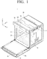
- FIG. 1 is a perspective view illustrating an oven according to an embodiment of the present disclosure.
- an oven 1 may include an outer case 10 for forming the outside of the oven, and a cooking chamber 20 for storing food therein.
- the cooking chamber 20 may be arranged inside the outer case 10, and formed in a cube shape approximately by an inner case 12 with its open front face.
- the open front face of the cooking chamber 20 may be selectively opened and closed by a door 14 which is rotatably coupled to the outer case 10.
- the door 14 may be provided with a handle 16 at its upper part so that a user can easily open the door 14.
- the door 14 may be mounted with a door glass 14A so that the user can check the condition of the cooking chamber 20 with naked eyes.
- a plurality of guide rails may be arranged on both sides of the cooking chamber 20 to use the space effectively by splitting the space of the cooking chamber 20, and a rack on which food or a food container is placed may be detachably coupled to each guiderail.
- a heater (not shown) for heating the food on the rack may be mounted on an upper surface of the cooking chamber 20.
- a circulation fan (not shown) for circulating air in the cooking chamber 20 may be mounted on a rear surface of the cooking chamber 20. The circulation fan may maintain the temperature in the cooking chamber 20 to be uniform so as to make it possible to cook quickly.
- a machine room may be provided at the upper part of the cooking chamber 20.
- the machine room may be formed between the upper part of the inner case 12 and a cover 36, and separately provided from the cooking chamber 20.
- the machine room may be provided with various types of electric parts (not shown) such as a circuit board necessary for the operation of the oven 1.
- a front surface panel 30 may be provided on the front surface of the machine room.
- the front surface panel 30 may include a display unit 32 for displaying the cooking condition of the oven 1 and the operation state of the user, and a button unit 34 for receiving a user command for controlling the operation of the oven 1.
- FIG. 2 is a perspective view illustrating an oven without a door and a cover
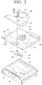
- FIG. 3 is an exploded perspective view illustrating upper configuration of an oven.
- the machine room provided outside the cooking chamber 20 may include a first duct 100 arranged outside the cooking chamber 20 and tunneled with the inside of the cooking chamber 20, a second duct 300 to which forcibly suctioned external air is transferred, a partition 200 for splitting the first and second ducts 100 and 300, and a blowing fan 500 which suctions and blows external fluid.
- a plurality of electric parts may be mounted on the upper surface of the partition 200 to perform cooking and cleaning operations of the oven 1.
- the blowing fan 500 may be arranged on a rear unit of the machine room.
- the external air of the oven 1 may be suctioned into the machine room through an external hole 11 formed on the outer case 10.
- the blowing fan 500 may cool the inside of the machine room by suctioning the external air by a centrifugal fan, and forcibly blow hot air in the machine room to the outside of the oven 1 through a main outlet 330.
- air in the cooking chamber 20 may be selectively discharged to the outside of the cooking chamber 20 through the main discharging unit 300.
- the structure for discharging the air in the cooking chamber 20 will be described in detailed with reference to the following drawings.
- the first duct 100, the partition 200, the second duct 300 may be stacked vertically on the outside of the upper part of the cooking chamber 20.
- the first duct 100 may be coupled to the bottom surface of the partition 200
- the second duct 300 may be coupled to the upper surface of the partition 200, so that a space where air flow upwardly or downwardly from the partition 220 is formed.
- the space through which air flows may be provided by a first passage part S1 (see FIG. 5 ) formed by coupling the first duct 100 and the partition 200, and a second passage part S2 (see FIG. 5 ) formed by coupling the second duct 300 and the partition 200.
- the cooking chamber 20 may be provided with a cooking chamber outlet 25 connected to the inside of the cooking chamber 20 to discharge air in the cooking chamber 20 on the upper surface of the inner case 12 that forms the cooking chamber 20.
- the cooking chamber outlet 25 may include a plurality of cooking chamber outlets.
- One end of the first duct 100 may be coupled to the partition 200 to form the first passage part S1.
- a sensor 160 may be arranged in the first passage part S1 (see FIG. 5 ).
- An exhaust pipe 120 may be formed on the other end of the first duct 100, and a first extension pipe 110 extending downwardly from the exhaust pipe 120 and tunneled with the cooking chamber outlet 25 may be formed.
- the first extension pipe 110 may be coupled to the cooking chamber outlet 25. Accordingly, air discharged from the cooking chamber 20 may be guided to the first passage part S1 through the exhaust pipe 120. It is desirable that a space between the first extension pipe 110 and the cooking chamber outlet 25 is sealed so that air in the cooking chamber 20 may flow into the first duct 100 through the exhaust pipe 120 along the first extension pipe 110.
- the sensor 160 may sense the cooking condition of the food in the cooking chamber 20 by sensing the air discharged from the inside of the cooking chamber 20, and automatically cook the food. Therefore, the sensor 160 may be disposed in the first passage part S1 to sense air heated in the cooking chamber 20. To be specific, the sensor 160 may be disposed downstream of the cooking chamber outlet 25 on an air flow path from the exhaust pipe 120 to the outlet 230 of the partition 200 along the first passage part S1.
- the first duct 100 may be part of the discharging structure for discharging air in the cooking chamber 20, and there is no need for an additional space for accommodating the sensor 160. Therefore, it is advantageous to effectively use a space with the entire oven sized being maintained.
- the sensor 160 may output cooking condition data on the food in the cooking chamber 20 to a controller (not shown) by sensing air flowing into the cooking chamber 20. According to the cooking condition sensed by the sensor 160, a heater (not shown) in the cooking chamber 20 may be ignited by a control signal of a controller to heat the food, and cooking may be completed by the control signal of the controller.
- the sensor 160 may be a vapor sensor for sensing humidity of air generated in the cooking chamber 20 during cooking, or a temperature sensor for sensing a temperature.
- the first duct 100 may be coupled to the bottom surface of the partition 200, and the second duct 300 may be coupled to the upper surface of the partition 200, which is opposite to one end.
- the blowing fan 500 may be arranged in the rear unit of the partition 200, and an inlet 210 into which external air flows and an outlet 230 which discharges air in the first duct 100 may be formed in the front unit.
- the inlet 210 may be disposed downstream of the blowing fan 500 on the air flow path from the blowing fan 50 toward the main outlet 230, and the outlet 230 may be disposed downstream of the inlet 210.
- the inlet 210 may allow part of the air forcibly flowing from the outside of the oven 1 by the blowing fan 500 and flowing through the second passage part S2 to be suctioned into the first duct 100.
- the external air passing through the inlet 210 may be guided to the first passage part S1, and discharged through the outlet 230 by passing through the sensor 160 together with air discharged from the cooking chamber 20 through the exhaust pipe 120.
- the external air passing through the inlet 210 may be mixed with the air discharged from the cooking chamber 20 (particularly, air at a cleaning mode with a higher temperature than air at a cooking mode) to reduce the temperature of the air discharged from the cooking chamber 20. Accordingly, the sensor 160 arranged in the first passage part S1 may not be exposed to high temperature air, to thereby maintain durability and prevent malfunction.
- the inlet 210 may be selectively opened and closed by an opening and closing member 365 to be described below to allow external air to be suctioned into or blocked from the first passage part S1.
- the inlet 210 may include a plurality of inlets.
- the outlet 230 may be a penetration hole where air in the first duct is discharged through the second duct 300. In other words, the outlet 230 may allow air flowing through the first passage part S1 to be discharged through the second passage part S2.
- the outlet 230 may include a plurality of outlets.
- One end of the second duct 300 may be engaged with the partition 200 to form the second passage part S2.
- One side of the second duct 300 may be formed in a round shape to surround the outer surface of the blowing fan 500, and include a main inlet 310 through which external air is forcibly suctioned on its upper part, and the main outlet 330 through which air in the first duct 100 and the second duct 300 is discharged on the other side, which is opposite to one side.
- the main inlet 310 may be formed to have a circular cross-section toward the upper surface of the second duct 300 where the blowing fan 500 is disposed so that external air may be suctioned by the blowing fan 500.
- the main outlet 330 may be formed to have a rectangular cross-section toward the side surface of the second duct 300.
- the blowing fan 500 may rotate between the second duct 300 and the partition 200 since a rotational shift is fixed to the partition 200.
- the second duct 300 may surround the blowing fan 500 to fix a mounting position of the blowing fan 500, and at the same time, guide to discharge the air flowing from the blowing fan 500 to the outside of the oven 1 through the main outlet 330 smoothly.
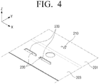
- FIG. 4 is an enlarged perspective view of part IV shown in FIG. 3 .
- the partition 200 may include a first inclined surface 201 where a portion including the inlet 210 is inclined downwardly toward one side, and a first flat surface 203 where a portion including the outlet 230 is formed flat.
- the amount of air flowing into the inlet 210 may be smaller than the amount of air discharged through the outlet 230. Since the amount of air discharged through the outlet 230 is maintained to a certain amount, if the amount of air flowing into the inlet is greater than the amount of air discharged through the outlet 230, air which is not discharged may be prevented from flowing into the cooking chamber 20 and flowing backward.
- the amount of air flowing into the inlet 210 may be controlled according to the size of the inlet 210, and the space between the second duct 300 and the partition 200 at the position of the inlet 210.
- the area of the inlet 210 may be smaller than the area of the outlet 230.
- the outlet 230 may be disposed downstream of the sensor 160 on an air flow path along the first passage part S1.
- air in the cooking chamber 20 may flow into the first passage part S1, and pass through the sensor 160 to be discharged through the outlet 230.
- air flowing from the second passage part S2 into the first passage part S1 through the inlet 210 may be discharged to the outlet 230 through the sensor 160 together with the air flowing from the inside of the cooking chamber 20 into the first passage part S1.
- the outlet 230 may include a guide member 233 obliquely formed in the direction of the main outlet 330.
- the guide member 233 may guide the air discharged through the outlet 230 to the main outlet 330.
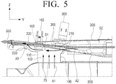
- FIG. 5 is a cross-sectional view taken along line V - V shown in FIG. 2
- FIG. 6 is an enlarged cross-sectional view of a first duct to explain air flow in an oven according to an embodiment of the present disclosure.
- the first passage part S1 tunneled with the cooking chamber, and the second passage part S2 detached from the first passage part S1 and through which forcibly suctioned external air is transferred may be disposed outside the cooking chamber 20.
- the first passage part S1 and the second passage part S2 may be tunneled with each other by the inlet 210 and the outlet 230.
- the sensor 160 may be disposed in the first passage part S1.
- the first passage part S1 may include first, second and third flow paths A1, A2 and A3. Air discharged from the cooking chamber may flow through the first flow path A1, and one end of the first flow path A1 may be tunneled with the cooking chamber outlet 25. Air flowing from the outside may flow through the second flow path A2 and one end of the second flow path A2 may be tunneled with the inlet 210. One end of the third flow path A3 may be tunneled with the outlet 230, and air of the first flow path A1 and the second flow path A2 may pass through the sensor 160 and flow through together in the third flow path A3.
- the inlet 210 When the inlet 210 is closed, only the air of the first flow path A1 may flow through the third flow path A3, and when the inlet 210 is opened, air of the first flow path A1 and the second flow path A2 may be mixed and flow through together.
- the air flowing through the third flow path A3 may be discharged from the first passage part S1 to the second passage part S2 through the outlet 230.
- Part of the air flowing into the second passage part S2 by the blowing fan 500 may flow into the second flow path A2 through the inlet 210.
- Air flowing into the second flow path A2 and air discharged to the first flow path A1 may flow through the third flow path A3 by pressure drop generated by air flow.
- the mixed air flowing through the third flow path A3 may be discharged to the second passage part S2 through the outlet 230, and discharged to the outside of the oven 1 through the main outlet 330.
- the sensor 160 is arranged in the first passage part S1, to be specific, is arranged downstream of the exhaust pipe 120 that discharges air in the cooking chamber 20 or the inlet 210 on the air flow path along the first passage part S1.
- the air flowing through the first flow path A1 and the air flowing through the second flow path A2 may flow by passing through the sensor 160.
- the inlet 210 may be opened or closed by an opening and closing member 365.
- the opening and closing member 365 may have elasticity and be formed in a size large enough to accommodate all the inlets.
- the opening and closing member 365 may be connected to an end of an actuator 360, and driven upwardly and downwardly by the actuator 360.
- the air in the cooking chamber 20 may flow into the first flow path A1, and then to third flow path A3 by passing through the sensor 160.
- the inlet 210 When the inlet 210 is opened, the air flowing from the second passage part S2 to the second flow path A2 through the inlet 210 may be discharged to the third flow path A3 by passing through the sensor 160 together with the air flowing into the first flow path A1 from the inside of the cooking chamber 20. Since the air flowing through the second flow path S2 is mixed with the air flowing through the first flow path A1, the temperature of the air that passes through the sensor 160 may be lower than the temperature in the cooking chamber. Accordingly, the sensor 160 may be protected from direct heat by lowering the temperature of the air that flows by passing through the sensor 160.
- Both the air in the cooling chamber 20 that is discharged to the exhaust pipe 120 and the air flowing into the inlet 210 may be discharged to the second passage part S2 through the outlet 230.
- a sum of the amount of air in the cooking chamber 20 flowing into the first passage part S1 and the amount of air flowing into the inlet 210 of the air of the second passage part S2 may be the same as the amount of air discharged to the second passage part S2 through the outlet 230.
- the amount of air discharged to the second passage part S2 through the outlet 230 may be maintained to a certain amount.
- the amount of air flowing into the first passage part S1 through the inlet 210 of the air of the second passage part S2 increases, the amount of air flowing into the first passage part S1 through the exhaust pipe 120 of the air in the cooking chamber 20 may be relatively reduced.
- the amount of air flowing into the first passage part S1 through the inlet 210 of the air of the second passage part S2 is reduced, the amount of air flowing into the first passage part S1 through the exhaust pipe 120 of the fluid in the cooking chamber 20 may relatively increase.
- the inlet 210 is closed, the amount of air discharged to the second passage part S2 through the outlet 230 is the same as the amount of air in the cooking chamber that is discharged through the exhaust pipe 120.
- the amount of air flowing through the inlet 210 may be controlled by adjusting a cross-section of the inlet 210, the position of the inlet 210 in the partition 200, or the space between the partition 200 and the second duct 300.
- the amount of air discharged from the side of the cooking chamber 20 may be controlled by adjusting the amount of air flowing into the inlet 210.
- the pressure drop may occur near the outlet 230, and the air flowing through the third flow path A3 may be discharged to the second passage part S2 through the outlet 230.
- the air discharged to the outlet 230 may be discharged to the outside through the main outlet 330 together with the air flowing through the second passage part S2.
- the second passage part S2 may be formed by vertically combining the second duct 300 with the partition 200.
- the second passage part S2 may have a portion adjacent to the outlet 230 that is narrower than a portion adjacent to the inlet 210, and the cross section of the second passage part S2 may gradually decreases from the inlet 210 toward the outlet 230.
- the second passage part S2 may have a portion where a space between the second duct 300 and the partition 200 is narrowed and a portion where a space between the second duct 300 and the partition 200 is maintained to be uniform in a vertical direction.
- the height of the second passage part S2 may be reduced by at least one of a first inclined surface 201 where the inlet 210 of the partition 200 is inclined downwardly toward one side or a second inclined surface 301 where a portion of the second duct 300 corresponding to the inlet 210 is inclined upwardly toward one side.
- the height of the second passage part S2 may be kept substantially same by a first flat surface of the partition 200 and a second flat surface 303 of the second duct 300.
- the second passage part S2 may include a main inlet 301 into which external air is forcibly suctioned, and a main outlet 330 thorough which air transferred from the first and second passages parts S1 and S2 is discharged.
- the blowing fan 500 may be provided in the main inlet 301 and the air suctioned into the second passage part S2 through the main inlet 301 by the blowing fan 500 may be gradually accelerated by passing through a portion where the height of the second passage part S2 is reduced and then discharged to the outside through the main outlet 330.
- the partition 200 is penetrated to form the inlet 210 and the outlet 230.
- the inlet 210 may allow part of air flowing through the second passage part S2 to flow into the first passage part S1. When the inlet 210 is opened, air may flow into the inlet 210 and pass through the sensor 160, and the air flowing into the inlet may lower the temperature in the first passage part S1.
- the outlet 230 may allow air flowing through the first passage part S1 to be discharged to the second passage part S2.
- the outlet 230 may include a guide member 233 bent inwardly toward the second passage part S2, and the cross-section of the second passage part S2 may be narrowed and then widened at a position where the outlet 230 is disposed by the guide member 233.
- the air pressure may be low and the flowing speed may be high in the upstream of the guide member 233, which is relatively narrow, and the air pressure may be high and the flowing speed may be low in the downstream of the guide member 233, which is relatively wider. Therefore, the air of the first passage part S1 may be discharged through the outlet 230.
- the inlet 210 may be formed at a portion where the height of the second passage part S2 is reduced, and the outlet 230 may be formed at one end of a parallel unit.
- the outlet 230 may be formed at a portion where the height of the second passage part S2 is uniform to maintain the amount of air discharged to the second passage part S2 through the outlet 230 to be within a certain range. In other words, since a space between the second duct 300 and the partition 200 at a position where the outlet 230 is disposed remains uniform, the amount of air discharged through the outlet 230 may be maintained within a certain range.
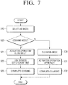
- FIG. 7 is a flowchart illustrating a controlling process of an oven according to an embodiment of the present disclosure.
- the operation of the oven 1 may be a cooking mode S20 and a cleaning mode S30.
- the food may be automatically cooked by using the sensor 160.
- pyrolytic cleaning may be performed for removing impurities such as oil sludge, stains, etc.in the cooking chamber 20 generated at the time of cooking food with high temperature heat.
- the temperature of the cooking chamber may rise above 300 °C.
- an operation mode of an oven may be selected by a user at step S10.
- the inlet 210 When a user selects the cooking mode at step S20, the inlet 210 may be closed at step S21.
- the opening and closing member 365 may be downwardly moved by the operation of the actuator 360 to close the inlet 210, and external air flowing into the inlet 210 may be blocked.
- the food may be automatically cooked by selecting a cooking time by using the sensor 160 disposed in the first passage part S1 at step S22. Only the air in the cooking chamber which is discharged through the exhaust pipe 120 may flow through the first passage part S1 by closing the inlet 210. Accordingly, the sensor 160 may sense only the air from the food in the cooking chamber 20, and provide optimal environment for determining the cooking condition of the food.
- the operation of the oven 1 When cooking is completed at step S20, the operation of the oven 1 may be completed.
- the inlet 210 may be opened at step S31.
- the opening and closing member 365 may be upwardly moved by the operation of the actuator 360 and open the inlet 210.
- the external air may flow into the first passage part S1 through the inlet 210.
- the sensor 160 may not be used at the cleaning mode S30, but the operation be performed at a high temperature at the cleaning mode S30. Therefore, the temperature of air flowing through the sensor 160 may be lowered by opening the inlet 210 to protect the sensor 160 from the high temperature air discharged from the cooking chamber 20. In other words, when cleaning is completed at step S32, the operation of the oven 1 may be completed.
- the inlet 210 may be closed so that the sensor 160 may sense the cooking condition of the food with only air discharged from the cooking chamber 20 at the cooking mode S20 where the temperature is relatively low, and the inlet 210 may be opened so that hot air in the cooking chamber 20 may not be in direct contact with the sensor but may be mixed with the air flowing through the inlet 210 to allow air at a lower temperature than a temperature of the cooking chamber to contact the sensor at the cleaning mode S30 where the temperature is relatively high, thereby protecting a heat sensitive sensor. Thus, the life of the sensor may be increased with such structure.
- the inlet 210 may be closed, and the air in the cooking chamber 20 may flow into the first duct 100, and pass through the sensor 160 to be discharged to the outlet 230.
- the inlet 210 may be opened, and air flowing from the second duct 300 into the first duct 100 through the inlet 210 and air flowing from the inside of the cooking chamber 20 into the first duct 100 may be discharged to the outlet 230 through the sensor 160.
- the oven control process according to the present disclosure may include at least one of the above-described modes, some of modes may be omitted, or other modes may be further included. Operations performed by the oven control process according to the present disclosure may be performed in a sequential, parallel, repetitive, or heuristic manner. Also, some operations may be performed in a different order, omitted, or other operations may be added.
- the sensor 160 is fixed to the first passage part S1. According to an embodiment which is not part of the invention, the sensor 160 can selectively move to the first and second passage parts S1 and S2.
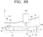
- FIGS. 8A and 8B are views illustrating an operation of a sensor provided in an oven which is not part of the invention.
- a sensor 160' may be combined with one end of an actuator 360'.
- the sensor 160' may be movably arranged to at least one of the first and second passage parts S1 and S2 by the operation of the actuator 360'.
- the inlet 210 may be opened or closed by moving the sensor 160' upwardly and downwardly.
- the sensor 160' may move into the second passage part S2 and the inlet 210 may be opened.
- the air flowing into the first duct 100 from the second duct 300 through the open inlet 210 may be discharged to the outlet 230 together with the air flowing into the first duct 100 from the inside of the cooking chamber 20.
- the sensor 160' may not be used. Thus, the sensor 160' may not need to be arranged in the first passage part S1.
- the sensor 160' may move into the first passage part S1 and close the inlet 210 at the cooking mode at step S20.
- the air in the cooking chamber 20 may flow into the first duct 100, and pass through the sensor 160' to be discharged to the outlet 230.
- the sensor 160' may be positioned in the first passage part S1 to sense the air discharged from the cooking chamber 20 at the cooking mode S20.
- the sensor 160' When the sensor 160' is variably positioned in the first passage part S1 or the second passage part S2, the sensor 160' may be exposed to the air in the cooking chamber 20 only at the cooking mode S20 that uses the sensor 160', and may not be exposed at the cleansing mode S30.
- the sensor 160' disposed in the second passage part S2 at the cleansing mode S30 may maintain durability for not being exposed to high temperature air and the malfunction of the sensor 160' may be prevented in advance.
Landscapes
- Engineering & Computer Science (AREA)
- Chemical & Material Sciences (AREA)
- Combustion & Propulsion (AREA)
- Mechanical Engineering (AREA)
- General Engineering & Computer Science (AREA)
- Chemical Kinetics & Catalysis (AREA)
- Electric Stoves And Ranges (AREA)
- Electric Ovens (AREA)
Claims (13)
- Ofen (1), der Folgendes umfasst:eine Kochkammer (20);einen ersten Durchgangsteil (S1), der außerhalb der Kochkammer angeordnet und mit der Kochkammer getunnelt ist;einen Sensor (160), der in dem ersten Durchgangsteil angeordnet ist;einen zweiten Durchgangsteil (S2), der von dem ersten Durchgangsteil durch eine Partition (200) getrennt ist, und durch den zwangsweise gesaugte externe Luft transferiert wird; undeinen Einlass (210) und einen Auslass (230), die konfiguriert sind, zu ermöglichen, den ersten und zweiten Durchgangsteil miteinander zu tunneln;wobei der Einlass und der Auslass in der Partition 200 ausgebildet sind,wobei basierend darauf, dass der Einlass geschlossen ist, Luft in der Kochkammer in den ersten Durchgangsteil strömt und dann durch den Sensor hindurch geht, um durch den Auslass abgeleitet zu werden, und basierend darauf, dass der Einlass geöffnet ist, Luft, die von dem zweiten Durchgangsteil in den ersten Durchgangsteil durch den Einlass strömt, durch den Sensor hindurch geht, um durch den Auslass zusammen mit der Luft in der Kochkammer, die in den ersten Durchgangsteil strömt, abgeleitet zu werden.
- Ofen nach Anspruch 1, wobei der zweite Durchgangsteil (S2) einen Abschnitt neben dem Auslass (230) aufweist, der schmaler als ein Abschnitt neben den Einlass (210) ist.
- Ofen nach Anspruch 1, wobei sich ein Querschnitt des zweiten Durchgangsteils (S2) graduell von dem Einlass zu dem Auslass hin verringert.
- Ofen nach Anspruch 1, wobei der zweite Durchgangsteil (S2) einen Haupteinlass (301), in den externe Luft zwangsweise gesaugt wird, und einen Hauptauslass (330), durch den von dem ersten und zweiten Durchgangsteil transferierte Luft abgeleitet wird, umfasst.
- Ofen nach Anspruch 4, wobei der Haupteinlass (301) mit einem Zuluftventilator (500) montiert ist.
- Ofen nach Anspruch 1, wobei der Sensor (160) stromabwärts von einem Kochkammerauslass (25) liegt, der Luft in der Kochkammer (20) oder dem Einlass (210) auf einem Luftstrompfad entlang des ersten Durchgangsteils (S1) ableitet.
- Ofen nach Anspruch 6, wobei der Auslass (230) stromabwärts von dem Sensor (160) auf dem Luftstrompfad entlang des ersten Durchgangsteils (S1) liegt.
- Ofen nach Anspruch 1, der ferner Folgendes umfasst:
ein Öffnungs- und Schließglied (365), das konfiguriert ist, den Einlass zu öffnen und zu schließen; und
ein Betätigungsglied (360), das konfiguriert ist, das Öffnungs- und Schließglied anzutreiben. - Ofen nach Anspruch 8, wobei ein Bereich des Einlasses (210) kleiner als ein Bereich des Auslasses (230) ist.
- Ofen nach Anspruch 1, wobei der erste Durchgangsteil (S1) zwischen einem ersten Kanal (100) und der Partition ausgebildet ist und
wobei der zweite Durchgangsteil zwischen einem zweiten Kanal (300) und der Partition ausgebildet ist. - Ofen nach Anspruch 10, wobei die Partition (200) auf eine Weise ausgebildet ist, dass ein Abschnitt, der den Einlass beinhaltet, nach unten zu einer Seite geneigt ist.
- Ofen nach Anspruch 10, wobei der erste Kanal (100) außerhalb der Kochkammer angeordnet und mit der Kochkammer getunnelt ist;
wobei die Partition (200) mit dem ersten Kanal gekoppelt ist, wobei die Partition den Einlass, in den externe Luft strömt, und den Auslass (230), der Luft in dem ersten Kanal ableitet, beinhaltet; und
wobei ein zweiter Kanal (300) mit der Partition gekoppelt ist, wobei der zweite Kanal einen Haupteinlass (301), in den externe Luft zwangsweise gesaugt wird, und einen Hauptauslass (330), der interne Luft ableitet, beinhaltet,
wobei der erste Durchgangsteil (S1) zwischen dem ersten Kanal und der Partition ausgebildet ist;
wobei der zweite Durchgangsteil (S2) zwischen dem zweiten Kanal und der Partition ausgebildet ist;
wobei Luft in der Kochkammer in den ersten Kanal strömt und bei einem Kochmodus durch den Sensor hindurch geht, um durch den Auslass abgeleitet zu werden, und bei einem Reinigungsmodus durch den Sensor hindurch geht, um durch den Auslass zusammen mit Luft, die in den ersten Kanal von dem zweiten Kanal durch den Einlass strömt, abgeleitet zu werden. - Ofen nach Anspruch 12, wobei der Sensor (160) in einem Raum liegt, durch den Luft in der Kochkammer und Luft, die von dem Einlass strömt, zusammen strömen.
Applications Claiming Priority (2)
| Application Number | Priority Date | Filing Date | Title |
|---|---|---|---|
| KR1020160069696A KR102210370B1 (ko) | 2016-06-03 | 2016-06-03 | 오븐 |
| PCT/KR2017/005853 WO2017209582A1 (ko) | 2016-06-03 | 2017-06-05 | 오븐 |
Publications (3)
| Publication Number | Publication Date |
|---|---|
| EP3438552A1 EP3438552A1 (de) | 2019-02-06 |
| EP3438552A4 EP3438552A4 (de) | 2019-05-08 |
| EP3438552B1 true EP3438552B1 (de) | 2021-05-19 |
Family
ID=60478930
Family Applications (1)
| Application Number | Title | Priority Date | Filing Date |
|---|---|---|---|
| EP17807075.1A Active EP3438552B1 (de) | 2016-06-03 | 2017-06-05 | Ofen |
Country Status (4)
| Country | Link |
|---|---|
| US (1) | US11067287B2 (de) |
| EP (1) | EP3438552B1 (de) |
| KR (1) | KR102210370B1 (de) |
| WO (1) | WO2017209582A1 (de) |
Families Citing this family (5)
| Publication number | Priority date | Publication date | Assignee | Title |
|---|---|---|---|---|
| CN109059053B (zh) * | 2018-09-01 | 2023-09-29 | 福建庆和厨具设备有限公司 | 节能环保一体式炉灶及其工作方法 |
| EP3760931B1 (de) * | 2019-07-04 | 2025-06-25 | Electrolux Appliances Aktiebolag | Backofen mit ofenmuffel und kühlkanal |
| KR102809921B1 (ko) | 2020-03-31 | 2025-05-22 | 삼성전자주식회사 | 조리기기 |
| KR20230106027A (ko) * | 2022-01-05 | 2023-07-12 | 삼성전자주식회사 | 오븐 |
| KR20240018272A (ko) | 2022-08-02 | 2024-02-13 | 엘지전자 주식회사 | 조리기기 |
Family Cites Families (19)
| Publication number | Priority date | Publication date | Assignee | Title |
|---|---|---|---|---|
| US3027444A (en) * | 1960-11-16 | 1962-03-27 | Gen Electric | Hydraulic thermostat bulb shielding means |
| US3499431A (en) * | 1967-06-26 | 1970-03-10 | Glenwood Range Co | Cooking range preheat and vent systems |
| US4587393A (en) | 1984-01-05 | 1986-05-06 | Matsushita Electric Industrial Co., Ltd. | Heating apparatus having a sensor for terminating operation |
| FR2679657B1 (fr) | 1991-07-26 | 1997-06-20 | Cogia | Procede et dispositif de detection de vapeur d'eau dans un volume d'air et generateur de vapeur et four de cuisson a la vapeur utilisant ceux-ci. |
| CA2111058A1 (en) | 1993-12-09 | 1995-06-10 | Goldstar Co., Ltd. | Method for automatically controlling cooking of food with moisture content |
| KR0142501B1 (ko) | 1995-04-24 | 1998-08-17 | 배순훈 | 증기센서를 이용한 전자렌지의 자동조리 제어방법 |
| KR100186405B1 (ko) | 1996-03-18 | 1999-03-20 | 구자홍 | 가스오븐레인지의 댐퍼 구동방법 |
| KR20010108981A (ko) * | 2000-06-01 | 2001-12-08 | 구자홍 | 가스오븐레인지의 조리실 배기구조 |
| DE102004003409A1 (de) * | 2004-01-23 | 2005-08-18 | Electrolux Schwanden Ag | Multivalent nutzbares Belüftungs-/Kühlungsmodul für Gargeräte mit verschiedenen Garbetriebsarten |
| CH711637B1 (de) | 2004-07-21 | 2017-04-13 | V Zug Ag | Gargerät mit steuerbarer Entlüftung. |
| KR100786087B1 (ko) | 2006-05-06 | 2007-12-21 | 엘지전자 주식회사 | 조리기기 |
| JP2010038368A (ja) * | 2008-07-31 | 2010-02-18 | Sharp Corp | 加熱調理器 |
| KR101659019B1 (ko) | 2010-01-27 | 2016-09-23 | 엘지전자 주식회사 | 조리기기 |
| KR101474494B1 (ko) | 2010-03-02 | 2014-12-23 | 삼성전자 주식회사 | 오븐 |
| IT1402113B1 (it) | 2010-10-08 | 2013-08-28 | Giorik Spa | Forno per la cottura a vapore di alimenti |
| JP5800622B2 (ja) * | 2011-07-27 | 2015-10-28 | シャープ株式会社 | 加熱調理器 |
| KR101931366B1 (ko) | 2012-07-20 | 2018-12-21 | 삼성전자주식회사 | 오븐 |
| US20150241069A1 (en) | 2014-02-27 | 2015-08-27 | Electrolux Home Products, Inc. | Wall oven cooling system |
| JP6310820B2 (ja) * | 2014-08-29 | 2018-04-11 | シャープ株式会社 | 加熱調理器 |
-
2016
- 2016-06-03 KR KR1020160069696A patent/KR102210370B1/ko active Active
-
2017
- 2017-06-05 WO PCT/KR2017/005853 patent/WO2017209582A1/ko not_active Ceased
- 2017-06-05 EP EP17807075.1A patent/EP3438552B1/de active Active
- 2017-06-05 US US16/099,907 patent/US11067287B2/en active Active
Non-Patent Citations (1)
| Title |
|---|
| None * |
Also Published As
| Publication number | Publication date |
|---|---|
| US20190178500A1 (en) | 2019-06-13 |
| KR102210370B1 (ko) | 2021-02-01 |
| US11067287B2 (en) | 2021-07-20 |
| EP3438552A1 (de) | 2019-02-06 |
| KR20170137488A (ko) | 2017-12-13 |
| EP3438552A4 (de) | 2019-05-08 |
| WO2017209582A1 (ko) | 2017-12-07 |
Similar Documents
| Publication | Publication Date | Title |
|---|---|---|
| KR102124833B1 (ko) | 오븐 | |
| EP3438552B1 (de) | Ofen | |
| KR102153615B1 (ko) | 조리기기 | |
| EP3309463B1 (de) | Ofen | |
| KR101179729B1 (ko) | 오븐 | |
| EP1783432B1 (de) | Vorrichtung zum Kühlen eines Gargeräts | |
| EP1731843B1 (de) | Ofen | |
| US7629561B2 (en) | Electric oven with hood having opening/closing device to open and close an exhaust passage | |
| KR100628081B1 (ko) | 전기 오븐 레인지 | |
| EP2977684A1 (de) | Ofen | |
| US10371392B2 (en) | Cooking appliance | |
| US20050224068A1 (en) | Cooling apparatus of cooking appliance | |
| KR20180028856A (ko) | 도어 및 이를 갖는 오븐 | |
| KR100938206B1 (ko) | 빌트 인 조리기기 | |
| KR100717437B1 (ko) | 전기 오븐의 도어 냉각 구조 | |
| KR100676138B1 (ko) | 오븐 | |
| KR20070059394A (ko) | 전기 오븐 | |
| KR100678665B1 (ko) | 오븐 | |
| KR102683542B1 (ko) | 오븐 | |
| KR100819593B1 (ko) | 조리기기 | |
| KR100678666B1 (ko) | 오븐렌지의 도어 냉각장치 | |
| KR100735973B1 (ko) | 조리기기 | |
| KR100657929B1 (ko) | 가스오븐레인지의 냉각구조 | |
| KR20090063421A (ko) | 빌트 인 조리기기 | |
| KR20000008059U (ko) | 가스조리기의 탑케이스 데코레이션부 냉각구조 |
Legal Events
| Date | Code | Title | Description |
|---|---|---|---|
| STAA | Information on the status of an ep patent application or granted ep patent |
Free format text: STATUS: THE INTERNATIONAL PUBLICATION HAS BEEN MADE |
|
| PUAI | Public reference made under article 153(3) epc to a published international application that has entered the european phase |
Free format text: ORIGINAL CODE: 0009012 |
|
| STAA | Information on the status of an ep patent application or granted ep patent |
Free format text: STATUS: REQUEST FOR EXAMINATION WAS MADE |
|
| 17P | Request for examination filed |
Effective date: 20181031 |
|
| AK | Designated contracting states |
Kind code of ref document: A1 Designated state(s): AL AT BE BG CH CY CZ DE DK EE ES FI FR GB GR HR HU IE IS IT LI LT LU LV MC MK MT NL NO PL PT RO RS SE SI SK SM TR |
|
| AX | Request for extension of the european patent |
Extension state: BA ME |
|
| A4 | Supplementary search report drawn up and despatched |
Effective date: 20190410 |
|
| RIC1 | Information provided on ipc code assigned before grant |
Ipc: F24C 15/20 20060101AFI20190404BHEP Ipc: F24C 7/08 20060101ALI20190404BHEP Ipc: F24C 15/00 20060101ALI20190404BHEP Ipc: F24C 14/02 20060101ALI20190404BHEP |
|
| DAV | Request for validation of the european patent (deleted) | ||
| DAX | Request for extension of the european patent (deleted) | ||
| GRAP | Despatch of communication of intention to grant a patent |
Free format text: ORIGINAL CODE: EPIDOSNIGR1 |
|
| STAA | Information on the status of an ep patent application or granted ep patent |
Free format text: STATUS: GRANT OF PATENT IS INTENDED |
|
| INTG | Intention to grant announced |
Effective date: 20201201 |
|
| GRAS | Grant fee paid |
Free format text: ORIGINAL CODE: EPIDOSNIGR3 |
|
| GRAA | (expected) grant |
Free format text: ORIGINAL CODE: 0009210 |
|
| STAA | Information on the status of an ep patent application or granted ep patent |
Free format text: STATUS: THE PATENT HAS BEEN GRANTED |
|
| AK | Designated contracting states |
Kind code of ref document: B1 Designated state(s): AL AT BE BG CH CY CZ DE DK EE ES FI FR GB GR HR HU IE IS IT LI LT LU LV MC MK MT NL NO PL PT RO RS SE SI SK SM TR |
|
| REG | Reference to a national code |
Ref country code: GB Ref legal event code: FG4D |
|
| REG | Reference to a national code |
Ref country code: CH Ref legal event code: EP |
|
| REG | Reference to a national code |
Ref country code: DE Ref legal event code: R096 Ref document number: 602017038922 Country of ref document: DE |
|
| REG | Reference to a national code |
Ref country code: AT Ref legal event code: REF Ref document number: 1394338 Country of ref document: AT Kind code of ref document: T Effective date: 20210615 |
|
| REG | Reference to a national code |
Ref country code: IE Ref legal event code: FG4D |
|
| REG | Reference to a national code |
Ref country code: LT Ref legal event code: MG9D |
|
| REG | Reference to a national code |
Ref country code: AT Ref legal event code: MK05 Ref document number: 1394338 Country of ref document: AT Kind code of ref document: T Effective date: 20210519 |
|
| REG | Reference to a national code |
Ref country code: NL Ref legal event code: MP Effective date: 20210519 |
|
| PG25 | Lapsed in a contracting state [announced via postgrant information from national office to epo] |
Ref country code: HR Free format text: LAPSE BECAUSE OF FAILURE TO SUBMIT A TRANSLATION OF THE DESCRIPTION OR TO PAY THE FEE WITHIN THE PRESCRIBED TIME-LIMIT Effective date: 20210519 Ref country code: AT Free format text: LAPSE BECAUSE OF FAILURE TO SUBMIT A TRANSLATION OF THE DESCRIPTION OR TO PAY THE FEE WITHIN THE PRESCRIBED TIME-LIMIT Effective date: 20210519 Ref country code: BG Free format text: LAPSE BECAUSE OF FAILURE TO SUBMIT A TRANSLATION OF THE DESCRIPTION OR TO PAY THE FEE WITHIN THE PRESCRIBED TIME-LIMIT Effective date: 20210819 Ref country code: FI Free format text: LAPSE BECAUSE OF FAILURE TO SUBMIT A TRANSLATION OF THE DESCRIPTION OR TO PAY THE FEE WITHIN THE PRESCRIBED TIME-LIMIT Effective date: 20210519 Ref country code: LT Free format text: LAPSE BECAUSE OF FAILURE TO SUBMIT A TRANSLATION OF THE DESCRIPTION OR TO PAY THE FEE WITHIN THE PRESCRIBED TIME-LIMIT Effective date: 20210519 |
|
| PG25 | Lapsed in a contracting state [announced via postgrant information from national office to epo] |
Ref country code: GR Free format text: LAPSE BECAUSE OF FAILURE TO SUBMIT A TRANSLATION OF THE DESCRIPTION OR TO PAY THE FEE WITHIN THE PRESCRIBED TIME-LIMIT Effective date: 20210820 Ref country code: IS Free format text: LAPSE BECAUSE OF FAILURE TO SUBMIT A TRANSLATION OF THE DESCRIPTION OR TO PAY THE FEE WITHIN THE PRESCRIBED TIME-LIMIT Effective date: 20210919 Ref country code: LV Free format text: LAPSE BECAUSE OF FAILURE TO SUBMIT A TRANSLATION OF THE DESCRIPTION OR TO PAY THE FEE WITHIN THE PRESCRIBED TIME-LIMIT Effective date: 20210519 Ref country code: PT Free format text: LAPSE BECAUSE OF FAILURE TO SUBMIT A TRANSLATION OF THE DESCRIPTION OR TO PAY THE FEE WITHIN THE PRESCRIBED TIME-LIMIT Effective date: 20210920 Ref country code: NO Free format text: LAPSE BECAUSE OF FAILURE TO SUBMIT A TRANSLATION OF THE DESCRIPTION OR TO PAY THE FEE WITHIN THE PRESCRIBED TIME-LIMIT Effective date: 20210819 Ref country code: PL Free format text: LAPSE BECAUSE OF FAILURE TO SUBMIT A TRANSLATION OF THE DESCRIPTION OR TO PAY THE FEE WITHIN THE PRESCRIBED TIME-LIMIT Effective date: 20210519 Ref country code: SE Free format text: LAPSE BECAUSE OF FAILURE TO SUBMIT A TRANSLATION OF THE DESCRIPTION OR TO PAY THE FEE WITHIN THE PRESCRIBED TIME-LIMIT Effective date: 20210519 Ref country code: RS Free format text: LAPSE BECAUSE OF FAILURE TO SUBMIT A TRANSLATION OF THE DESCRIPTION OR TO PAY THE FEE WITHIN THE PRESCRIBED TIME-LIMIT Effective date: 20210519 |
|
| PG25 | Lapsed in a contracting state [announced via postgrant information from national office to epo] |
Ref country code: NL Free format text: LAPSE BECAUSE OF FAILURE TO SUBMIT A TRANSLATION OF THE DESCRIPTION OR TO PAY THE FEE WITHIN THE PRESCRIBED TIME-LIMIT Effective date: 20210519 |
|
| PG25 | Lapsed in a contracting state [announced via postgrant information from national office to epo] |
Ref country code: SK Free format text: LAPSE BECAUSE OF FAILURE TO SUBMIT A TRANSLATION OF THE DESCRIPTION OR TO PAY THE FEE WITHIN THE PRESCRIBED TIME-LIMIT Effective date: 20210519 Ref country code: SM Free format text: LAPSE BECAUSE OF FAILURE TO SUBMIT A TRANSLATION OF THE DESCRIPTION OR TO PAY THE FEE WITHIN THE PRESCRIBED TIME-LIMIT Effective date: 20210519 Ref country code: ES Free format text: LAPSE BECAUSE OF FAILURE TO SUBMIT A TRANSLATION OF THE DESCRIPTION OR TO PAY THE FEE WITHIN THE PRESCRIBED TIME-LIMIT Effective date: 20210519 Ref country code: RO Free format text: LAPSE BECAUSE OF FAILURE TO SUBMIT A TRANSLATION OF THE DESCRIPTION OR TO PAY THE FEE WITHIN THE PRESCRIBED TIME-LIMIT Effective date: 20210519 Ref country code: CZ Free format text: LAPSE BECAUSE OF FAILURE TO SUBMIT A TRANSLATION OF THE DESCRIPTION OR TO PAY THE FEE WITHIN THE PRESCRIBED TIME-LIMIT Effective date: 20210519 Ref country code: EE Free format text: LAPSE BECAUSE OF FAILURE TO SUBMIT A TRANSLATION OF THE DESCRIPTION OR TO PAY THE FEE WITHIN THE PRESCRIBED TIME-LIMIT Effective date: 20210519 Ref country code: DK Free format text: LAPSE BECAUSE OF FAILURE TO SUBMIT A TRANSLATION OF THE DESCRIPTION OR TO PAY THE FEE WITHIN THE PRESCRIBED TIME-LIMIT Effective date: 20210519 |
|
| REG | Reference to a national code |
Ref country code: CH Ref legal event code: PL |
|
| REG | Reference to a national code |
Ref country code: DE Ref legal event code: R097 Ref document number: 602017038922 Country of ref document: DE |
|
| REG | Reference to a national code |
Ref country code: BE Ref legal event code: MM Effective date: 20210630 |
|
| PLBE | No opposition filed within time limit |
Free format text: ORIGINAL CODE: 0009261 |
|
| STAA | Information on the status of an ep patent application or granted ep patent |
Free format text: STATUS: NO OPPOSITION FILED WITHIN TIME LIMIT |
|
| PG25 | Lapsed in a contracting state [announced via postgrant information from national office to epo] |
Ref country code: MC Free format text: LAPSE BECAUSE OF FAILURE TO SUBMIT A TRANSLATION OF THE DESCRIPTION OR TO PAY THE FEE WITHIN THE PRESCRIBED TIME-LIMIT Effective date: 20210519 Ref country code: LU Free format text: LAPSE BECAUSE OF NON-PAYMENT OF DUE FEES Effective date: 20210605 |
|
| 26N | No opposition filed |
Effective date: 20220222 |
|
| GBPC | Gb: european patent ceased through non-payment of renewal fee |
Effective date: 20210819 |
|
| PG25 | Lapsed in a contracting state [announced via postgrant information from national office to epo] |
Ref country code: LI Free format text: LAPSE BECAUSE OF NON-PAYMENT OF DUE FEES Effective date: 20210630 Ref country code: IE Free format text: LAPSE BECAUSE OF NON-PAYMENT OF DUE FEES Effective date: 20210605 Ref country code: CH Free format text: LAPSE BECAUSE OF NON-PAYMENT OF DUE FEES Effective date: 20210630 |
|
| PG25 | Lapsed in a contracting state [announced via postgrant information from national office to epo] |
Ref country code: IS Free format text: LAPSE BECAUSE OF FAILURE TO SUBMIT A TRANSLATION OF THE DESCRIPTION OR TO PAY THE FEE WITHIN THE PRESCRIBED TIME-LIMIT Effective date: 20210919 Ref country code: FR Free format text: LAPSE BECAUSE OF NON-PAYMENT OF DUE FEES Effective date: 20210719 Ref country code: AL Free format text: LAPSE BECAUSE OF FAILURE TO SUBMIT A TRANSLATION OF THE DESCRIPTION OR TO PAY THE FEE WITHIN THE PRESCRIBED TIME-LIMIT Effective date: 20210519 |
|
| PG25 | Lapsed in a contracting state [announced via postgrant information from national office to epo] |
Ref country code: IT Free format text: LAPSE BECAUSE OF FAILURE TO SUBMIT A TRANSLATION OF THE DESCRIPTION OR TO PAY THE FEE WITHIN THE PRESCRIBED TIME-LIMIT Effective date: 20210519 Ref country code: GB Free format text: LAPSE BECAUSE OF NON-PAYMENT OF DUE FEES Effective date: 20210819 Ref country code: BE Free format text: LAPSE BECAUSE OF NON-PAYMENT OF DUE FEES Effective date: 20210630 |
|
| PG25 | Lapsed in a contracting state [announced via postgrant information from national office to epo] |
Ref country code: CY Free format text: LAPSE BECAUSE OF FAILURE TO SUBMIT A TRANSLATION OF THE DESCRIPTION OR TO PAY THE FEE WITHIN THE PRESCRIBED TIME-LIMIT Effective date: 20210519 |
|
| PG25 | Lapsed in a contracting state [announced via postgrant information from national office to epo] |
Ref country code: HU Free format text: LAPSE BECAUSE OF FAILURE TO SUBMIT A TRANSLATION OF THE DESCRIPTION OR TO PAY THE FEE WITHIN THE PRESCRIBED TIME-LIMIT; INVALID AB INITIO Effective date: 20170605 |
|
| PG25 | Lapsed in a contracting state [announced via postgrant information from national office to epo] |
Ref country code: MK Free format text: LAPSE BECAUSE OF FAILURE TO SUBMIT A TRANSLATION OF THE DESCRIPTION OR TO PAY THE FEE WITHIN THE PRESCRIBED TIME-LIMIT Effective date: 20210519 |
|
| PG25 | Lapsed in a contracting state [announced via postgrant information from national office to epo] |
Ref country code: TR Free format text: LAPSE BECAUSE OF FAILURE TO SUBMIT A TRANSLATION OF THE DESCRIPTION OR TO PAY THE FEE WITHIN THE PRESCRIBED TIME-LIMIT Effective date: 20210519 |
|
| PG25 | Lapsed in a contracting state [announced via postgrant information from national office to epo] |
Ref country code: MT Free format text: LAPSE BECAUSE OF FAILURE TO SUBMIT A TRANSLATION OF THE DESCRIPTION OR TO PAY THE FEE WITHIN THE PRESCRIBED TIME-LIMIT Effective date: 20210519 |
|
| PGFP | Annual fee paid to national office [announced via postgrant information from national office to epo] |
Ref country code: DE Payment date: 20250520 Year of fee payment: 9 |