EP3437814B1 - Perforatrice à papier - Google Patents
Perforatrice à papier Download PDFInfo
- Publication number
- EP3437814B1 EP3437814B1 EP18173091.2A EP18173091A EP3437814B1 EP 3437814 B1 EP3437814 B1 EP 3437814B1 EP 18173091 A EP18173091 A EP 18173091A EP 3437814 B1 EP3437814 B1 EP 3437814B1
- Authority
- EP
- European Patent Office
- Prior art keywords
- paper punch
- punch according
- pressure
- fastening
- side cheeks
- Prior art date
- Legal status (The legal status is an assumption and is not a legal conclusion. Google has not performed a legal analysis and makes no representation as to the accuracy of the status listed.)
- Active
Links
Images




Classifications
-
- B—PERFORMING OPERATIONS; TRANSPORTING
- B26—HAND CUTTING TOOLS; CUTTING; SEVERING
- B26F—PERFORATING; PUNCHING; CUTTING-OUT; STAMPING-OUT; SEVERING BY MEANS OTHER THAN CUTTING
- B26F1/00—Perforating; Punching; Cutting-out; Stamping-out; Apparatus therefor
- B26F1/32—Hand-held perforating or punching apparatus, e.g. awls
- B26F1/36—Punching or perforating pliers
-
- B—PERFORMING OPERATIONS; TRANSPORTING
- B26—HAND CUTTING TOOLS; CUTTING; SEVERING
- B26D—CUTTING; DETAILS COMMON TO MACHINES FOR PERFORATING, PUNCHING, CUTTING-OUT, STAMPING-OUT OR SEVERING
- B26D5/00—Arrangements for operating and controlling machines or devices for cutting, cutting-out, stamping-out, punching, perforating, or severing by means other than cutting
- B26D5/08—Means for actuating the cutting member to effect the cut
- B26D5/10—Hand or foot actuated means
Definitions
- the invention relates to a paper punch according to the preamble of claim 1.
- a paper punch is known from the laid-open specification DE 10 2011 015 473 A1 .
- Paper punches of the type mentioned at the beginning are sold, for example, by the applicant under the designation "LEITZ 5008" and “LEITZ 5180" and have proven to be outstanding in practice due to their reliability.
- This paper punch has a pressure lever with a cover part made of sheet metal, which is pivotably mounted on lateral bearing blocks of the lower part.
- the pressure lever also has two pressure bolts, each of which acts on a punch and, when the pressure lever is depressed, pushes it down against the force of a spring in order to punch a hole in sheet material resting on a support surface on the lower part.
- the pressure bolts are each passed through a side cheek of the cover part and thickened at one end so that they engage behind the outside of the side cheek.
- a swivel rod through which the swivel axis runs, around which the pressure lever can be swiveled relative to the lower part is passed through both the bearing blocks and the side cheeks and thickened at their ends so that it too engages behind the side cheeks on their outside and not is movable.
- This fastening of the pressure bolts and the swivel rod is very stable, but is often felt to be disadvantageous from a design point of view.
- the invention is based on the idea of creating a paper punch with a more appealing design in that the outer sides of the cover part facing the user have a surface that is as smooth as possible and with a uniform color.
- the pivotable attachment of the pressure lever to the lower part takes place in that a pivot axis about which the pressure lever is pivotable relative to the lower part runs through at least one connecting element which is passed through the lower part and attached to the inside of the side cheeks.
- the at least one connecting element is only attached to the inner sides of the side cheeks and is hardly visible to the user.
- pivot pins through which the pivot axis runs, and each of which is rotatably mounted in one of the bearing blocks and firmly connected to the inside of the associated side cheek, are particularly suitable as connecting elements.
- the pivot pins it is possible for the pivot pins to be welded to the inside of the side cheeks, again preferably by means of a butt welding process.
- the pivot pins expediently each engage in a hole in the associated bearing block, from which an insertion channel, which is open to a rear region of the lower part, extends.
- the pivot pins are then first welded to the side walls.
- the side cheeks are then bent apart a little and the pivot pins are inserted into the holes in the bearing blocks.
- the insertion channels thus have the effect that the holes have a smaller depth towards the rear area, i.e. where they are used of the paper punch only small forces act from the pivot pin on the bearing blocks.
- the pivot axis can run through a telescopic pivot rod which is rotatably mounted in both bearing blocks and is pressed against the inner sides of the side cheeks by the force of a compression spring accommodated in it.
- the length of the pivot rod can expediently be reduced against the force of the compression spring to such an extent that it can be inserted between the bearing blocks.
- the paper punch can also advantageously be provided with a locking device.
- This has a first slider part slidably guided on the pivot rod, a second slider part rigidly connected to it and slidably guided on a guide rod arranged in the lower part, and a locking part, and is between a locking position in which the locking part rests against one of the fastening tongues and its movement inhibits, and a release position in which the locking part releases the fastening tongue.
- the pressure lever can then be fixed in its depressed position in which the paper punch assumes its smallest possible size, which is advantageous, for example, for packaging purposes.
- the paper punch expediently has two pressure bolts for acting on one of the punching tools, the pressure bolts each being fastened with a first end to a fastening tongue that is at a distance from one of the side cheeks from the cover part. It is provided that the first end of the pressure bolts are each fastened to the fastening tongue.
- the second end of the fastening bolt is also not visible from the outside, since it is on the relevant side cheek on the other side cheek facing inside is attached. It is therefore not necessary to pass the pressure bolt through the side cheek to form a widened head on the outside of the side cheek, so that the pressure bolts are arranged completely inside the cover part between the side cheeks and are practically invisible to the user.
- the cover part is made of sheet metal, in particular the fastening tongues can be integrally formed on the cover part.
- the cover part and the fastening tongues can be produced together from a piece of sheet metal by means of a forming process, for example by punching and subsequent embossing or bending.
- the pressure bolts, which are also made of metal, can then advantageously be welded to the inner sides of the side cheeks, a butt welding process preferably being used.
- the pressure bolts are expediently passed through a hole in the respective fastening tongue. This represents a particularly simple way of achieving power transmission from the fastening tongue to the pressure bolt.
- welding the pressure bolts to the side cheeks by means of butt welding gives unsatisfactory results when a large part of the welding current flows away via the fastening tongue.
- the holes each have a larger diameter than the thrust bolt passed through, so that when the thrust bolt is welded to the relevant side cheek, the thrust bolt can be kept at a distance from the edges of the hole and no welding current flows away through the fastening tongue.
- a sleeve receiving the first end of the relevant pressure bolt is expediently passed through the holes and has a head engaging behind the relevant fastening tongue on the side facing the other fastening tongue.
- the sleeves can advantageously each be firmly connected to the associated pressure bolt and / or to the associated fastening tongue. This opens up the possibility of first welding the pressure bolt to the associated side cheek, whereby it does not come into contact with the fastening tongue during the welding process is.
- the sleeve is then passed through the hole and engages around the fastening bolt.
- the sleeve fills the gap between the pressure bolt and the fastening tongue and creates a stable connection between the pressure bolt and the fastening tongue.
- the head prevents the sleeve from slipping through the hole.
- the connection between the sleeve and the pressure bolt and / or the sheet metal tongue can be made by pressing, welding or gluing.
- the paper punch 10 shown has a lower part 12 which is provided in a front region 14 with a support surface 16 for sheet material to be punched. On its underside, the lower part 12 has a cuttings trough 18 for receiving punched-out paper cuttings, which extends from the front area 14 to a gripping cutout 19 in a rear area 20 of the lower part 12.
- the lower part 12 has two lateral bearing blocks 22 which are arranged at a distance from one another and to which a pressure lever 24 is pivotably articulated.
- the pressure lever 24 has a cover part 26 made of sheet metal, which hinges the bearing blocks 22 on their outer sides encompassing side cheeks 28 as well as a free end piece projecting obliquely upward in the direction of the rear region 20 is.
- the pressure lever 24 has a cover part 26 made of sheet metal, which has the bearing blocks 22 on their outer sides encompassing side cheeks 28 as well as a free end 30 protruding obliquely upward in the direction of the rear area 20, on which a user can grip the pressure lever when punching 24 push down.
- the pressure lever 24 also has two pressure bolts 32 made of metal, which each rest on a punching tool, in the present exemplary embodiment a punch 33, which is slidably guided in the lower part 12, and when the free end 30 is depressed, the punch 33 concerned against the force of a spring designed as a compression spring 34 press down to pierce the sheet material resting on the support surface 16.
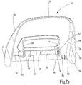
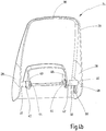
- the pressure pins 32 are, as in Figure 2b shown in detail, each with its first end 36 received through a hole 38 in a fastening tongue 40 which is integrally formed on the cover part 26 at a distance from the associated side cheek 28 and protrudes from this.
- the diameter of the holes 38 in the fastening tongues 40 is greater than the diameter of the pressure bolts 32.
- the first ends 36 of the pressure bolts 32 are therefore each received by a sleeve 42 made of metal, which is precisely inserted into the hole 38 of the fastening tongue 40 in question and has a head 44 engaging behind the fastening tongue 40 on its side facing the other fastening tongue 40.
- each of the pressure bolts 32 is welded to an inner side 48 of the associated side cheek 28, which faces the respective other side cheek 28.
- the side cheeks 28 are each provided with a recess 50 on their inner sides 48, into which a mandrel 52 engages at the second end 46 of the relevant pressure bolt 32 before the start of the welding process, which forms excess material that is melted during welding and becomes with it the associated side wall 28 connects.
- the pressure bolts 32 are also connected to their sleeves 42, which in turn are firmly connected to the associated fastening tongue 40. Welding processes can also be used for this fastening, but also gluing or pressing.
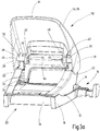
- the paper punch 10 For pivotable articulation of the pressure lever 24 on the lower part 12, the paper punch 10 according to the first embodiment has two pivot pins 54 made of metal, which are each rotatably mounted in a hole 56 in one of the bearing blocks 22, and through which the pivot axis runs around which the pressure lever 24 relative to the lower part 12 is pivotable.
- Each of the pivot pins 54 is welded to the inside 48 of one of the side walls 28.
- a further recess 58 is arranged in the inner sides 48, in which an excess of material engages in the form of a further mandrel 60 on the pivot pin 54, which is melted during welding and connected to the side cheek 28.
- An insertion channel 62 which is open to the rear area 20, extends from each of the holes 56 in the bearing blocks 22 in the direction of the rear area 20, via which the pivot pins 54 are inserted into the holes 56 during the assembly of the paper punch 10.
- the cover part 26 is bent apart a little in the area of the side cheeks 28 and elastically deformed until the pivot pins 54 can be pushed into the insertion channels 62.
- the pressure lever 24 is then advanced until the pivot pins 54 can engage in the holes 56 in the bearing blocks 22.
- the pivot pin 54 engages in the holes 56 by an elastic restoring force which acts on the side cheeks 28, or by bending the side cheeks 28 back.
- the paper punch 110 according to the second embodiment corresponds in most of the components to the paper punch 10 according to the first embodiment.
- the same features are therefore provided with the same reference symbols and are largely not described in detail below.
- the pivot axis about which the pressure lever 24 is pivotable relative to the lower part 12 does not run through two pivot pins 54, but through a pivot rod 64.
- the pivot rod 64 runs through the holes 56 in the bearing blocks 22 and lies with their ends on the inner sides 28 of the side walls 28.
- the ends of the pivot rod 64 are in circular receiving rims 66 received on the side cheeks 28 with an exact fit so that they cannot slip in the radial direction.
- the pivot rod 64 is constructed in several parts and is telescopic. As shown in particular from the exploded view in FIG Figure 4a is shown, a first part 68 and a second part 70 engaging in the first part 68 and slidably guided therein.
- the length of the swivel rod 64 can be reduced by moving the two parts 68, 70 against one another against the restoring force of a compression spring 72 accommodated in the first part 68.
- the pivot rod 64 is first passed through the holes 56 in the bearing blocks 22. Subsequently, their length is reduced by compression against the restoring force of the compression spring 72, so that the pressure lever 24 can be placed on the lower part 12, the side cheeks 28 engaging around the bearing blocks 22. Finally, the pivot rod 64 is released, so that the force of the compression spring 72 presses its two parts 68, 72 against the inner sides 48 of the side cheeks 28, their ends being received in the receiving edges 66.
- the invention relates to a paper punch 10, 110 with a lower part 12 and with a pressure lever 24, which is pivotably mounted on lateral bearing blocks 22 of the lower part 12 and which is mounted on punching tools 33, which is mounted displaceably on the lower part 12, in each case against the restoring force of a spring 34, whereby the pressure lever 24 has a cover part 26, which is pivotably connected to the bearing blocks 22 on downwardly projecting side cheeks 28, and two pressure bolts 32 for acting on one of the punching tools 33, and the pressure bolts 32 each with a first end 36 at a distance from one of the side cheeks 28 from the cover part 26 downwardly standing fastening tongue 40 are attached.
- the pressure bolts 32 are each fastened with a second end 46 to the relevant side cheek 28 on the inner side 48 thereof facing the respective other side cheek 28.
Landscapes
- Life Sciences & Earth Sciences (AREA)
- Forests & Forestry (AREA)
- Engineering & Computer Science (AREA)
- Mechanical Engineering (AREA)
- Perforating, Stamping-Out Or Severing By Means Other Than Cutting (AREA)
Claims (14)
- Perforatrice à papier comportant une partie inférieure (12) et un levier de pression (24) monté pivotant sur des supports latéraux (22) de la partie inférieure (12), et agissant sur des outils perforateurs (33) montés à coulissement sur la partie inférieure (12) respectivement à l'encontre de la force de rappel d'un ressort (34), dans laquelle le levier de pression (24) comprend une partie de recouvrement (26) reliée de manière pivotante aux supports (22) au niveau de joues latérales (28) tournées vers le bas, laquelle partie de recouvrement, par ses joues latérales (28), vient en prise autour des supports (22) au niveau de leurs côtés extérieurs opposés l'un à l'autre, caractérisée en ce que le levier de pression (24) peut être pivoté par rapport à la partie inférieure (12) autour d'un axe de pivotement qui s'étend à travers au moins un élément de liaison (54, 64) qui est guidé à travers la partie inférieure (12) et est fixé aux côtés intérieurs (48) des joues latérales (28) .
- Perforatrice à papier selon la revendication 1, caractérisée en ce que l'axe de pivotement s'étend à travers deux pivots (54), parmi lesquels chacun est monté rotatif dans l'un des supports (22) et est relié solidement au côté intérieur (48) de la joue latérale associée (28).
- Perforatrice à papier selon la revendication 2, caractérisée en ce que les pivots (54) sont soudés sur les côtés intérieurs (48) des joues latérales (28), de préférence par soudage bout à bout.
- Perforatrice à papier selon la revendication 2 ou 3, caractérisée en ce que les pivots (54) viennent en prise respectivement dans un trou (56) dans le support associé (22), trou à partir duquel s'étend un canal d'introduction (62) ouvert vers une région arrière (20) de la partie inférieure (12).
- Perforatrice à papier selon la revendication 1, caractérisée en ce que l'axe de pivotement s'étend à travers une tige de pivotement télescopique (64) qui est montée rotative dans les deux supports (22) et, par la force d'un ressort de compression (72) logé dans celle-ci, est pressée contre le côté intérieur (48) des joues latérales (28).
- Perforatrice à papier selon la revendication 5, caractérisée par un dispositif d'arrêt qui comprend une première partie coulissante guidée de manière mobile sur la tige de pivotement (64), une deuxième partie coulissante reliée rigidement à cette première partie coulissante et guidée de manière mobile sur une tige de guidage disposée dans la partie inférieure (12), et une partie d'arrêt, le dispositif d'arrêt étant mobile entre une position d'arrêt dans laquelle la partie d'arrêt s'appuie contre l'une des languettes de fixation (40) et entrave son déplacement et une position de libération dans laquelle la partie d'arrêt libère la languette de fixation (40).
- Perforatrice à papier selon l'une des revendications précédentes, caractérisée en ce que le levier de pression (24) comprend deux tiges de pression (32) pour la sollicitation respectivement de l'un des outils perforateurs (33), les tiges de pression (32) étant fixées respectivement par une première extrémité (36) à une languette de fixation (40) tournée vers le bas à partir de la partie de recouvrement (26) à distance de l'une des joues latérales (28), et les tiges de pression (32) étant fixées respectivement par une deuxième extrémité (46) à la joue latérale concernée (28) au niveau de son côté intérieur (48) tourné respectivement vers l'autre joue latérale (28).
- Perforatrice à papier selon l'une des revendications précédentes, caractérisée en ce que la partie de recouvrement (26) est fabriquée à partir de tôle.
- Perforatrice à papier selon la revendication 7 et selon la revendication 8, caractérisée en ce que les languettes de fixation (40) sont formées d'une seule pièce sur la partie de recouvrement (26).
- Perforatrice à papier selon la revendication 8 ou 9, caractérisée en ce que les tiges de pression (32) sont fabriquées à partir de métal et sont soudées sur les côtés intérieurs (48) des joues latérales (28), de préférence par soudage bout à bout.
- Perforatrice à papier selon l'une des revendications 7 à 10, caractérisée en ce que les tiges de pression (32) sont guidées respectivement à travers un trou (38) dans la languette de fixation concernée (40).
- Perforatrice à papier selon la revendication 11, caractérisée en ce que les trous (38) dans des languettes de fixation (40) présentent respectivement un plus grand diamètre que la tige de pression (32) guidée à travers.
- Perforatrice à papier selon la revendication 12, caractérisée en ce qu'à travers les trous (38) dans les languettes de fixation (40) est guidée respectivement une douille (42) logeant la première extrémité (36) de la tige de pression concernée (32), laquelle douille comprend une tête (44) venant en prise par l'arrière avec la languette de fixation concernée (40) au niveau de son côté tourné vers l'autre languette de fixation (40).
- Perforatrice à papier selon la revendication 13, caractérisée en ce que les douilles (42) sont respectivement reliées solidement à la tige de pression associée (32) et/ou à la languette de fixation associée (40) .
Applications Claiming Priority (1)
| Application Number | Priority Date | Filing Date | Title |
|---|---|---|---|
| DE102017117746.9A DE102017117746A1 (de) | 2017-08-04 | 2017-08-04 | Papierlocher |
Publications (2)
| Publication Number | Publication Date |
|---|---|
| EP3437814A1 EP3437814A1 (fr) | 2019-02-06 |
| EP3437814B1 true EP3437814B1 (fr) | 2021-02-24 |
Family
ID=62217786
Family Applications (1)
| Application Number | Title | Priority Date | Filing Date |
|---|---|---|---|
| EP18173091.2A Active EP3437814B1 (fr) | 2017-08-04 | 2018-05-18 | Perforatrice à papier |
Country Status (3)
| Country | Link |
|---|---|
| EP (1) | EP3437814B1 (fr) |
| DE (1) | DE102017117746A1 (fr) |
| ES (1) | ES2868302T3 (fr) |
Family Cites Families (5)
| Publication number | Priority date | Publication date | Assignee | Title |
|---|---|---|---|---|
| US2445093A (en) * | 1946-04-24 | 1948-07-13 | Speed Products Company Inc | Self-centering gauge for perforating devices |
| DE3538596A1 (de) * | 1985-10-30 | 1987-05-07 | Wawretschka Guenter Dipl Ing F | Kombiniertes loch- und heftgeraet |
| DE102005048935B3 (de) * | 2005-10-13 | 2007-08-23 | Erwin Müller GmbH | Locher mit verstellbaren Locherwerkzeugen |
| DE102011015473A1 (de) * | 2011-03-29 | 2012-10-04 | Esselte Leitz Gmbh & Co. Kg | Papierlocher |
| TWM450471U (zh) * | 2012-07-26 | 2013-04-11 | Pao Shen Entpr Co Ltd | 打孔器之彈性片機構 |
-
2017
- 2017-08-04 DE DE102017117746.9A patent/DE102017117746A1/de active Granted
-
2018
- 2018-05-18 ES ES18173091T patent/ES2868302T3/es active Active
- 2018-05-18 EP EP18173091.2A patent/EP3437814B1/fr active Active
Non-Patent Citations (1)
| Title |
|---|
| None * |
Also Published As
| Publication number | Publication date |
|---|---|
| EP3437814A1 (fr) | 2019-02-06 |
| DE102017117746A1 (de) | 2019-02-07 |
| ES2868302T3 (es) | 2021-10-21 |
Similar Documents
| Publication | Publication Date | Title |
|---|---|---|
| DE69432505T2 (de) | Schnalle | |
| DE60101761T2 (de) | Gegenlagerböckchen für Fahrzeugsonnenblenden | |
| DE60012501T2 (de) | Federscharnierbauteil für brillenfassung | |
| DE602004002860T2 (de) | Biegepressenwerkzeug | |
| EP2081266B1 (fr) | Utilisation d'un couteau | |
| EP3367510A1 (fr) | Borne de connexion de conducteur | |
| DE102007028150A1 (de) | Wischblatt-Baugruppe | |
| DE102005008328A1 (de) | Abisolierzange mit weichem Griff | |
| DE20104539U1 (de) | Intravenöse Kathetervorrichtung | |
| DE2309396B2 (de) | Vorrichtung für Einsatzschraubenschlüssel zur lösbaren axialen Befestigung eines Steckschlüssels | |
| DE2721437A1 (de) | Abisolierwerkzeug fuer draht | |
| DE102011089682B4 (de) | Matrize für eine Stanzvorrichtung, Stanzwerkzeug für eine Stanzvor-richtung mit einer solchen Matrize sowie Verfahren zum Heraus-schneiden von Werkstückteilen aus Werkstücken mit einer entspre-chenden Matrize | |
| DE60015633T2 (de) | Anordnung zum Verbinden eines Betätigungsseiles | |
| EP3331655A2 (fr) | Mâchoires de poinçonnage et poinçonneuse dotée d'un manchon de poinçonnage et d'une ouverture de poinçonnage | |
| EP3682127B1 (fr) | Ensemble avec élément de fixation pour l'assemblage séparable de deux éléments de construction | |
| EP2840186B1 (fr) | Dispositif de fixation d'un chargeur frontal sur un véhicule de travail | |
| DE102009056099A1 (de) | Chirurgisches Instrument | |
| DE20120275U1 (de) | Kabelschneider | |
| DE3410389A1 (de) | Bremshebelanordnung | |
| WO2016100992A1 (fr) | Procédé de liaison d'éléments d'armature de meuble et armature de meuble | |
| DE202008015151U1 (de) | Chirurgisches Instrument | |
| DE69613888T2 (de) | Zusammenschnappbare Drehverbindung eines Scheibenwischerblattes | |
| EP3437814A1 (fr) | Perforatrice à papier | |
| DE29712879U1 (de) | Lochzange | |
| DE2308877C3 (de) | Ohrmarke zur Kennzeichnung von Tieren |
Legal Events
| Date | Code | Title | Description |
|---|---|---|---|
| PUAI | Public reference made under article 153(3) epc to a published international application that has entered the european phase |
Free format text: ORIGINAL CODE: 0009012 |
|
| STAA | Information on the status of an ep patent application or granted ep patent |
Free format text: STATUS: THE APPLICATION HAS BEEN PUBLISHED |
|
| AK | Designated contracting states |
Kind code of ref document: A1 Designated state(s): AL AT BE BG CH CY CZ DE DK EE ES FI FR GB GR HR HU IE IS IT LI LT LU LV MC MK MT NL NO PL PT RO RS SE SI SK SM TR |
|
| AX | Request for extension of the european patent |
Extension state: BA ME |
|
| STAA | Information on the status of an ep patent application or granted ep patent |
Free format text: STATUS: REQUEST FOR EXAMINATION WAS MADE |
|
| 17P | Request for examination filed |
Effective date: 20190312 |
|
| RBV | Designated contracting states (corrected) |
Designated state(s): AL AT BE BG CH CY CZ DE DK EE ES FI FR GB GR HR HU IE IS IT LI LT LU LV MC MK MT NL NO PL PT RO RS SE SI SK SM TR |
|
| GRAP | Despatch of communication of intention to grant a patent |
Free format text: ORIGINAL CODE: EPIDOSNIGR1 |
|
| STAA | Information on the status of an ep patent application or granted ep patent |
Free format text: STATUS: GRANT OF PATENT IS INTENDED |
|
| INTG | Intention to grant announced |
Effective date: 20201009 |
|
| GRAS | Grant fee paid |
Free format text: ORIGINAL CODE: EPIDOSNIGR3 |
|
| GRAA | (expected) grant |
Free format text: ORIGINAL CODE: 0009210 |
|
| STAA | Information on the status of an ep patent application or granted ep patent |
Free format text: STATUS: THE PATENT HAS BEEN GRANTED |
|
| AK | Designated contracting states |
Kind code of ref document: B1 Designated state(s): AL AT BE BG CH CY CZ DE DK EE ES FI FR GB GR HR HU IE IS IT LI LT LU LV MC MK MT NL NO PL PT RO RS SE SI SK SM TR |
|
| REG | Reference to a national code |
Ref country code: CH Ref legal event code: EP |
|
| REG | Reference to a national code |
Ref country code: AT Ref legal event code: REF Ref document number: 1363873 Country of ref document: AT Kind code of ref document: T Effective date: 20210315 |
|
| REG | Reference to a national code |
Ref country code: IE Ref legal event code: FG4D Free format text: LANGUAGE OF EP DOCUMENT: GERMAN |
|
| REG | Reference to a national code |
Ref country code: DE Ref legal event code: R096 Ref document number: 502018003963 Country of ref document: DE |
|
| REG | Reference to a national code |
Ref country code: NL Ref legal event code: FP |
|
| REG | Reference to a national code |
Ref country code: LT Ref legal event code: MG9D |
|
| PG25 | Lapsed in a contracting state [announced via postgrant information from national office to epo] |
Ref country code: HR Free format text: LAPSE BECAUSE OF FAILURE TO SUBMIT A TRANSLATION OF THE DESCRIPTION OR TO PAY THE FEE WITHIN THE PRESCRIBED TIME-LIMIT Effective date: 20210224 Ref country code: GR Free format text: LAPSE BECAUSE OF FAILURE TO SUBMIT A TRANSLATION OF THE DESCRIPTION OR TO PAY THE FEE WITHIN THE PRESCRIBED TIME-LIMIT Effective date: 20210525 Ref country code: FI Free format text: LAPSE BECAUSE OF FAILURE TO SUBMIT A TRANSLATION OF THE DESCRIPTION OR TO PAY THE FEE WITHIN THE PRESCRIBED TIME-LIMIT Effective date: 20210224 Ref country code: BG Free format text: LAPSE BECAUSE OF FAILURE TO SUBMIT A TRANSLATION OF THE DESCRIPTION OR TO PAY THE FEE WITHIN THE PRESCRIBED TIME-LIMIT Effective date: 20210524 Ref country code: NO Free format text: LAPSE BECAUSE OF FAILURE TO SUBMIT A TRANSLATION OF THE DESCRIPTION OR TO PAY THE FEE WITHIN THE PRESCRIBED TIME-LIMIT Effective date: 20210524 Ref country code: PT Free format text: LAPSE BECAUSE OF FAILURE TO SUBMIT A TRANSLATION OF THE DESCRIPTION OR TO PAY THE FEE WITHIN THE PRESCRIBED TIME-LIMIT Effective date: 20210624 Ref country code: LT Free format text: LAPSE BECAUSE OF FAILURE TO SUBMIT A TRANSLATION OF THE DESCRIPTION OR TO PAY THE FEE WITHIN THE PRESCRIBED TIME-LIMIT Effective date: 20210224 |
|
| PG25 | Lapsed in a contracting state [announced via postgrant information from national office to epo] |
Ref country code: RS Free format text: LAPSE BECAUSE OF FAILURE TO SUBMIT A TRANSLATION OF THE DESCRIPTION OR TO PAY THE FEE WITHIN THE PRESCRIBED TIME-LIMIT Effective date: 20210224 Ref country code: LV Free format text: LAPSE BECAUSE OF FAILURE TO SUBMIT A TRANSLATION OF THE DESCRIPTION OR TO PAY THE FEE WITHIN THE PRESCRIBED TIME-LIMIT Effective date: 20210224 Ref country code: PL Free format text: LAPSE BECAUSE OF FAILURE TO SUBMIT A TRANSLATION OF THE DESCRIPTION OR TO PAY THE FEE WITHIN THE PRESCRIBED TIME-LIMIT Effective date: 20210224 Ref country code: SE Free format text: LAPSE BECAUSE OF FAILURE TO SUBMIT A TRANSLATION OF THE DESCRIPTION OR TO PAY THE FEE WITHIN THE PRESCRIBED TIME-LIMIT Effective date: 20210224 |
|
| PG25 | Lapsed in a contracting state [announced via postgrant information from national office to epo] |
Ref country code: IS Free format text: LAPSE BECAUSE OF FAILURE TO SUBMIT A TRANSLATION OF THE DESCRIPTION OR TO PAY THE FEE WITHIN THE PRESCRIBED TIME-LIMIT Effective date: 20210624 |
|
| REG | Reference to a national code |
Ref country code: ES Ref legal event code: FG2A Ref document number: 2868302 Country of ref document: ES Kind code of ref document: T3 Effective date: 20211021 |
|
| PG25 | Lapsed in a contracting state [announced via postgrant information from national office to epo] |
Ref country code: SM Free format text: LAPSE BECAUSE OF FAILURE TO SUBMIT A TRANSLATION OF THE DESCRIPTION OR TO PAY THE FEE WITHIN THE PRESCRIBED TIME-LIMIT Effective date: 20210224 Ref country code: EE Free format text: LAPSE BECAUSE OF FAILURE TO SUBMIT A TRANSLATION OF THE DESCRIPTION OR TO PAY THE FEE WITHIN THE PRESCRIBED TIME-LIMIT Effective date: 20210224 Ref country code: CZ Free format text: LAPSE BECAUSE OF FAILURE TO SUBMIT A TRANSLATION OF THE DESCRIPTION OR TO PAY THE FEE WITHIN THE PRESCRIBED TIME-LIMIT Effective date: 20210224 |
|
| REG | Reference to a national code |
Ref country code: DE Ref legal event code: R097 Ref document number: 502018003963 Country of ref document: DE |
|
| PG25 | Lapsed in a contracting state [announced via postgrant information from national office to epo] |
Ref country code: DK Free format text: LAPSE BECAUSE OF FAILURE TO SUBMIT A TRANSLATION OF THE DESCRIPTION OR TO PAY THE FEE WITHIN THE PRESCRIBED TIME-LIMIT Effective date: 20210224 Ref country code: SK Free format text: LAPSE BECAUSE OF FAILURE TO SUBMIT A TRANSLATION OF THE DESCRIPTION OR TO PAY THE FEE WITHIN THE PRESCRIBED TIME-LIMIT Effective date: 20210224 Ref country code: RO Free format text: LAPSE BECAUSE OF FAILURE TO SUBMIT A TRANSLATION OF THE DESCRIPTION OR TO PAY THE FEE WITHIN THE PRESCRIBED TIME-LIMIT Effective date: 20210224 |
|
| REG | Reference to a national code |
Ref country code: CH Ref legal event code: PL |
|
| PLBE | No opposition filed within time limit |
Free format text: ORIGINAL CODE: 0009261 |
|
| STAA | Information on the status of an ep patent application or granted ep patent |
Free format text: STATUS: NO OPPOSITION FILED WITHIN TIME LIMIT |
|
| PG25 | Lapsed in a contracting state [announced via postgrant information from national office to epo] |
Ref country code: LU Free format text: LAPSE BECAUSE OF NON-PAYMENT OF DUE FEES Effective date: 20210518 Ref country code: LI Free format text: LAPSE BECAUSE OF NON-PAYMENT OF DUE FEES Effective date: 20210531 Ref country code: MC Free format text: LAPSE BECAUSE OF FAILURE TO SUBMIT A TRANSLATION OF THE DESCRIPTION OR TO PAY THE FEE WITHIN THE PRESCRIBED TIME-LIMIT Effective date: 20210224 Ref country code: AL Free format text: LAPSE BECAUSE OF FAILURE TO SUBMIT A TRANSLATION OF THE DESCRIPTION OR TO PAY THE FEE WITHIN THE PRESCRIBED TIME-LIMIT Effective date: 20210224 Ref country code: CH Free format text: LAPSE BECAUSE OF NON-PAYMENT OF DUE FEES Effective date: 20210531 |
|
| 26N | No opposition filed |
Effective date: 20211125 |
|
| PG25 | Lapsed in a contracting state [announced via postgrant information from national office to epo] |
Ref country code: SI Free format text: LAPSE BECAUSE OF FAILURE TO SUBMIT A TRANSLATION OF THE DESCRIPTION OR TO PAY THE FEE WITHIN THE PRESCRIBED TIME-LIMIT Effective date: 20210224 |
|
| PG25 | Lapsed in a contracting state [announced via postgrant information from national office to epo] |
Ref country code: IT Free format text: LAPSE BECAUSE OF FAILURE TO SUBMIT A TRANSLATION OF THE DESCRIPTION OR TO PAY THE FEE WITHIN THE PRESCRIBED TIME-LIMIT Effective date: 20210224 Ref country code: IE Free format text: LAPSE BECAUSE OF NON-PAYMENT OF DUE FEES Effective date: 20210518 |
|
| PG25 | Lapsed in a contracting state [announced via postgrant information from national office to epo] |
Ref country code: IS Free format text: LAPSE BECAUSE OF FAILURE TO SUBMIT A TRANSLATION OF THE DESCRIPTION OR TO PAY THE FEE WITHIN THE PRESCRIBED TIME-LIMIT Effective date: 20210624 |
|
| GBPC | Gb: european patent ceased through non-payment of renewal fee |
Effective date: 20220518 |
|
| PG25 | Lapsed in a contracting state [announced via postgrant information from national office to epo] |
Ref country code: GB Free format text: LAPSE BECAUSE OF NON-PAYMENT OF DUE FEES Effective date: 20220518 |
|
| P01 | Opt-out of the competence of the unified patent court (upc) registered |
Effective date: 20230524 |
|
| PG25 | Lapsed in a contracting state [announced via postgrant information from national office to epo] |
Ref country code: CY Free format text: LAPSE BECAUSE OF FAILURE TO SUBMIT A TRANSLATION OF THE DESCRIPTION OR TO PAY THE FEE WITHIN THE PRESCRIBED TIME-LIMIT Effective date: 20210224 |
|
| PG25 | Lapsed in a contracting state [announced via postgrant information from national office to epo] |
Ref country code: HU Free format text: LAPSE BECAUSE OF FAILURE TO SUBMIT A TRANSLATION OF THE DESCRIPTION OR TO PAY THE FEE WITHIN THE PRESCRIBED TIME-LIMIT; INVALID AB INITIO Effective date: 20180518 |
|
| PG25 | Lapsed in a contracting state [announced via postgrant information from national office to epo] |
Ref country code: MK Free format text: LAPSE BECAUSE OF FAILURE TO SUBMIT A TRANSLATION OF THE DESCRIPTION OR TO PAY THE FEE WITHIN THE PRESCRIBED TIME-LIMIT Effective date: 20210224 |
|
| PG25 | Lapsed in a contracting state [announced via postgrant information from national office to epo] |
Ref country code: TR Free format text: LAPSE BECAUSE OF FAILURE TO SUBMIT A TRANSLATION OF THE DESCRIPTION OR TO PAY THE FEE WITHIN THE PRESCRIBED TIME-LIMIT Effective date: 20210224 |
|
| REG | Reference to a national code |
Ref country code: AT Ref legal event code: MM01 Ref document number: 1363873 Country of ref document: AT Kind code of ref document: T Effective date: 20230518 |
|
| PG25 | Lapsed in a contracting state [announced via postgrant information from national office to epo] |
Ref country code: AT Free format text: LAPSE BECAUSE OF NON-PAYMENT OF DUE FEES Effective date: 20230518 |
|
| PG25 | Lapsed in a contracting state [announced via postgrant information from national office to epo] |
Ref country code: AT Free format text: LAPSE BECAUSE OF NON-PAYMENT OF DUE FEES Effective date: 20230518 |
|
| PG25 | Lapsed in a contracting state [announced via postgrant information from national office to epo] |
Ref country code: MT Free format text: LAPSE BECAUSE OF FAILURE TO SUBMIT A TRANSLATION OF THE DESCRIPTION OR TO PAY THE FEE WITHIN THE PRESCRIBED TIME-LIMIT Effective date: 20210224 |
|
| PGFP | Annual fee paid to national office [announced via postgrant information from national office to epo] |
Ref country code: NL Payment date: 20250521 Year of fee payment: 8 |
|
| PGFP | Annual fee paid to national office [announced via postgrant information from national office to epo] |
Ref country code: DE Payment date: 20250305 Year of fee payment: 8 |
|
| PGFP | Annual fee paid to national office [announced via postgrant information from national office to epo] |
Ref country code: BE Payment date: 20250521 Year of fee payment: 8 |
|
| PGFP | Annual fee paid to national office [announced via postgrant information from national office to epo] |
Ref country code: FR Payment date: 20250528 Year of fee payment: 8 |
|
| PGFP | Annual fee paid to national office [announced via postgrant information from national office to epo] |
Ref country code: ES Payment date: 20250630 Year of fee payment: 8 |
|
| PGFP | Annual fee paid to national office [announced via postgrant information from national office to epo] |
Ref country code: AT Payment date: 20260410 Year of fee payment: 5 |