EP3436352B1 - Scharnier zur vergrösserung des volumens eines aufbewahrungsfaches in einem flugzeug - Google Patents
Scharnier zur vergrösserung des volumens eines aufbewahrungsfaches in einem flugzeug Download PDFInfo
- Publication number
- EP3436352B1 EP3436352B1 EP17776894.2A EP17776894A EP3436352B1 EP 3436352 B1 EP3436352 B1 EP 3436352B1 EP 17776894 A EP17776894 A EP 17776894A EP 3436352 B1 EP3436352 B1 EP 3436352B1
- Authority
- EP
- European Patent Office
- Prior art keywords
- storage bin
- door
- hinge body
- body member
- bin
- Prior art date
- Legal status (The legal status is an assumption and is not a legal conclusion. Google has not performed a legal analysis and makes no representation as to the accuracy of the status listed.)
- Active
Links
Images


Classifications
-
- B—PERFORMING OPERATIONS; TRANSPORTING
- B64—AIRCRAFT; AVIATION; COSMONAUTICS
- B64D—EQUIPMENT FOR FITTING IN OR TO AIRCRAFT; FLIGHT SUITS; PARACHUTES; ARRANGEMENT OR MOUNTING OF POWER PLANTS OR PROPULSION TRANSMISSIONS IN AIRCRAFT
- B64D11/00—Passenger or crew accommodation; Flight-deck installations not otherwise provided for
- B64D11/003—Stowage devices for passengers' personal luggage
-
- E—FIXED CONSTRUCTIONS
- E05—LOCKS; KEYS; WINDOW OR DOOR FITTINGS; SAFES
- E05D—HINGES OR SUSPENSION DEVICES FOR DOORS, WINDOWS OR WINGS
- E05D5/00—Construction of single parts, e.g. the parts for attachment
- E05D5/02—Parts for attachment, e.g. flaps
-
- E—FIXED CONSTRUCTIONS
- E05—LOCKS; KEYS; WINDOW OR DOOR FITTINGS; SAFES
- E05D—HINGES OR SUSPENSION DEVICES FOR DOORS, WINDOWS OR WINGS
- E05D5/00—Construction of single parts, e.g. the parts for attachment
- E05D5/02—Parts for attachment, e.g. flaps
- E05D5/04—Flat flaps
-
- E—FIXED CONSTRUCTIONS
- E05—LOCKS; KEYS; WINDOW OR DOOR FITTINGS; SAFES
- E05Y—INDEXING SCHEME ASSOCIATED WITH SUBCLASSES E05D AND E05F, RELATING TO CONSTRUCTION ELEMENTS, ELECTRIC CONTROL, POWER SUPPLY, POWER SIGNAL OR TRANSMISSION, USER INTERFACES, MOUNTING OR COUPLING, DETAILS, ACCESSORIES, AUXILIARY OPERATIONS NOT OTHERWISE PROVIDED FOR, APPLICATION THEREOF
- E05Y2600/00—Mounting or coupling arrangements for elements provided for in this subclass
- E05Y2600/50—Mounting methods; Positioning
- E05Y2600/56—Positioning, e.g. re-positioning, or pre-mounting
-
- E—FIXED CONSTRUCTIONS
- E05—LOCKS; KEYS; WINDOW OR DOOR FITTINGS; SAFES
- E05Y—INDEXING SCHEME ASSOCIATED WITH SUBCLASSES E05D AND E05F, RELATING TO CONSTRUCTION ELEMENTS, ELECTRIC CONTROL, POWER SUPPLY, POWER SIGNAL OR TRANSMISSION, USER INTERFACES, MOUNTING OR COUPLING, DETAILS, ACCESSORIES, AUXILIARY OPERATIONS NOT OTHERWISE PROVIDED FOR, APPLICATION THEREOF
- E05Y2900/00—Application of doors, windows, wings or fittings thereof
- E05Y2900/50—Application of doors, windows, wings or fittings thereof for vehicles
-
- Y—GENERAL TAGGING OF NEW TECHNOLOGICAL DEVELOPMENTS; GENERAL TAGGING OF CROSS-SECTIONAL TECHNOLOGIES SPANNING OVER SEVERAL SECTIONS OF THE IPC; TECHNICAL SUBJECTS COVERED BY FORMER USPC CROSS-REFERENCE ART COLLECTIONS [XRACs] AND DIGESTS
- Y02—TECHNOLOGIES OR APPLICATIONS FOR MITIGATION OR ADAPTATION AGAINST CLIMATE CHANGE
- Y02T—CLIMATE CHANGE MITIGATION TECHNOLOGIES RELATED TO TRANSPORTATION
- Y02T50/00—Aeronautics or air transport
- Y02T50/40—Weight reduction
Definitions
- a retrofit storage bin door hinge according to claim 1 and which includes an extension member than increases the storage volume of the bin by at least 5 percent or 10 percent, thereby permitting the storage of larger carry-on bags.
- Required access to the ceiling panels during maintenance operations is preserved by the hinges pivotable attachment to a pivot mount attached to the ceiling of a storage bin. In this manner the hinge assembly and door may be readily translated downwardly to provide full access to the ceiling panels during a maintenance operation.
- a method of retrofitting an aircraft storage bin comprising a storage bin including an upper surface and a door hingeably coupled to the storage bin, wherein the door and storage bin at least partially define an enclosed storage bin space when the door is in a closed position, comprises installing a pivot mount attached to the upper surface of the storage bin, installing a hinge body member extending from the pivot mount toward the door of the storage bin, the hinge body member having a first portion rotatably coupled to the piston mount and having a second portion releasably attached to the upper surface of the storage bin such that the second portion can pivot downwardly when the second portion is released from the upper surface, installing a piston member carried by the hinge body member, the piston member having a first end coupled to the hinge body member and a second end coupled to the door such that the piston member is carried downwardly when the hinge body member pivots downwardly, wherein the piston member actuates as the door is moved from the closed position to an open position, and installing an extension member that bridges a gap between the door and the upper surface of the storage
- the hinge body member may be configured to permit the door to be translated downwardly to permit access to and removal of ceiling panels without decoupling the door from the storage bin.
- the mounting position of the first end of the piston member is adjustable relative to the hinge body member.
- the extension member is integrally formed with the hinge body member.
- the hinge body member is releasably attached to the upper surface of the storage bin via at least one flange extending from the upper surface of the storage bin.
- the hinge body member may be released from the upper surface of the storage bin by removal of at most two pins or fasteners.
- the method may further include installing a shroud member substantially covering the hinge body member and the pivot member.
- the retrofitting method may increase the storage bin space relative to the storage bin space prior to installation of said extension member.
- the method may increase the storage bin space by 1, 2, 3, 4, 5, 6, 7, 8, 9, 10, 11 , 12, 13, 14, 15, 16, 17, 18, 19, or 20 percent.
- the retrofitting method may further include installing a second hinge body member, a second piston member and a second extension member spanning said gap.
- the terms “approximately,” “about,” “proximate,” “minor variation,” and similar terms generally refer to ranges that include the identified value within a margin of 20%, 10% or preferably 5% in certain embodiments, and any values therebetween.
- a bracket hinge assembly is provided to substantially increase a capacity of a commercial aircraft overhead storage bin, while maintaining existing storage bins and bin doors. Addition of the disclosed bracket hinge assembly allows a "wheels-first" orientation, which in turn provides space for an additional carry-on bag in each storage bin. By reorienting an existing bin door with the bracket hinge assembly, more storage bin volume is created. To minimize cost, the disclosed bracket hinge assembly may permit reuse of all of the existing components as well as existing bin door hinge mounting locations. Salvaged parts can be reassembled with components of the disclosed bracket hinge assembly resulting in a substantial saving of time when considering a complete ship-set retrofit.
- the disclosed bracket hinge assembly permits the bin door to pivot down into a maintenance mode to allow access to and removal of adjacent ceiling tiles.
- This unique design feature allows the existing bin door to rotate down and away for ceiling panel access and/or removal, while still remaining attached to the storage bin with no loose parts. This may result, for example, in maintaining original equipment manufacturer (OEM) specifications for an existing ceiling panel removal procedure.
- OEM original equipment manufacturer
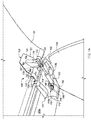
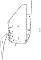
- FIG. 1A is a perspective view of an installed quick release bracket hinge assembly 110, for example a bracket hinge assembly 300 (See FIG. 3A ), connecting a storage bin door (bin door) 102, shown in an open configuration, to an overhead storage bin (storage bin) 106 for a commercial aircraft interior according to an example embodiment.
- the installed bracket hinge assembly 110 includes a shroud 1 12 covering components of the bracket hinge assembly 110, for example to prevent pinching of passenger items within the mechanisms or to protect from dust or damage to the mechanisms.
- the bracket hinge assembly 110 can be configured for use with existing hinge hardware.
- the shroud 1 12 can include one or more apertures 118 to secure a pre-existing strut assembly 150 (discussed in greater detail below in relation to FIG. 1 C) , and a pair of projections 116a-b to accommodate portions of the individual components of the bracket hinge assembly 110.
- the preexisting bin door hardware configured for mating with the bracket hinge assembly 110 may include a bin door hinge 108 (discussed in greater detail below in relation to FIG. IB) including a bin mount 130 hingedly connected to a door mount 120, for example with at least one pin 140.
- a bin door hinge 108 discussed in greater detail below in relation to FIG. IB
- a bin mount 130 hingedly connected to a door mount 120, for example with at least one pin 140.
- the door mount 120 can have a curved structure 122 configured to complement a curvature of the bin door 102.
- the door mount 120 can secure to the bin door 102 using a set of fasteners through a set of apertures 142 of the curved structure 122.
- the bin door 102 is hinged in such a manner as to permit maximum access to an interior of the storage bin 106 when the bin door 102 is open in order to facilitate placement into and removal from the storage bin 106 of passenger luggage items.
- the bin door 102 swings upwards at a hinge assembly including mated hinge elements 132, 134, 140, and the gas strut 149 of the gas strut assembly 150 extends, pushing out a piston 156 to assist in lifting the bin door 102 toward a ceiling of the aircraft cabin.
- the piston 156 of the strut assembly 150 pushes into the gas strut 149, dampening closing and loading a spring mechanism that assists during re-opening.
- bracket assembly 110 is included to extend the position of the strut assembly 150 outward toward an aisle from a conventional mounting position proximate a rear of the shroud 1 12, providing increased bin storage capacity.
- Other benefits of such bracket assemblies 1 10 are described below in example embodiments of FIGs. 2A through 2D and FIGs. 3A through 3C .
- FIGs. 2A through 2D illustrate a first example of a bracket hinge assembly providing increased capacity for a storage bin and also enabling a maintenance position for more readily accessing a ceiling panel mounted above the storage bin (e.g., storage bin 106 of FIG. 1A ).
- a pivot mount 204 is attached to the upper surface of the storage bin.
- a hinge body member 202 extends from the pivot mount 204 toward the door of the storage bin, the hinge body member having a first portion 252 rotatably coupled to the piston mount 204 and having a second portion 230 releaseably attached to the upper surface of the storage bin such that the second portion can pivot downwardly when the second portion is released from the upper surface.
- the piston member 150 is carried by the hinge body member 202 and has a first end 280c coupled to the hinge body member and a second end 154 coupled to the door such that the piston member is carried downwardly when the hinge body member pivots downwardly.
- the piston member 150 actuates as the door is moved from the closed position to an open position.
- An extension member 220 bridges a gap between the door and the upper surface of the storage bin, the extension member having an end hingedly coupled to the door.
- the gap corresponds to a distance that an upper edge of the door is positioned laterally relative to a position of the edge prior to installation of said extension member, such that the enclosed storage bin space is larger relative to the storage bin space prior to installation of said extension member, wherein the hinge body member is configured to permit the door to be translated downwardly to permit access to and removal of ceiling panels without decoupling the door from the storage bin.
- a mounting position 164 of the first end 160 of the piston member is adjustable relative to the hinge body member.
- the extension member 220 may integrally formed with the hinge body member or formed as a separate piece.
- the hinge body member 202 may releasably attached to the upper surface of the storage bin via at least one flange 312 extending from the upper surface of the storage bin.
- the hinge body member 202 may be released from the upper surface of the storage bin by removal of at most two pins or fasteners installed in apertures 314, 364.
- a shroud member 1 10 may substantially cover the hinge body member 202 or the pivot member.
- the enclosed storage bin space may be at least 5 percent or 10 percent larger relative to the storage bin space prior to installation of said extension member.
- the retrofitting method described herein may increase the storage bin space by at least 1 , 2, 3, 4, 5, 6, 7, 8, 9, 10, 11 , 12, 13, 14, 15, 16, 17, 18, 19, or 20 percent.
- the storage bin may be equipped with a second hinge body member, a second piston member and a second extension member spanning the gap.
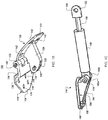
- FIG. 2A is a perspective view of an example bracket hinge assembly 200 including a bracket extension 202 and a pivot anchor 204 according to an embodiment.
- the bracket hinge assembly 200 may be compatible with the shroud 1 12 of FIG. 1A for use as the bracket hinge assembly 110.
- FIGs. 2B and 2C are a side view and top view, respectively, of the bracket extension 202 of FIG. 2A according to an example.
- the bracket extension 202 can include a mating end 220 having a set of apertures 224, arranged in substantially the same configuration and spacing as a set of apertures 136 of the bin mount 130 (FIG. IB), and a pair of protrusions 222a-b configured to compliment a tapered shape 134 of the bin mount 130.
- the pair of raised guides 222a-b can facilitate alignment of the set of apertures 136 of the bin mount 130 and the set of apertures 224 of the mating end 220 of the bracket extension 202.
- the mating end 220 can include a riser 228 separating the mating end 220, laterally, relative to the extender 240 by a displacement height 264.
- the height displacement provided by the riser 228, for example, allows for disposition of the protrusions 222a, 222b between a horizontal surface of the mating end 220 and the vertical surface of the rise 228.
- the riser 228 allows the extension arm 240 to be configured in a different lateral plane than horizontal surface of the mating end 220. This may provide for clearance between the bracket assembly 200 and the curved profile of the inner surface of the storage bin 106. As illustrated in FIG.
- a pair of diagonal support members 226a are disposed between the riser 228 and the mating end 220, for example to provide additional structural support and integrity to the stepped shape of the mating end 220.
- the diagonal support members for example, create a set of triangular exterior walls parallel to the protrusions 222a, 222b and disposed along opposing edges of the mating end 220.
- the mating end 220 of the bracket extension 202 can connect to an extender 240 with a bin mounting surface 230.
- the bin mounting surface 230 can include a set of apertures 232 arranged in substantially the same configuration and spacing as the set of apertures 136 of the bin mount 130.
- the set of apertures 232 of the bin mounting surface 230 can be used to secure the bracket extension 202 to an upper interior surface of the storage bin 106 using the existing mounting locations previously securing the bin mount 130 in position, and a set of fasteners 280a (illustrated as screws in FIG. 2D ) which may be the same fasteners previously securing the bin mount 130 in this location.
- Closing and opening of the door 102 can be assisted with use of the gas strut assemblyl50 that can help lift and hold the bin door 102 in the open position as well as dampen during a closing movement.
- the door mount 120 as shown in FIG. IB, includes a channel 126 at a distal end of a central flange 124 that is intersected by an aperture 128 orthogonal to the channel 126.
- the gas strut assembly 150 includes a piston end 156 with a flattened distal connector 152 configured to slide into the channel 126 of the door mount 120, as illustrated in FIG. 1A .
- the flattened distal connector 152 includes an aperture 154 configured to align and secure with the aperture 128 of the central flange 124 according to an example.
- the gas strut assembly 150 can be secured to an upper interior surface of the storage bin 106 using a pivoting anchor 160.
- the pivoting anchor 160 can be configured to connect to the gas strut 149 using a pin 170 that intersects the gas strut 149 and a pair of flanges 162a-b of the pivoting anchor 160.
- the gas strut 149 connects to the extender 240 of the bracket extension 202 with an adjustment plate 168.
- the pivoting anchor 160 can include one or more apertures 166 and a scaled or ridged surface 164 configured to lock into a complementary scaled or ridged surface of the adjustment plate 168 for preventing slippage and preventing aligned parts from moving laterally.
- the fasteners securing the adjustment plate 168 can be loosened and the pivoting anchor 160 can be re-secured to the adjustment plate 168 at a different point along their scaled surfaces 164, 168.
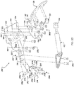
- FIG. 2D is an exploded view of the bracket hinge assembly 200 including the bracket extension 202 and the pivot anchor 204 configured to secure to existing bin door hardware such as the bin mount 130 and strut assembly 150. As shown in FIG. 2D , alignments are illustrated between the bracket hinge assembly 200 and each of the bin mount 130 and the strut assembly 150.
- the bin door hinge 108 includes the bin mount 130 hingedly connected to the door mount 120, for example with the pin 140.
- the bin mount 130 includes the set of apertures 136 and is configured to secure to the mating end 220 of the bracket extension 202 using a set of fasteners 280d.
- the bin mount 130 can have a stepped surface 138 configured to elevate a connecting portion 132 for receiving the pin 140.
- the bin mount 130 can have the tapered surface 134 opposite the end mating the door mount 120.
- the tapered surface 134 may originally have configured to fit a groove in the storage bin 106 for a securing.
- the door mount 120 is configured to connect to the strut assembly 150 by pairing apertures 128 and 154.
- the strut assembly 150 may be connected to the door mount 120 via a pin or another fastener.
- the strut assembly 150 is configured to connect to a raised member 242 of the extension arm 240 via a set of apertures 244 within the raised member which provide a mating surface for apertures of the pivoting anchor 160 of the strut assembly 150.
- the raised member 242 extends substantially from an end of the extension arm connecting to the bin mounting surface 230 to a position between the pair of flanges 250a, 250b of the pivoting second end 252 of the bracket extension 202.
- the raised member 242 may provide stability and separation to the pair of flanges 250a, 250b as well as an enforced mounting surface for connecting to the strut assembly 150.
- the raised member 242 receives fasteners 280c extending through the pivot anchor 160 of the strut assembly 150 without allowing the fasteners 280c to extend through the bracket assembly 200 to a position proximate the inner upper surface of the storage bin.
- the raised member 242 is partially hollow, for example to reduce weight.
- the raised member 242 extends across a central axis of the bin mounting surface 230 in an extension wedge 242a of the raised member 242.
- the extension wedge 242a may provide additional structural stability and strength to the extension arm 240.
- the strut assembly 150 In connecting the strut assembly 150 to the extension arm 240 rather than to its conventional mounting position on the inner upper surface of the bin door, for example, the strut assembly 150 is extended in position toward the bin door 102.
- the relocation of the strut assembly 150 for example, enables adjustment of the extension of the bin door 102 relative to its conventional range of motion.
- the pivoting second end 252 of the bracket assembly 200 is configured for installation in a position formerly mating with the pivot anchor 160 of the strut assembly 150.
- the pivot anchor 204 of the bracket assembly 200 includes a pair of parallel flanges 210a, 210b connected by a mounting surface 211 including a mounting aperture 214.
- the pivot anchor 2014 may be configured for releasable attachment to the upper inner surface 106a of the storage bin 106 (e.g., around reference 112 of FIG. 1A ) using a set of fasteners 280b configured to connect with the upper inner surface 106a of the storage bin 106 through the apertures 214 of the mounting surface 211 of the pivot anchor 204.
- the pivot anchor 204 may be configured to pivotably connect to a pivoting second end 252 of the bracket extension 202.
- the bracket extension 202 includes a pair of flanges 254 opposite the mating end 220 of the bracket extension 202.
- the pair of flanges 254 are parallel and separated by the extender 240.
- Each flange 254a, 254b includes a corresponding aperture 254a, 254b orthogonally positioned in each flange 254a, 254b such that a pin may be extended through the apertures 254a, 254b perpendicular to a longitudinal axis of the extender 240.
- the flanges 254a, 254b may mount between the flanges 210a, 201b of the pivot anchor 204 such that the apertures 212a, 212b of the pivot anchor are in alignment with the apertures 254a, 254b of the bracket extension 202.
- At least one pin mechanism may pivotally connect the pivot anchor 204 to the bracket extension 202 about the apertures 212a, 212b, 254a, and 254b.
- a pin 282a may pivotably connect apertures 212a and 254a
- a second pin 282b may pivotably connect apertures 212b and 254b such that the mating end 220 of the bracket extension 202 can rotate down in a maintenance mode (see FIGs.
- the maintenance mode is configured to place the bin door 102a in a swing away position, thereby facilitating ceiling panel removal.
- the fasteners 280a connecting the bracket extension 202 to the upper interior surface of the storage bin 106 may be disconnected, allowing the mating end 220 to drop downward via the pivot anchor 204.
- the mating end 220 of the extension bracket 200 can have a length 262 and width 272 configured to secure to the door mount 120 of the bin door hinge 108 (shown in FIG. 1A ).
- the extender 240 has a length 266, providing for a combined extension bracket length of 274.
- the length 274 may provide reconfiguration of a mounting position of an upper edge 602a of a bin door 602a (shown in FIG. 6B ) such that mounting angle of the bin door 602a is reduced, providing additional volume within the storage bin.
- the door mount 130 connects to the mating end 220 of the extension bracket 200 which extends between the door mount 130 and the prior mounting position of the strut assembly 150.
- This allows for shifting of the mounting positions of the strut assembly 150 and the door mount 130 by approximately a length between the position of the pivot anchor 204 (e.g., about the pivot end 252 of the hinge assembly 200 and a position of the apertures 244 of the extension arm 240, providing connection to the strut assembly 150. This is illustrated, for example, in FIG. 2B as a length 276.
- portions of the bracket hinge assembly 200, 300 can be formed from a stamped metal such as aluminum, or from a mold or 3D printed part using a plastic and/or composite material.
- portions of the existing hardware ban be combined with portions of the bracket hinge assembly 200, 300 to make a single unit (not shown).
- the bracket extension 202 can be combined with the bin mount 130 of the bin door hinge 108.
- bracket extension 202 To enable interoperability of the bracket extension 202 with preexisting bracket hinge assemblies of various manufacturers, in some embodiments, a greater number of apertures are provided on the bracket extension 202 than required for interfacing with various bin door attachments, thus enabling manufacture of a same apparatus for installation in a variety of storage bin configurations.
- apertures of the bracket extension may be provided in elongated slots or ovals such that the apertures of the bracket extension tolerate minor misalignment with the bin door attachment.
- a method for retrofitting an aircraft cabin with the bracket hinge assembly 200 of FIG. 2A may include detaching the pivoting anchor 160 connecting the gas strut assembly 150 from an upper surface of a stowage bin.
- the method may further include unfastening a bin door hinge 108 from a mounting position on the upper surface of the stowage bin.
- the method may include installing the pivoting anchor 160 connecting the gas strut assembly 150 to the bracket extension 202.
- the gas strut assembly 150 may connect to the extender 240 of the bracket extension 202 via at least one fastener aperture, such as the set of apertures 244 illustrated in FIG. 2D .
- the method may further include fastening the bin door hinge 108 to the mating end 220 of the bracket extension 202.
- the bin door hinge 108 may connect to the bracket extension 202 via the apertures 136 of the bin mount 130 aligning with mated apertures 224 of the mating end 220 of the bracket extension 202.
- the method may further include connecting the pivot anchor 204 to the end of the bracket extension 202.
- the bracket extension 202 for example may be pivotally attached to apertures 212 of the pivot anchor 204 via apertures 254 using a pivoting fastener such as one or more pins 282.
- the method may include fastening the pivot anchor 204 to a position on the upper surface of the stowage bin proximate a former mounting location of the gas strut assembly 150.
- apertures configured to mate with fasteners 280b used to connect the gas strut assembly 150 to the upper surface of the stowage bin may be repurposed for connecting the pivot anchor 204 to the upper surface of the stowage bin.
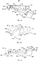
- a quick release bracket hinge assembly 300 can include a quick release to lower down the bin door 102 into the maintenance mode (See FIGs. 4B , 7 ).
- a quick release bracket hinge assembly 300 can include a bin bracket 304 configured to secure to an upper interior surface of the storage bin 106 and a quick release bracket extension 302 configured to connect to the door mount 120 of the bin door hinge 108.
- the bin bracket 304 replaces the pivot anchor 204 and the quick release bracket extension 302 replaces the bracket extension 202.
- FIG. 3B a top left perspective drawing of a bin bracket 304 is shown having a first end 310 including a pair of flanges 312a-b on each lateral side, each flange 312a-b having an aperture 314a-b, as well as a set of apertures 316 configured to secure to the bin mount 130 using a set of fasteners 280d (see FIG. 2D ).
- the first end 310 can include central aperture 318 for structural support.
- the pair of flanges 312a-b of the first end 310 can extend to a bin mounting section 320 of the bin bracket 304 which includes a set of apertures 322 arranged in substantially the same configuration and spacing as the set of apertures 136 of the bin mount 130 which are configured to align with the existing mounting locations previously securing the bin mount 130 in position, to attach the bin bracket 304 to the storage bin 106 using the set of fasteners 280a ( FIG. 2D ) which may be the same fasteners previously securing the bin mount 130 in this location.
- the bin mounting section 320 can include an elongated aperture 324 configured to adjust an attachment location of variations of a bin bracket and storage bin combination.
- the bin bracket 304 can include a second end 330 tapering 332 from the bin mounting section 320, which includes a pair of flanges 332a-b on each lateral side, each flange 332a-b having an aperture 334a-b according to an example.
- FIG. 3C is a side view illustration of a bracket extension 302 including a mating end 350, an extending section 360 having a pair of flanges 362a, 362b, and a pivoting second end 370 having a pair of flanges 372a-b configured to complement the pair of flanges 332a-b of the bin bracket 304 according to an example.
- the mating end 350 includes a set of apertures 352 arranged in substantially the same configuration and spacing as the set of apertures 136 of the bin mount 130.
- the extending section 360 further includes a set of apertures 366 arranged in substantially the same configuration and spacing as the adjustment plate 168 and the pivoting anchor 160 of the strut assembly 150.
- the set of apertures 366 can be securing locations for the strut assembly 150 according to an example.
- spacing of the pair of flanges 372a-b is configured to be more narrow than the pair of flanges 332a-b.
- each flange 362a, 362b has an aperture 364 configured to align with the aperture 314 of the flange 312 of the first end of the bin bracket 304.
- the aperture 334 of the bin bracket 304 is configured to secure to an aperture 374a-b of the pivoting second end 370 of the bracket extension 302, while also forming a joint for rotation.
- the bin bracket 304 and the bracket extension 302 can be secured at the apertures 314a-b, 364a-b using a pin, rod, or other quick release mechanism.
- the mating end 350 can be structurally reinforced by a pair of extensions 368a-b connecting each flange 362a, 362b to both lateral sides of the mating end 350.
- a flange 362c extending from the extending section 360 to the mating end 350 can also provide mechanical support to the mating end 350.
- the pair of flanges 362 are parallel and separated by the mating end 350.
- Each flange 362a, 362b includes a corresponding aperture 364a, 364b orthogonally positioned in each flange 362a, 362b such that a pin may be extended through the apertures 364a, 364b perpendicular to a longitudinal axis of the mating end 350.
- the flanges 372a, 372b may mount between the flanges 332a, 332b of the bin bracket 304 such that the apertures 314a, 314b of the bin bracket 304 are in alignment with the apertures 362a, 362b of the bracket extension 302.
- At least one pin mechanism may pivotally connect the bin bracket 304 to the bracket extension 302 about the apertures 314a, 314b, 362a, and 362b.
- a first pin 306, or alternatively a pair of plugs may pivotably connect apertures 334a,372a and 334b, 372b
- a second pin, or alternatively a pair of plugs may pivotably connect apertures 314a, 364a, and 314b, 364b such that the mating end 350 of the bracket extension 302 can rotate down in a maintenance mode (see FIGs. 4B , 7 ).
- a method for retrofitting an aircraft cabin with the bracket hinge assembly of FIGs. 3A- 3C may include detaching a pivoting anchor 160 connecting the gas strut assembly 150 to an upper surface of a stowage bin.
- the method may further include unfastening a bin door hinge 108 from a mounting position on the upper surface of the stowage bin.
- the method may include installing the pivoting anchor 160 connecting the gas strut assembly 150 to the quick release bracket extension 302.
- the pivot anchor 160 of the gas strut assembly 150 may connect to the extending section 360 of the quick release bracket extension 302 via at least one fastener aperture 366.
- the method may further include fastening the bin door hinge 108 to the mating end 350 of the quick release bracket extension 302.
- the bin door hinge 108 may connect to the quick release bracket extension 302 via apertures 136 of the bin mount 130 aligning with mated apertures 352 of the mating end 350 of the quick release bracket extension 302.
- the method may further include connecting the bin bracket 304 to the end 370 of the quick release bracket extension 302.
- the quick release bracket extension 302 may be pivotally attached to apertures 374 of the bin bracket 304 via apertures 334 using a pivoting fastener such as one or more pins.
- the method may include fastening the bin bracket 304 to a position on the upper surface of the stowage bin proximate a former mounting location of the gas strut assembly 150.
- apertures configured to mate with fasteners used to connect the gas strut assembly 150 to the upper surface of the stowage bin may be repurposed for connecting the bin bracket 304 to the upper surface of the stowage bin via aperture 324.
- a bin door 402a is connected to a storage bin using a bracket assembly for extending the hinge position of the bin door 402a, such as the bracket assembly 200 described in relation to FIGS. 2A-D or the bracket assembly 300 described in relation to FIGs. 3A-C .
- FIG. 4A illustrates a difference between a bin door 402b, having an existing bin door orientation, and bin door 402a mounted with a bracket extension assembly, thus forming an extra volume produced by a gap 410 between a former mounting position and the present mounting position.
- a mounting angle of the bin door 402a is adjusted within a range of about 5 degrees closer to vertical to 20 degrees closer to vertical.
- the bracket hinge assembly 200 or 300 may modify the mounting angle of the bin door 402a by at least 12 degrees closer to vertical.
- the gap 410 may provide clearance to an upper set of canyon luggage wheels or other carry on item feature that may not otherwise be afforded clearance when the bin door is mounted at the steeper angle illustrated in FIG. 4A .
- FIG. 4A illustrates the gap 410 between the bin doors 402a, 402b as an opening for viewing within the stowage bin interior space, it may be noted that, in an installed configuration, each stowage bin may be configured with the same bracket hinge extension apparatus such that the bin doors 402 are in alignment in the closed (stowed) position.
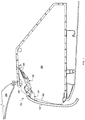
- FIG. 4B The maintenance mode is shown in FIG. 4B , demonstrating a perspective view of a bin door 402a connected to a storage bin 406 using the quick release bracket hinge assembly 300, where the quick release bracket extension 302 is shown pivoted downward 420, thereby lowering the bin door 402a according to an example.
- the bin door 402a may be lowered by at least 1 inch, at least two inches, or over three inches vertically using the quick release bracket hinge assembly 300.
- FIG. 4C is an enlarged perspective view of the quick release bracket hinge assembly 300 showing the bin bracket 304 and the bracket extension 302 secured at the apertures 334,374 and released at the apertures 314, 364.
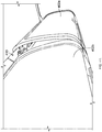
- FIG. 5A is a cross-section of a portion of an aircraft compartment including a ceiling panel section 510, a storage bin section 520 having a front bin edge 522, and a hinge portion connecting a bin door 502 to the storage bin using existing hinge hardware according to an example.
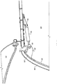
- FIG. 5B is an enlarged view of a hinge portion of FIG. 5A showing the bin door 502 connected to the bin door hinge 108 and strut assembly 150 according to an example.
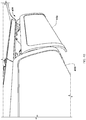
- FIG. 6A is a cross-section of a portion of an aircraft compartment including a ceiling panel section 610, a storage bin section 620 having a front bin edge 622, and a hinge portion connecting a bin door 602 to the storage bin using the bracket hinge assembly 300 shown in FIGs. 3A-3C according to an example.
- FIG. 6B is an enlarged view of a hinge portion of FIG. 6A showing the bin door 602 connected to the storage bin using the bracket hinge assembly 300, the bin door hinge 108, and strut assembly 150 according to an example.
- the bin door 602 is noticeably separated from the front bin edge 622 of the storage bin section 620 providing extra storage space 630.
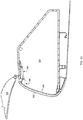
- FIG. 7 shows the bin door 102 placed in a maintenance mode 700.
- the quick release bracket hinge assembly 300 is configured to pivot downwardly and place the bin door 102 in a maintenance mode 700.
- bracket hinge assembly 200 of FIG. 2A and the quick release bracket hinge assembly 300 of FIG. 3A may provide the benefits of increased storage volume in overhead stowage bins through decreasing a mounting angle of the bin door of the stowage compartment. Due to the decrease in mounting angle, for example, the bracket hinge assemblies may provide additional clearance for upper wheels of a wheeled luggage, handles, or other features of carry-on passenger items.
- the bracket hinge assembly 200 of FIG. 2A and the quick release bracket hinge assembly 300 of FIG. 3A may be designed for retrofit replacement using preexisting bin door hardware such that only a portion of the preexisting bin door securing apparatus is replaced. Further, in some implementations, one or more fastener apertures or other bracket features may be designed for interoperability with preexisting hardware supplied by various original equipment manufacturers (OEMs). In this manner, the bracket hinge assemblies 1 10, 200, 300 may be universally installed as retrofit solutions in existing passenger cabin configurations.
- OEMs original equipment manufacturers
Landscapes
- Engineering & Computer Science (AREA)
- Aviation & Aerospace Engineering (AREA)
- Mechanical Engineering (AREA)
- Hinges (AREA)
- Pressure Vessels And Lids Thereof (AREA)
Claims (15)
- Aufbewahrungsfach in einem Flugzeug, das Folgendes umfasst:ein Aufbewahrungsfach (106, 406), umfassend eine obere Oberfläche;eine Klappe (102, 102a; 402, 402a; 502; 602; 602a), angelenkt mit dem Aufbewahrungsfach gekoppelt, wobei die Klappe (102, 102a; 402, 402a; 502; 602; 602a) und das Aufbewahrungsfach (106, 406) zumindest teilweise einen eingeschlossenen Aufbewahrungsfachraum definieren, wenn die Klappe (102, 102a; 402, 402a; 502; 602; 602a) in einer geschlossenen Position ist;eine Schwenkbefestigung (204), befestigt an der oberen Oberfläche des Aufbewahrungsfachs (106, 406);ein Scharnierkörperelement (202), das sich von der Schwenkbefestigung (204) in Richtung der Klappe (102, 102a; 402, 402a; 502; 602; 602a) des Aufbewahrungsfachs (106, 406) erstreckt, wobei das Scharnierkörperelement (202) einen ersten Teil (252) aufweist, der drehbar mit der Schwenkbefestigung gekoppelt ist;ein Kolbenelement (150), getragen durch das Scharnierkörperelement (202), wobei das Kolbenelement (150) ein erstes Ende (160, 280c), gekoppelt mit dem Scharnierkörperelement (202), und ein zweites Ende (154, 252), gekoppelt mit der Klappe (102, 102a; 402, 402a; 502; 602; 602a), aufweist, sodass das Kolbenelement abwärts befördert wird, wenn das Scharnierkörperelement nach unten schwenkt, wobei das Kolbenelement (150) betätigt wird, wenn die Klappe (102, 102a; 402, 402a; 502; 602; 602a) aus der geschlossenen Position in eine offene Position bewegt wird; undein Verlängerungselement (220), das eine Lücke zwischen der Klappe (102, 102a; 402, 402a; 502; 602; 602a) und der oberen Oberfläche des Aufbewahrungsfachs überbrückt, wobei das Verlängerungselement (220) ein Ende aufweist, das angelenkt mit der Klappe (102, 102a; 402, 402a; 502; 602; 602a) gekoppelt ist;wobei die Lücke einem Abstand entspricht, mit dem eine obere Kante (602a) der Klappe vor der Installation des Verlängerungselements (220) lateral relativ zu einer Position der oberen Kante (602a) positioniert ist, sodass das eingeschlossene Aufbewahrungsfachraum relativ zum Aufbewahrungsfachraum vor der der Installation des Verlängerungselements (220) größer ist,dadurch gekennzeichnet, dass das Scharnierkörperelement (202) einen zweiten Teil (230) aufweist, der lösbar an der oberen Oberfläche des Aufbewahrungsfachs (106, 406) befestigt ist, sodass der zweite Teil (230) nach unten schwenken kann, wenn der zweite Teil (230) von der oberen Oberfläche gelöst wird.
- Aufbewahrungsfach nach Anspruch 1, wobei das Scharnierkörperelement (202) dazu ausgelegt ist, der Klappe (102, 102a; 402, 402a; 502; 602; 602a) zu ermöglichen, nach unten verschoben zu werden, um Zugang zu und Entfernung von Deckentafeln zu ermöglichen, ohne die Klappe (102, 102a; 402, 402a; 502; 602; 602a) vom Aufbewahrungsfach (106, 406) zu entkoppeln.
- Einrichtung nach Anspruch 1 oder 2, wobei eine Montageposition des ersten Endes (160, 280c) des Kolbenelements relativ zum Scharnierkörperelement einstellbar ist und/oder wobei das Verlängerungselement (220) integral mit dem Scharnierkörperelement (202) ausgebildet ist.
- Einrichtung nach einem der Ansprüche 1-3, wobei das Scharnierkörperelement (202) über zumindest einen Flansch (312, 312a, 312b), der sich von der oberen Oberfläche des Aufbewahrungsfachs (106, 406) erstreckt, lösbar an der oberen Oberfläche des Aufbewahrungsfachs (106, 406) befestigt ist.
- Einrichtung nach einem der Ansprüche 1-4, wobei das Scharnierkörperelement (202) durch Entfernung von höchstens zwei Stiften oder Befestigungselementen von der oberen Oberfläche gelöst werden kann.
- Einrichtung nach einem der Ansprüche 1-5, ferner umfassend ein Verkleidungselement (110), das im Wesentlichen das Scharnierkörperelement (202) und das Schwenkelement abdeckt.
- Einrichtung nach einem der Ansprüche 1-6, wobei das eingeschlossene Aufbewahrungsfachraum relativ zum Aufbewahrungsfachraum vor Installation des Verlängerungselements (220) mindestens 5 Prozent, vorzugsweise mindestens 10 Prozent, größer ist.
- Einrichtung nach einem der Ansprüche 1-7, ferner umfassend ein zweites Scharnierkörperelement, ein zweites Kolbenelement und ein zweites Verlängerungselement, das die Lücke überspannt.
- Verfahren zum Nachrüsten eines Aufbewahrungsfachs in einem Flugzeug (106, 406), umfassend eine obere Oberfläche und eine Klappe (102, 102a; 402, 402a; 502; 602; 602a), angelenkt mit dem Aufbewahrungsfach (106, 406) gekoppelt, wobei die Klappe (102, 102a; 402, 402a; 502; 602; 602a) und das Aufbewahrungsfach (106, 406) zumindest teilweise einen eingeschlossenen Aufbewahrungsfachraum definieren, wenn die Klappe (102, 102a; 402, 402a; 502; 602; 602a) in einer geschlossenen Position ist, wobei das Verfahren Folgendes umfasst:Installieren einer Schwenkbefestigung (204), befestigt an der oberen Oberfläche des Aufbewahrungsfachs (106, 406);Installieren eines Scharnierkörperelements (202), das sich von der Schwenkbefestigung (204) in Richtung der Klappe des Aufbewahrungsfachs (106, 406) erstreckt, wobei das Scharnierkörperelement (202) einen ersten Teil (252) aufweist, der drehbar mit der Schwenkbefestigung (204) gekoppelt ist, und einen zweiten Teil aufweist, der lösbar an der oberen Oberfläche des Aufbewahrungsfachs befestigt ist, sodass der zweite Teil nach unten schwenken kann, wenn der zweite Teil von der oberen Oberfläche gelöst wird;Installieren eines Kolbenelements (150), getragen durch das Scharnierkörperelement (202), wobei das Kolbenelement (150) ein erstes Ende (160, 280c), gekoppelt mit dem Scharnierkörperelement (202), und ein zweites Ende (154, 252), gekoppelt mit der Klappe (102, 102a; 402, 402a; 502; 602; 602a), aufweist, sodass das Kolbenelement (150) abwärts befördert wird, wenn das Scharnierkörperelement (202) nach unten schwenkt, wobei das Kolbenelement (150) betätigt wird, wenn die Klappe (102, 102a; 402, 402a; 502; 602; 602a) aus der geschlossenen Position in eine offene Position bewegt wird; undInstallieren eines Verlängerungselements (220), das eine Lücke zwischen der Klappe (102, 102a; 402, 402a; 502; 602; 602a) und der oberen Oberfläche des Aufbewahrungsfachs (106, 406) überbrückt, wobei das Verlängerungselement (220) ein Ende aufweist, das angelenkt mit der Klappe (102, 102a; 402, 402a; 502; 602; 602a) gekoppelt ist;wobei die Lücke einem Abstand entspricht, mit dem eine obere Kante (602a) der Klappe vor der Installation des Verlängerungselements (220) lateral relativ zu einer Position der oberen Kante (602) positioniert ist, sodass das eingeschlossene Aufbewahrungsfachraum relativ zum Aufbewahrungsfachraum vor der der Installation des Verlängerungselements (220) größer ist,dadurch gekennzeichnet, dass das Scharnierkörperelement (202) einen zweiten Teil (230) aufweist, der lösbar an der oberen Oberfläche des Aufbewahrungsfachs (106, 406) befestigt ist, sodass der zweite Teil (230) nach unten schwenken kann, wenn der zweite Teil (230) von der oberen Oberfläche gelöst wird.
- Verfahren nach Anspruch 9, wobei das Scharnierkörperelement (202) dazu ausgelegt ist, der Klappe (102, 102a; 402, 402a; 502; 602; 602a) zu ermöglichen, nach unten verschoben zu werden, um Zugang zu und Entfernung von Deckentafeln zu ermöglichen, ohne die Klappe (102, 102a; 402, 402a; 502; 602; 602a) vom Aufbewahrungsfach (106, 406) zu entkoppeln.
- Verfahren nach Anspruch 9 oder 10, wobei eine Montageposition des ersten Endes (160, 280c) des Kolbenelements relativ zum Scharnierkörperelement (202) einstellbar ist und/oder wobei das Verlängerungselement (220) integral mit dem Scharnierkörperelement (202) ausgebildet ist.
- Verfahren nach einem der Ansprüche 9-11, wobei das Scharnierkörperelement (202) über zumindest einen Flansch (312, 312a, 312b), der sich von der oberen Oberfläche des Aufbewahrungsfachs (106, 406) erstreckt, lösbar an der oberen Oberfläche des Aufbewahrungsfachs (106, 406) befestigt ist, und/oder wobei das Scharnierkörperelement (202) durch Entfernung von höchstens zwei Stiften oder Befestigungselementen von der oberen Oberfläche des Aufbewahrungsfachs gelöst werden kann.
- Verfahren nach einem der Ansprüche 9-12, ferner umfassend Installieren eines Verkleidungselements (110), das im Wesentlichen das Scharnierkörperelement (202) und das Schwenkelement abdeckt.
- Verfahren nach einem der Ansprüche 9-13, wobei das nachgerüstete eingeschlossene Aufbewahrungsfachraum relativ zum Aufbewahrungsfachraum vor Installation des Verlängerungselements (220) mindestens 5 Prozent, vorzugsweise mindestens 10 Prozent, größer ist.
- Verfahren nach einem der Ansprüche 9-14, ferner umfassend Installieren eines zweiten Scharnierkörperelements, eines zweiten Kolbenelements und eines zweiten Verlängerungselements, das die Lücke überspannt.
Applications Claiming Priority (2)
| Application Number | Priority Date | Filing Date | Title |
|---|---|---|---|
| US201662316929P | 2016-04-01 | 2016-04-01 | |
| PCT/US2017/025660 WO2017173431A1 (en) | 2016-04-01 | 2017-04-01 | Hinge for enlarging the volume of an aircraft storage bin |
Publications (3)
| Publication Number | Publication Date |
|---|---|
| EP3436352A1 EP3436352A1 (de) | 2019-02-06 |
| EP3436352A4 EP3436352A4 (de) | 2019-11-27 |
| EP3436352B1 true EP3436352B1 (de) | 2021-03-31 |
Family
ID=59959119
Family Applications (1)
| Application Number | Title | Priority Date | Filing Date |
|---|---|---|---|
| EP17776894.2A Active EP3436352B1 (de) | 2016-04-01 | 2017-04-01 | Scharnier zur vergrösserung des volumens eines aufbewahrungsfaches in einem flugzeug |
Country Status (4)
| Country | Link |
|---|---|
| US (1) | US10077111B2 (de) |
| EP (1) | EP3436352B1 (de) |
| CN (1) | CN108883832B (de) |
| WO (1) | WO2017173431A1 (de) |
Cited By (1)
| Publication number | Priority date | Publication date | Assignee | Title |
|---|---|---|---|---|
| US11566459B1 (en) | 2021-07-16 | 2023-01-31 | B/E Aerospace, Inc. | Concealed door hinge with shifting pivot point |
Families Citing this family (12)
| Publication number | Priority date | Publication date | Assignee | Title |
|---|---|---|---|---|
| AT515849A1 (de) * | 2014-05-26 | 2015-12-15 | Facc Ag | Überkopf-Gepäckfach |
| CA3047502A1 (en) * | 2016-12-20 | 2018-06-28 | Bombardier Inc. | Hinge assembly |
| CA3068651A1 (en) | 2017-07-17 | 2019-01-24 | Harper Engineering Company | Integrated stowage bin assembly |
| US11293208B2 (en) * | 2018-04-04 | 2022-04-05 | Safran Cabin Inc. | Fixed bin hinge system |
| US10760313B2 (en) * | 2018-11-16 | 2020-09-01 | GM Global Technology Operations LLC | Locking cylinder hinge |
| DE102019004754B4 (de) * | 2019-07-06 | 2021-01-21 | Diehl Aviation Laupheim Gmbh | Scharnier, Staufachanordnung und Umrüstverfahren |
| CN110544396A (zh) * | 2019-08-12 | 2019-12-06 | 南京莱斯信息技术股份有限公司 | 一种飞机泊位引导设备 |
| US11549295B2 (en) * | 2019-08-28 | 2023-01-10 | Gulfstream Aerospace Corporation | Cabinet and method for making the same, and aircraft including a cabinet |
| DE102020102439A1 (de) * | 2020-01-31 | 2021-08-05 | Airbus Operations Gmbh | Staufachanordnung für eine Kabine eines Fahrzeugs |
| DE102020109169A1 (de) * | 2020-04-02 | 2021-10-07 | Airbus Operations Gmbh | Fahrzeugbereich mit Gepäckfach mit vergrößertem Stauraum, und Verfahren zum Einbau und Ausbau eines Deckenpaneels oberhalb eines Gepäckfaches |
| EP4282756B1 (de) * | 2022-05-24 | 2025-10-15 | Airbus Operations GmbH | Gepäckraum, kabinenkomponentenanordnung und flugzeug |
| AT526607B1 (de) | 2022-11-25 | 2024-05-15 | Facc Ag | Überkopf-Gepäckfach für ein Flugzeug |
Family Cites Families (26)
| Publication number | Priority date | Publication date | Assignee | Title |
|---|---|---|---|---|
| US1345194A (en) * | 1920-01-23 | 1920-06-29 | Lewis O Johnson | Table-drawer |
| US2492697A (en) * | 1947-01-08 | 1949-12-27 | Walter C Higley | Accessory drawer |
| US2791681A (en) * | 1953-12-14 | 1957-05-07 | Ajem Lab Inc | Vapor-tight fluorescent lamp fixture |
| US2950157A (en) * | 1955-08-18 | 1960-08-23 | Whirlpool Co | Freezer cabinet shelving |
| US4185415A (en) * | 1978-04-14 | 1980-01-29 | The Boeing Company | Articulated hinge cooperating with an energy storage device capable of automatically opening and holding open an unlatched compartment door |
| US4275942A (en) * | 1978-12-26 | 1981-06-30 | The Boeing Company | Stowage bin mechanism |
| US4490883A (en) * | 1982-09-07 | 1985-01-01 | Gauron Richard F | Fastener for releasably and adjustably connecting two structural members |
| DE3634684A1 (de) * | 1986-10-11 | 1988-04-21 | Vieler Gerd & Bernd Kg | Verkaufstheke mit einer beweglichen verkroepften frontscheibe |
| GB8814865D0 (en) * | 1988-06-22 | 1988-07-27 | Bridport Aviat Products Ltd | Safety visor for overhead luggage bin of passenger aircraft |
| US5129597A (en) * | 1989-02-06 | 1992-07-14 | Deutsche Airbus Gmbh | Ceiling luggage compartment combination for the passenger cabin of an aircraft |
| AT397906B (de) * | 1992-02-20 | 1994-08-25 | Fischer Adv Components Gmbh | Kunststoffbehälter |
| US5639149A (en) * | 1993-05-04 | 1997-06-17 | Hussmann Corporation | Glass front merchandiser with invisible hinge and seals |
| US5593203A (en) * | 1995-06-08 | 1997-01-14 | Abbott; Jay D. | Retrofitted door for open luggage rack on passenger busses |
| US5687929A (en) * | 1995-06-29 | 1997-11-18 | Hexcel Corporation | Extensions for storage bins |
| DE19633469C1 (de) * | 1996-08-20 | 1997-09-04 | Daimler Benz Aerospace Airbus | Vorrichtung zum Halten von Ausrüstungsteilen im oberen Bereich von Passagierkabinen, insbesondere von Gepäckablagen in Flugzeugpassagierkabinen |
| US5711505A (en) * | 1996-09-30 | 1998-01-27 | Tachi-S Co., Ltd. | Slide rail device for jump seat |
| DE19906395A1 (de) * | 1999-02-16 | 2000-08-17 | Vieler Int Kg | Theke zum Darbieten und/oder Verkaufen von Waren |
| US6290175B1 (en) * | 1999-10-20 | 2001-09-18 | Hexcel Corporation | Bin extension for a vehicle |
| AT410657B (de) * | 2001-10-09 | 2003-06-25 | Fischer Adv Components Gmbh | Überkopf-gepäckablagebehälter, insbesondere für flugzeuge |
| US20080174216A1 (en) * | 2007-01-19 | 2008-07-24 | Hussmann Corporation | Hinge pivot arm for a glass-front merchandiser |
| US8091844B1 (en) * | 2008-11-26 | 2012-01-10 | Bragg Dana C | Air conditioner support device |
| US8292376B1 (en) * | 2010-01-27 | 2012-10-23 | Stelmasik Gregory A | Adjustable pivot assist mechanism for an enclosure door of a display case |
| CN102797397A (zh) * | 2011-05-25 | 2012-11-28 | 深圳市长恩实业有限公司 | 活塞型可六向调节的暗藏式铰链 |
| AT513939A1 (de) * | 2013-02-01 | 2014-08-15 | Facc Ag | Überkopf-Gepäckfach für Flugzeuge und Flugzeug mit solchen Überkopf-Gepäckfächern |
| JP5947759B2 (ja) * | 2013-07-23 | 2016-07-06 | 本田技研工業株式会社 | カメラユニット |
| DE102018100674B4 (de) * | 2018-01-12 | 2020-03-05 | Hettich-Oni Gmbh & Co. Kg | Möbelplatte mit einem Scharnier und Möbel mit einer derartigen Möbelplatte |
-
2017
- 2017-04-01 CN CN201780012932.XA patent/CN108883832B/zh active Active
- 2017-04-01 US US15/477,071 patent/US10077111B2/en active Active
- 2017-04-01 WO PCT/US2017/025660 patent/WO2017173431A1/en not_active Ceased
- 2017-04-01 EP EP17776894.2A patent/EP3436352B1/de active Active
Non-Patent Citations (1)
| Title |
|---|
| None * |
Cited By (1)
| Publication number | Priority date | Publication date | Assignee | Title |
|---|---|---|---|---|
| US11566459B1 (en) | 2021-07-16 | 2023-01-31 | B/E Aerospace, Inc. | Concealed door hinge with shifting pivot point |
Also Published As
| Publication number | Publication date |
|---|---|
| CN108883832A (zh) | 2018-11-23 |
| US20170283058A1 (en) | 2017-10-05 |
| EP3436352A4 (de) | 2019-11-27 |
| WO2017173431A1 (en) | 2017-10-05 |
| US10077111B2 (en) | 2018-09-18 |
| CN108883832B (zh) | 2021-07-09 |
| EP3436352A1 (de) | 2019-02-06 |
Similar Documents
| Publication | Publication Date | Title |
|---|---|---|
| EP3436352B1 (de) | Scharnier zur vergrösserung des volumens eines aufbewahrungsfaches in einem flugzeug | |
| JP7114761B2 (ja) | 回転式棚アセンブリ | |
| US7789347B2 (en) | Device for articulating a door of a nacelle of an aircraft and nacelle provided with said articulation device | |
| RU2228881C2 (ru) | Передняя часть корпуса самолета | |
| US9708015B2 (en) | Rear spoiler device for a vehicle | |
| EP0718189A1 (de) | Nachträglicher Innenausbau vom Gepäckablage kompatibel mit bestehendem Träger in einem Flugzeug | |
| US7832685B2 (en) | Stowage bin with shear fittings | |
| EP0876954A2 (de) | Tür mit Zapfenverriegelung für einen Flugzeugnotausgang über einem Flügel | |
| WO2008144025A2 (en) | Rear-mounted aerodynamic structure for truck cargo bodies | |
| US10266121B2 (en) | Stowable stair carrier with lift assist mechanism | |
| CN105730673A (zh) | 改进设计的起落架舱顶部 | |
| BR112015017337B1 (pt) | Compartimentos de bagagem superiores para aviões e avião | |
| JP6483799B2 (ja) | 回転式棚アセンブリ | |
| US8047468B2 (en) | Stowage bin with shear fittings | |
| US11702875B2 (en) | Bifold door with spherical bearing and pin | |
| US12358626B2 (en) | Aircraft overhead luggage bin and method of modifying same | |
| US8262025B2 (en) | Aircraft structure | |
| US9108717B2 (en) | Aircraft cargo door shield | |
| CN117104507A (zh) | 行李舱架、舱室部件组件和飞机 | |
| CN108248497B (zh) | 皮卡车及其厢盖锁紧装置 | |
| HK40069015A (en) | Aircraft overhead luggage bin and method of modifying same | |
| CN215752681U (zh) | 平板货箱和具有其的卡车 | |
| CN220363284U (zh) | 车辆 | |
| US20200023909A1 (en) | Rear spoiler device for a utility vehicle | |
| JP2020147265A (ja) | 車両用荷台のあおり構造 |
Legal Events
| Date | Code | Title | Description |
|---|---|---|---|
| STAA | Information on the status of an ep patent application or granted ep patent |
Free format text: STATUS: THE INTERNATIONAL PUBLICATION HAS BEEN MADE |
|
| PUAI | Public reference made under article 153(3) epc to a published international application that has entered the european phase |
Free format text: ORIGINAL CODE: 0009012 |
|
| STAA | Information on the status of an ep patent application or granted ep patent |
Free format text: STATUS: REQUEST FOR EXAMINATION WAS MADE |
|
| 17P | Request for examination filed |
Effective date: 20180824 |
|
| AK | Designated contracting states |
Kind code of ref document: A1 Designated state(s): AL AT BE BG CH CY CZ DE DK EE ES FI FR GB GR HR HU IE IS IT LI LT LU LV MC MK MT NL NO PL PT RO RS SE SI SK SM TR |
|
| AX | Request for extension of the european patent |
Extension state: BA ME |
|
| DAV | Request for validation of the european patent (deleted) | ||
| DAX | Request for extension of the european patent (deleted) | ||
| A4 | Supplementary search report drawn up and despatched |
Effective date: 20191025 |
|
| RIC1 | Information provided on ipc code assigned before grant |
Ipc: E05D 5/02 20060101ALI20191021BHEP Ipc: B64D 11/00 20060101AFI20191021BHEP Ipc: E05D 3/06 20060101ALI20191021BHEP Ipc: E05D 15/40 20060101ALI20191021BHEP Ipc: E05D 7/00 20060101ALI20191021BHEP Ipc: E05D 5/04 20060101ALI20191021BHEP |
|
| GRAP | Despatch of communication of intention to grant a patent |
Free format text: ORIGINAL CODE: EPIDOSNIGR1 |
|
| STAA | Information on the status of an ep patent application or granted ep patent |
Free format text: STATUS: GRANT OF PATENT IS INTENDED |
|
| INTG | Intention to grant announced |
Effective date: 20201027 |
|
| GRAS | Grant fee paid |
Free format text: ORIGINAL CODE: EPIDOSNIGR3 |
|
| GRAA | (expected) grant |
Free format text: ORIGINAL CODE: 0009210 |
|
| STAA | Information on the status of an ep patent application or granted ep patent |
Free format text: STATUS: THE PATENT HAS BEEN GRANTED |
|
| AK | Designated contracting states |
Kind code of ref document: B1 Designated state(s): AL AT BE BG CH CY CZ DE DK EE ES FI FR GB GR HR HU IE IS IT LI LT LU LV MC MK MT NL NO PL PT RO RS SE SI SK SM TR |
|
| REG | Reference to a national code |
Ref country code: GB Ref legal event code: FG4D Ref country code: CH Ref legal event code: EP |
|
| REG | Reference to a national code |
Ref country code: AT Ref legal event code: REF Ref document number: 1376670 Country of ref document: AT Kind code of ref document: T Effective date: 20210415 |
|
| REG | Reference to a national code |
Ref country code: DE Ref legal event code: R096 Ref document number: 602017035777 Country of ref document: DE |
|
| REG | Reference to a national code |
Ref country code: IE Ref legal event code: FG4D |
|
| REG | Reference to a national code |
Ref country code: LT Ref legal event code: MG9D |
|
| PG25 | Lapsed in a contracting state [announced via postgrant information from national office to epo] |
Ref country code: BG Free format text: LAPSE BECAUSE OF FAILURE TO SUBMIT A TRANSLATION OF THE DESCRIPTION OR TO PAY THE FEE WITHIN THE PRESCRIBED TIME-LIMIT Effective date: 20210630 Ref country code: NO Free format text: LAPSE BECAUSE OF FAILURE TO SUBMIT A TRANSLATION OF THE DESCRIPTION OR TO PAY THE FEE WITHIN THE PRESCRIBED TIME-LIMIT Effective date: 20210630 Ref country code: FI Free format text: LAPSE BECAUSE OF FAILURE TO SUBMIT A TRANSLATION OF THE DESCRIPTION OR TO PAY THE FEE WITHIN THE PRESCRIBED TIME-LIMIT Effective date: 20210331 Ref country code: HR Free format text: LAPSE BECAUSE OF FAILURE TO SUBMIT A TRANSLATION OF THE DESCRIPTION OR TO PAY THE FEE WITHIN THE PRESCRIBED TIME-LIMIT Effective date: 20210331 |
|
| PG25 | Lapsed in a contracting state [announced via postgrant information from national office to epo] |
Ref country code: SE Free format text: LAPSE BECAUSE OF FAILURE TO SUBMIT A TRANSLATION OF THE DESCRIPTION OR TO PAY THE FEE WITHIN THE PRESCRIBED TIME-LIMIT Effective date: 20210331 Ref country code: RS Free format text: LAPSE BECAUSE OF FAILURE TO SUBMIT A TRANSLATION OF THE DESCRIPTION OR TO PAY THE FEE WITHIN THE PRESCRIBED TIME-LIMIT Effective date: 20210331 Ref country code: LV Free format text: LAPSE BECAUSE OF FAILURE TO SUBMIT A TRANSLATION OF THE DESCRIPTION OR TO PAY THE FEE WITHIN THE PRESCRIBED TIME-LIMIT Effective date: 20210331 |
|
| REG | Reference to a national code |
Ref country code: NL Ref legal event code: MP Effective date: 20210331 |
|
| REG | Reference to a national code |
Ref country code: AT Ref legal event code: MK05 Ref document number: 1376670 Country of ref document: AT Kind code of ref document: T Effective date: 20210331 |
|
| PG25 | Lapsed in a contracting state [announced via postgrant information from national office to epo] |
Ref country code: NL Free format text: LAPSE BECAUSE OF FAILURE TO SUBMIT A TRANSLATION OF THE DESCRIPTION OR TO PAY THE FEE WITHIN THE PRESCRIBED TIME-LIMIT Effective date: 20210331 Ref country code: SM Free format text: LAPSE BECAUSE OF FAILURE TO SUBMIT A TRANSLATION OF THE DESCRIPTION OR TO PAY THE FEE WITHIN THE PRESCRIBED TIME-LIMIT Effective date: 20210331 Ref country code: AT Free format text: LAPSE BECAUSE OF FAILURE TO SUBMIT A TRANSLATION OF THE DESCRIPTION OR TO PAY THE FEE WITHIN THE PRESCRIBED TIME-LIMIT Effective date: 20210331 Ref country code: LT Free format text: LAPSE BECAUSE OF FAILURE TO SUBMIT A TRANSLATION OF THE DESCRIPTION OR TO PAY THE FEE WITHIN THE PRESCRIBED TIME-LIMIT Effective date: 20210331 Ref country code: CZ Free format text: LAPSE BECAUSE OF FAILURE TO SUBMIT A TRANSLATION OF THE DESCRIPTION OR TO PAY THE FEE WITHIN THE PRESCRIBED TIME-LIMIT Effective date: 20210331 Ref country code: EE Free format text: LAPSE BECAUSE OF FAILURE TO SUBMIT A TRANSLATION OF THE DESCRIPTION OR TO PAY THE FEE WITHIN THE PRESCRIBED TIME-LIMIT Effective date: 20210331 |
|
| PG25 | Lapsed in a contracting state [announced via postgrant information from national office to epo] |
Ref country code: SK Free format text: LAPSE BECAUSE OF FAILURE TO SUBMIT A TRANSLATION OF THE DESCRIPTION OR TO PAY THE FEE WITHIN THE PRESCRIBED TIME-LIMIT Effective date: 20210331 Ref country code: RO Free format text: LAPSE BECAUSE OF FAILURE TO SUBMIT A TRANSLATION OF THE DESCRIPTION OR TO PAY THE FEE WITHIN THE PRESCRIBED TIME-LIMIT Effective date: 20210331 Ref country code: PL Free format text: LAPSE BECAUSE OF FAILURE TO SUBMIT A TRANSLATION OF THE DESCRIPTION OR TO PAY THE FEE WITHIN THE PRESCRIBED TIME-LIMIT Effective date: 20210331 Ref country code: PT Free format text: LAPSE BECAUSE OF FAILURE TO SUBMIT A TRANSLATION OF THE DESCRIPTION OR TO PAY THE FEE WITHIN THE PRESCRIBED TIME-LIMIT Effective date: 20210802 Ref country code: IS Free format text: LAPSE BECAUSE OF FAILURE TO SUBMIT A TRANSLATION OF THE DESCRIPTION OR TO PAY THE FEE WITHIN THE PRESCRIBED TIME-LIMIT Effective date: 20210731 |
|
| PG25 | Lapsed in a contracting state [announced via postgrant information from national office to epo] |
Ref country code: LU Free format text: LAPSE BECAUSE OF NON-PAYMENT OF DUE FEES Effective date: 20210401 |
|
| REG | Reference to a national code |
Ref country code: DE Ref legal event code: R097 Ref document number: 602017035777 Country of ref document: DE |
|
| REG | Reference to a national code |
Ref country code: BE Ref legal event code: MM Effective date: 20210430 |
|
| PG25 | Lapsed in a contracting state [announced via postgrant information from national office to epo] |
Ref country code: ES Free format text: LAPSE BECAUSE OF FAILURE TO SUBMIT A TRANSLATION OF THE DESCRIPTION OR TO PAY THE FEE WITHIN THE PRESCRIBED TIME-LIMIT Effective date: 20210331 Ref country code: LI Free format text: LAPSE BECAUSE OF NON-PAYMENT OF DUE FEES Effective date: 20210430 Ref country code: MC Free format text: LAPSE BECAUSE OF FAILURE TO SUBMIT A TRANSLATION OF THE DESCRIPTION OR TO PAY THE FEE WITHIN THE PRESCRIBED TIME-LIMIT Effective date: 20210331 Ref country code: CH Free format text: LAPSE BECAUSE OF NON-PAYMENT OF DUE FEES Effective date: 20210430 Ref country code: DK Free format text: LAPSE BECAUSE OF FAILURE TO SUBMIT A TRANSLATION OF THE DESCRIPTION OR TO PAY THE FEE WITHIN THE PRESCRIBED TIME-LIMIT Effective date: 20210331 Ref country code: AL Free format text: LAPSE BECAUSE OF FAILURE TO SUBMIT A TRANSLATION OF THE DESCRIPTION OR TO PAY THE FEE WITHIN THE PRESCRIBED TIME-LIMIT Effective date: 20210331 |
|
| PLBE | No opposition filed within time limit |
Free format text: ORIGINAL CODE: 0009261 |
|
| STAA | Information on the status of an ep patent application or granted ep patent |
Free format text: STATUS: NO OPPOSITION FILED WITHIN TIME LIMIT |
|
| 26N | No opposition filed |
Effective date: 20220104 |
|
| PG25 | Lapsed in a contracting state [announced via postgrant information from national office to epo] |
Ref country code: IE Free format text: LAPSE BECAUSE OF NON-PAYMENT OF DUE FEES Effective date: 20210401 |
|
| PG25 | Lapsed in a contracting state [announced via postgrant information from national office to epo] |
Ref country code: IS Free format text: LAPSE BECAUSE OF FAILURE TO SUBMIT A TRANSLATION OF THE DESCRIPTION OR TO PAY THE FEE WITHIN THE PRESCRIBED TIME-LIMIT Effective date: 20210731 |
|
| PG25 | Lapsed in a contracting state [announced via postgrant information from national office to epo] |
Ref country code: IT Free format text: LAPSE BECAUSE OF FAILURE TO SUBMIT A TRANSLATION OF THE DESCRIPTION OR TO PAY THE FEE WITHIN THE PRESCRIBED TIME-LIMIT Effective date: 20210331 Ref country code: BE Free format text: LAPSE BECAUSE OF NON-PAYMENT OF DUE FEES Effective date: 20210430 |
|
| PG25 | Lapsed in a contracting state [announced via postgrant information from national office to epo] |
Ref country code: CY Free format text: LAPSE BECAUSE OF FAILURE TO SUBMIT A TRANSLATION OF THE DESCRIPTION OR TO PAY THE FEE WITHIN THE PRESCRIBED TIME-LIMIT Effective date: 20210331 |
|
| PG25 | Lapsed in a contracting state [announced via postgrant information from national office to epo] |
Ref country code: HU Free format text: LAPSE BECAUSE OF FAILURE TO SUBMIT A TRANSLATION OF THE DESCRIPTION OR TO PAY THE FEE WITHIN THE PRESCRIBED TIME-LIMIT; INVALID AB INITIO Effective date: 20170401 Ref country code: GR Free format text: LAPSE BECAUSE OF FAILURE TO SUBMIT A TRANSLATION OF THE DESCRIPTION OR TO PAY THE FEE WITHIN THE PRESCRIBED TIME-LIMIT Effective date: 20210331 |
|
| PG25 | Lapsed in a contracting state [announced via postgrant information from national office to epo] |
Ref country code: MK Free format text: LAPSE BECAUSE OF FAILURE TO SUBMIT A TRANSLATION OF THE DESCRIPTION OR TO PAY THE FEE WITHIN THE PRESCRIBED TIME-LIMIT Effective date: 20210331 |
|
| PG25 | Lapsed in a contracting state [announced via postgrant information from national office to epo] |
Ref country code: MT Free format text: LAPSE BECAUSE OF FAILURE TO SUBMIT A TRANSLATION OF THE DESCRIPTION OR TO PAY THE FEE WITHIN THE PRESCRIBED TIME-LIMIT Effective date: 20210331 |
|
| PGFP | Annual fee paid to national office [announced via postgrant information from national office to epo] |
Ref country code: FR Payment date: 20250319 Year of fee payment: 9 |
|
| PGFP | Annual fee paid to national office [announced via postgrant information from national office to epo] |
Ref country code: GB Payment date: 20250319 Year of fee payment: 9 |
|
| PGFP | Annual fee paid to national office [announced via postgrant information from national office to epo] |
Ref country code: DE Payment date: 20250319 Year of fee payment: 9 |
|
| PG25 | Lapsed in a contracting state [announced via postgrant information from national office to epo] |
Ref country code: TR Free format text: LAPSE BECAUSE OF FAILURE TO SUBMIT A TRANSLATION OF THE DESCRIPTION OR TO PAY THE FEE WITHIN THE PRESCRIBED TIME-LIMIT Effective date: 20210331 |