EP3435835B1 - Endoskopsteuerungsvorrichtung und endoskop - Google Patents
Endoskopsteuerungsvorrichtung und endoskop Download PDFInfo
- Publication number
- EP3435835B1 EP3435835B1 EP17713941.7A EP17713941A EP3435835B1 EP 3435835 B1 EP3435835 B1 EP 3435835B1 EP 17713941 A EP17713941 A EP 17713941A EP 3435835 B1 EP3435835 B1 EP 3435835B1
- Authority
- EP
- European Patent Office
- Prior art keywords
- wire
- endoscope
- control element
- tensioning body
- wire tensioning
- Prior art date
- Legal status (The legal status is an assumption and is not a legal conclusion. Google has not performed a legal analysis and makes no representation as to the accuracy of the status listed.)
- Active
Links
Images









Classifications
-
- A—HUMAN NECESSITIES
- A61—MEDICAL OR VETERINARY SCIENCE; HYGIENE
- A61B—DIAGNOSIS; SURGERY; IDENTIFICATION
- A61B1/00—Instruments for performing medical examinations of the interior of cavities or tubes of the body by visual or photographical inspection, e.g. endoscopes; Illuminating arrangements therefor
- A61B1/005—Flexible endoscopes
- A61B1/0051—Flexible endoscopes with controlled bending of insertion part
- A61B1/0052—Constructional details of control elements, e.g. handles
-
- A—HUMAN NECESSITIES
- A61—MEDICAL OR VETERINARY SCIENCE; HYGIENE
- A61B—DIAGNOSIS; SURGERY; IDENTIFICATION
- A61B1/00—Instruments for performing medical examinations of the interior of cavities or tubes of the body by visual or photographical inspection, e.g. endoscopes; Illuminating arrangements therefor
- A61B1/005—Flexible endoscopes
- A61B1/0051—Flexible endoscopes with controlled bending of insertion part
- A61B1/0057—Constructional details of force transmission elements, e.g. control wires
-
- A—HUMAN NECESSITIES
- A61—MEDICAL OR VETERINARY SCIENCE; HYGIENE
- A61B—DIAGNOSIS; SURGERY; IDENTIFICATION
- A61B1/00—Instruments for performing medical examinations of the interior of cavities or tubes of the body by visual or photographical inspection, e.g. endoscopes; Illuminating arrangements therefor
- A61B1/00147—Holding or positioning arrangements
- A61B1/00154—Holding or positioning arrangements using guiding arrangements for insertion
-
- A—HUMAN NECESSITIES
- A61—MEDICAL OR VETERINARY SCIENCE; HYGIENE
- A61B—DIAGNOSIS; SURGERY; IDENTIFICATION
- A61B1/00—Instruments for performing medical examinations of the interior of cavities or tubes of the body by visual or photographical inspection, e.g. endoscopes; Illuminating arrangements therefor
- A61B1/005—Flexible endoscopes
- A61B1/01—Guiding arrangements therefore
Definitions
- the present invention relates to an endoscope control device for a non-rigid endoscope and to an endoscope comprising such an endoscope control device.
- a tilting movement of a control element is transformed into a deflection movement (bending movement) of a deflecting member or deflecting portion by means of a deflection movement transmitting means.
- the control element is usually arranged on the proximal side of the endoscope so as to be operated by the user.
- the deflecting member (deflecting portion) is usually arranged on the distal side of the endoscope and is bent, i.e. deflected, by the user in the desired manner.
- the transmission of the deflection movement takes place from the control element to the deflecting member (deflecting portion) via control wires (pulling cables).
- EP 2 740 397 A1 shows an endoscope control device having the features of the preamble of claim 1.
- EP 2 151 204 A1 teaches an articulating surgical device.
- This surgical device has a distal end effector actuated by a proximal moveable thumb loop.
- An actuation cable is connected to the end effector on the distal side. This end effector can effect a deflection movement by means of the moveable thumb loop.
- an endoscope control device for a non-rigid endoscope comprising a tiltable control element for effecting a deflection movement by means of a transmission wire, the control element including a wire guiding means for guiding a wire; the wire which is arranged at the control element on the wire guiding means for realizing the deflection movement; and a wire tensioning body in which a proximal end of the wire is anchored and which is movable relative to the control element for changing the tension of the wire between the wire guiding means and the wire tensioning body.
- the tension of the transmission wire between the wire guiding means and the wire tensioning body can be changed by means of the wire tensioning body.
- the transmission wire which transmits the user's control movement of the tiltable control element to a distal deflecting member or deflecting portion of an endoscope can thus be appropriately and specifically tensioned.
- the wire tensioning body in which a proximal end of the wire is anchored is moved relative to the control element in order to tension the transmission wire.
- This tensioning of the transmission wire can be a retensioning of an already tensioned transmission wire.
- this tensioning of the transmission wire can be a first tensioning of the transmission wire. In the latter case, it is possible in such an endoscope control device that the pulling cables attached to the deflection movement transmitting means are activated and tensioned only by the end-user.
- the advantage of the wire being tensioned only by the end-user is that the system can be stored over a long period of time without a loss of functionality. If the system was under tension right from the beginning, this tension would have a negative effect on the quality of the system due to material fatigue. Therefore, the endoscope control device according to the invention has a longer service life than conventional systems. Moreover, the actual start of the service life is that point in time when the wire is tensioned for the first time. Thus, the start of the service life can be determined by the end-user himself.
- the endoscope control device makes it possible to assemble and store an endoscope comprising this endoscope control device under untensioned conditions.
- the wire tensioning body is movable relative to the control element such that a predefined tension can be applied to the wire.
- the wire tensioning body is movable relative to the control element by a predetermined movement path or angle such that the desired optimum tension of the transmission wire is achieved.
- the wire tensioning body is rotatable relative to the control element such that the predefined tension can be applied to the wire.
- This predefined tension of the wire is achieved by a rotational movement of the deflection movement transmitting means, which leads directly to an extension of the distance and, thus, to a tension of the attached wire.
- the endoscope control device can comprise an engagement member which engages at a predefined movement length of the wire, effected by a movement of the wire tensioning body.
- the endoscope control device can comprise multiple engagement members which engage at a predefined movement length of the wire, effected by a movement of the wire tensioning body.
- Such an endoscope control device makes it possible to maintain the desired predefined tension of the wire tensioning body after the wire has been tensioned.
- the engagement member can be designed to be engageable such that the engagement is irreversible. This is advantageous, particularly for the first tensioning of the wire tensioning body.
- the wire tension of the wire tensioning body to be achieved is structurally predefined and can be induced shortly before the application of the endoscope by the user himself by operating the wire tensioning body.
- an endoscope comprising this endoscope control device can be stored relatively long in a state of untensioned wires, and can be made ready for immediate use by an easily performable action. Then, once the wire is tensioned, the user cannot independently change the tension of the wire. This has the effect that a user cannot tension the wire in a manner not desired by the manufacturer. In this way, an incorrect tension of the wire by the user - too strong or too weak - can be avoided.
- Such an endoscope control device is especially suitable for single uses in which a possible reduction in the tension of the wire is insignificant.
- the engagement member can be designed to be engageable such that the engagement can be released.
- the engagement members can be designed to be engageable such that the engagement can be released.
- the user himself can release the tension state of the tensioned wires again and reset the wires in the untensioned state by moving back the wire tensioning body.
- Such an endoscope control device is e.g. particularly suitable for applications in which a possible reduction of the tension of the wire is to be prevented.
- the user can tension the initially untensioned wires immediately before using the endoscope. After the use of the endoscope, the user can release the wires again.
- the endoscope can be cleaned, sterilized and stored in a state of untensioned wires until it is used again.
- the wire tensioning body can be arranged on the proximal side of the control element. Thereby, the wire tensioning body is easily accessible to the user and simple to handle. For example, the wires can be tensioned by a simple movement of the thumb and the index finger on the wire tensioning body.
- the wire tensioning body can be an annular body having wire anchoring openings in which the wire is placed, wherein, for tensioning the wire, the annular body is rotatable relative to the control element. In this way, the tensioning of the wires can be achieved by an easily performable rotational movement of the wire tensioning body.
- the annular body can be arranged with respect to the control element such that a proximal surface of the annular body faces away from the control element and a distal surface of the annular body faces towards the control element.
- the wire anchoring openings can be through-holes between the proximal surface and the distal surface of the annular body.
- the proximal end of the wire for anchoring can be wound along a first wire anchoring opening, a portion of the proximal surface of the annular body, a second wire anchoring opening and a portion of the distal surface of the annular body.
- At least two wires can be anchored in the wire anchoring openings such that the at least two wires have tensionable lengths differently long to each other between their respective anchoring site on the wire tensioning body and their respective wire guiding means of the control elment, wherein, during a movement of the wire tensioning body relative to the wire guiding means of the control element, the at least two anchored wires are tensionable at changes in length which are different from each other.
- each fitted wire can experience a change in length different from another wire and, thus, a tension. This enables the user of an endoscope to adjust the tension of the wires individually and separately as needed.
- the endoscope control device can comprise a fixing member for temporarily fixing the wire independently of the wire tensioning body.
- the endoscope control device according to the invention makes it possible that the members which tension the wire are not affected by those members used for a treatment-related temporary fixing of the wire by which a specific achieved deflection position of the deflecting member (deflecting portion) is fixed, and vice versa.
- Figure 1 shows a control element 1 of an endoscope control device of the embodiment of the present invention, comprising a tilting body 11, an annular extension 12, a wire tensioning body 3 and an engagement member 4.
- the tilting body 11 and the annular extension 12 are designed integrally, the tilting body 11 being arranged on the distal side and the annular extension 12 being arranged on the proximal side.
- the annular extension 12 forms a proximal extension of the tilting body 11.
- the upward direction is the proximal direction facing towards the user, while the downward direction is the distal direction facing away from the user.
- Base member consisting of the tilting body 11 with the annular extension 12
- the tilting body 11 is made of a plastic material. An injection molding method can be applied, for example, but the invention is not restricted thereto.
- the tilting body 11 is a spherical joystick element as shown in Figure 1 .
- the tilting body 11 is seated on a head not shown in Figure 1 .
- the tilting body 11 forms a hollow ball portion of the endoscope control device 1 according to the invention, wherein this hollow ball portion is seated on a counter ball portion (counter ball segment) which forms the above-mentioned head but is not shown in Figure 1 .
- the counter ball portion is formed in such a manner that it has a ball shape of such a size that the tilting body 11 placed thereon is smoothly movable.
- the relation of dimensions between the counter ball portion and the tilting body 11 is such that a movement of the tilting body 11 relative to the counter ball portion is possible without any great effort by the user, while, on the other hand, the tilting body 11 is not placed loosely on the counter ball portion.
- the control element 1 can tilt as a joystick relative to the counter ball portion for effecting a deflection movement by means of a transmission wire not shown in Figure 1 .
- the tilting body 11 has an opening at the pole region.
- the annular extension 12 is located at the pole of the tilting body 11.
- Figure 1 shows details of the connection of the wires to the control element 1. So as to improve clarity, the subsequently discussed wires have been omitted in Figure 1 .
- the outer circumferential surface of the tilting body 11 is provided with three bottomed grooves 111 as wire guiding means, of which only one groove 111 is shown in Figure 1 .
- the three grooves 111 are arranged symmetrically and equally spaced apart at the outer circumferential surface of the tilting body 11.
- Each groove 111 extends downwards, i.e. in the distal direction, from below the transition to the annular extension 12, to beyond an equatorial line at the tilting body 11.
- each groove 111 extends on the outer surface of the tilting body 11 from a top opening 112 to a bottom opening 113.
- the top opening 112 forms a proximal opening and the bottom opening 113 forms a distal opening.
- the proximal opening 112 is formed as through-opening penetrating the hollow ball shape of the tilting body 11.
- the distal opening 113 is designed as blind hole on the outer surface of the tilting body 11.
- the groove 111 serves as wire guiding means, the wire being arranged in the groove 111 such that, the wire coming from the distal side and passing the distal opening 113 is placed in the bottomed groove 111 at the outer side of the tilting body 11 and is guided from the outside to the inner circumferential side of the tilting body 11 through the proximal opening 112. Therefore, when it is tightened, the wire abuts against the bottom of the groove 111 between the proximal opening 112 and the distal opening 113.
- each of the three incisions 115 is arranged symmetrically and equally spaced apart at the outer circumferential surface of the tilting body 11 between two grooves 111.
- Each incision 115 extends upwards, i.e. in the proximal direction, from the bottom end of the tilting body 11 to below the transition to the annular extension 12.
- Each incision 115 forms a gap having a constant width. Due to the incisions 115, the elastic tilting body 11 can be bent open and can be placed on the counter ball portion.
- An end portion 116 is provided at the proximal end of the incision 115.
- the width of the end portion 116 in the latitude direction is larger than the width of the incision 115.
- the grooves 111 and the incisions 115 are provided at the outer circumferential surface in the meridian direction of the tilting body 11.
- the number of grooves 111 and incisions 115 is not restricted.
- the number of grooves 111 depends on the number of wires used.
- the number of grooves 111 may differ from the number of incisions 115.
- the annular extension 12 is formed as a hollow ring body.
- the annular extension 12 has an inner circumferential surface, an outer circumferential surface, a distal surface facing toward the tilting body 11 and a proximal surface facing away from the tilting body 11.
- the annular extension 12 is integrally arranged at a pole of the tilting body 11.
- the annular extension 12 surrounds the proximal opening of the tilting body 11, formed at the pole of the tilting body 11.
- the annular extension 12 has a channel 121 extending in a circumferential direction, which may be interrupted in the circumferential direction as Figure 1 shows.
- the channel 121 is surrounded by a wall.
- a respective wire inlet slit 122 extending in the axial direction is provided at a position corresponding to an extension of the respective groove 111.
- three wire inlet slits 122 are formed spaced apart by 120°.
- Such a wire inlet slit 122 allows a wire passing along the inner circumferential surface of the annular extension 12 above the proximal opening 112 to be inserted radially obliquely to the outside into the wire inlet slit 122 and into a subsequently explained corresponding through-opening 31 of the wire tensioning body 3.
- a respective wire outlet slit 123 extending in the axial direction is provided at a position spaced apart from the wire inlet slit 122 in the circumferential direction.
- three wire outlet slits 123 spaced apart by 120° are formed on the proximal side of the annular extension 12.
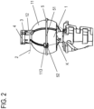
- Such a wire outlet slit 123 enables a wire end leaving the subsequently described wire tensioning body 3 to get to the outside through the wire outlet slit 123, as it is shown in Figure 2 .
- a first latching nose 124 for a subsequently described covering body, extending radially inwards is provided at the inner circumferential surface of the annular extension 12, wherein the covering body covers the control element 1 from the proximal side.
- a further radially inwardly extending latching nose (not shown) is also arranged on the inner circumferential surface of the annular extension 12 on the same level as the first latching nose 124 and offset by approx. 120° with respect to the first latching nose 124.
- the wire tensioning body 3 forms an annular body and is made of a plastic material, but can alternatively be made of a metal as well.
- the wire tensioning body 3 has an inner circumferential surface, an outer circumferential surface, a distal surface facing towards the tilting body 11 and a proximal surface facing away from the tilting body 11.
- through-openings 31 formed as pairs are provided in the axial direction as wire anchoring openings between the distal surface and the proximal surface.
- three pairs of through-openings 31 are provided, each pair being assigned to one wire, and thus, to one groove 111 of the tilting body 11.
- the respective pairs of through-openings 31 are arranged symmetrically and equally spaced apart on the wire tensioning body 3.
- the through-openings 31 are arranged radially offset from the inner circumferential surface and the outer circumferential surface of the wire tensioning body 3.
- the through-openings 31 belonging to a pair of through-openings 31 are spaced apart in the circumferential direction of the wire tensioning body 3.
- the distance of the through openings 31 belonging to a pair of through-openings 31 corresponds to the distance between the wire inlet slit 122 and the wire outlet slit 123 in the circumferential direction of the annular extension 12.
- the wire tensioning body 3 On the outer circumferential surface, the wire tensioning body 3 has axially extending protrusions 33 in a cuboid-like shape, as it is shown in Figure 1 .
- the protrusions 33 are also arranged symmetrically and equally spaced apart on the wire tensioning body 3.
- the protrusions 33 are provided between the notches 32, viewed in the circumferential direction of the wire tensioning body 3.
- the wire tensioning body 3 has an axially extending nose 34 on the inner circumferential surface.
- Three protrusions 33 are provided in the embodiment, but the invention is not restricted to a certain number of protrusions.
- the engagement member 4 is formed in an annular shape.
- the engagement member 4 is made of a plastic material but may alternatively also be made of a metal.
- the engagement member 4 has an inner circumferential surface, an outer circumferential surface, a distal surface facing towards the wire tensioning body 3 and a proximal surface facing away from the wire tensioning body 3.
- Locking pins 41 protruding in the axial direction and formed as pairs are provided on the distal surface.
- Each locking pin 41 is arranged on the distal surface of the engagement member 4 and dimensioned such that it can be inserted into one through-opening 31. Therefore, three pairs of locking pins 41 are provided in the embodiment, each of the pairs being assigned to one wire.
- the respective pairs of locking pins 41 are therefore arranged symmetrically and spaced apart by 120° on the engagement member 4.
- Bulges 42 protruding in the axial direction are provided on the distal surface of the engagement member 4, the bulges having a shorter axial length than the locking pins 41.
- three bulges 42 are provided of which only one bulge 42 is shown in Figure 1 .
- the bulges 42 are arranged symmetrically and equally spaced apart by 120° and offset on the engagement member 4.
- one bulge 42 is provided between each of the pairs of locking pins 41.
- the engagement member 4 On the outer circumferential surface the engagement member 4 has axially extending protrusions 43 in a cuboid-like shape.
- the protrusions 43 are also arranged symmetrically and equally spaced apart on the engagement member 4.
- the protrusions 43 are arranged on the engagement member 4 in a manner corresponding to the protrusions 33 of the wire tensioning body 3, cf. also Figure 2 .
- the engagement member 4 has an axially extending nose 44 on the inner circumferential surface.
- the wire tensioning body 3 being able to tension the wire 2
- the wire 2 has to be fixedly anchored, i.e. fixed in the wire tensioning body.
- Figure 3 shows the fixing of a wire
- Figure 3A showing an engagement member 4
- Figure 3B showing a wire tensioning body 3 with a wire 2
- Figure 3C showing how the wire tensioning body 3 and the engagement member 4 are assembled to fix the wire 2.
- the wire 2 is inserted in a first pair of through-openings 31 from the distal side of the wire tensioning body 3, passes through the first through-opening 31 in the proximal direction and is inserted into the second through-opening 31 on the proximal side of the wire tensioning body 3 and passes through the second through-opening 31 in the distal direction, as it is shown in Figure 3B.
- the engagement member 4 is arranged from the proximal side on the wire tensioning body 3 provided with the wire 2 so that the respective locking pin 41 is inserted into its corresponding through-opening 31, cf. Figure 3C.
- the locking pin 41 clamps the wire 2 positioned in its corresponding through-opening 31.
- the wire 2 is thus anchored to the wire tensioning body 3 and the engagement member 4 by means of a loop.
- a clamping of the wire 2 in the wire tensioning body 3 and the engagement member 4 already ensures a sufficient fixing of the wire 2.
- the wire 2 can also be fixed such that it is anchored in two or more loops to the wire tensioning body 3 and the engagement member 4. This means, after the wire 2 has left the second through-opening 31, it is again inserted into the first pair of through-openings 31 in the proximal direction, passes the same, and so on.
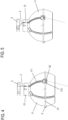
- a wire 2 is anchored in each pair of through-openings 31, wherein the engagement member 4 has been omitted in Figures 4 and 5 .
- the wire 2 is inserted in a first pair of through-openings 31 from the distal side of the wire tensioning body 3, passes through the first through-opening 31, and is inserted into the second through-opening 31 on the proximal side of the wire tensioning body 3 and passes through the second through-opening 31.
- a proximal end of the wire 2 is wound along the first through-opening 31, a portion of the proximal surface of the wire tensioning body 3, the second through-opening 31 and a portion of the distal surface of the wire tensioning body 3.
- the engagement member 4 is placed on the wire tensioning body 3.
- the respective locking pin 41 is inserted into its corresponding through-opening 31.
- the locking pin 41 clamps the wire 2 positioned in its corresponding through-hole 31.
- Figure 4 shows a position of the wire tensioning body 3 relative to the tilting body 11, where the anchored wire 2 is not tensioned. In this position, the distance between the wire insertion location on the distal surface of the wire tensioning body 3 and the wire exit location on the proximal surface of the annular extension 12 is minimal.
- a brake ring 5 is placed on the outer circumference of the distal tilting body 11. More precisely, the brake ring 5 is arranged in the equatorial area of the distal tilting body 11.
- the brake ring 5 is formed of an annular member 51 and a toggle lever element 52 integrally formed on the annular member 51.
- the toggle lever element 52 extends inwards from the annular member 51.
- the toggle lever element 52 does not extend inwards from the annular member 51 perpendicularly or vertically in the median plane of the annular member 51, but the extension direction of the toggle lever element 52 from the annular member 51 is at a predetermined angle to the median plane of the annular member 51.
- the end of the toggle lever element 52 facing away from the annular member 51 is seated in the opening 113 of the outer surface of the spherical body 11.
- the bottom of the blind-hole-like opening 113 forms an inner support surface for the toggle lever element 52.
- the annular member 51 is interrupted so as to let the wire 2 pass.
- the number of toggle lever elements 52 at the annular member 51 corresponds to the number of openings 113.
- the brake ring 5 can switch between two end positions.
- the first end position is the position in which it presses the spherical body 11 inwards against the counter ball portion (counter ball segment). This is the brake position in which a movement of the control element 1 relative to the counter ball portion is impeded by braking friction.
- the brake position has the purpose of locking a tilting position of the control element 1, achieved during the application of the endoscope, relative to the counter ball portion and, thus, a deflecting position of the tiltable deflecting member or deflecting portion.
- the second end position is the position where the brake ring 5 does not press the spherical body 11 inwards against the counter ball portion. This is the unbraked position, in which a movement of the control element 1 relative to the counter ball portion is possible.
- a hood member 6 is arranged on the outer side of the control element 1.
- Figure 6 shows the hood member from below, i.e., from the distal side.
- the hood member 6 surrounds the outer surface of the control element 1 and has a neck 61 on its proximal side and a spherical portion 63 on its distal side.
- a transition portion 62 is integrally arranged between the neck 61 and the spherical portion 63.
- the neck 61 is constructed as a hollow cylinder, the inner diameter of which is slightly larger than the outer diameter of the wire tensioning ring 3 and the engagement member 4.
- the guiding grooves 67 extend in the longitudinal direction of the neck 61.
- the guiding grooves 67 are arranged symmetrically and equally spaced apart on the inner circumference of the neck 61.
- Each of the guiding grooves 67 respectively accommodates one of the protrusions 33 of the wire tensioning ring 3 and one of the protrusions 43 of the engagement member 4. Therefore, the inner shape of the guiding grooves 67 is adapted to the outer shape of the protrusions 33 of the wire tensioning ring 3 and one of the protrusions 43 of the engagement member 4.
- the spherical portion 63 has a bell shape which is seated on the outer side of the distal tilting body 11.
- the spherical portion 63 is tiltable together with the distal tilting body 11, relative to the counter ball portion.
- the spherical portion 63 forms an outer shell that forms the bell shape and surrounds the distal tilting body 11.
- the spherical portion 63 is a partial spherical surface body having a constant wall thickness, as it is shown in Figure 8 .
- the spherical portion 63 has an inner circumferential surface and an outer circumferential surface.
- the inner circumferential surface of the spherical portion 63 faces toward the distal tilting body 11 and the outer circumferential surface of the spherical portion 63 faces away from the distal tilting body 11.
- the inner circumferential surface of the spherical portion 63 is spaced apart from the outer circumferential surface of the distal tilting body 11 by a predetermined distance.
- the hood member 6 On the inner circumferential surface of the spherical portion 63, the hood member 6 has an annular groove 64 on the equator.
- the annular body 51 of the brake ring 5 is inserted into the annular groove 64.
- the outer circumference of the annular body 51 of the brake ring 5 abuts against the inner circumference of the annular groove 64.
- the annular member 51 is placed in a tiltable manner in the annular groove 64 of the inner surface of the spherical portion 63, said annular groove being adapted to the annular shape of the annular member 51, cf. Figure 8 .
- the annular groove 64 forms the outer support surface of the toggle lever element 52.
- the spherical portion 63 can be displaced relative to the distal tiltable body 11, by the neck 61 sliding along the outer circumference of the proximal annular extension.
- the spherical portion 63 is displaced along the axis of the control element 1, relative to the distal tilting body 11, two intrinsically stable end positions are formed.
- the brake position is established as first end position, cf. Figure 8 .
- the unbraked position is established as second end position.
- the wire tensioning ring 3 and the engagement member 4 form an assembly.
- This assembly has the protrusions 33 and 43 and is placed in the neck 61 of the hood member 6.
- protrusions 33 and 43 placed in the guiding grooves 67 of the neck 61 and, thus, the assembly consisting of the wire tensioning body 3 and the engagement member 4 are rotated by (clockwise) rotation of the hood member 6, more explicitly the neck 61, so as to tension the wires 2.
- the neck 61 thus forms a rotating member for tensioning the wires 2.
- a funnel member 7 is engagingly set from the proximal side of the neck 61 into the neck 61 of the hood member 6, cf. Figure 7 .
- the funnel member 7 prevents the wire tensioning ring 3 and the engagement member 4 from slipping out.
- the funnel member 7 has a tapering funnel entrance opening 71 through which a catheter (entering tube) can be inserted from the proximal side.
- the funnel entrance opening 71 passes into a through-opening which is adapted to pass on the inserted catheter.
- the funnel member 7 comprises a proximal portion 72 having a constantly large diameter, a distal portion 74 having a constantly small diameter, and an intermediate portion 73 having a tapering diameter integrally connecting the proximal portion 72 to the distal portion 74.
- the distal portion 74 comprises the through-opening for the catheter.
- the funnel member 7 acts as covering body and, on the inserted outer circumference of the distal portion 74, comprises a notch 75 with which the latching nose 124 of the annular extension 12 can engage.
- two notches 75 offset by approximately 120° are formed on the outer circumference of the distal portion 74. These two notches 75 are orientated such that they can lock with the two latching noses 124 of the annular extension 12, which are offset by approximately 120°.
- the funnel member 7 On the distal portion 74 of its outer circumference, the funnel member 7 has several engagement grooves 76, 77 and 78 on the same level. To be more precise, the engagement grooves 76, 77 and 78 are in the area of the section of line A-A in Figure 7A.
- Figure 7B shows the distal portion 74 in a view from the bottom, the area of the engagement grooves 76, 77 and 78 being visible.
- Figure 7C shows the section of line A-A of Figure 7A in a view from the top.
- the engagement grooves 76, 77 and 78 are constructed such that the nose 34 on the inner peripheral surface of the wire tensioning body 3 is adapted to engage in the engagement grooves 76, 77 and 78, respectively. More exactly, the construction is selected such that, in the engagement grooves 76, 77 and 78, at least one of the (or both) noses 34, 44 of the assembly composed of the wire tensioning body 3 and the engagement member 4 can engage.
- the engagement grooves 76, 77 and 78 have specific shapes.
- the first engagement groove 76 On the edge being in the counter-clockwise direction in the top view of Figure 7C , the first engagement groove 76 has a step to the outer circumference of the distal portion 74. By contrast, the transition of the first engagement groove 76 towards the edge being in the clockwise direction is flattened. The first engagement groove 76 forms a start groove.
- the nose/s 34 and/or 44 are/is engaged in the first engagement groove 76 when the wires 2 are not yet tensioned. Due to the specific design of the edges of the first engagement groove 76, the assembly of wire tensioning body 3 and engagement member 4 can be slightly moved out of the first engagement groove 76 in the clockwise direction, but cannot be moved in the counter-clockwise direction.
- the second engagement groove 77 also has a step to the outer circumference of the distal portion 74 on the edge being in the counter-clockwise direction, and has a flattened edge to the outer circumference of the distal portion 74 in the clockwise direction.
- the second engagement groove 77 forms an intermediate groove.
- the wires 2 can be (pre-)tensioned to an intermediate position by the assembly of wire tensioning body 3 and engagement member 4 being turned from the first engagement groove 76 to the second engagement groove 77 and engaging there.
- the wires 2 cannot be slackened (released) again from the second engagement groove 77 because, due to the step to the outer circumference of the distal portion 74, the assembly of wire tensioning body 3 and engagement member 4 cannot be turned in the counter-clockwise direction (i.e. not backwards). That is, the assembly of wire tensioning body 3 and engagement member 4 cannot be turned back from the second engagement groove 77 to the first engagement groove 76.
- the third engagement groove 78 has a step to the outer circumference of the distal portion 74 on the edge located in the counter-clockwise direction and on the edge located in the clockwise direction.
- the third engagement groove 78 forms an end groove.
- the wires 2 can be tensioned from the intermediate position to the end position by the assembly of wire tensioning body 3 and engagement member 4 being turned from the second engagement groove 77 to the third engagement groove 78 and engaging there.
- the wires 2 cannot be released again from the third engagement groove 78 because, due to the step to the outer circumference of the distal portion 74, the assembly of wire tensioning body 3 and engagement member 4 cannot be turned in the counter-clockwise direction (i.e. not backwards). Thus, the assembly of wire tensioning body 3 and engagement member 4 cannot be turned back from the third engagement groove 78 to the second engagement groove 77.
- the engagement grooves 76, 77 and 78 are arranged on the outer circumference of the distal portion 74 above the notch 75. In other terms, the engagement grooves 76, 77 and 78 are proximal relative to the notch 75.
- the funnel member 7 is provided with direction markers 79 which indicate the tilting directions of the control element 1 to the user, cf. Figure 7 .
- the predefined positional relation between the notches 75 on the distal portion of the funnel member 7 and the latching noses 124 of the annular extension 12 serves to ensure the correct orientation of the direction markers 79.
- the tilting body 11 of the control element 1 including its annular extension 12 is provided.
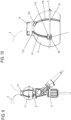
- the tilting body 11 is flexible and, due to its incisions 115, it can be bent open and placed onto a prepared counter-ball portion (counter-ball segment) of an endoscope E, cf. Figure 9 .
- the counter-ball portion is hinted at; there, the counter-ball portion is shown to slightly project on the distal side of the tilting body 11.
- this counter-ball portion is formed such that the tilting body 11 can swivel/pivot thereon as desired.
- the exact construction of the counter-ball portion shall not be subject to any restrictions.
- Figure 10 shows an enlargement of the representation of the tilting body 11 as shown in Figure 9 . It has to be noted that Figure 10 shows the brake position. From this position, the brake ring 5 can be moved to the unbraked position in the direction shown by the arrow.
- the wire 2 is inserted into the deflecting element (deflecting portion) on the distal end of the endoscope and is guided through the endoscope. Then, the wire 2 is guided at the outer side of the tilting body 11 from the distal side over the distal opening 113 by the toggle lever element 52 into the bottomed groove; further, the wire 2 is guided along the groove 111 from the outside through the proximal opening 112 to the inner circumferential side of the tilting body 11. Finally, the wire 2 projects from the annular extension 12, cf. Figure 10 . It can be seen in Figure 10 that three prepared wires 2 project from the annular extension 12.
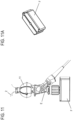
- the endoscope is fixed by means of a fixation F, cf. Figure 11.
- Figure 11A shows the fixation F in more detail.
- the fixation F is a device for holding the endoscope, i.e. the basic endoscope E for the purpose of assembly.
- the fixation F comprises two clamping jaws, which are rotatable to each other and between which the basic endoscope E is held.
- every holding device adapted to maintain the basic endoscope E fixed is suited.
- the wire 2 is held by hand and an assembly pin D is axially inserted from the proximal side into the annular extension 12, cf. Figure 12 .
- the assembly pin D is shown in Figure 13 .
- the assembly pin D is constructed as a solid cylindrical pin and is provided with a smaller-diameter portion and a larger-diameter portion. A stop is formed between the smaller-diameter portion and the larger-diameter portion.
- the assembly pin D comprises a slot extending in the axial direction, said slot extending over the smaller-diameter portion and the larger-diameter portion, as is shown in Figure 13 . To be more exact, the smaller-diameter portion of the assembly pin D is being inserted into the annular extension 12 up to the stop.
- the wire tensioning body 3 is mounted onto the assembly pin D such that the inner circumferential surface of the wire tensioning body 3 can slide on the outer circumferential surface of the assembly pin D and the nose 34 is guided in the slot of the assembly pin D.
- the engagement member 4 is mounted onto the assembly pin D such that the inner circumferential surface of the engagement member 4 can slide on the outer circumferential surface of the assembly pin D and the nose 44 is guided in the slot of the assembly pin D, cf. Figure 15 .
- the noses 43 and 44 already determine the correct relative positions of the wire tensioning body 3 and the engagement member 4.
- the wire 2 is wound on the wire tensioning body 3 in the manner described under "fixing of the wire 2". That is to say, the wire 2 is inserted from the distal side of the wire tensioning body 3 into the first through-opening 31, passes through the first through-opening 31 in the proximal direction, and is inserted into the second through-opening 31 on the proximal side of the wire tensioning body 3, and passes through the second through-opening 31 in the distal direction, as is shown by Figure 16 .
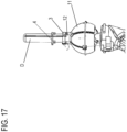
- the wire 2 is sufficiently tensioned, with the wire tensioning body 3 being placed on the proximal surface of the annular extension 12, cf. Figure 17 .
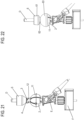
- an adhesive is applied onto the proximal surface of the wire tensioning body 3 and the engagement member 4 is pushed to the proximal surface of the wire tensioning body 3 by means of a slider S by the respective locking pins 41 being inserted into the corresponding through-openings 31 and the noses 42 penetrating into the notches 32, cf. Figure 18 .
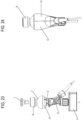
- the slider S is shown more clearly in Figure 19 .
- the slider S is a hollow cylinder which is provided with a tapering and which is adapted to slide on the assembly pin D and having, on the tapering, a surface by which the slider S pushes the engagement member 4 to the wire tensioning body 3, cf. Figure 20 .
- the slider S is removed and, in its stead, the hood member 6 is placed on the proximal side of the control element 1 with its spherical portion 63 up front such that the protrusions 33, 43 of the engagement member 4 and the wire tensioning body 3 are arranged in the guiding groove 67 and the annular member 51 is seated in the annular groove 64, cf. Figure 22 .
- control element 1 is completed.
- the control element 1 is ready for tensioning the wires 2.
- the intermediate groove 77 can be used to achieve a momentary work tension of the wires 2. Should, after a certain period of time, the tension of the wires have slackened and not be sufficient any more despite the engagement of the assembly of wire tensioning ring 3 and engagement member 4 in the intermediate groove 77, the assembly of wire tensioning ring 3 and engagement member 4 can be turned on from the intermediate groove 77 to the end groove 78 and engage therein so as to again achieve a suitable wire tension.
- the tensioning of the wires is realized by a rotational movement taking place about the longitudinal axis of the hood member 6.
- the temporary locking of the wires by the brake ring 5 is realized by a sliding movement taking place in the axial direction (a translational motion) of the hood member 6.
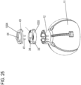
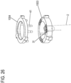
- the second embodiment differs from the first embodiment such that the wire tensioning body 1003 does not have any notches and the engagement member 1004 does not have any noses, cf. Figures 25 and 26 .
- the wire 2 is inserted from the distal side of the wire tensioning body 1003 into the first one of a pair of through-openings 31, passes through the first through-opening 31 in the proximal direction, is inserted into the second through-opening 31 at the proximal side of the wire tensioning body 1003, and passes through the second through-opening 31 in the distal direction.
- the second embodiment is equal to the first embodiment.
- the third embodiment differs from the first embodiment in that the individual wires 2, 2A are adapted to be tensioned differently whereas all wires 2 of the first embodiment are evenly tensioned. As for the rest, the third embodiment is equal to the first embodiment.
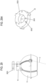
- a distal tilting body 2011 with its proximal annular extension 2012 is combined with a wire tensioning body 2003 such that a first wire 2 is perpendicularly arranged from the wire tensioning body 2003 to the annular extension 2012 while a second wire 2A is arranged obliquely from the wire tensioning body 2003 to the annular extension 2012.
- the second wire 2A obliquely runs from the annular extension 2012 to a through-opening 31, which is arranged closer to the through-openings 31 for the first wire.
- the tensionable path distance of the first wire 2 is shorter than that of the second wire 2A.
- the wires 2, 2A are tensioned by turning the wire tensioning body 2003 from the position shown in Figure 27 such (to the left) that the first wire 2 is tensioned by the wire tensioning body 2003 to the left, while the second wire 2A is first released to the left and is then, upon further turning of the wire tensioning body 2003, also tensioned to the left; it is, however, tensioned less strongly than the first wire 2, cf. Figure 28 .
- Differently tensioned wires entail the following advantage.
- the introductory tube (catheter) of the endoscope in its resting state or also when applied is usually wound twice or several times about its own axis
- the wires in the endoscope are exposed to different tensions. Therefore, in most cases, one wire is tensioned more strongly than the other wires.
- the control element (joystick) is already tilted in its start position in a direction in which it is pulled by the more strongly tensioned wire.
- the present embodiment provides a solution according to which, despite the winding about its own axis, the endoscope is applicable such that the control element (joystick) in its inoperative state is in the vertical neutral position. This makes it easier to use the endoscope. The user no longer has to consider pretensionings of the wire caused by winding about its own axis or, at least, he has to consider these less.
- wires are tensioned differently due to having differently long tensionable distances between the annular extension and the wire tensioning body.
- wires are tensioned differently by using an inner through-opening 3031 and an outer through-opening 3032 on the wire tensioning body 3003. The distance of the inner through-opening 3031 to the center of the wire tensioning body 3003 is less than the distance of the outer through-opening 3032 to the center of the wire tensioning body 3003.
- One wire 2 is inserted into the inner through-opening 3031 and into the outer through-opening 3032, respectively, is guided to the inner circumference of the wire tensioning body 3003, is guided in the distal direction and is, in the distal direction, again inserted into the respective inner through-opening 3031 or outer through-opening 3032; thus, every wire forms a whole loop.
- one wire 2 is inserted into the inner through-opening 3031 and into the outer through-opening 3032, respectively, and is clamped therein by one locking pin of the engagement member, respectively, without forming a loop.
- the wire tensioning body 3003 is turned clockwise from the position shown in Figure 29 , the wire clamped in the inner through-opening 3031 being tensioned less strongly than the wire clamped in the outer through-opening 3032.
- three wires 2 are provided as pulling cables.
- the number of wires 2 is not limited here. One wire, 2, 3, 4 or more wires can be provided. If two or more wires 2 are provided, the respective grooves 111 are arranged at even distances to each other, perpendicularly to the equator of the tilting body 11.
- the wire 2 is only clamped on the wire tensioning body 3 by the wire 2 being guided through the through-openings 31 and the respective locking pin 41 being inserted into its pertinent through-opening 31.
- the locking pin 41 clamps the wire 2, which is located in its pertinent through-opening 31.
- the wire 2 can alternatively or additionally be inserted from the distal side of the wire tensioning body 3 into a first one of the pair of through-openings 31, pass through the first through-opening 31, and be inserted into the second through-opening 31 on the proximal side of the wire tensioning member 3, pass through the second through-opening 31, and then be linked to the portion of the wire 2 on the distal side of the wire tensioning member 3.
- the wire 2 can comprise a crimped portion which is e.g. arranged below the second through-opening 31 and is deformed such that the deformed crimped portion cannot pass through the through-opening 31 blocked by the locking pin 41.
- the wire 2 can be pulled by hand for the assembly. So as to increase the mounting precision, a wire-pulling means can be used for pulling and tensioning the wire 2 at an adjustable force.
- the wire 2 can be pulled at 2 Newton.
- the wire 2 can be pulled at 3 Newton. Of course, these are only examples. Other forces may be applied.
- the adhesive agent which is applied onto the proximal surface of the wire tensioning body 3 when the engagement member 4 and the wire tensioning body 3 are assembled, may be omitted.
- the annular extension 12 is provided with two latching noses 124 displaced by 120° and adapted to engage in the respective notches 75 displaced by 120° and formed on the distal portion of the funnel member 7.
- the annular extension 12 can be provided with only one latching nose 124 adapted to engage in one single notch 75 formed on the distal portion of the funnel member 7.
- the annular extension 12 can be provided with three or more latching noses that are adapted to engage with respective three or more notches 75 formed on the distal portion of the funnel member 7.
- two latching noses 124 are provided, these can also be arranged to be diagonally opposite to each other. Analogously, then, two notches are formed diagonally opposite on the distal portion of the funnel member 7.
- the second engagement groove 77 as intermediate groove can have a flattened edge to the outer circumference of the distal portion 74 in the counter-clockwise direction and in the clockwise direction.
- the second engagement groove 77 can allow a reversible engaging of the assembly of wire tensioning body 3 and engagement member 4.
- wires 2 can be tensioned by the assembly of wire tensioning body 3 and engagement member 4 being turned from the first engagement groove 76 to the second engagement groove 77 and engaging there.
- the wires 2 can be slackened (released) again by the assembly of wire tensioning body 3 and engagement member 4 being turned from the second engagement groove 77 to the first engagement groove 76 and engaging there.
- the second engagement groove 77 can be omitted.
- the wires 2 can only be tensioned by engagement in the third engagement groove 78.
- the second engagement groove 77 and/or the third engagement groove 78 can also have, instead of the step, a flattened edge to the outer circumference of the distal portion 74 in the counter-clockwise direction as well.
- a control element constructed in this way allows a reversible engagement of the assembly of wire tensioning body 3 and engagement member 4 in the second engagement groove 77 and/or third engagement groove 78.
- the wires can be tensioned and, if required, again be slackened by the user.
- the wire guiding groove 111 is designated as wire guiding means.
- the wire guiding means is not restricted to the groove 111 and comprises any member on the control element 1 which serves to guide the wire 2.
- another possibility could be a modification according to which the groove 111 is omitted and the wire 2 is only guided in the proximal annular extension 12.
Landscapes
- Health & Medical Sciences (AREA)
- Life Sciences & Earth Sciences (AREA)
- Surgery (AREA)
- Biomedical Technology (AREA)
- Medical Informatics (AREA)
- Optics & Photonics (AREA)
- Pathology (AREA)
- Radiology & Medical Imaging (AREA)
- Biophysics (AREA)
- Engineering & Computer Science (AREA)
- Physics & Mathematics (AREA)
- Heart & Thoracic Surgery (AREA)
- Nuclear Medicine, Radiotherapy & Molecular Imaging (AREA)
- Molecular Biology (AREA)
- Animal Behavior & Ethology (AREA)
- General Health & Medical Sciences (AREA)
- Public Health (AREA)
- Veterinary Medicine (AREA)
- Instruments For Viewing The Inside Of Hollow Bodies (AREA)
- Endoscopes (AREA)
Claims (7)
- Endoskopsteuervorrichtung für ein nichtstarres Endoskop miteinem schwenkbaren Steuerelement (1, 11) zum Bewirken einer Auslenkbewegung mittels Übertragungsdraht, wobei das Steuerelement (1, 11) eine Drahtführungseinrichtung (111, 122) zur Führung eines Drahtes (2) aufweist;dem Draht (2), der an dem Steuerelement (1, 11) an der Drahtführungseinrichtung (111, 122) zur Verwirklichung der Auslenkbewegung angeordnet ist; undeinem Drahtspannkörper (3), in dem ein proximales Ende des Drahtes (2) verankert ist und der relativ zum Steuerelement (1, 11) bewegbar ist, um die Spannung des Drahtes (2) zwischen der Drahtführungseinrichtung (111, 122) und dem Drahtspannkörper (3) zu ändern,
dadurch gekennzeichnet, dassder Drahtspannkörper (3) daran angepasst ist, dass er relativ zu dem Steuerelement (1, 11) so drehbar ist, dass ein Abstand des Drahtes (2) zwischen einem Drahtverankerungsort in dem Drahtspannkörper (3) und der Drahtführungseinrichtung (111, 122) so veränderbar ist, dass eine vordefinierte Spannung auf den Draht (2) aufgebracht werden kann. - Endoskopsteuervorrichtung gemäß Anspruch 1, wobei
der Drahtspannkörper (3) an der proximalen Seite des Steuerelementes (1, 11) angeordnet ist. - Endoskopsteuervorrichtung gemäß einem der Ansprüche 1 oder 2, wobei
der Drahtspannkörper (3) ein Ringkörper ist, der Drahtverankerungsöffnungen (31) hat, in denen der Draht (2) sitzt, wobei der Ringkörper zum Spannen des Drahtes (2) relativ zum Steuerelement (1, 11) drehbar ist. - Endoskopsteuervorrichtung gemäß einem der Ansprüche 1 bis 3, wobei
im Drahtspannkörper (3) in Drahtverankerungsöffnungen (31) zumindest zwei Drähte (2) so verankert sind, dass die zumindest zwei Drähte (2) zueinander unterschiedlich lange spannbare Längen zwischen ihrem jeweiligen Verankerungsort am Drahtspannkörper (3) und ihrer jeweiligen Drahtführungseinrichtung (111, 122) des Steuerelementes (1, 11) haben, wobei während einer Relativbewegung des Drahtspannkörpers (3) zur Drahtführungseinrichtung (111, 122) des Steuerelementes (1, 11) die zumindest zwei verankerten Drähte (2) um zueinander unterschiedliche Längenänderungen spannbar sind. - Endoskopsteuervorrichtung gemäß einem der Ansprüche 1 bis 4, die des Weiteren ein Fixierelement (5) zum vorübergehenden Fixieren des Drahtes (2) unabhängig vom Drahtspannkörper (3) aufweist.
- Endoskopsteuervorrichtung gemäß einem der Ansprüche 1 bis 4, wobei das schwenkbare Steuerelement (1, 11) ein Steuerelement (1, 11) der Joystickart ist.
- Endoskop mit einer Endoskopsteuervorrichtung gemäß einem der Ansprüche 1 bis 6.
Applications Claiming Priority (2)
| Application Number | Priority Date | Filing Date | Title |
|---|---|---|---|
| DE102016105767.3A DE102016105767B4 (de) | 2016-03-30 | 2016-03-30 | Endoskopsteuervorrichtung und Endoskop |
| PCT/EP2017/057249 WO2017167713A1 (en) | 2016-03-30 | 2017-03-28 | Endoscope control device and endoscope |
Publications (3)
| Publication Number | Publication Date |
|---|---|
| EP3435835A1 EP3435835A1 (de) | 2019-02-06 |
| EP3435835B1 true EP3435835B1 (de) | 2025-03-05 |
| EP3435835C0 EP3435835C0 (de) | 2025-03-05 |
Family
ID=58428284
Family Applications (1)
| Application Number | Title | Priority Date | Filing Date |
|---|---|---|---|
| EP17713941.7A Active EP3435835B1 (de) | 2016-03-30 | 2017-03-28 | Endoskopsteuerungsvorrichtung und endoskop |
Country Status (7)
| Country | Link |
|---|---|
| US (1) | US11083363B2 (de) |
| EP (1) | EP3435835B1 (de) |
| JP (1) | JP6661788B2 (de) |
| CN (1) | CN109068957B (de) |
| DE (1) | DE102016105767B4 (de) |
| ES (1) | ES3026137T3 (de) |
| WO (1) | WO2017167713A1 (de) |
Families Citing this family (17)
| Publication number | Priority date | Publication date | Assignee | Title |
|---|---|---|---|---|
| DE102016121056A1 (de) | 2016-11-04 | 2018-05-09 | Digital Endoscopy Gmbh | Arbeitskanalelement, endoskop mit einem arbeitskanalelement, und verfahren zur anwendung eines arbeitskanals in einem endoskop |
| JP7048628B2 (ja) | 2016-11-28 | 2022-04-05 | アダプティブエンドウ エルエルシー | 分離可能使い捨てシャフト付き内視鏡 |
| CN110234263B (zh) | 2017-03-08 | 2022-04-08 | 安布股份有限公司 | 用于内窥镜的手柄 |
| US11642014B2 (en) | 2017-03-08 | 2023-05-09 | Ambu A/S | Handle for an endoscope |
| CN111200962A (zh) * | 2017-10-11 | 2020-05-26 | 奥林巴斯株式会社 | 内窥镜用操作线牵拉装置 |
| EP3513706B1 (de) | 2018-01-19 | 2024-10-16 | Ambu A/S | Verfahren zur befestigung eines drahtteils eines endoskops sowie endoskop |
| EP3517017B1 (de) * | 2018-01-26 | 2023-01-18 | Ambu A/S | Verfahren zur fixierung eines drahtabschnitts eines endoskops sowie ein endoskop |
| USD1018844S1 (en) | 2020-01-09 | 2024-03-19 | Adaptivendo Llc | Endoscope handle |
| DE102020122281A1 (de) | 2020-08-26 | 2022-03-03 | Hoya Corporation | Endoskopsteuervorrichtung mit Steuerelement und Zugseil |
| USD1051380S1 (en) | 2020-11-17 | 2024-11-12 | Adaptivendo Llc | Endoscope handle |
| WO2022185116A1 (en) * | 2021-03-05 | 2022-09-09 | Endovista, Inc. | Control device and rotary knob assembly for a steerable medical device |
| USD1031035S1 (en) | 2021-04-29 | 2024-06-11 | Adaptivendo Llc | Endoscope handle |
| USD1070082S1 (en) | 2021-04-29 | 2025-04-08 | Adaptivendo Llc | Endoscope handle |
| USD1066659S1 (en) | 2021-09-24 | 2025-03-11 | Adaptivendo Llc | Endoscope handle |
| CN114711953B (zh) * | 2022-04-29 | 2023-03-10 | 江苏唯德康医疗科技有限公司 | 一种内窥镜下手术器械 |
| US20240115118A1 (en) * | 2022-10-05 | 2024-04-11 | Gyrus Acmi, Inc. D/B/A Olympus Surgical Technologies America | Pull wire tensioning mechanisms for endoscopes |
| CN117958727B (zh) * | 2024-03-01 | 2024-09-24 | 深圳知微医疗设备有限公司 | 一种内窥镜钢索张紧力调节机构及内窥镜 |
Citations (1)
| Publication number | Priority date | Publication date | Assignee | Title |
|---|---|---|---|---|
| EP2151204A1 (de) * | 2008-08-04 | 2010-02-10 | Tyco Healthcare Group LP | Bewegliche chirurgische Vorrichtung |
Family Cites Families (17)
| Publication number | Priority date | Publication date | Assignee | Title |
|---|---|---|---|---|
| US3892228A (en) | 1972-10-06 | 1975-07-01 | Olympus Optical Co | Apparatus for adjusting the flexing of the bending section of an endoscope |
| US4941454A (en) * | 1989-10-05 | 1990-07-17 | Welch Allyn, Inc. | Servo actuated steering mechanism for borescope or endoscope |
| US5960145A (en) * | 1997-01-21 | 1999-09-28 | Sanchez; Jorge O. | Optical fiber image conduit and method using same |
| US6440062B1 (en) | 1999-11-10 | 2002-08-27 | Asahi Kogaku Kogyo Kabushiki Kaisha | Control wire driving mechanism for use in endoscope |
| EP1886617A4 (de) | 2005-05-26 | 2010-09-29 | Ars Co Ltd | Endoskopvorrichtung |
| US8409175B2 (en) | 2005-07-20 | 2013-04-02 | Woojin Lee | Surgical instrument guide device |
| US20070225562A1 (en) * | 2006-03-23 | 2007-09-27 | Ethicon Endo-Surgery, Inc. | Articulating endoscopic accessory channel |
| US7862554B2 (en) * | 2007-04-16 | 2011-01-04 | Intuitive Surgical Operations, Inc. | Articulating tool with improved tension member system |
| JP5161529B2 (ja) * | 2007-10-10 | 2013-03-13 | 株式会社アールエフ | 内視鏡 |
| US8641604B2 (en) * | 2008-05-13 | 2014-02-04 | Boston Scientific Scimed, Inc. | Steering system with locking mechanism |
| WO2011075512A2 (en) * | 2009-12-18 | 2011-06-23 | Wilson-Cook Medical Inc. | Endoscope sheath |
| JP5851118B2 (ja) * | 2011-05-25 | 2016-02-03 | オリンパス株式会社 | 内視鏡装置 |
| EP2740397B1 (de) | 2011-08-03 | 2017-09-27 | Olympus Corporation | Drahtzugmechanismus und endoskopische vorrichtung |
| DE102013222041A1 (de) | 2013-10-30 | 2015-04-30 | Digital Endoscopy Gmbh | Auslenkbewegungsübertragungseinrichtung, Endoskopdeflectingsteuerung und Endoskop |
| WO2015118705A1 (ja) * | 2014-02-07 | 2015-08-13 | オリンパス株式会社 | 内視鏡 |
| CN106455939B (zh) * | 2014-06-20 | 2021-11-09 | 库克医学技术有限责任公司 | 小型驱动线保持在线轴上的机构 |
| DE102015109170B4 (de) | 2015-06-10 | 2019-08-22 | Digital Endoscopy Gmbh | Auslenkbewegungsübertragungseinrichtung, Endoskopbiegesteuereinrichtung und Endoskop |
-
2016
- 2016-03-30 DE DE102016105767.3A patent/DE102016105767B4/de active Active
-
2017
- 2017-03-28 JP JP2018550688A patent/JP6661788B2/ja active Active
- 2017-03-28 CN CN201780020231.0A patent/CN109068957B/zh active Active
- 2017-03-28 WO PCT/EP2017/057249 patent/WO2017167713A1/en not_active Ceased
- 2017-03-28 EP EP17713941.7A patent/EP3435835B1/de active Active
- 2017-03-28 ES ES17713941T patent/ES3026137T3/es active Active
- 2017-03-28 US US16/089,690 patent/US11083363B2/en active Active
Patent Citations (1)
| Publication number | Priority date | Publication date | Assignee | Title |
|---|---|---|---|---|
| EP2151204A1 (de) * | 2008-08-04 | 2010-02-10 | Tyco Healthcare Group LP | Bewegliche chirurgische Vorrichtung |
Also Published As
| Publication number | Publication date |
|---|---|
| EP3435835A1 (de) | 2019-02-06 |
| WO2017167713A1 (en) | 2017-10-05 |
| DE102016105767A1 (de) | 2017-10-05 |
| ES3026137T3 (en) | 2025-06-10 |
| US20190110661A1 (en) | 2019-04-18 |
| EP3435835C0 (de) | 2025-03-05 |
| US11083363B2 (en) | 2021-08-10 |
| CN109068957B (zh) | 2021-05-07 |
| CN109068957A (zh) | 2018-12-21 |
| JP6661788B2 (ja) | 2020-03-11 |
| DE102016105767B4 (de) | 2020-10-01 |
| JP2019511302A (ja) | 2019-04-25 |
Similar Documents
| Publication | Publication Date | Title |
|---|---|---|
| US11083363B2 (en) | Endoscope control device and endoscope | |
| CN110234263B (zh) | 用于内窥镜的手柄 | |
| US12201267B2 (en) | Endoscope control handle with a steering assembly | |
| US6464711B1 (en) | Articulating mechanism for steerable surgical cutting instruments | |
| CN100493464C (zh) | 用于内窥镜的插入装置 | |
| EP2967613B1 (de) | Griffe für eine medizinische vorrichtung | |
| US8308659B2 (en) | Bi-directional sheath deflection mechanism | |
| EP3120791B1 (de) | Polyaxiale knochenverankerungsvorrichtung und instrument zur verwendung damit | |
| US20090259105A1 (en) | Medical treatment system and suturing method | |
| US20150165162A1 (en) | Control mechanism for steerable medical device | |
| WO2001001871A1 (en) | Cannula with coupling interface | |
| CN119235226A (zh) | 用于内窥镜的手柄 | |
| US9993141B2 (en) | Control system for medical devices and related methods of use | |
| US20210315584A1 (en) | Ligation device, applicator, and connection method | |
| CN118750729B (zh) | 可调弯鞘 | |
| US20090223028A1 (en) | Magazine type clipping device | |
| JP4240185B2 (ja) | シールド板を有する気管切開用カニューレ | |
| US20040144630A1 (en) | Switching device | |
| US20240008896A1 (en) | Expandable surgical access port | |
| CN115279307B (zh) | 支架输送系统和用于支架输送系统的处理装置 | |
| JP2006153257A (ja) | コントロールケーブルの長さ調整装置 | |
| JP4046978B2 (ja) | 内視鏡用クリップ装置 | |
| JP4295994B2 (ja) | 側方視型内視鏡の先端部 | |
| EP4541256A2 (de) | Steuerungsmechanismen für bewegliche medizinische vorrichtungen | |
| EP4686453A1 (de) | Aufnahmeteil einer knochenverankerungsvorrichtung und system aus mindestens einem instrument und einem aufnahmeteil |
Legal Events
| Date | Code | Title | Description |
|---|---|---|---|
| STAA | Information on the status of an ep patent application or granted ep patent |
Free format text: STATUS: UNKNOWN |
|
| STAA | Information on the status of an ep patent application or granted ep patent |
Free format text: STATUS: THE INTERNATIONAL PUBLICATION HAS BEEN MADE |
|
| PUAI | Public reference made under article 153(3) epc to a published international application that has entered the european phase |
Free format text: ORIGINAL CODE: 0009012 |
|
| STAA | Information on the status of an ep patent application or granted ep patent |
Free format text: STATUS: REQUEST FOR EXAMINATION WAS MADE |
|
| 17P | Request for examination filed |
Effective date: 20180904 |
|
| AK | Designated contracting states |
Kind code of ref document: A1 Designated state(s): AL AT BE BG CH CY CZ DE DK EE ES FI FR GB GR HR HU IE IS IT LI LT LU LV MC MK MT NL NO PL PT RO RS SE SI SK SM TR |
|
| AX | Request for extension of the european patent |
Extension state: BA ME |
|
| DAV | Request for validation of the european patent (deleted) | ||
| DAX | Request for extension of the european patent (deleted) | ||
| STAA | Information on the status of an ep patent application or granted ep patent |
Free format text: STATUS: EXAMINATION IS IN PROGRESS |
|
| 17Q | First examination report despatched |
Effective date: 20220221 |
|
| GRAP | Despatch of communication of intention to grant a patent |
Free format text: ORIGINAL CODE: EPIDOSNIGR1 |
|
| STAA | Information on the status of an ep patent application or granted ep patent |
Free format text: STATUS: GRANT OF PATENT IS INTENDED |
|
| INTG | Intention to grant announced |
Effective date: 20241126 |
|
| GRAS | Grant fee paid |
Free format text: ORIGINAL CODE: EPIDOSNIGR3 |
|
| GRAA | (expected) grant |
Free format text: ORIGINAL CODE: 0009210 |
|
| STAA | Information on the status of an ep patent application or granted ep patent |
Free format text: STATUS: THE PATENT HAS BEEN GRANTED |
|
| AK | Designated contracting states |
Kind code of ref document: B1 Designated state(s): AL AT BE BG CH CY CZ DE DK EE ES FI FR GB GR HR HU IE IS IT LI LT LU LV MC MK MT NL NO PL PT RO RS SE SI SK SM TR |
|
| REG | Reference to a national code |
Ref country code: GB Ref legal event code: FG4D |
|
| REG | Reference to a national code |
Ref country code: CH Ref legal event code: EP |
|
| REG | Reference to a national code |
Ref country code: IE Ref legal event code: FG4D |
|
| REG | Reference to a national code |
Ref country code: DE Ref legal event code: R096 Ref document number: 602017088151 Country of ref document: DE |
|
| U01 | Request for unitary effect filed |
Effective date: 20250307 |
|
| U07 | Unitary effect registered |
Designated state(s): AT BE BG DE DK EE FI FR IT LT LU LV MT NL PT RO SE SI Effective date: 20250314 |
|
| U20 | Renewal fee for the european patent with unitary effect paid |
Year of fee payment: 9 Effective date: 20250424 |
|
| REG | Reference to a national code |
Ref country code: ES Ref legal event code: FG2A Ref document number: 3026137 Country of ref document: ES Kind code of ref document: T3 Effective date: 20250610 |
|
| PG25 | Lapsed in a contracting state [announced via postgrant information from national office to epo] |
Ref country code: RS Free format text: LAPSE BECAUSE OF FAILURE TO SUBMIT A TRANSLATION OF THE DESCRIPTION OR TO PAY THE FEE WITHIN THE PRESCRIBED TIME-LIMIT Effective date: 20250605 |
|
| PGFP | Annual fee paid to national office [announced via postgrant information from national office to epo] |
Ref country code: ES Payment date: 20250428 Year of fee payment: 9 |
|
| PG25 | Lapsed in a contracting state [announced via postgrant information from national office to epo] |
Ref country code: NO Free format text: LAPSE BECAUSE OF FAILURE TO SUBMIT A TRANSLATION OF THE DESCRIPTION OR TO PAY THE FEE WITHIN THE PRESCRIBED TIME-LIMIT Effective date: 20250605 |
|
| PG25 | Lapsed in a contracting state [announced via postgrant information from national office to epo] |
Ref country code: HR Free format text: LAPSE BECAUSE OF FAILURE TO SUBMIT A TRANSLATION OF THE DESCRIPTION OR TO PAY THE FEE WITHIN THE PRESCRIBED TIME-LIMIT Effective date: 20250305 |
|
| PG25 | Lapsed in a contracting state [announced via postgrant information from national office to epo] |
Ref country code: GR Free format text: LAPSE BECAUSE OF FAILURE TO SUBMIT A TRANSLATION OF THE DESCRIPTION OR TO PAY THE FEE WITHIN THE PRESCRIBED TIME-LIMIT Effective date: 20250606 |
|
| PG25 | Lapsed in a contracting state [announced via postgrant information from national office to epo] |
Ref country code: SM Free format text: LAPSE BECAUSE OF FAILURE TO SUBMIT A TRANSLATION OF THE DESCRIPTION OR TO PAY THE FEE WITHIN THE PRESCRIBED TIME-LIMIT Effective date: 20250305 |
|
| PG25 | Lapsed in a contracting state [announced via postgrant information from national office to epo] |
Ref country code: PL Free format text: LAPSE BECAUSE OF FAILURE TO SUBMIT A TRANSLATION OF THE DESCRIPTION OR TO PAY THE FEE WITHIN THE PRESCRIBED TIME-LIMIT Effective date: 20250305 |
|
| PG25 | Lapsed in a contracting state [announced via postgrant information from national office to epo] |
Ref country code: CZ Free format text: LAPSE BECAUSE OF FAILURE TO SUBMIT A TRANSLATION OF THE DESCRIPTION OR TO PAY THE FEE WITHIN THE PRESCRIBED TIME-LIMIT Effective date: 20250305 |
|
| REG | Reference to a national code |
Ref country code: CH Ref legal event code: H13 Free format text: ST27 STATUS EVENT CODE: U-0-0-H10-H13 (AS PROVIDED BY THE NATIONAL OFFICE) Effective date: 20251023 |
|
| PG25 | Lapsed in a contracting state [announced via postgrant information from national office to epo] |
Ref country code: SK Free format text: LAPSE BECAUSE OF FAILURE TO SUBMIT A TRANSLATION OF THE DESCRIPTION OR TO PAY THE FEE WITHIN THE PRESCRIBED TIME-LIMIT Effective date: 20250305 |
|
| PG25 | Lapsed in a contracting state [announced via postgrant information from national office to epo] |
Ref country code: IS Free format text: LAPSE BECAUSE OF FAILURE TO SUBMIT A TRANSLATION OF THE DESCRIPTION OR TO PAY THE FEE WITHIN THE PRESCRIBED TIME-LIMIT Effective date: 20250705 |
|
| PG25 | Lapsed in a contracting state [announced via postgrant information from national office to epo] |
Ref country code: MC Free format text: LAPSE BECAUSE OF FAILURE TO SUBMIT A TRANSLATION OF THE DESCRIPTION OR TO PAY THE FEE WITHIN THE PRESCRIBED TIME-LIMIT Effective date: 20250305 |
|
| PLBE | No opposition filed within time limit |
Free format text: ORIGINAL CODE: 0009261 |
|
| STAA | Information on the status of an ep patent application or granted ep patent |
Free format text: STATUS: NO OPPOSITION FILED WITHIN TIME LIMIT |
|
| REG | Reference to a national code |
Ref country code: CH Ref legal event code: L10 Free format text: ST27 STATUS EVENT CODE: U-0-0-L10-L00 (AS PROVIDED BY THE NATIONAL OFFICE) Effective date: 20260114 |
|
| PG25 | Lapsed in a contracting state [announced via postgrant information from national office to epo] |
Ref country code: CH Free format text: LAPSE BECAUSE OF NON-PAYMENT OF DUE FEES Effective date: 20250331 |
|
| PG25 | Lapsed in a contracting state [announced via postgrant information from national office to epo] |
Ref country code: IE Free format text: LAPSE BECAUSE OF NON-PAYMENT OF DUE FEES Effective date: 20250328 |
|
| 26N | No opposition filed |
Effective date: 20251208 |
|
| U20 | Renewal fee for the european patent with unitary effect paid |
Year of fee payment: 10 Effective date: 20260209 |
|
| PGFP | Annual fee paid to national office [announced via postgrant information from national office to epo] |
Ref country code: GB Payment date: 20260209 Year of fee payment: 10 |