EP3433460B1 - Extrusionsprofil und verfahren zum herstellen desselben sowie tür für ein fahrzeug - Google Patents
Extrusionsprofil und verfahren zum herstellen desselben sowie tür für ein fahrzeug Download PDFInfo
- Publication number
- EP3433460B1 EP3433460B1 EP17713193.5A EP17713193A EP3433460B1 EP 3433460 B1 EP3433460 B1 EP 3433460B1 EP 17713193 A EP17713193 A EP 17713193A EP 3433460 B1 EP3433460 B1 EP 3433460B1
- Authority
- EP
- European Patent Office
- Prior art keywords
- extruded profile
- switch element
- cut
- extrusion profile
- profile
- Prior art date
- Legal status (The legal status is an assumption and is not a legal conclusion. Google has not performed a legal analysis and makes no representation as to the accuracy of the status listed.)
- Active
Links
Images


Classifications
-
- E—FIXED CONSTRUCTIONS
- E05—LOCKS; KEYS; WINDOW OR DOOR FITTINGS; SAFES
- E05F—DEVICES FOR MOVING WINGS INTO OPEN OR CLOSED POSITION; CHECKS FOR WINGS; WING FITTINGS NOT OTHERWISE PROVIDED FOR, CONCERNED WITH THE FUNCTIONING OF THE WING
- E05F15/00—Power-operated mechanisms for wings
- E05F15/40—Safety devices, e.g. detection of obstructions or end positions
- E05F15/42—Detection using safety edges
- E05F15/43—Detection using safety edges responsive to disruption of energy beams, e.g. light or sound
-
- B—PERFORMING OPERATIONS; TRANSPORTING
- B60—VEHICLES IN GENERAL
- B60J—WINDOWS, WINDSCREENS, NON-FIXED ROOFS, DOORS, OR SIMILAR DEVICES FOR VEHICLES; REMOVABLE EXTERNAL PROTECTIVE COVERINGS SPECIALLY ADAPTED FOR VEHICLES
- B60J10/00—Sealing arrangements
- B60J10/80—Sealing arrangements specially adapted for opening panels, e.g. doors
- B60J10/86—Sealing arrangements specially adapted for opening panels, e.g. doors arranged on the opening panel
-
- E—FIXED CONSTRUCTIONS
- E05—LOCKS; KEYS; WINDOW OR DOOR FITTINGS; SAFES
- E05F—DEVICES FOR MOVING WINGS INTO OPEN OR CLOSED POSITION; CHECKS FOR WINGS; WING FITTINGS NOT OTHERWISE PROVIDED FOR, CONCERNED WITH THE FUNCTIONING OF THE WING
- E05F15/00—Power-operated mechanisms for wings
- E05F15/40—Safety devices, e.g. detection of obstructions or end positions
- E05F15/42—Detection using safety edges
-
- E—FIXED CONSTRUCTIONS
- E05—LOCKS; KEYS; WINDOW OR DOOR FITTINGS; SAFES
- E05F—DEVICES FOR MOVING WINGS INTO OPEN OR CLOSED POSITION; CHECKS FOR WINGS; WING FITTINGS NOT OTHERWISE PROVIDED FOR, CONCERNED WITH THE FUNCTIONING OF THE WING
- E05F15/00—Power-operated mechanisms for wings
- E05F15/40—Safety devices, e.g. detection of obstructions or end positions
- E05F15/42—Detection using safety edges
- E05F15/44—Detection using safety edges responsive to changes in electrical conductivity
-
- E—FIXED CONSTRUCTIONS
- E05—LOCKS; KEYS; WINDOW OR DOOR FITTINGS; SAFES
- E05F—DEVICES FOR MOVING WINGS INTO OPEN OR CLOSED POSITION; CHECKS FOR WINGS; WING FITTINGS NOT OTHERWISE PROVIDED FOR, CONCERNED WITH THE FUNCTIONING OF THE WING
- E05F15/00—Power-operated mechanisms for wings
- E05F15/40—Safety devices, e.g. detection of obstructions or end positions
- E05F15/42—Detection using safety edges
- E05F15/46—Detection using safety edges responsive to changes in electrical capacitance
-
- E—FIXED CONSTRUCTIONS
- E05—LOCKS; KEYS; WINDOW OR DOOR FITTINGS; SAFES
- E05Y—INDEXING SCHEME ASSOCIATED WITH SUBCLASSES E05D AND E05F, RELATING TO CONSTRUCTION ELEMENTS, ELECTRIC CONTROL, POWER SUPPLY, POWER SIGNAL OR TRANSMISSION, USER INTERFACES, MOUNTING OR COUPLING, DETAILS, ACCESSORIES, AUXILIARY OPERATIONS NOT OTHERWISE PROVIDED FOR, APPLICATION THEREOF
- E05Y2900/00—Application of doors, windows, wings or fittings thereof
- E05Y2900/50—Application of doors, windows, wings or fittings thereof for vehicles
- E05Y2900/53—Type of wing
- E05Y2900/531—Doors
Definitions
- the invention is based on a device and a method according to the type of independent claims 1 and 11.
- a pinch protection device can be arranged on a door gap of a vehicle, in order to avoid injuries, for example, when fingers are pinched in the door gap.
- the DE 10 2012 101543 A1 discloses a manufacturing method of a foreign object detection device.
- an elastic insulator is formed which has a fixing portion and an inner peripheral portion on which a plurality of electrodes are arranged in such a manner that each of the electrodes is distant from the others.
- the EP 1 447512 A2 discloses a safety device for doors, the safety device having a profile body made of elastomeric material with at least two cavities running along the profile body, switching elements being provided in the cavities.
- the DE 197 20 713 C1 discloses a sealing profile for sealing a power-operated locking device.
- the WO 00/57013 A1 discloses a sealing profile for sealing a power-operated locking device with an anti-trap area which has at least two electrically conductive areas spaced apart from one another.
- a carrier is used as a metallic conductor for one of the areas for reducing the volume resistance.
- the approach presented here presents an alternative extrusion profile made of an elastomer material and a method for producing an extrusion profile with improved protection against vandalism, as well as a door for a vehicle with an extrusion profile according to the invention.
- Pinching in the door gap can be detected by a detection device which is integrated in a clamping protection device. At least parts of the detection device can be integrated directly into a door rubber of the anti-pinch device. This allows the door rubber and the integrated parts to be cut together to length.
- extrusion profile for a door for a vehicle is presented, the extrusion profile being made of an elastomer material with at least one continuous switching element for a detection device for detecting compression of the extrusion profile and a continuous cut protection device, the switching element and the cut protection device being integrated into the extrusion profile and can be cut to length with the extrusion profile, wherein the cut protection device has a cut protection element which is aligned parallel to the at least one switching element and is embedded in the elastomer material, and wherein the cut protection element is arranged in relation to an assumed cutting direction in front of the switching element in order to protect the switching element.
- a vehicle can be understood to mean, for example, a vehicle for the transportation of people. This can be a rail vehicle or a road vehicle.
- the extrusion profile can also be used in other fields of application in which the detection of a jamming or a deformation, for example during a closing process, is of interest.
- An extrusion profile can be understood to mean a strand that can theoretically be produced with an infinite length and has a constant cross-sectional area.
- An elastomer material can have elastic material properties.
- the elastomer material can be rubber or a suitable plastic.
- a switching element can be designed to use a counterpart, which can also be a similar switching element, to image a compression of the extrusion profile in a signal.
- the switching element like the extrusion profile, can theoretically be endless.
- a detection device can have electrical components for operating the switching element.
- a cut protection device can be called a vandalism protection device.
- the protective device is arranged adjacent to the at least one switching element.
- the cut protection device can be cut to length with the extrusion profile.
- the cut protection device can be designed to be insensitive to cuts. Due to the cut protection device, the extrusion profile has increased vandalism security.
- the switching element can be an optical reflector element aligned in a main direction of extent of the extrusion profile.
- a reflector element can be a reflective tubular cavity.
- a surface of the cavity can be smooth and / or specular.
- the reflector element can also be applied to curved profiles.
- a reflector can be produced, for example, by extrusion via a property of the material itself.
- the reflector can also be subsequently vaporized.
- the reflector element can be coupled to a transmitter and a receiver. By compressing the reflector element, which can be caused by compression of the extrusion profile, an attenuation of the reflector element or a loss of radiation guided through the reflector element is increased and a corresponding change can be detected and evaluated at the receiver.
- the switching element can be a light guide aligned in the main direction of extension.
- An optical fiber also called an optical waveguide, reflects light via total reflection at an interface of the optical waveguide.
- the light guide can be supplemented with a transmitter and a receiver corresponding to the reflector element. Bending or compression of the light guide, which can be caused by compression of the extrusion profile, increases the attenuation or loss of radiation guided through the reflector element and a corresponding change can be detected and evaluated at the receiver.
- the switching element can then be introduced into the extrusion profile after extrusion.
- the switching element can be evaporated.
- materials can be used that cannot be extruded.
- a first switching element can be extruded and a second switching element can subsequently be introduced.
- the switching element can be embedded in the elastomer material.
- the switching element can be extruded.
- the at least one switching element can be extruded together with the elastomer material from a contoured nozzle.
- the switching element can be an immersion armature for immersion in a coil device.
- the plunger can be designed to influence a magnetic field of the coil device when it is immersed in the coil device. A corresponding immersion movement can be brought about by compressing the extrusion profile.
- the submersible anchor can be made of a soft magnetic material be made.
- the plunger can be electrically conductive.
- the switching element changes the magnetic resistance of the magnetic circuit.
- the switching element can be movably mounted transversely to a coil plane of the coil device.
- the coil device can be integrated into the extrusion profile.
- partial windings of the coil device can be integrated into the elastomer material and cut to length with the extrusion profile. The partial windings can then be connected to one another in an electrically conductive manner at the cut edges of the extrusion profile in order to form an electrical coil.
- the coil can also be attached after the extrusion process.
- the detection device can have two switching elements in the form of two electrical conductors aligned in a main direction of extent of the extrusion profile.
- the conductors can be spaced apart from one another by a compressible intermediate space.
- a gap can be called a gap.
- the conductors can have contact areas via which a current flow between the conductors can take place when the intermediate space is compressed.
- the electrical contact between two conductors makes it easy to measure the compression.
- a corresponding electrical conductor can be formed, for example, from metal and / or from an electrically conductive elastomer material.
- An electrically conductive elastomer material can be, for example, an elastomer material interspersed with electrically conductive particles.
- a metallic conductor can also be embedded in an electrically conductive elastomer.
- the cut protection device has a cut protection element which is aligned parallel to the switching element and is embedded in the elastomer material.
- the cut protection element can be metallic, for example a metal band or a metal net.
- the cut protection element can be made of a fiber-reinforced plastic material, such as GRP or CFRP.
- the cut protection element can also be a textile cut protection material.
- the cut protection element can be oriented in such a way that the basic function of the pinch protection or the pinch detection of the switching element is still provided.
- the cut protection element can be extruded.
- the cut protection element is related to an assumed cutting direction arranged in front of the switching element to protect the switching element.
- the switching element can be arranged in a fastening area of the extrusion profile.
- the fastening area can be provided in order to fasten the extrusion profile to a door leaf, for example.
- the fastening area can be inserted into a receiving device, for example a receiving contour of the door leaf. With a suitable shape of the receiving device, the fastening area can be arranged in a cut-protected manner in the assembled state. The position of the at least one switching element in the fastening area protects the switching element very well against vandalism.
- the extrusion profile can have a transmission device.
- the transmission device can be arranged between a contact surface of the extrusion profile and the switching element.
- the transmission device can be designed to transmit deformation of the contact surface to the switching element.
- the contact surface can be understood to mean an outer surface of the extrusion profile, which is deformed in the event of a pinching process.
- the transmission device enables precise detection of the deformation, even if the at least one switching element is arranged on a side of the extrusion profile that is remote from the contact surface.
- Such a transmission device can have a mechanical structure which has a predetermined rigidity in a transmission direction from the contact surface to the at least one switching element.
- the rigidity characterizes how far the switching element is deformed when the contact surface is pressed. For example, a transmission ratio between a deflection of a section caused by a deformation can be achieved by the transmission device the contact area and a deflection of a section of a switching element lying at the level of the section of the contact area.
- the mechanical structure can also be shaped, for example, in such a way that damage to the switching element is prevented if the extrusion profile is severely deformed.
- a door for a vehicle comprises a door leaf and an extrusion profile according to the invention arranged on an edge of the door leaf.
- the extrusion profile can advantageously be used in connection with a door.
- the extrusion profile can also be arranged on a door frame, for example.
- the extrusion profile can be seen as part of the door.
- the cut protection device Extruding the elastomer material into the extrusion profile; and integrating the switching element and the cut protection device into the extrusion profile, wherein the cut protection device has a cut protection element which is aligned parallel to the at least one switching element and is embedded in the elastomer material, and wherein the cut protection element is arranged in front of the switching element with respect to an assumed cutting direction by the Protect switching element.
- the steps of extruding and integrating can be carried out simultaneously. At least one switching element and / or the cut protection device can be extruded simultaneously with the elastomer material. By extruding and integrating at the same time, the extrusion profile can be produced quickly and easily. Both can also be integrated.
- the switching element and / or a further switching element can be evaporated onto the elastomer material.
- a small layer thickness can be achieved by vapor deposition.
- the method can have a step of cutting the extrusion profile to a desired length.
- the at least one switching element and / or the cut protection device can be operated at the same time and in one step with the Extrusion profile can be cut to length.
- the cutting can, for example, take place shortly after an extrusion nozzle.
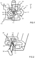
- Fig. 1 shows a sectional view through an assembled extrusion profile 100 according to an embodiment.
- the extrusion profile 100 is deformable and consists of a permanently elastic elastomer material.
- the extrusion profile 100 is connected to a mounting profile 102 of a door 104 of a vehicle.
- the mounting profile 102 can be referred to as a TFL profile.
- the vehicle is, for example, a rail vehicle and the door 104 is a sliding door of the rail vehicle.
- An arrow-shaped mounting area 106 of the extrusion profile 100 is snapped into a T-slot 108 of the mounting profile 102.
- the extrusion profile 100 can be referred to as a pinch protection profile 100 for a door gap 110 of the door 104.
- the vehicle has a detection device 112 or detection unit 112 for detecting jamming of an object in the door gap 110.
- the extrusion profile 100 for example, two switching elements 114 which are continuous in the extrusion direction and which are connected to the detection device 112 via interfaces for signal transmission.
- the switching elements 114 are spaced apart from one another by an intermediate space 116 or a gap 116 oriented transversely to a detection direction.
- the detection device 112 is designed to detect when the two switching elements 114 approach or touch each other.
- the detection device 112 can be designed to detect such an approach or contact, which can result from a deformation of the extrusion profile 100 during a pinching process, via a current measurement, capacitive or inductive measurement.
- the deformation acting on an outside of the extrusion profile 100 is transmitted to one of the switching elements 114 by a transmission device 118 of the extrusion profile 100.
- the transmission device 118 has a suitable mechanical structure, here, for example, two V-shaped ribs 120, which connect an arcuously projecting contact surface 122 of the extrusion profile 100 to the elastomer material in the region of the switching element 114.
- Profile 100 designed in such a way that the path or the deformation of the rubber on the contact surface 122 forming a front edge of the extrusion profile 100 is transmitted with a suitable transmission ratio, so that the sensitivity of the at least one switching element 114 can thus be set or controlled.
- the switching elements 114 have, for example, an electrically conductive material, so that an electrical contact is produced when the switching elements are touched.
- the detection device 112 registers a resulting current flow and can provide a pinching signal, for example to stop the door 104 from being driven.
- the switching elements 114 are strips made of metal, in particular stainless steel.
- the tapes 114 are extruded with the elastomeric material. When extruding, the elastomer material bonds firmly to the metal.
- the switching elements 114 can be damaged only with difficulty by the bands 114 made of metal. This protects the anti-trap profile 100 against vandalism, for example.
- FIG. 1 shows Fig. 1 using the example of a cross section of an extrusion profile 100 with integrated detection in the form of integrated pinch protection or integrated pinch detection in entry systems.
- the switching elements 114 such as an electrical switch or optical fiber, are already integrated directly into the profile 100 or coextruded.
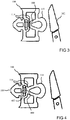
- Fig. 2 shows a spatial representation of an extrusion profile 100 according to an embodiment.
- the extrusion profile 100 essentially corresponds to the extrusion profile in FIG Fig. 1 ,
- a cut surface of the extrusion profile 100 is shown transversely to a main direction of extent of the extrusion profile 100.
- the extrusion profile 100 has been cut to length from an endless strand at the cut surface.
- Switching elements 114 have been severed.
- the cut surface of the elastomer material is thus also a cut surface of the switching elements 114.
- the switching elements 114 are electrically conductive here.
- a terminating resistor 200 is shown here, which electrically connects the switching elements 114 to one another.
- a defined quiescent current can flow through the switching elements 114 via the terminating resistor 200. If no quiescent current flows, the circuit is interrupted, which indicates a defect, such as a line break or damage to at least one of the switching elements. In this way, a line break in the integrated electrical safety edge 114 can be detected using the closed-circuit principle.
- the terminating resistor 200 which is of a suitable size, is attached.
- an end cap 202 that is shaped to close the gap 116 between the switching elements 114 at the interface.
- the end cap 202 has two chamfered pins which are inserted into cylindrical channels formed on both sides of the intermediate space 116 in the extrusion profile 100.
- the end cap 202 can also be glued or welded to the elastomer material.
- the resulting continuous material is cut to the desired length as required and the electrical or optical connections are made.
- the terminating resistor 200 is attached for function monitoring.
- the extrusion profile 100 also referred to as a system
- the end cap 202 also referred to as a plug
- the encapsulation takes place in that the end cap 202 is glued in or molded on.
- the switching elements 114 in the form of electrically conductive strips consist of electrically conductive materials.
- the switching elements 114 can be made of metal, with stainless steel being advantageous in terms of long-term durability.
- the switching elements 114 be made of an elastomer. The elastomer can be extruded in combination with metal wires.
- a switching element 114 in the form of an optical waveguide and additionally or alternatively a switching element 114 in the form of a reflector 114, a switching strip or a band switch can also be extruded.
- the switching elements 114 are optical switching elements 114.
- One of the switching elements 114 has a light guide and the other switching element 114 has a reflector.
- the light guide is extruded with the elastomer material.
- the reflector is evaporated after extrusion.
- a metal strip or the like or as follows based on Fig. 4 described a sufficiently thick metallic wire can be extruded with elastomer strips. With elastomer strips, the protection can be as in Fig. 3 can be increased by an additional deposit. Likewise, the detection unit 114 as in FIG Fig. 5 be moved into the door leaf profile.
- Fig. 3 shows a sectional view through an extrusion profile 100 with a cut protection device 300 according to an embodiment.
- the extrusion profile 100 essentially corresponds to the extrusion profiles in FIGS Figures 1 and 2 .
- an additional metallic or similar insert as cut protection device 300 is integrated into the elastomer material between the transmission device 118 and the area of the switching elements 114.
- the cut protection device 300 has been extruded in the form of a metal strip with the elastomer material to form the endless extrusion profile 100.
- the extrusion profile 100 shown here has increased protection against vandalism.
- the switching elements 114 embodied here as switching strips are protected by the cut protection device 300 when a knife 302 detects the Finger protection rubber of the extrusion profile 100 cuts through.
- the function of the pinch detection is also given in the event of profound damage to the extrusion profile 100.
- Fig. 4 shows a sectional view through a reinforced extrusion profile 100 according to an embodiment.
- the extrusion profile 100 essentially corresponds to the extrusion profiles in FIGS Figures 1 and 2 .
- the switching elements 114 are extruded from electrically conductive elastomer material.
- reinforcing, electrically conductive metal wires 400, 402 are integrated in the switching elements 114 here.
- the metal wires 400, 402 have different thicknesses.
- the metal wire 400 which is arranged in the switching element 114 facing the transmission device 118, is thicker than the metal wire 402, which faces the fastening area 106.
- Fig. 5 shows a sectional view through an extrusion profile 100 with protected switching elements 114 according to an embodiment.
- An outer contour of the extrusion profile 100 essentially corresponds to that in FIGS Figures 1 to 4 shown extrusion profiles.
- the switching elements 114 are arranged here in the interior of the fastening area 106 and thus in a safe area.
- the fastening area 106 is as in FIG Fig. 1 shown, arranged in a T-slot and thus enclosed on three sides by metal.
- the mounting profile is cut-resistant.
- the extrusion profile 100 shown here is therefore very well protected against vandalism or cuts.
- the fastening area 106 is an extension of the extrusion profile 100 which protrudes from a side of the extrusion profile 100 which is opposite the contact surface 122.
- the fastening area 106 has two mutually opposite latching hooks which enable the extrusion profile 100 to be clamped in the mounting profile.
- Fig. 6 shows a flow chart of a method for producing an extrusion profile according to an embodiment.
- the process can create an extrusion profile as described in the Figures 1 to 5 is shown to be produced.
- the method includes a step 600 of extruding and a step 602 of Integrate on.
- step 600 of extrusion an elastomeric material is extruded through a die of an extruder to the extrusion profile.
- step 602 of the integration at least one switching element is integrated into the extrusion profile.
- the switching element is embedded in the elastomer material during extrusion 600.
- the switching element emerges as an endless material or roll material with the elastomer material from the nozzle of the extruder.
- an electrical conductor or a reflector can also be applied in a further manufacturing process step.
- the conductor or reflector can be vapor-deposited, for example.
- the extruded continuous material is cut in a step 604 of cutting to length after step 600 of extrusion and step 602 of integrating into pieces of a desired length.
- the elastomer material and the at least one switching element are cut through at a cut surface by a cutting device.
- Fig. 7 shows a schematic representation of a vehicle 700, here for example a rail vehicle, according to an embodiment.
- vehicle 700 has a door 104, the door leaf 704 of which is provided along one edge with a pinch protection in the form of a door rubber, which is designed as an extrusion profile 100, as described with reference to the previous figures.
- Fig. 8 shows a sectional view through an extrusion profile 100 with a switching element 114 designed as a plunger anchor according to an exemplary embodiment.
- An outer contour of the extrusion profile 100 essentially corresponds to that in FIGS Figures 1 to 5 shown extrusion profiles.
- an electrical coil 800 is integrated in the elastomer material in the fastening area 106.
- the plunger anchor 114 is extruded as a strip with the elastomer material.
- the plunger anchor 114 is coupled to the transmission device 118 and is oriented essentially in a direction of movement expected when the extrusion profile 100 is compressed.
- the plunger anchor 114 projects into a cavity of the Extrusion profile 100 into it.
- the plunger 114 is movable in the direction of movement within the cavity.
- the coil 800 is composed of two co-extruded partial windings.
- the partial windings are arranged on both sides of the plunger armature 114 and cut to length with the elastomer material and the plunger armature 114.
- the partial windings have been electrically connected to one another at the cut surfaces in order to form the coil 800.
- a coil plane of the coil 800 is oriented transversely or perpendicular to the direction of movement of the plunger armature 114.
- the coil 800 is not arranged in the extrusion profile 100, but in the mounting profile of the door. An electrical connection of the extrusion profile 100 to the detection device can thereby be dispensed with.
- FIG. 8 shows Fig. 8 an extrusion profile 100 for inductive detection.
- the metal strip 114 which is also extruded with the extrusion profile 100 designed here as a finger protection profile, plunges into the coil 800.
- the resulting change in the magnetic field is evaluated with a suitable device, whereby a pinching can be detected.
- the coil 800 can also be attached after the extruded profile 100 has been cut off. It is not necessary to wind the spool 800 on the finger protection profile 100, but can also be attached to the door leaf profile.
- Fig. 9 shows a sectional view through an extrusion profile 100 with obliquely arranged switching elements 114 according to an embodiment.
- the extrusion profile 100 essentially corresponds to that in FIG Fig. 1 shown extrusion profile.
- the two switching elements 114 are in one here Angle to the expected direction of movement of the transfer device 118 when the extrusion profile 100 is compressed.
- the arrangement of the switching element 114 is arbitrary.
- Fig. 10 shows a sectional view through an extrusion profile 100 with a light guide 114 as a switching element according to an embodiment.
- the light guide 114 is extruded with the elastomer material.
- the light guide 114 is arranged in the gap 116 and connected to both sides of the gap 116.
- a light source not shown here, is arranged at a first end of the light guide 114.
- a light sensor (not shown here) is arranged at a second end of the light guide 114 opposite the first end.
- the light source and the light sensor are arranged at the same end of the light guide 114.
- a reflector is arranged at the second end.
- the light source is designed to couple light into the light guide 114.
- the light is totally reflected at an interface of the light guide 114 and directed to the light sensor.
- the light sensor maps an incoming light intensity in an electrical signal for the detection device. If the extrusion profile 100 is deformed, the light guide 114 is also deformed. Due to the deformation, the light is less reflected at the interface. The light intensity arriving at the light sensor is reduced. The change in light intensity is reflected in the signal.
- Fig. 11 shows a sectional view through an extrusion profile 100 with different switching elements 114 according to an embodiment.
- An outer contour of the extrusion profile 100 essentially corresponds to one of the extrusion profiles shown in the previous figures.
- the extrusion profile 100 has switching elements 114 with different sensor principles.
- switching elements 114 with different sensor principles.
- This combination of two different sensor principles is chosen only as an example.
- switching elements 114 can also be used other sensor principles or switching elements 114 with the same sensor principle can be combined in an extrusion profile 100.
Landscapes
- Engineering & Computer Science (AREA)
- Mechanical Engineering (AREA)
- Push-Button Switches (AREA)
- Power-Operated Mechanisms For Wings (AREA)
Description
- Die Erfindung geht aus von einer Vorrichtung und einem Verfahren nach Gattung der unabhängigen Ansprüche 1 und 11.
- An einem Türspalt eines Fahrzeugs kann eine Klemmschutzeinrichtung angeordnet sein, um beispielsweise beim Einklemmen von Fingern in dem Türspalt Verletzungen zu vermeiden.
- Die
DE 10 2012 101543 A1 offenbart ein Herstellungsverfahren einer Fremdkörper-Erfassungsvorrichtung. Dabei wird ein elastischer Isolator gebildet, der einen Befestigungsabschnitt und einen inneren peripheren Abschnitt aufweist, auf dem eine Mehrzahl von Elektroden auf eine solche Art und Weise angeordnet sind, dass jede der Elektroden von den anderen entfernt liegt. DieEP 1 447512 A2 offenbart eine Sicherheitseinrichtung für Türen, wobei die Sicherheitseinrichtung einen Profilkörper aus elastomerem Material mit zumindest zwei entlang des Profilkörpers verlaufenden Hohlräumen aufweist, wobei in den Hohlräumen Schaltelemente vorgesehen sind. DieDE 197 20 713 C1 offenbart ein Dichtungsprofil zur Abdichtung einer kraftbetätigten Schließeinrichtung. DieWO 00/57013 A1 - Vor diesem Hintergrund werden mit dem hier vorgestellten Ansatz ein alternatives Extrusionsprofil aus einem Elastomermaterial und ein Verfahren zum Herstellen eines Extrusionsprofils mit verbessertem Vandalismusschutz sowie eine Tür für ein Fahrzeug mit einem erfindungsgemäßen Extrusionsprofil vorgestellt.
- Ein Einklemmen im Türspalt kann durch eine Erkennungseinrichtung erkannt werden, die in einer Klemmschutzeinrichtung integriert ist. Zumindest Teile der Erkennungseinrichtung können unmittelbar in einen Türgummi der Klemmschutzeinrichtung integriert sein. Dadurch können der Türgummi und die integrierten Teile zusammen auf Länge geschnitten werden.
- Dadurch ergibt sich eine integrale Bauweise, die eine Reduktion von Bauteilen ermöglicht, da mehrere Funktionen, wie der Einklemmschutz, die Einklemmerkennung und der "Einklemmschmerz" in einem Bauteil verschmolzen sind. Es ergibt sich ein einfaches Funktionsprinzip durch ein abgekapseltes wartungsfreies System, das unempfindlich gegen äußere Einflüsse ist. Eine Auswertung mit bestehenden Türsteuerungen ist möglich. Ein Funktionsausfall kann detektiert werden und in bestimmten Ausführungsvarianten ergibt sich eine erhöhte Vandalismus-Sicherheit.
- Es wird ein Extrusionsprofil für eine Tür für ein Fahrzeug vorgestellt, wobei das Extrusionsprofil aus einem Elastomermaterial mit zumindest einem durchgehenden Schaltelement für eine Detektionseinrichtung zum Detektieren einer Kompression des Extrusionsprofils und einer durchgehenden Schnittschutzeinrichtung gefertigt ist, wobei das Schaltelement und die Schnittschutzeinrichtung in das Extrusionsprofil integriert ist und mit dem Extrusionsprofil ablängbar ist, wobei die Schnittschutzeinrichtung ein parallel zu dem zumindest einen Schaltelement ausgerichtetes, in das Elastomermaterial eingebettetes Schnittschutzelement aufweist, und wobei das Schnittschutzelement in Bezug auf eine angenommene Schnittrichtung vor dem Schaltelement angeordnet ist, um das Schaltelement zu schützen.
- Unter einem Fahrzeug kann beispielsweise ein Fahrzeug zur Personenbeförderung verstanden werden. Dabei kann es sich um ein Schienenfahrzeug oder ein Straßenfahrzeug handeln. Zudem kann das Extrusionsprofil auch bei anderen Anwendungsgebieten eingesetzt werden, bei denen das Erkennen eines Einklemmens oder einer Verformung, beispielsweise bei einem Schließvorgang, von Interesse ist. Unter einem Extrusionsprofil kann ein theoretisch mit unendlicher Länge herstellbarer Strang mit gleichbleibender Querschnittsfläche verstanden werden. Ein Elastomermaterial kann elastische Materialeigenschaften aufweisen. Beispielsweise kann das Elastomermaterial Gummi oder ein geeigneter Kunststoff sein. Ein Schaltelement kann dazu ausgebildet sein, unter Verwendung eines Gegenstücks, welches auch ein gleichartiges Schaltelement sein kann, eine Kompression des Extrusionsprofils in einem Signal abzubilden. Das Schaltelement kann ebenso wie das Extrusionsprofil theoretisch endlos ausgeführt werden. Eine Detektionseinrichtung kann elektrische Komponenten zum Betreiben des Schaltelements aufweisen. Eine Schnittschutzeinrichtung kann als Vandalismusschutzeinrichtung bezeichnet werden. Die Schutzeinrichtung ist benachbart zu dem zumindest einen Schaltelement angeordnet. Die Schnittschutzeinrichtung ist mit dem Extrusionsprofil ablängbar. Die Schnittschutzeinrichtung kann unempfindlich gegen Schnitte ausgeformt sein. Durch die Schnittschutzeinrichtung weist das Extrusionsprofil eine erhöhte Vandalismussicherheit auf.
- Das Schaltelement kann ein in einer Haupterstreckungsrichtung des Extrusionsprofils ausgerichtetes optisches Reflektorelement sein. Ein Reflektorelement kann ein reflektierender schlauchförmiger Hohlraum sein. Eine Oberfläche des Hohlraums kann glatt und/oder spiegelnd sein. Dadurch kann das Reflektorelement auch auf gebogene Profile angewendet werden. Ein Reflektor kann beispielsweise durch Extrusion über eine Eigenschaft des Materials selbst hergestellt werden. Ebenso kann der Reflektor nachträglich aufgedampft werden. Das Reflektorelement kann mit einem Sender und einen Empfänger gekoppelt werden. Durch eine Kompression des Reflektorelements, die durch eine Kompression des Extrusionsprofils hervorgerufen werden kann, wird eine Dämpfung des Reflektorelements beziehungsweise ein Verlust einer durch das Reflektorelement geleiteten Strahlung erhöht und am Empfänger kann eine entsprechende Veränderung detektiert und ausgewertet werden.
- Das Schaltelement kann ein in der Haupterstreckungsrichtung ausgerichteter Lichtleiter sein. Ein Lichtleiter, auch Lichtwellenleiter genannt, reflektiert Licht über eine Totalreflexion an einer Grenzfläche des Lichtwellenleiters. Der Lichtleiter kann entsprechend zu dem Reflektorelement mit einem Sender und einem Empfänger ergänzt werden. Durch eine Biegung oder Kompression des Lichtleiters, welche durch Kompression des Extrusionsprofils hervorgerufen werden kann, wird die Dämpfung beziehungsweise der Verlust einer durch das Reflektorelement geleiteten Strahlung erhöht und am Empfänger kann eine entsprechende Veränderung detektiert und ausgewertet werden.
- Das Schaltelement kann anschließend an das Extrudieren in das Extrusionsprofil eingebracht sein. Beispielsweise kann das Schaltelement aufgedampft werden. Durch das nachträgliche Integrieren des Schaltelements können Materialien verwendet werden, die nicht extrudierbar sind. Ebenso kann ein erstes Schaltelement extrudiert werden und ein zweites Schaltelement anschließend eingebracht werden.
- Das Schaltelement kann in das Elastomermaterial eingebettet sein. Das Schaltelement kann extrudiert sein. Das zumindest eine Schaltelement kann zusammen mit dem Elastomermaterial aus einer konturierten Düse extrudiert werden. Dadurch kann eine sichere Verbindung zwischen dem Schaltelement und dem Elastomermaterial erreicht werden und es ist kein separater Herstellungsschritt zum Kombinieren des zumindest einen Schaltelements und des Extrusionsprofils erforderlich.
- Das Schaltelement kann ein Tauchanker zum Eintauchen in eine Spuleneinrichtung sein. Der Tauchanker kann dazu ausgeformt sein, beim Eintauchen in die Spuleneinrichtung ein Magnetfeld der Spuleneinrichtung zu beeinflussen. Eine entsprechende Eintauchbewegung kann durch eine Kompression des Extrusionsprofils hervorgerufen werden. Der Tauchanker kann aus einem weichmagnetischen Werkstoff gefertigt sein. Beispielsweise kann der Tauchanker elektrisch leitend sein. Das Schaltelement ändert den magnetischen Widerstand des Magnetkreises. Das Schaltelement kann quer zu einer Spulenebenen der Spuleneinrichtung beweglich gelagert sein. Die Spuleneinrichtung kann gemäß einer Ausführungsform in das Extrusionsprofil integriert sein. Beispielsweise können Teilwicklungen der Spuleneinrichtung in das Elastomermaterial integriert sein und mit dem Extrusionsprofil abgelängt werden. Anschließend können die Teilwicklungen an den Schnittkanten des Extrusionsprofils elektrisch leitend miteinander verbunden werden, um eine elektrische Spule auszubilden. Die Spule kann auch nach dem Extrusionsprozess angebracht werden.
- Die Detektionseinrichtung kann zwei Schaltelemente in Form von zwei in einer Haupterstreckungsrichtung des Extrusionsprofils ausgerichteten elektrischen Leitern aufweisen. Die Leiter können durch einen komprimierbaren Zwischenraum voneinander beabstandet sein. Ein Zwischenraum kann als Spalt bezeichnet werden. Die Leiter können Kontaktflächen aufweisen, über die bei einer Kompression des Zwischenraums ein Stromfluss zwischen den Leitern erfolgen kann. Durch den elektrischen Kontakt zwischen zwei Leitern kann die Kompression einfach erfasst werden. Gemäß unterschiedlichen Ausführungsbeispielen kann ein entsprechender elektrischer Leiter beispielsweise aus Metall und/oder aus einem elektrisch leitfähigen Elastomermaterial ausgeformt sein. Ein elektrisch leitfähiges Elastomermaterial kann beispielsweise ein mit elektrisch leitfähigen Partikeln durchsetztes Elastomermaterial sein. Es kann auch ein metallischer Leiter in einem elektrisch leitenden Elastomer eingebettet sein.
- Die Schnittschutzeinrichtung weist ein parallel zu dem Schaltelement ausgerichtetes, in das Elastomermaterial eingebettetes Schnittschutzelement auf. Das Schnittschutzelement kann metallisch, beispielsweise ein Metallband oder ein Metallnetz sein. Ebenso kann das Schnittschutzelement aus einem faserverstärkten Kunststoffmaterial, wie beispielsweise GFK oder CFK sein. Das Schnittschutzelement kann auch ein textiles Schnittschutzmaterial sein. Das Schnittschutzelement kann so ausgerichtet sein, dass die Grundfunktion des Einklemmschutzes beziehungsweise der Einklemmerkennung des Schaltelements weiterhin gegeben ist. Das Schnittschutzelement kann extrudiert sein. Das Schnittschutzelement ist in Bezug auf eine angenommene Schnittrichtung vor dem Schaltelement angeordnet, um das Schaltelement zu schützen.
- Das Schaltelement kann in einem Befestigungsbereich des Extrusionsprofils angeordnet sein. Der Befestigungsbereich kann vorgesehen sein, um das Extrusionsprofil beispielsweise an einem Türblatt zu befestigen. Dazu kann der Befestigungsbereich in eine Aufnahmeeinrichtung, beispielsweise eine Aufnahmekontur des Türblatts, eingefügt werden. Bei einer geeigneten Ausformung der Aufnahmeeinrichtung kann der Befestigungsbereich im montierten Zustand schnittgeschützt angeordnet sein. Durch die Position des zumindest einen Schaltelements im Befestigungsbereich ist das Schaltelement sehr gut vor Vandalismus geschützt.
- Das Extrusionsprofil kann eine Übertragungseinrichtung aufweisen. Die Übertragungseinrichtung kann zwischen einer Berührfläche des Extrusionsprofils und dem Schaltelement angeordnet sein. Die Übertragungseinrichtung kann dazu ausgebildet sein, eine Verformung der Berührfläche auf das Schaltelement zu übertragen. Unter der Berührfläche kann eine Außenfläche des Extrusionsprofils verstanden werden, die im Falle eines Einklemmvorgangs verformt wird. Die Übertragungseinrichtung ermöglicht eine genaue Erfassung der Verformung, auch wenn das zumindest eine Schaltelement auf einer von der Berührfläche entfernten Seite des Extrusionsprofils angeordnet ist.
- Eine solche Übertragungseinrichtung kann eine mechanische Struktur aufweisen, die in einer Übertragungsrichtung von der Berührungsfläche zu dem zumindest einen Schaltelement eine vorbestimmte Steifigkeit aufweist. Die Steifigkeit charakterisiert dabei, wie weit das Schaltelement bei einem Druck auf die Berührfläche verformt wird. Beispielsweise kann durch die Übertragungseinrichtung ein Übersetzungsverhältnis zwischen einer durch eine Deformation hervorgerufenen Auslenkung eines Abschnitts der Berührfläche und einer Auslenkung eines auf Höhe des Abschnitts der Berührfläche liegenden Abschnitts eines Schaltelements definiert werden. Auch kann die mechanische Struktur beispielsweise so ausgeformt sein, dass eine Beschädigung des Schaltelements bei einer starken Deformation des Extrusionsprofils verhindert wird.
- Eine Tür für ein Fahrzeug umfasst ein Türblatt und ein an einer Kante des Türblatts angeordnetes erfindungsgemäßes Extrusionsprofil. Auf diese Weise kann das Extrusionsprofil vorteilhaft im Zusammenhang mit einer Tür eingesetzt werden. Alternativ oder zusätzlich zu einer Anordnung des Extrusionsprofils kann das Extrusionsprofil beispielsweise auch an einem Türrahmen angeordnet sein. Das Extrusionsprofil kann als Bestandteil der Tür aufgefasst werden.
- Weiterhin wird ein Verfahren zum Herstellen eines erfindungsgemäßen Extrusionsprofils vorgestellt, wobei das Verfahren die folgenden Schritte aufweist:
- Extrudieren des Elastomermaterials zu dem Extrusionsprofil; und Integrieren des Schaltelements und der Schnittschutzeinrichtung in das Extrusionsprofil, wobei die Schnittschutzeinrichtung ein parallel zu dem zumindest einen Schaltelement ausgerichtetes Schnittschutzelement aufweist, das in das Elastomermaterial eingebettet wird, und wobei das Schnittschutzelement in Bezug auf eine angenommene Schnittrichtung vor dem Schaltelement angeordnet wird, um das Schaltelement zu schützen.
- Die Schritte des Extrudierens und des Integrierens können zeitgleich ausgeführt werden. Zumindest ein Schaltelement und/oder die Schnittschutzeinrichtung kann zeitgleich mit dem Elastomermaterial extrudiert werden. Durch ein zeitgleiches Extrudieren und Integrieren kann das Extrusionsprofil einfach und schnell hergestellt werden. Es kann auch beides integriert sein.
- Das Schaltelement und/oder ein weiteres Schaltelement kann auf das Elastomermaterial aufgedampft werden. Durch ein Aufdampfen kann eine geringe Schichtdicke erreicht werden.
- Das Verfahren kann einen Schritt des Ablängens des Extrusionsprofils auf eine gewünschte Länge aufweisen. Dabei kann das zumindest eine Schaltelement und/oder die Schnittschutzeinrichtung zeitgleich und in einem Arbeitsschritt mit dem Extrusionsprofil auf die Länge abgelängt werden. Das Ablängen kann beispielsweise kurz nach einer Extrudierdüse erfolgen.
- Ausführungsbeispiele des hier vorgestellten Ansatzes sind in den Zeichnungen dargestellt und in der nachfolgenden Beschreibung näher erläutert. Es zeigt:
- Fig. 1
- eine Schnittdarstellung durch ein montiertes Extrusionsprofil gemäß einem Ausführungsbeispiel;
- Fig. 2
- eine räumliche Darstellung eines Extrusionsprofils gemäß einem Ausführungsbeispiel;
- Fig. 3
- eine Schnittdarstellung durch ein Extrusionsprofil mit einer Schnittschutzeinrichtung gemäß einem Ausführungsbeispiel;
- Fig. 4
- eine Schnittdarstellung durch ein verstärktes Extrusionsprofil gemäß einem Ausführungsbeispiel;
- Fig. 5
- eine Schnittdarstellung durch ein Extrusionsprofil mit geschützten Schaltelementen gemäß einem Ausführungsbeispiel;
- Fig. 6
- ein Ablaufdiagramm eines Verfahrens zum Herstellen eines Extrusionsprofils gemäß einem Ausführungsbeispiel;
- Fig. 7
- eine schematische Darstellung eines Fahrzeugs mit einem Extrusionsprofil gemäß einem Ausführungsbeispiel;
- Fig. 8
- eine Schnittdarstellung durch ein Extrusionsprofil mit einem als Tauchanker ausgebildeten Schaltelement gemäß einem Ausführungsbeispiel;
- Fig. 9
- eine Schnittdarstellung durch ein Extrusionsprofil mit schräg angeordneten Schaltelementen gemäß einem Ausführungsbeispiel;
- Fig. 10
- eine Schnittdarstellung durch ein Extrusionsprofil mit einem Lichtleiter als Schaltelement gemäß einem Ausführungsbeispiel; und
- Fig. 11
- eine Schnittdarstellung durch ein Extrusionsprofil mit unterschiedlichen Schaltelementen gemäß einem Ausführungsbeispiel.
- In der nachfolgenden Beschreibung günstiger Ausführungsbeispiele der vorliegenden Erfindung werden für die in den verschiedenen Figuren dargestellten und ähnlich wirkenden Elemente gleiche oder ähnliche Bezugszeichen verwendet, wobei auf eine wiederholte Beschreibung dieser Elemente verzichtet wird.
-
Fig. 1 zeigt eine Schnittdarstellung durch ein montiertes Extrusionsprofil 100 gemäß einem Ausführungsbeispiel. Das Extrusionsprofil 100 ist verformbar und besteht aus einem dauerelastischen Elastomermaterial. Das Extrusionsprofil 100 ist mit einem Montageprofil 102 einer Türe 104 eines Fahrzeugs verbunden. Das Montageprofil 102 kann als TFL-Profil bezeichnet werden. Das Fahrzeug ist beispielsweise ein Schienenfahrzeug und die Türe 104 eine Schiebetüre des Schienenfahrzeugs. Ein pfeilförmiger Montagebereich 106 des Extrusionsprofils 100 ist in einer T-Nut 108 des Montageprofils 102 eingerastet. - Das Extrusionsprofil 100 kann als Klemmschutzprofil 100 für einen Türspalt 110 der Türe 104 bezeichnet werden. Das Fahrzeug weist gemäß einem Ausführungsbeispiel eine Detektionseinrichtung 112 beziehungsweise Detektionseinheit 112 zum Detektieren eines Einklemmens eines Gegenstands in dem Türspalt 110 auf. Dazu sind in das Extrusionsprofil 100 gemäß diesem Ausführungsbeispiel beispielhaft zwei in Extrusionsrichtung durchgehende Schaltelemente 114 eingebettet, die über Schnittstellen signalübertragungsfähig mit der Detektionseinrichtung 112 verbunden sind. Die Schaltelemente 114 sind durch einen quer zu einer Detektionsrichtung ausgerichteten Zwischenraum 116 beziehungsweise einen Spalt 116 voneinander beabstandet. Die Detektionseinrichtung 112 ist gemäß einem Ausführungsbeispiel ausgebildet, um zu detektieren, wenn sich die beiden Schaltelemente 114 einander annähern oder berühren. Beispielsweise kann die Detektionseinrichtung 112 ausgebildet sein, um eine solche Annäherung oder Berührung, die aus einer Verformung des Extrusionsprofils 100 bei einem Einklemmvorgang resultieren kann, über eine Strommessung, kapazitive oder induktive Messung zu detektieren.
- Gemäß einem Ausführungsbeispiel wird bei einem Einklemmvorgang die auf eine Außenseite des Extrusionsprofils 100 wirkende Verformung durch eine Übertragungseinrichtung 118 des Extrusionsprofils 100 auf eines der Schaltelemente 114 übertragen. Die Übertragungseinrichtung 118 weist dazu eine geeignete mechanische Struktur, hier beispielsweise zwei V-förmig angeordnete Rippen 120 auf, die eine bogenförmig hervorstehende Berührfläche 122 des Extrusionsprofils 100 mit dem Elastomermaterial im Bereich des Schaltelements 114 verbinden. Hier ist das Profil 100 derart gestaltet, dass der Weg beziehungsweise die Verformung des Gummis an der eine Vorderkante des Extrusionsprofils 100 ausformenden Berührfläche 122 mit einem geeigneten Übersetzungsverhältnis übertragen wird, sodass damit die Empfindlichkeit des zumindest einen Schaltelements 114 eingestellt beziehungsweise gesteuert werden kann.
- Die Schaltelemente 114 weisen beispielsweise ein elektrisch leitendes Material auf, sodass bei einer Berührung der Schaltelemente ein elektrischer Kontakt hergestellt wird. Die Detektionseinrichtung 112 registriert einen resultierenden Stromfluss und kann ein Einklemmsignal bereitstellen, beispielsweise um einen Antrieb der Türe 104 anzuhalten.
- In einem Ausführungsbeispiel sind die Schaltelemente 114 Bänder aus Metall, insbesondere aus Edelstahl. Die Bänder 114 sind mit dem Elastomermaterial extrudiert. Beim Extrudieren verbindet sich das Elastomermaterial fest mit dem Metall. Durch die Bänder 114 aus Metall können die Schaltelemente 114 nur schwer beschädigt werden. Dadurch ist das Klemmschutzprofil 100 beispielsweise gegen Vandalismus geschützt.
- Mit anderen Worten zeigt
Fig. 1 am Beispiel eines Querschnitts eines Extrusionsprofils 100 mit integrierter Detektierung in Form eines integrierten Einklemmschutzes oder integrierter Einklemmerkennung bei Einstiegssystemen. Im Gegensatz zu bisherigen Detektionsmöglichkeiten für Einklemmschutz, bei dem die Sensorik, wie beispielsweise eine Schaltleiste, nach der Extrusion des Fingerschutzprofils eingebaut wird, sind bei dem hier vorgestellten Ansatz die Schaltelemente 114, wie ein elektrischer Schalter oder Lichtwellenleiter bereits direkt in das Profil 100 integriert beziehungsweise mitextrudiert. -
Fig. 2 zeigt eine räumliche Darstellung eines Extrusionsprofils 100 gemäß einem Ausführungsbeispiel. Das Extrusionsprofil 100 entspricht im Wesentlichen dem Extrusionsprofil inFig. 1 . Es ist eine Schnittfläche des Extrusionsprofils 100 quer zu einer Haupterstreckungsrichtung des Extrusionsprofils 100 dargestellt. An der Schnittfläche ist das Extrusionsprofil 100 von einem Endlosstrang abgelängt worden. Beim Ablängen sind auch die vor dem Ablängen in das Extrusionsprofil 100 integrierten Schaltelemente 114 durchtrennt worden. Damit ist die Schnittfläche des Elastomermaterials auch eine Schnittfläche der Schaltelemente 114. - Die Schaltelemente 114 sind hier elektrisch leitend. Zusätzlich ist hier ein Abschlusswiderstand 200 dargestellt, der die Schaltelemente 114 elektrisch miteinander verbindet. Über den Abschlusswiderstand 200 kann ein definierter Ruhestrom durch die Schaltelemente 114 fließen. Wenn kein Ruhestrom fließt, ist der Stromkreis unterbrochen, was auf einen Defekt, wie einen Leitungsbruch oder eine Beschädigung zumindest eines der Schaltelemente hindeutet. Auf diese Weise kann ein Leitungsbruch bei der integrierten elektrischen Schaltleiste 114 mithilfe des Ruhestromprinzips erkannt werden. Aus diesem Grund wird gemäß einem Ausführungsbeispiel der in einer geeigneten Größe ausgeführte Abschlusswiderstand 200 angebracht.
- Weiterhin ist eine Endkappe 202 dargestellt, die ausgeformt ist, um den Zwischenraum 116 zwischen den Schaltelementen 114 an der Schnittstelle zu verschließen. Die Endkappe 202 weist zwei angefaste Zapfen auf, die in beidseitig des Zwischenraums 116 in dem Extrusionsprofil 100 ausgebildete zylindrische Kanäle eingesteckt werden. Die Endkappe 202 kann auch mit dem Elastomermaterial verklebt oder verschweißt werden.
- Nach der Extrusion wird das entstehende Endlosmaterial je nach Bedarf in der gewünschten Länge abgeschnitten und die elektrischen beziehungsweise optischen Anschlüsse werden angebracht. Hier ist beispielsweise der Abschlusswiderstand 200 zur Funktionsüberwachung angebracht. In einem weiteren Schritt kann das auch als System bezeichnete Extrusionsprofil 100, um den Eintritt von Feuchtigkeit zu vermeiden, an einer oder beiden Enden durch die Endkappe 202, auch als Stopfen bezeichnet, abgekapselt werden. Die Abkapselung erfolgt gemäß einem Ausführungsbeispiel dadurch, dass die Endkappe 202 eingeklebt oder angespritzt wird.
- Die gemäß einem Ausführungsbeispiel mitextrudierten Schaltelemente 114 in Form von elektrisch leitenden Streifen bestehen aus elektrisch leitenden Materialien. Beispielsweise können die Schaltelemente 114 aus Metall sein, wobei Edelstahl bezüglich der Langzeitbeständigkeit von Vorteil ist. Ebenso können die Schaltelemente 114 aus einem Elastomer sein. Der Elastomer kann in Kombination mit Metalldrähten extrudiert werden.
- Anstelle der elektrisch leitenden Streifen kann auch ein Schaltelement 114 in Form eines Lichtwellenleiters und zusätzlich oder alternativ ein Schaltelement 114 in Form eines Reflektors 114, einer Schaltleiste oder eines Bandschalter mitextrudiert werden.
- In einem Ausführungsbeispiel sind die Schaltelemente 114 optische Schaltelemente 114. Dabei weist eines der Schaltelemente 114 einen Lichtleiter und das andere Schaltelement 114 einen Reflektor auf. Der Lichtleiter ist mit dem Elastomermaterial extrudiert. Der Reflektor ist nach dem Extrudieren aufgedampft.
- Um die Vandalismus-Sicherheit der auf dem zumindest einen Schaltelement 114 basierenden Sensorik zu erhöhen, stehen unterschiedliche Möglichkeiten zur Verfügung. Beispielsweise kann, wie nachfolgend anhand von
Fig. 3 beschrieben, ein Metallstreifen oder Ähnliches oder wie nachfolgend anhand vonFig. 4 beschrieben, ein ausreichend dicker metallischer Draht bei Elastomerstreifen mitextrudiert werden. Bei Elastomerstreifen kann der Schutz wie inFig. 3 durch eine zusätzliche Einlage erhöht werden. Ebenso kann die Detektionseinheit 114 wie inFig. 5 in das Türflügelprofil verschoben werden. -
Fig. 3 zeigt eine Schnittdarstellung durch ein Extrusionsprofil 100 mit einer Schnittschutzeinrichtung 300 gemäß einem Ausführungsbeispiel. Das Extrusionsprofil 100 entspricht im Wesentlichen den Extrusionsprofilen in denFiguren 1 und 2 . Zusätzlich ist hier zwischen der Übertragungseinrichtung 118 und dem Bereich der Schaltelemente 114 eine zusätzliche metallische oder ähnliche Einlage als Schnittschutzeinrichtung 300 in das Elastomermaterial integriert. Die Schnittschutzeinrichtung 300 ist in Form eines Metallbands mit dem Elastomermaterial zu dem endlosen Extrusionsprofil 100 extrudiert worden. - Das hier dargestellte Extrusionsprofil 100 weist einen erhöhten Vandalismus-Schutz auf. Beispielsweise sind die hier als Schaltleisten ausgeführten Schaltelemente 114 durch die Schnittschutzeinrichtung 300 geschützt, wenn ein Messer 302 den Fingerschutzgummi des Extrusionsprofils 100 durchschneidet. Dadurch ist die Funktion der Einklemmerkennung auch bei einer tief greifenden Beschädigung des Extrusionsprofils 100 weiter gegeben.
-
Fig. 4 zeigt eine Schnittdarstellung durch ein verstärktes Extrusionsprofil 100 gemäß einem Ausführungsbeispiel. Das Extrusionsprofil 100 entspricht im Wesentlichen den Extrusionsprofilen in denFiguren 1 und 2 . Die Schaltelemente 114 sind hier aus elektrisch leitendem Elastomermaterial extrudiert. Zusätzlich sind hier verstärkende, elektrisch leitende Metalldrähte 400, 402 in die Schaltelemente 114 integriert. Die Metalldrähte 400, 402 sind unterschiedlich dick. Der Metalldraht 400, der in dem der Übertragungseinrichtung 118 zugewandten Schaltelement 114 angeordnet ist, ist dicker, als der Metalldraht 402, der dem Befestigungsbereich 106 zugewandt ist. -
Fig. 5 zeigt eine Schnittdarstellung durch ein Extrusionsprofil 100 mit geschützten Schaltelementen 114 gemäß einem Ausführungsbeispiel. Eine Außenkontur des Extrusionsprofils 100 entspricht im Wesentlichen einem der in denFiguren 1 bis 4 dargestellten Extrusionsprofilen. Im Gegensatz dazu sind die Schaltelemente 114 hier im Inneren des Befestigungsbereichs 106 und damit in einem sicheren Bereich angeordnet. Im verbauten Zustand ist der Befestigungsbereich 106 wie inFig. 1 gezeigt, in einer T-Nut angeordnet und damit an drei Seiten von Metall umschlossen. Das Montageprofil ist schnittresistent. Daher ist das hier dargestellte Extrusionsprofil 100 sehr gut gegen Vandalismus beziehungsweise Schnitte geschützt. - Der Befestigungsbereich 106 ist gemäß diesem Ausführungsbeispiel ein sich aus einer der Berührungsfläche 122 gegenüberliegenden Seite des Extrusionsprofils 100 hervorstehender Fortsatz des Extrusionsprofils 100. Der Befestigungsbereich 106 weist zwei einander gegenüberliegende Rasthaken auf, die ein Festklemmen des Extrusionsprofils 100 in dem Montageprofil ermöglichen.
-
Fig. 6 zeigt ein Ablaufdiagramm eines Verfahrens zum Herstellen eines Extrusionsprofils gemäß einem Ausführungsbeispiel. Durch das Verfahren kann ein Extrusionsprofil, wie es in denFiguren 1 bis 5 dargestellt ist, hergestellt werden. Das Verfahren weist einen Schritt 600 des Extrudierens und einen Schritt 602 des Integrierens auf. Im Schritt 600 des Extrudierens wird ein Elastomermaterial durch eine Düse eines Extruders zu dem Extrusionsprofil extrudiert. Im Schritt 602 des Integrierens wird zumindest ein Schaltelement in das Extrusionsprofil integriert. - In einem Ausführungsbeispiel wird das Schaltelement während des Extrudierens 600 in das Elastomermaterial eingebettet. Dazu tritt das Schaltelement als Endlosmaterial oder Rollenmaterial mit dem Elastomermaterial aus der Düse des Extruders aus.
- Alternativ kann auch ein elektrischer Leiter oder ein Reflektor in einem weiteren Herstell-Prozessschritt aufgetragen werden. Der Leiter oder Reflektor kann beispielsweise aufgedampft werden.
- In einem Ausführungsbeispiel wird das extrudierte Endlosmaterial in einem Schritt 604 des Ablängens nach dem Schritt 600 des Extrudierens und dem Schritt 602 des Integrierens auf Stücke mit einer gewünschten Länge abgelängt. Dabei werden das Elastomermaterial und das zumindest eine Schaltelement an einer Schnittfläche durch eine Ablängeinrichtung durchtrennt.
-
Fig. 7 zeigt eine schematische Darstellung eines Fahrzeugs 700, hier beispielsweise eines Schienenfahrzeugs, gemäß einem Ausführungsbeispiel. Das Fahrzeug 700 weist eine Tür 104 auf, deren Türblatt 704 entlang einer Kante mit einem Einklemmschutz in Form eines Türgummis versehen ist, der als ein Extrusionsprofil 100 ausgeführt ist, wie es anhand der vorangegangenen Figuren beschriebenen ist. -
Fig. 8 zeigt eine Schnittdarstellung durch ein Extrusionsprofil 100 mit einem als Tauchanker ausgebildeten Schaltelement 114 gemäß einem Ausführungsbeispiel. Eine Außenkontur des Extrusionsprofils 100 entspricht im Wesentlichen einem der in denFiguren 1 bis 5 dargestellten Extrusionsprofilen. Im Gegensatz dazu ist in dem Befestigungsbereich 106 eine elektrische Spule 800 in das Elastomermaterial integriert. Der Tauchanker 114 ist als Streifen mit dem Elastomermaterial extrudiert. Der Tauchanker 114 ist mit der Übertragungseinrichtung 118 gekoppelt und im Wesentlichen in einer bei einer Kompression des Extrusionsprofils 100 erwarteten Bewegungsrichtung ausgerichtet. Der Tauchanker 114 ragt in einen Hohlraum des Extrusionsprofils 100 hinein. Innerhalb des Hohlraums ist der Tauchanker 114 in der Bewegungsrichtung beweglich. - Die Spule 800 ist aus zwei mitextrudierten Teilwicklungen zusammengesetzt. Die Teilwicklungen sind beidseitig des Tauchankers 114 angeordnet und mit dem Elastomermaterial und dem Tauchanker 114 abgelängt worden. An den Schnittflächen sind die Teilwicklungen elektrisch miteinander verbunden worden, um die Spule 800 auszubilden. Eine Spulenebene der Spule 800 ist quer beziehungsweise senkrecht zu der Bewegungsrichtung des Tauchankers 114 ausgerichtet.
- Wenn der Tauchanker 114 relativ zu der Spule 800 bewegt wird beziehungsweise in sie eintaucht, ändert sich eine Induktivität der Spule 800. Die Induktivität wird erfasst. Die Änderung der Induktivität signalisiert eine Verformung des Extrusionsprofils 100.
- In einem nicht dargestellten Ausführungsbeispiel ist die Spule 800 nicht in dem in dem Extrusionsprofil 100, sondern in dem Montageprofil der Türe angeordnet. Dadurch kann auf eine elektrische Verbindung des Extrusionsprofils 100 zu der Detektionseinrichtung verzichtet werden.
- Mit anderen Worten zeigt
Fig. 8 ein Extrusionsprofil 100 zur induktiven Detektierung. Bei Einklemmung taucht der mit dem hier als Fingerschutzprofil ausgeführten Extrusionsprofil 100 mitextrudierter Metallstreifen 114 in die Spule 800 ein. Die dadurch entstehende Änderung des magnetischen Feldes wird mit einer geeigneten Einrichtung ausgewertet, wodurch eine Einklemmung detektiert werden kann. - Die Spule 800 kann auch nach Abschneiden des extrudierten Profils 100 angebracht werden. Es ist nicht erforderlich die Spule 800 am Fingerschutzprofil 100 aufzuwickeln, sondern kann auch am Türflügelprofil angebracht werden.
-
Fig. 9 zeigt eine Schnittdarstellung durch ein Extrusionsprofil 100 mit schräg angeordneten Schaltelementen 114 gemäß einem Ausführungsbeispiel. Das Extrusionsprofil 100 entspricht im Wesentlichen dem inFig. 1 dargestellten Extrusionsprofil. Im Gegensatz dazu sind die beiden Schaltelemente 114 hier in einem Winkel zu der erwarteten Bewegungsrichtung der Übertragungseinrichtung 118 bei einer Kompression des Extrusionsprofils 100 angeordnet. Dabei ist die Anordnung des Schaltelements 114 beliebig. -
Fig. 10 zeigt eine Schnittdarstellung durch ein Extrusionsprofil 100 mit einem Lichtleiter 114 als Schaltelement gemäß einem Ausführungsbeispiel. Der Lichtleiter 114 ist mit dem Elastomermaterial extrudiert. Der Lichtleiter 114 ist in dem Spalt 116 angeordnet und mit beiden Seiten des Spalts 116 verbunden. An einem ersten Ende des Lichtleiters 114 ist eine hier nicht dargestellte Lichtquelle angeordnet. An einem der ersten Ende gegenüberliegenden zweiten Ende des Lichtleiters 114 ist ein hier nicht dargestellter Lichtsensor angeordnet. - In einem Ausführungsbeispiel sind die Lichtquelle und der Lichtsensor am selben Ende des Lichtleiters 114 angeordnet. Dabei ist am zweiten Ende ein Reflektor angeordnet.
- Die Lichtquelle ist ausgebildet, um Licht in den Lichtleiter 114 einzukoppeln. Das Licht wird an einer Grenzfläche des Lichtleiters 114 total reflektiert und zu dem Lichtsensor geleitet. Der Lichtsensor bildet eine eintreffende Lichtintensität in einem elektrischen Signal für die Detektionseinrichtung ab. Wenn das Extrusionsprofil 100 verformt wird, wird der Lichtleiter 114 ebenso verformt. Durch die Verformung wird das Licht an der Grenzfläche weniger reflektiert. Die am Lichtsensor ankommende Lichtintensität verringert sich. Die Änderung der Lichtintensität wird in dem Signal abgebildet.
-
Fig. 11 zeigt eine Schnittdarstellung durch ein Extrusionsprofil 100 mit unterschiedlichen Schaltelementen 114 gemäß einem Ausführungsbeispiel. Eine Außenkontur des Extrusionsprofils 100 entspricht im Wesentlichen einem der in den vorhergehenden Figuren dargestellten Extrusionsprofilen. Zusätzlich weist das Extrusionsprofil 100 Schaltelemente 114 mit unterschiedlichen Sensorprinzipien auf. Dabei sind hier zwei elektrisch leitende, durch den Zwischenraum 116 voneinander beabstandete Kontaktflächen 114, wie in denFiguren 1 bis 5 gezeigt, neben einem den Zwischenraum 116 überbrückenden Lichtleiter 114 angeordnet, wie er anhand vonFig. 10 beschrieben ist. Diese Kombination zweier unterschiedlicher Sensorprinzipien ist lediglich beispielhaft gewählt. Beispielsweise können auch Schaltelemente 114 mit anderen Sensorprinzipien oder auch Schaltelemente 114 mit gleichem Sensorprinzip in einem Extrusionsprofil 100 kombiniert werden. -
- 100
- Extrusionsprofil
- 102
- Montageprofil
- 104
- Tür
- 106
- Montagebereich
- 108
- T-Nut
- 110
- Türspalt
- 112
- Detektionseinrichtung
- 114
- Schaltelemente
- 116
- Zwischenraum
- 118
- Übertragungseinrichtung
- 120
- Rippen
- 122
- Berührfläche
- 200
- Abschlusswiderstand
- 202
- Endkappe
- 300
- Schnittschutzeinrichtung
- 302
- Messer
- 400
- dicker Metalldraht
- 402
- dümmer Metalldraht
- 600
- Schritt des Extrudierens
- 602
- Schritt des Integrierens
- 604
- Schritt des Ablängens
- 700
- Fahrzeug
- 704
- Türblatt
- 800
- Spule
Claims (14)
- Extrusionsprofil (100) für eine Tür (104) für ein Fahrzeug (700), wobei das Extrusionsprofil (100) aus einem Elastomermaterial mit zumindest einem durchgehenden Schaltelement (114) für eine Detektionseinrichtung (112) zum Detektieren einer Kompression des Extrusionsprofils (100) und einer durchgehenden Schnittschutzeinrichtung (300) gefertigt ist, wobei das Schaltelement (114) und die Schnittschutzeinrichtung (300) in das Extrusionsprofil (100) integriert ist und mit dem Extrusionsprofil (100) ablängbar ist, wobei die Schnittschutzeinrichtung (300) ein parallel zu dem zumindest einen Schaltelement (100) ausgerichtetes, in das Elastomermaterial eingebettetes Schnittschutzelement aufweist, und wobei das Schnittschutzelement in Bezug auf eine angenommene Schnittrichtung vor dem Schaltelement angeordnet ist, um das Schaltelement (100) zu schützen.
- Extrusionsprofil (100) gemäß Anspruch 1, bei dem das Schaltelement (114) ein in einer Haupterstreckungsrichtung des Extrusionsprofils (100) ausgerichtetes optisches Reflektorelement und/oder ein in der Haupterstreckungsrichtung ausgerichteter Lichtleiter ist.
- Extrusionsprofil (100) gemäß Anspruch 2, bei dem das Reflektorelement (114) anschließend an ein Extrudieren des Extrusionsprofils (100) in das Extrusionsprofil (100) eingebracht ist.
- Extrusionsprofil (100) gemäß einem der vorhergehenden Ansprüche, bei dem das zumindest eine Schaltelement (114) und/oder die Schnittschutzeinrichtung (300) in das Elastomermaterial eingebettet ist und extrudiert ist.
- Extrusionsprofil (100) gemäß einem der vorhergehenden Ansprüche, bei dem das Schaltelement (114) ein Tauchanker zum Eintauchen in eine Spuleneinrichtung (800) ist, wobei der Tauchanker (114) dazu ausgebildet ist, beim Eintauchen in die Spuleneinrichtung (800) ein Magnetfeld der Spuleneinrichtung (800) zu beeinflussen.
- Extrusionsprofil (100) gemäß einem der vorhergehenden Ansprüche, mit zwei Schaltelementen (114) in Form von zwei in einer Haupterstreckungsrichtung des Extrusionsprofils (100) ausgerichteten elektrischen Leitern, die durch einen komprimierbaren Zwischenraum (116) voneinander beabstandet sind.
- Extrusionsprofil (100) gemäß einem der vorhergehenden Ansprüche, bei dem das zumindest eine Schaltelement (114) Teil der Schnittschutzeinrichtung (300) ist.
- Extrusionsprofil (100) gemäß einem der vorhergehenden Ansprüche, bei dem das zumindest eine Schaltelement (114) in einem Befestigungsbereich (106) des Extrusionsprofils (106) angeordnet ist.
- Extrusionsprofil (100) gemäß einem der vorhergehenden Ansprüche, mit einer Übertragungseinrichtung (118), die zwischen einer Berührfläche (122) des Extrusionsprofils (100) und dem Schaltelement (114) angeordnet ist und dazu ausgebildet ist, eine Verformung der Berührfläche (122) auf das Schaltelement (114) zu übertragen.
- Tür (104) für ein Fahrzeug (700), wobei die Tür (104) ein Türblatt (704) und ein an einer Kante des Türblatts (704) angeordnetes Extrusionsprofil (100) gemäß einem der vorhergehenden Ansprüche aufweist.
- Verfahren zum Herstellen eines Extrusionsprofils (100) gemäß einem der vorhergehenden Ansprüche, wobei das Verfahren die folgenden Schritte aufweist:Extrudieren (600) des Elastomermaterials zu dem Extrusionsprofil (100); undIntegrieren (602) des Schaltelements (114) und der Schnittschutzeinrichtung (300) in das Extrusionsprofil (100), wobeidie Schnittschutzeinrichtung (300) ein parallel zu dem zumindest einen Schaltelement (100) ausgerichtetes Schnittschutzelement aufweist, das in das Elastomermaterial eingebettet wird, undwobei das Schnittschutzelement in Bezug auf eine angenommene Schnittrichtung vor dem Schaltelement angeordnet wird, um das Schaltelement (100) zu schützen.
- Verfahren gemäß Anspruch 11, bei dem die Schritte (600, 602) des Extrudierens und des Integrierens zeitgleich ausgeführt werden, wobei das Schaltelement (114) und/oder die Schnittschutzeinrichtung (300) mit dem Elastomermaterial extrudiert wird.
- Verfahren gemäß einem der vorhergehenden Ansprüche, bei dem im Schritt (602) des Integrierens das Schaltelement (114) und/oder ein weiteres Schaltelement (114) auf das Elastomermaterial aufgedampft wird.
- Verfahren gemäß einem der vorhergehenden Ansprüche, mit einem Schritt (604) des Ablängens des Extrusionsprofils (100) auf eine gewünschte Länge, wobei das Schaltelement (114) und die Schnittschutzeinrichtung (300) mit dem Extrusionsprofil (100) auf die Länge abgelängt wird.
Priority Applications (1)
| Application Number | Priority Date | Filing Date | Title |
|---|---|---|---|
| PL17713193T PL3433460T3 (pl) | 2016-03-21 | 2017-03-16 | Profil wytłaczany i sposób wytwarzania tego profilu oraz drzwi do pojazdu |
Applications Claiming Priority (2)
| Application Number | Priority Date | Filing Date | Title |
|---|---|---|---|
| DE102016105164.0A DE102016105164A1 (de) | 2016-03-21 | 2016-03-21 | Extrusionsprofil und Verfahren zum Herstellen desselben sowie Tür für ein Fahrzeug |
| PCT/EP2017/056275 WO2017162519A1 (de) | 2016-03-21 | 2017-03-16 | Extrusionsprofil und verfahren zum herstellen desselben sowie tür für ein fahrzeug |
Publications (2)
| Publication Number | Publication Date |
|---|---|
| EP3433460A1 EP3433460A1 (de) | 2019-01-30 |
| EP3433460B1 true EP3433460B1 (de) | 2020-02-26 |
Family
ID=58410267
Family Applications (1)
| Application Number | Title | Priority Date | Filing Date |
|---|---|---|---|
| EP17713193.5A Active EP3433460B1 (de) | 2016-03-21 | 2017-03-16 | Extrusionsprofil und verfahren zum herstellen desselben sowie tür für ein fahrzeug |
Country Status (7)
| Country | Link |
|---|---|
| US (1) | US10844645B2 (de) |
| EP (1) | EP3433460B1 (de) |
| CN (1) | CN108779658B (de) |
| DE (1) | DE102016105164A1 (de) |
| ES (1) | ES2785703T3 (de) |
| PL (1) | PL3433460T3 (de) |
| WO (1) | WO2017162519A1 (de) |
Families Citing this family (7)
| Publication number | Priority date | Publication date | Assignee | Title |
|---|---|---|---|---|
| AU201712991S (en) * | 2017-05-17 | 2017-05-29 | Aluminium Industries Invest Pty Ltd | An extrusion |
| ES3010119T3 (en) * | 2017-09-19 | 2025-04-01 | Knorr Bremse Gmbh | Device for protection against entrapment for a door for a vehicle, door system for a vehicle and method for producing a device for protection against entrapment for a door for a vehicle |
| JP2020001652A (ja) * | 2018-07-02 | 2020-01-09 | 日立金属株式会社 | 挟み込み検知装置 |
| KR102843530B1 (ko) * | 2020-03-11 | 2025-08-08 | 삼성전자주식회사 | 디스플레이 장치 |
| CN112974673B (zh) * | 2021-02-25 | 2023-04-14 | 青岛鑫硕业水泥制品有限公司 | 钢筋切割装置 |
| KR20230096455A (ko) * | 2021-12-23 | 2023-06-30 | 현대자동차주식회사 | 차량의 웨더스트립 |
| WO2023195151A1 (ja) * | 2022-04-08 | 2023-10-12 | 川崎車両株式会社 | 鉄道車両のドア装置 |
Family Cites Families (22)
| Publication number | Priority date | Publication date | Assignee | Title |
|---|---|---|---|---|
| DE3304400C3 (de) | 1983-02-09 | 1994-02-24 | Karlheinz Beckhausen | Sicherheitskontaktschiene für kraftbetätigte Anlagen |
| DE3418589A1 (de) | 1984-05-18 | 1985-11-21 | Hoermann Kg Antrieb Steuertec | Ueberwachungsleiste fuer den unfallschutz eines motorisch angetriebenen tor-, tuerblattes o.dgl. |
| US5327680A (en) * | 1993-04-29 | 1994-07-12 | Miller Edge, Inc. | Adjustable fastening device for securing a sensing edge to any of a plurality of doors |
| US5384982A (en) * | 1993-04-29 | 1995-01-31 | Miller Edge, Inc. | Sensing device having universal interface for cooperation with plurality of door actuators |
| DE4427537A1 (de) | 1994-08-04 | 1996-02-29 | Saar Gummiwerk Gmbh | Flexibles Hohlkammerprofil als Unterbringungs-, Schutz- und Betätigungsprofil für Force Sensing Restistoren ·T··M· |
| DE19720713C1 (de) * | 1997-05-16 | 1998-05-28 | Metzeler Automotive Profiles | Dichtungsprofil zur Abdichtung einer kraftbetätigten Schließeinrichtung |
| DE19913105C2 (de) | 1999-03-23 | 2002-10-24 | Metzeler Automotive Profiles | Dichtungsprofil zum Abdichten einer kraftbetätigten Schließeinrichtung |
| DE29921958U1 (de) * | 1999-12-16 | 2001-04-26 | ASO GmbH Antriebs- und Steuerungstechnik, 33154 Salzkotten | Sicherheitskontaktleiste |
| JP3482195B2 (ja) * | 2001-02-07 | 2003-12-22 | アスモ株式会社 | 車両用スライドドアの挟み込み検出装置 |
| DE10306436A1 (de) | 2003-02-15 | 2004-08-26 | Menz, Jürgen | Sicherheitseinrichtung |
| DE102004036309A1 (de) * | 2004-07-27 | 2006-03-23 | Dorma Gmbh + Co. Kg | An einem vertikalen Rahmenprofil eines Türflügels angeordnete Dichtung |
| CN1799870A (zh) * | 2004-12-30 | 2006-07-12 | 河西工业株式会社 | 汽车用内饰部件及其制造方法 |
| AT501491B1 (de) * | 2005-02-18 | 2007-03-15 | Knorr Bremse Gmbh | Dichtungsprofil |
| DE102005011216B4 (de) * | 2005-03-09 | 2016-04-07 | Fraba Vitector Gmbh | Sicherheitsschaltleiste mit Störungs- und Zustandserkennung |
| CN101638047B (zh) * | 2009-08-31 | 2013-01-23 | 扬州高新橡塑有限公司 | 一种无毒防火的轨道车辆门窗用橡胶密封条及其制备方法 |
| JP5126271B2 (ja) * | 2010-03-31 | 2013-01-23 | 豊田合成株式会社 | 長尺センサ |
| US10246927B2 (en) * | 2010-10-05 | 2019-04-02 | Miller Edge, Inc. | Sensing edge |
| EP2439368A3 (de) * | 2010-10-05 | 2014-07-23 | Miller Edge, Inc. | Aufbewahrungshohlraum für Widerstandskörper in einer Schaltleiste |
| JP5888950B2 (ja) | 2011-03-03 | 2016-03-22 | アスモ株式会社 | 異物検出装置の製造方法 |
| US8752332B2 (en) * | 2011-04-21 | 2014-06-17 | Honda Motor Co., Ltd. | Vehicle slide door pinch sensor assembly |
| JP6336819B2 (ja) * | 2013-08-09 | 2018-06-06 | 西川ゴム工業株式会社 | センサー付きプロテクター |
| CN104442850A (zh) * | 2014-11-28 | 2015-03-25 | 南车二七车辆有限公司 | 用于铁路运输汽车专用货车上的具有警示功能的防撞护栏 |
-
2016
- 2016-03-21 DE DE102016105164.0A patent/DE102016105164A1/de not_active Ceased
-
2017
- 2017-03-16 ES ES17713193T patent/ES2785703T3/es active Active
- 2017-03-16 EP EP17713193.5A patent/EP3433460B1/de active Active
- 2017-03-16 WO PCT/EP2017/056275 patent/WO2017162519A1/de not_active Ceased
- 2017-03-16 CN CN201780018981.4A patent/CN108779658B/zh active Active
- 2017-03-16 US US16/087,316 patent/US10844645B2/en active Active
- 2017-03-16 PL PL17713193T patent/PL3433460T3/pl unknown
Non-Patent Citations (1)
| Title |
|---|
| None * |
Also Published As
| Publication number | Publication date |
|---|---|
| DE102016105164A1 (de) | 2017-09-21 |
| CN108779658A (zh) | 2018-11-09 |
| PL3433460T3 (pl) | 2020-10-05 |
| US20190100955A1 (en) | 2019-04-04 |
| ES2785703T3 (es) | 2020-10-07 |
| US10844645B2 (en) | 2020-11-24 |
| EP3433460A1 (de) | 2019-01-30 |
| WO2017162519A1 (de) | 2017-09-28 |
| CN108779658B (zh) | 2020-04-24 |
Similar Documents
| Publication | Publication Date | Title |
|---|---|---|
| WO2017162519A1 (de) | Extrusionsprofil und verfahren zum herstellen desselben sowie tür für ein fahrzeug | |
| DE3107847C2 (de) | ||
| DE102006023315B4 (de) | Vorrichtung zum Anheben einer um eine Schwenkachse schwenkbare Klappe | |
| DE102014101775A1 (de) | Vereinfachte kapazitive Sensoreinheit | |
| EP3584934B1 (de) | Variabel einsetzbare sensoreinheit | |
| EP3348979B1 (de) | Taktiler sensor mit gehäuse | |
| DE102017100791B4 (de) | Mehrschichtiger, taktiler Sensor mit Befestigungsmittel | |
| EP1409825A2 (de) | Sicherheitskontaktleiste | |
| DE102017208957A1 (de) | Türhebel und Antenneneinheit | |
| DD294602B5 (de) | Anordnung von mindestens zwei in einem Abstand zueinander angeordneten Verkehrsmesskabeln | |
| EP3685001B1 (de) | Vorrichtung zum einklemmschutz für eine tür für ein fahrzeug, türsystem für ein fahrzeug und verfahren zum herstellen einer vorrichtung zum einklemmschutz für eine tür für ein fahrzeug | |
| DE19913106C1 (de) | Einklemmschutz für eine kraftbetätigte Schließeinrichtung | |
| DE60210196T2 (de) | Türgriff ausgerüstet mit einem kapazitiven Anwesenheitsdetektor | |
| DE102012111447A1 (de) | Kapazitive Sensoreinheit | |
| EP0654575B1 (de) | Sicherheitskontaktschiene mit Schutzschicht | |
| DE102006053572B3 (de) | Kapazitiver Sensor, insbesondere für eine Einrichtung zum Einklemmschutz an einem Kraftfahrzeug | |
| WO2015040013A1 (de) | Elektrodenstrang für eine kapazitive sensoranordnung eines kraftfahrzeugs | |
| EP1447512B1 (de) | Sicherheitseinrichtung | |
| DE102017116392A1 (de) | Sensoreinheit | |
| EP3494557B1 (de) | Sicherungssystem | |
| DE102004030777B4 (de) | Gehäuse für einen optischen Sensor | |
| DE29813239U1 (de) | Kontaktvorrichtung | |
| DE102017121680A1 (de) | Vorrichtung zum Einklemmschutz für eine Tür für ein Fahrzeug, Türsystem für ein Fahrzeug und Verfahren zum Herstellen einer Vorrichtung zum Einklemmschutz für eine Tür für ein Fahrzeug | |
| DE102018100945A1 (de) | Vorrichtung zum Einklemmschutz für eine Tür für ein Fahrzeug, Türsystem für ein Fahrzeug und Verfahren zum Herstellen einer Vorrichtung zum Einklemmschutz für eine Tür für ein Fahrzeug | |
| DE9106558U1 (de) | Überwachungseinrichtung |
Legal Events
| Date | Code | Title | Description |
|---|---|---|---|
| STAA | Information on the status of an ep patent application or granted ep patent |
Free format text: STATUS: UNKNOWN |
|
| STAA | Information on the status of an ep patent application or granted ep patent |
Free format text: STATUS: THE INTERNATIONAL PUBLICATION HAS BEEN MADE |
|
| PUAI | Public reference made under article 153(3) epc to a published international application that has entered the european phase |
Free format text: ORIGINAL CODE: 0009012 |
|
| STAA | Information on the status of an ep patent application or granted ep patent |
Free format text: STATUS: REQUEST FOR EXAMINATION WAS MADE |
|
| 17P | Request for examination filed |
Effective date: 20180827 |
|
| AK | Designated contracting states |
Kind code of ref document: A1 Designated state(s): AL AT BE BG CH CY CZ DE DK EE ES FI FR GB GR HR HU IE IS IT LI LT LU LV MC MK MT NL NO PL PT RO RS SE SI SK SM TR |
|
| AX | Request for extension of the european patent |
Extension state: BA ME |
|
| DAV | Request for validation of the european patent (deleted) | ||
| DAX | Request for extension of the european patent (deleted) | ||
| GRAP | Despatch of communication of intention to grant a patent |
Free format text: ORIGINAL CODE: EPIDOSNIGR1 |
|
| STAA | Information on the status of an ep patent application or granted ep patent |
Free format text: STATUS: GRANT OF PATENT IS INTENDED |
|
| INTG | Intention to grant announced |
Effective date: 20191021 |
|
| GRAS | Grant fee paid |
Free format text: ORIGINAL CODE: EPIDOSNIGR3 |
|
| GRAA | (expected) grant |
Free format text: ORIGINAL CODE: 0009210 |
|
| STAA | Information on the status of an ep patent application or granted ep patent |
Free format text: STATUS: THE PATENT HAS BEEN GRANTED |
|
| AK | Designated contracting states |
Kind code of ref document: B1 Designated state(s): AL AT BE BG CH CY CZ DE DK EE ES FI FR GB GR HR HU IE IS IT LI LT LU LV MC MK MT NL NO PL PT RO RS SE SI SK SM TR |
|
| REG | Reference to a national code |
Ref country code: GB Ref legal event code: FG4D Free format text: NOT ENGLISH |
|
| REG | Reference to a national code |
Ref country code: CH Ref legal event code: EP |
|
| REG | Reference to a national code |
Ref country code: AT Ref legal event code: REF Ref document number: 1237816 Country of ref document: AT Kind code of ref document: T Effective date: 20200315 |
|
| REG | Reference to a national code |
Ref country code: IE Ref legal event code: FG4D Free format text: LANGUAGE OF EP DOCUMENT: GERMAN |
|
| REG | Reference to a national code |
Ref country code: DE Ref legal event code: R096 Ref document number: 502017003986 Country of ref document: DE |
|
| PG25 | Lapsed in a contracting state [announced via postgrant information from national office to epo] |
Ref country code: FI Free format text: LAPSE BECAUSE OF FAILURE TO SUBMIT A TRANSLATION OF THE DESCRIPTION OR TO PAY THE FEE WITHIN THE PRESCRIBED TIME-LIMIT Effective date: 20200226 Ref country code: RS Free format text: LAPSE BECAUSE OF FAILURE TO SUBMIT A TRANSLATION OF THE DESCRIPTION OR TO PAY THE FEE WITHIN THE PRESCRIBED TIME-LIMIT Effective date: 20200226 Ref country code: NO Free format text: LAPSE BECAUSE OF FAILURE TO SUBMIT A TRANSLATION OF THE DESCRIPTION OR TO PAY THE FEE WITHIN THE PRESCRIBED TIME-LIMIT Effective date: 20200526 |
|
| REG | Reference to a national code |
Ref country code: NL Ref legal event code: MP Effective date: 20200226 |
|
| REG | Reference to a national code |
Ref country code: LT Ref legal event code: MG4D |
|
| PG25 | Lapsed in a contracting state [announced via postgrant information from national office to epo] |
Ref country code: HR Free format text: LAPSE BECAUSE OF FAILURE TO SUBMIT A TRANSLATION OF THE DESCRIPTION OR TO PAY THE FEE WITHIN THE PRESCRIBED TIME-LIMIT Effective date: 20200226 Ref country code: BG Free format text: LAPSE BECAUSE OF FAILURE TO SUBMIT A TRANSLATION OF THE DESCRIPTION OR TO PAY THE FEE WITHIN THE PRESCRIBED TIME-LIMIT Effective date: 20200526 Ref country code: GR Free format text: LAPSE BECAUSE OF FAILURE TO SUBMIT A TRANSLATION OF THE DESCRIPTION OR TO PAY THE FEE WITHIN THE PRESCRIBED TIME-LIMIT Effective date: 20200527 Ref country code: SE Free format text: LAPSE BECAUSE OF FAILURE TO SUBMIT A TRANSLATION OF THE DESCRIPTION OR TO PAY THE FEE WITHIN THE PRESCRIBED TIME-LIMIT Effective date: 20200226 Ref country code: LV Free format text: LAPSE BECAUSE OF FAILURE TO SUBMIT A TRANSLATION OF THE DESCRIPTION OR TO PAY THE FEE WITHIN THE PRESCRIBED TIME-LIMIT Effective date: 20200226 Ref country code: IS Free format text: LAPSE BECAUSE OF FAILURE TO SUBMIT A TRANSLATION OF THE DESCRIPTION OR TO PAY THE FEE WITHIN THE PRESCRIBED TIME-LIMIT Effective date: 20200626 |
|
| PG25 | Lapsed in a contracting state [announced via postgrant information from national office to epo] |
Ref country code: NL Free format text: LAPSE BECAUSE OF FAILURE TO SUBMIT A TRANSLATION OF THE DESCRIPTION OR TO PAY THE FEE WITHIN THE PRESCRIBED TIME-LIMIT Effective date: 20200226 |
|
| REG | Reference to a national code |
Ref country code: ES Ref legal event code: FG2A Ref document number: 2785703 Country of ref document: ES Kind code of ref document: T3 Effective date: 20201007 |
|
| PG25 | Lapsed in a contracting state [announced via postgrant information from national office to epo] |
Ref country code: RO Free format text: LAPSE BECAUSE OF FAILURE TO SUBMIT A TRANSLATION OF THE DESCRIPTION OR TO PAY THE FEE WITHIN THE PRESCRIBED TIME-LIMIT Effective date: 20200226 Ref country code: SK Free format text: LAPSE BECAUSE OF FAILURE TO SUBMIT A TRANSLATION OF THE DESCRIPTION OR TO PAY THE FEE WITHIN THE PRESCRIBED TIME-LIMIT Effective date: 20200226 Ref country code: PT Free format text: LAPSE BECAUSE OF FAILURE TO SUBMIT A TRANSLATION OF THE DESCRIPTION OR TO PAY THE FEE WITHIN THE PRESCRIBED TIME-LIMIT Effective date: 20200719 Ref country code: DK Free format text: LAPSE BECAUSE OF FAILURE TO SUBMIT A TRANSLATION OF THE DESCRIPTION OR TO PAY THE FEE WITHIN THE PRESCRIBED TIME-LIMIT Effective date: 20200226 Ref country code: LT Free format text: LAPSE BECAUSE OF FAILURE TO SUBMIT A TRANSLATION OF THE DESCRIPTION OR TO PAY THE FEE WITHIN THE PRESCRIBED TIME-LIMIT Effective date: 20200226 Ref country code: SM Free format text: LAPSE BECAUSE OF FAILURE TO SUBMIT A TRANSLATION OF THE DESCRIPTION OR TO PAY THE FEE WITHIN THE PRESCRIBED TIME-LIMIT Effective date: 20200226 Ref country code: EE Free format text: LAPSE BECAUSE OF FAILURE TO SUBMIT A TRANSLATION OF THE DESCRIPTION OR TO PAY THE FEE WITHIN THE PRESCRIBED TIME-LIMIT Effective date: 20200226 |
|
| REG | Reference to a national code |
Ref country code: CH Ref legal event code: PL |
|
| REG | Reference to a national code |
Ref country code: DE Ref legal event code: R097 Ref document number: 502017003986 Country of ref document: DE |
|
| PG25 | Lapsed in a contracting state [announced via postgrant information from national office to epo] |
Ref country code: MC Free format text: LAPSE BECAUSE OF FAILURE TO SUBMIT A TRANSLATION OF THE DESCRIPTION OR TO PAY THE FEE WITHIN THE PRESCRIBED TIME-LIMIT Effective date: 20200226 |
|
| REG | Reference to a national code |
Ref country code: BE Ref legal event code: MM Effective date: 20200331 |
|
| PG25 | Lapsed in a contracting state [announced via postgrant information from national office to epo] |
Ref country code: LU Free format text: LAPSE BECAUSE OF NON-PAYMENT OF DUE FEES Effective date: 20200316 |
|
| PLBE | No opposition filed within time limit |
Free format text: ORIGINAL CODE: 0009261 |
|
| STAA | Information on the status of an ep patent application or granted ep patent |
Free format text: STATUS: NO OPPOSITION FILED WITHIN TIME LIMIT |
|
| PG25 | Lapsed in a contracting state [announced via postgrant information from national office to epo] |
Ref country code: IE Free format text: LAPSE BECAUSE OF NON-PAYMENT OF DUE FEES Effective date: 20200316 Ref country code: LI Free format text: LAPSE BECAUSE OF NON-PAYMENT OF DUE FEES Effective date: 20200331 Ref country code: CH Free format text: LAPSE BECAUSE OF NON-PAYMENT OF DUE FEES Effective date: 20200331 Ref country code: IT Free format text: LAPSE BECAUSE OF FAILURE TO SUBMIT A TRANSLATION OF THE DESCRIPTION OR TO PAY THE FEE WITHIN THE PRESCRIBED TIME-LIMIT Effective date: 20200226 |
|
| 26N | No opposition filed |
Effective date: 20201127 |
|
| PG25 | Lapsed in a contracting state [announced via postgrant information from national office to epo] |
Ref country code: SI Free format text: LAPSE BECAUSE OF FAILURE TO SUBMIT A TRANSLATION OF THE DESCRIPTION OR TO PAY THE FEE WITHIN THE PRESCRIBED TIME-LIMIT Effective date: 20200226 Ref country code: BE Free format text: LAPSE BECAUSE OF NON-PAYMENT OF DUE FEES Effective date: 20200331 |
|
| PG25 | Lapsed in a contracting state [announced via postgrant information from national office to epo] |
Ref country code: TR Free format text: LAPSE BECAUSE OF FAILURE TO SUBMIT A TRANSLATION OF THE DESCRIPTION OR TO PAY THE FEE WITHIN THE PRESCRIBED TIME-LIMIT Effective date: 20200226 Ref country code: MT Free format text: LAPSE BECAUSE OF FAILURE TO SUBMIT A TRANSLATION OF THE DESCRIPTION OR TO PAY THE FEE WITHIN THE PRESCRIBED TIME-LIMIT Effective date: 20200226 Ref country code: CY Free format text: LAPSE BECAUSE OF FAILURE TO SUBMIT A TRANSLATION OF THE DESCRIPTION OR TO PAY THE FEE WITHIN THE PRESCRIBED TIME-LIMIT Effective date: 20200226 |
|
| PG25 | Lapsed in a contracting state [announced via postgrant information from national office to epo] |
Ref country code: MK Free format text: LAPSE BECAUSE OF FAILURE TO SUBMIT A TRANSLATION OF THE DESCRIPTION OR TO PAY THE FEE WITHIN THE PRESCRIBED TIME-LIMIT Effective date: 20200226 Ref country code: AL Free format text: LAPSE BECAUSE OF FAILURE TO SUBMIT A TRANSLATION OF THE DESCRIPTION OR TO PAY THE FEE WITHIN THE PRESCRIBED TIME-LIMIT Effective date: 20200226 |
|
| P01 | Opt-out of the competence of the unified patent court (upc) registered |
Effective date: 20230523 |
|
| PGFP | Annual fee paid to national office [announced via postgrant information from national office to epo] |
Ref country code: ES Payment date: 20250417 Year of fee payment: 9 |
|
| PGFP | Annual fee paid to national office [announced via postgrant information from national office to epo] |
Ref country code: GB Payment date: 20260319 Year of fee payment: 10 |
|
| PGFP | Annual fee paid to national office [announced via postgrant information from national office to epo] |
Ref country code: DE Payment date: 20260320 Year of fee payment: 10 |
|
| PGFP | Annual fee paid to national office [announced via postgrant information from national office to epo] |
Ref country code: AT Payment date: 20260318 Year of fee payment: 10 |
|
| PGFP | Annual fee paid to national office [announced via postgrant information from national office to epo] |
Ref country code: FR Payment date: 20260323 Year of fee payment: 10 |
|
| PGFP | Annual fee paid to national office [announced via postgrant information from national office to epo] |
Ref country code: CZ Payment date: 20260302 Year of fee payment: 10 |
|
| PGFP | Annual fee paid to national office [announced via postgrant information from national office to epo] |
Ref country code: PL Payment date: 20260223 Year of fee payment: 10 |