EP3432086A1 - Sicherheitsventil für uhr - Google Patents
Sicherheitsventil für uhr Download PDFInfo
- Publication number
- EP3432086A1 EP3432086A1 EP17182439.4A EP17182439A EP3432086A1 EP 3432086 A1 EP3432086 A1 EP 3432086A1 EP 17182439 A EP17182439 A EP 17182439A EP 3432086 A1 EP3432086 A1 EP 3432086A1
- Authority
- EP
- European Patent Office
- Prior art keywords
- tube
- piston
- crown head
- ball
- cover
- Prior art date
- Legal status (The legal status is an assumption and is not a legal conclusion. Google has not performed a legal analysis and makes no representation as to the accuracy of the status listed.)
- Granted
Links
Images
Classifications
-
- G—PHYSICS
- G04—HOROLOGY
- G04B—MECHANICALLY-DRIVEN CLOCKS OR WATCHES; MECHANICAL PARTS OF CLOCKS OR WATCHES IN GENERAL; TIME PIECES USING THE POSITION OF THE SUN, MOON OR STARS
- G04B3/00—Normal winding of clockworks by hand or mechanically; Winding up several mainsprings or driving weights simultaneously
- G04B3/04—Rigidly-mounted keys, knobs or crowns
- G04B3/041—Construction of crowns for rotating movement; connection with the winding stem; winding stems
-
- G—PHYSICS
- G04—HOROLOGY
- G04B—MECHANICALLY-DRIVEN CLOCKS OR WATCHES; MECHANICAL PARTS OF CLOCKS OR WATCHES IN GENERAL; TIME PIECES USING THE POSITION OF THE SUN, MOON OR STARS
- G04B37/00—Cases
- G04B37/08—Hermetic sealing of openings, joints, passages or slits
- G04B37/10—Hermetic sealing of openings, joints, passages or slits of winding stems
- G04B37/103—Hermetic sealing of openings, joints, passages or slits of winding stems by screwing the crown onto the case
-
- G—PHYSICS
- G04—HOROLOGY
- G04B—MECHANICALLY-DRIVEN CLOCKS OR WATCHES; MECHANICAL PARTS OF CLOCKS OR WATCHES IN GENERAL; TIME PIECES USING THE POSITION OF THE SUN, MOON OR STARS
- G04B37/00—Cases
- G04B37/08—Hermetic sealing of openings, joints, passages or slits
- G04B37/10—Hermetic sealing of openings, joints, passages or slits of winding stems
-
- F—MECHANICAL ENGINEERING; LIGHTING; HEATING; WEAPONS; BLASTING
- F16—ENGINEERING ELEMENTS AND UNITS; GENERAL MEASURES FOR PRODUCING AND MAINTAINING EFFECTIVE FUNCTIONING OF MACHINES OR INSTALLATIONS; THERMAL INSULATION IN GENERAL
- F16K—VALVES; TAPS; COCKS; ACTUATING-FLOATS; DEVICES FOR VENTING OR AERATING
- F16K17/00—Safety valves; Equalising valves, e.g. pressure relief valves
- F16K17/02—Safety valves; Equalising valves, e.g. pressure relief valves opening on surplus pressure on one side; closing on insufficient pressure on one side
- F16K17/04—Safety valves; Equalising valves, e.g. pressure relief valves opening on surplus pressure on one side; closing on insufficient pressure on one side spring-loaded
- F16K17/06—Safety valves; Equalising valves, e.g. pressure relief valves opening on surplus pressure on one side; closing on insufficient pressure on one side spring-loaded with special arrangements for adjusting the opening pressure
-
- G—PHYSICS
- G04—HOROLOGY
- G04B—MECHANICALLY-DRIVEN CLOCKS OR WATCHES; MECHANICAL PARTS OF CLOCKS OR WATCHES IN GENERAL; TIME PIECES USING THE POSITION OF THE SUN, MOON OR STARS
- G04B37/00—Cases
- G04B37/02—Evacuated cases; Cases filled with gas or liquids; Cases containing substances for absorbing or binding moisture or dust
Definitions
- the present invention relates to a safety valve configured to be integrated into a crown head of a timepiece.
- This type of valve is particularly well suited for diving watches.
- a watch case with a crown head comprising a valve to allow either to blow a gas into the box, in order to reign inside thereof a pressure greater than the ambient pressure, preventing the penetration of water, steam or dust into the box, or on the contrary to evacuate the interior of the box in order to remove the movement from the effects of the air contained in the box. box when closed.
- Such crown head in screwed position, ensures a reinforced seal of the timepiece.
- the crown head In the unscrewed position, the crown head is in an open configuration and makes it possible to evacuate an excess of fluid.
- the crown head can also take different axial positions, each axial position to achieve a setting mode.
- An object of the present invention is therefore to provide a crown head preventing the complete unscrewing of its cover.
- a crown head for a timepiece especially for a diving watch, comprising a cover comprising a cover and an axial skirt, a tube intended to be fixed in a case of the timepiece, a seal located between the tube and the axial skirt, and a central barrel arranged to be engaged with the tube.
- the central barrel and the cover form an assembly that can be placed in different axial positions with respect to the tube.
- the crown head further comprises a safety valve having an evacuation channel arranged to be in fluid communication with the interior of the housing when the valve is in an open configuration to discharge an excess of fluid, said safety valve further comprising a piston mounted within the central barrel and an elastic member arranged to cooperate with the piston, which is configured to move axially according to the pressure variations within the housing.
- the crown head further comprises locking means preventing the separation between the cover and the tube.
- the locking means comprise a shoulder arranged on the inner wall of the tube and having a bearing surface against which a portion of the piston can abut and a rim provided at the base of the central barrel and arranged to come in abutment against a shoulder provided on the piston.
- the portion of the piston that can abut against the shoulder of the tube is formed by a head of a guide screw secured to the piston.
- the safety valve may furthermore comprise a pressure regulator arranged inside the evacuation channel to control the output velocity of the fluid.
- the pressure regulator comprises a ball arranged to cooperate with a ball seat.
- This ball is arranged on the ball seat so as to obstruct the passage of a fluid in the discharge channel when the internal pressure upstream of the ball is less than a predetermined value.
- the ball is dislodged from its seat when said internal pressure exceeds the predetermined value to establish said fluid communication.
- the ball seat, the tube and the axial skirt have a symmetry of revolution relative to the axis of rotation (A) of the cover.
- the seat has a central opening corresponding to the entrance of the evacuation channel and a bearing surface intended to be in contact with the ball.
- the safety valve may furthermore comprise a membrane arranged to be permeable to gases and establish fluid communication from the inside of the housing to the outside when said internal pressure exceeds a predetermined value and is impermeable to liquids. flowing from the outside of the case towards the inside of the case.
- the piston and the elastic member form an assembly arranged on the one hand to actuate the movement of a control rod, and on the other hand, for the regulation of the pressure inside. of the case.
- the present invention also relates to a timepiece, in particular a diving watch, comprising at least the adjusting crown head as defined above.
- the crown head 10 comprises a tube 20 intended to be fixed on a watch case (not shown) by screwing or driving in the middle of the case.
- the tube 20 has a threaded portion 21a disposed on its inner wall 21 and a bulge 22a disposed along the circumference of its outer wall 22.
- the crown head 10 also comprises a cover 11, which comprises a cover 12 and a axial skirt 13 having a symmetry of revolution about the axis of rotation A of the cover 11.
- the cover 12 and the axial skirt 13 of the cover 11 define a cavity 15 in the cover 11.
- the crown head 10 further comprises a central barrel 23 arranged in the cavity 15 of the cover 11 and secured thereto.
- the central barrel 23 has on its outer wall 25 a threaded portion 25a screwed into the threaded portion 21a of the tube 20.
- the adjusting ring head 10 further comprises a seal 17 interposed between the axial skirt 13 of the cover 11 and the tube 20 so as to ensure the sealing of the crown head regardless of whether the cover 11 is in a first axial position in which the crown head is screwed or in a second axial position in which the crown head is unscrewed.
- this seal 17 is an O-ring.
- This seal 17 is arranged between circular shoulder 14 formed in the axial skirt 13 and a ring-shaped holding ring 18.
- This ring 18 is fixed, for example by driving, in a groove 16 of corresponding shape located towards the base of the axial skirt 13 facing the tube 20.
- the seal 17 is overcompressed by the bulge 22a of the tube 20 so that the sealing properties are the best possible when the cover 11 is in the first axial position in which the crown head 10 is in a configuration called screwed.
- the adjusting crown head 10 also comprises a piston 32 housed in a central opening of the central barrel 23 as well as an elastic member, for example a compression spring 34 of the helical type, in a cavity defined by the bonnet-barrel assembly. on the one hand and by the piston 32 on the other hand.
- the spring 34 is compressed axially between the cover 12 of the cover 11 and a shoulder 32a of the piston 32, and it makes it possible, in particular, to move the cover 11 away from the shoulder of the piston 32.
- the piston 32 kinematically connects the cover 11 to a rod of control (not shown) of the watch movement housed in the watch case.
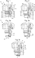
- This control rod allows the wearer to perform different commands depending on the axial position of the cover 11 relative to the tube 20, for example the winding of the watch when the hood 11 is in a first axial position as illustrated by the figure 1 , or some corrections, such as that of the time, when the cover 11 is in a second axial position as illustrated by the figure 2 .
- the piston 32 and the spring 34 are also involved in regulating the pressure inside the watch case by means of a safety valve, a detailed description of which is given below.
- the piston and the spring thus form an assembly which has the advantage of being involved in the realization of two main functions which are independent of one another, namely: the activation of the control rod to perform different adjustments on the one hand, and the regulation of the pressure inside the watch case on the other hand.
- the crown head 10 comprises locking means preventing the disengagement between the cover 11 and the tube 20.
- the locking means comprise a shoulder 21b arranged on the inner wall 21 of the tube 20 and having a bearing surface against which a portion of the piston 32 can abut.
- the locking means also comprise a flange 23a provided at the base of the central barrel 23 and arranged to abut against the shoulder 32a provided on the piston 32.
- the portion of the piston 32 that can abut against the shoulder 21b of the tube 20 is formed by the head 33a of a guide screw 33 integral with the piston 32.
- the piston 32 comprises a tapping in which the guide screw 33 is screwed.
- the guide screw 33 also comprises a cone-shaped recessed central portion 33b and a peripheral annular portion 33c that extends as far as the inner wall 21 of the tube 20.
- the peripheral annular portion 33c of the head 33a of the guide screw 33 is arranged to abut against this shoulder 21b of the tube 20 when the cover 11 is brought into its second axial position.
- the flange 23a at the base of the central barrel 23 is arranged to engage in a notch 32c provided for this purpose under the underside of the shoulder 32a of the piston 32 when said flange 23a abuts against the lower face of the shoulder 32a of the piston 32.
- a safety valve is integrated in the crown head.
- the safety valve has an evacuation channel arranged to be in fluid communication with the interior of the watch case when the valve is in an open configuration to remove excess pressure in the case.
- the valve comprises a pressure regulator arranged inside the evacuation channel to control the output velocity of a fluid which is in the form of a gas, preferably helium.
- the pressure regulator comprises for this purpose a ball 35 cooperating with a ball seat 37 mounted at the inlet 30 of the discharge channel.
- the ball seat 37, the tube 20 and the axial skirt 13 have a symmetry of revolution with respect to the axis of rotation A of the cover 11.
- the ball and its seat may for example be based on metal, ceramic or ceramic. thermoplastic materials among others.
- the seat 37 comprises an annular base 37a having an opening whose axis of revolution coincides with the axis of rotation A of the cover 11. The diameter of this opening is smaller than the diameter of the ball 35. This opening corresponds to the entry 30 of the discharge channel of the valve.
- the seat 37 also comprises a support surface 37b inclined and circular intended to be in contact with the ball 35, a cylindrical wall 37d to ensure the centering of the ball 35 with respect to the axis of rotation A of the cover 11 and a peripheral bearing surface 37c arranged opposite the peripheral annular portion 33c of the head 33a of the guide screw 33 .
- the head 33a of the guide screw 33 is arranged facing the ball 35.
- the configuration and positioning of the guide screw 33 and the seat 37 form a cage defining a space in which the ball 35 can move under the effect of pressure.
- the ball 35 is arranged on its seat 37 so as to obstruct the passage of the gas in the discharge channel when the pressure in the watch case, upstream of the ball, is lower than a predetermined value.
- This value can be adapted to the circumstances, this adaptation being achieved by the choice of the compression spring 34 which maintains one end of the piston 32 bearing against the ball 35.
- the properties of the spring 34 are therefore chosen to handle the stress exerted by the piston 32 on the ball 35 to control the opening pressure of the valve. Note that the ball is always under the stress of the spring 34 when the crown head 10 is in a screwed configuration ( figure 1 ) while the spring 34 is adjusted so that the ball 35 is free or slightly stressed when the crown head 10 is in an unscrewed configuration ( figure 2 ).
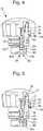
- the crown head 10 is in a unscrewed configuration while the pressure inside the watch case exceeds a critical threshold. Under the effect of this excessive pressure, the ball 35 is dislodged from its seat 37 which allows the gas to access the inlet 30 of the discharge channel ( figure 3a ), then move along this channel ( figure 3b ) to the exit 31 of the canal ( figure 3c ) to allow the evacuation of the gas out of the valve.
- the safety valve comprises a membrane 40 arranged to be permeable to gases and establish fluid communication from the inside of the housing to the outside when said internal pressure exceeds a predetermined value and impervious to liquids flowing from outside the housing to the inside of the housing.
- a membrane support 42 is mounted at the inlet 30 of the discharge channel, inside the base of the tube 20.
- the membrane support 42 comprises an annular base 42a on which the edge of the membrane 40 and having an opening whose axis of revolution coincides with the axis of rotation A of the cover 11. This opening corresponds to the inlet 30 of the discharge channel of the valve.
- the membrane support 42 also comprises a shoulder ring 42b arranged to clamp the membrane 40 against the base 42a and whose shoulder 42c is disposed opposite the peripheral annular portion 33c of the head 33a of the guide screw 33.
- a set is provided between the shoulder 42c and the peripheral annular portion 33a to form a portion of the discharge channel.
- the membrane is for example composed of a waterproof polymer film permeable to gas. Typically the polymer film is carried by a porous gas substrate.
- this membrane may be a membrane sold by Gore under the reference "Acoustic wind GAW331".
- the gas comes into contact with the membrane 40 which is permeable to gases, which allows the gas to pass through it, and move along the discharge channel formed by the various elements in the crown head to the outlet 31 of the channel to allow the evacuation of the gas out of the valve.
- the piston may be in one piece or consist of several parts assembled.
Landscapes
- Physics & Mathematics (AREA)
- General Physics & Mathematics (AREA)
- Engineering & Computer Science (AREA)
- General Engineering & Computer Science (AREA)
- Mechanical Engineering (AREA)
- Safety Valves (AREA)
Priority Applications (5)
| Application Number | Priority Date | Filing Date | Title |
|---|---|---|---|
| EP17182439.4A EP3432086B1 (de) | 2017-07-20 | 2017-07-20 | Sicherheitsventil für uhr |
| US16/035,928 US10871748B2 (en) | 2017-07-20 | 2018-07-16 | Safety valve for a timepiece |
| JP2018133940A JP6666962B2 (ja) | 2017-07-20 | 2018-07-17 | 時計用安全バルブ |
| KR1020180083709A KR102059748B1 (ko) | 2017-07-20 | 2018-07-18 | 타임피스용 안전 밸브 |
| CN201810794891.0A CN109283827B (zh) | 2017-07-20 | 2018-07-19 | 用于钟表的安全阀 |
Applications Claiming Priority (1)
| Application Number | Priority Date | Filing Date | Title |
|---|---|---|---|
| EP17182439.4A EP3432086B1 (de) | 2017-07-20 | 2017-07-20 | Sicherheitsventil für uhr |
Publications (2)
| Publication Number | Publication Date |
|---|---|
| EP3432086A1 true EP3432086A1 (de) | 2019-01-23 |
| EP3432086B1 EP3432086B1 (de) | 2020-04-15 |
Family
ID=59383514
Family Applications (1)
| Application Number | Title | Priority Date | Filing Date |
|---|---|---|---|
| EP17182439.4A Active EP3432086B1 (de) | 2017-07-20 | 2017-07-20 | Sicherheitsventil für uhr |
Country Status (5)
| Country | Link |
|---|---|
| US (1) | US10871748B2 (de) |
| EP (1) | EP3432086B1 (de) |
| JP (1) | JP6666962B2 (de) |
| KR (1) | KR102059748B1 (de) |
| CN (1) | CN109283827B (de) |
Cited By (1)
| Publication number | Priority date | Publication date | Assignee | Title |
|---|---|---|---|---|
| CN114545755A (zh) * | 2020-11-25 | 2022-05-27 | 梅科股份公司 | 用于时计的表冠按钮 |
Families Citing this family (7)
| Publication number | Priority date | Publication date | Assignee | Title |
|---|---|---|---|---|
| EP3432085B1 (de) * | 2017-07-20 | 2020-04-15 | Meco S.A. | Sicherheitsventil für uhr |
| EP3742235B1 (de) * | 2019-05-23 | 2022-01-26 | Meco S.A. | Druckknopfsystem und dieses umfassende uhr |
| EP3805869B1 (de) * | 2019-10-09 | 2025-12-24 | Meco S.A. | Geschraubte krone |
| CN112213940B (zh) * | 2020-09-30 | 2021-09-28 | 西安易朴通讯技术有限公司 | 可穿戴设备 |
| KR102770785B1 (ko) | 2021-12-27 | 2025-02-21 | 이태웅 | 세라믹 손목 시계 |
| KR20240110347A (ko) | 2023-01-06 | 2024-07-15 | 이광호 | 방수 및 방진 겸용 패킹을 구비하는 세라믹 손목 시계 |
| KR20240131692A (ko) | 2023-02-24 | 2024-09-02 | 이태웅 | 세라믹 손목 시계 |
Citations (3)
| Publication number | Priority date | Publication date | Assignee | Title |
|---|---|---|---|---|
| JPS5491150U (de) * | 1977-12-08 | 1979-06-27 | ||
| EP0556155A1 (de) * | 1992-02-12 | 1993-08-18 | Montres Rolex Sa | Wasserdichte Steuerungsvorrichtung für Uhren |
| CH703455A1 (fr) * | 2010-07-17 | 2012-01-31 | Pibor Iso S A | Couronne et procede d'activation d'une telle couronne sur une boîte de montre. |
Family Cites Families (18)
| Publication number | Priority date | Publication date | Assignee | Title |
|---|---|---|---|---|
| CH624259B (fr) * | 1979-03-29 | Boninchi Sa | Poussoir etanche pour montre de plongee. | |
| CH682199B5 (fr) * | 1992-02-07 | 1994-02-15 | Smh Management Services Ag | Soupape de sécurité pour pièce d'horlogérie de plongeur. |
| CH691936A5 (de) * | 1997-06-11 | 2001-11-30 | Meco Sa Grenchen | Betätigungsmittel mit Dichtung für eine Uhr. |
| CH691935A5 (de) * | 1997-06-11 | 2001-11-30 | Meco Sa Grenchen | Sicherheitsventil für eine Uhr. |
| JP2003240877A (ja) * | 2002-02-14 | 2003-08-27 | Citizen Watch Co Ltd | 排気バルブ |
| ATE431579T1 (de) * | 2004-02-10 | 2009-05-15 | Tissot Sa | Vorrichtung zum kroneschütz für eine uhr |
| JP4619815B2 (ja) * | 2005-02-21 | 2011-01-26 | セイコーインスツル株式会社 | 携帯時計及びこの時計に用いる竜頭 |
| JP5279661B2 (ja) * | 2009-08-28 | 2013-09-04 | セイコーインスツル株式会社 | 携帯時計 |
| JP5405945B2 (ja) * | 2009-08-28 | 2014-02-05 | セイコーインスツル株式会社 | 携帯時計 |
| EP2607972B1 (de) * | 2011-12-22 | 2016-04-27 | The Swatch Group Research and Development Ltd. | Dichter Druckknopf für Armbanduhr |
| EP2685327B1 (de) * | 2012-07-09 | 2018-09-05 | Omega SA | Druckstößel für eine Uhr, das ein Ventil enthält |
| CH707525B1 (fr) * | 2013-01-24 | 2017-06-30 | Prétat Roland | Mécanisme de réglage pour montre. |
| JP6132162B2 (ja) * | 2014-03-24 | 2017-05-24 | カシオ計算機株式会社 | 計時装置および腕時計 |
| JP2015230270A (ja) * | 2014-06-06 | 2015-12-21 | カシオ計算機株式会社 | 押釦構造および時計 |
| EP3287855B1 (de) * | 2016-08-26 | 2019-05-01 | Meco S.A. | Einstellkrone für uhr |
| EP3432085B1 (de) * | 2017-07-20 | 2020-04-15 | Meco S.A. | Sicherheitsventil für uhr |
| EP3483669B1 (de) * | 2017-11-08 | 2020-12-30 | Omega SA | Sicherheitsventil für armbanduhr |
| EP3483670B1 (de) * | 2017-11-08 | 2020-07-29 | Omega SA | Sicherheitsventil für armbanduhr |
-
2017
- 2017-07-20 EP EP17182439.4A patent/EP3432086B1/de active Active
-
2018
- 2018-07-16 US US16/035,928 patent/US10871748B2/en active Active
- 2018-07-17 JP JP2018133940A patent/JP6666962B2/ja active Active
- 2018-07-18 KR KR1020180083709A patent/KR102059748B1/ko active Active
- 2018-07-19 CN CN201810794891.0A patent/CN109283827B/zh active Active
Patent Citations (3)
| Publication number | Priority date | Publication date | Assignee | Title |
|---|---|---|---|---|
| JPS5491150U (de) * | 1977-12-08 | 1979-06-27 | ||
| EP0556155A1 (de) * | 1992-02-12 | 1993-08-18 | Montres Rolex Sa | Wasserdichte Steuerungsvorrichtung für Uhren |
| CH703455A1 (fr) * | 2010-07-17 | 2012-01-31 | Pibor Iso S A | Couronne et procede d'activation d'une telle couronne sur une boîte de montre. |
Cited By (1)
| Publication number | Priority date | Publication date | Assignee | Title |
|---|---|---|---|---|
| CN114545755A (zh) * | 2020-11-25 | 2022-05-27 | 梅科股份公司 | 用于时计的表冠按钮 |
Also Published As
| Publication number | Publication date |
|---|---|
| EP3432086B1 (de) | 2020-04-15 |
| US10871748B2 (en) | 2020-12-22 |
| KR20190010464A (ko) | 2019-01-30 |
| CN109283827A (zh) | 2019-01-29 |
| JP6666962B2 (ja) | 2020-03-18 |
| KR102059748B1 (ko) | 2019-12-26 |
| CN109283827B (zh) | 2020-11-27 |
| US20190025764A1 (en) | 2019-01-24 |
| JP2019020414A (ja) | 2019-02-07 |
Similar Documents
| Publication | Publication Date | Title |
|---|---|---|
| EP3432086B1 (de) | Sicherheitsventil für uhr | |
| EP3432085B1 (de) | Sicherheitsventil für uhr | |
| EP3483669B1 (de) | Sicherheitsventil für armbanduhr | |
| EP3287855B1 (de) | Einstellkrone für uhr | |
| EP3483670B1 (de) | Sicherheitsventil für armbanduhr | |
| CH714005A2 (fr) | Tête couronne comprenant une soupape de sécurité pour pièce d'horlogerie. | |
| EP2870516A1 (de) | Druckmindererventil mit darin eingebauter restdruckfunktion | |
| CH707293A2 (fr) | Couronne démontable. | |
| FR2796543A1 (fr) | Soupape de securite pour un autocuiseur a trou d'homme | |
| EP3428740B1 (de) | Sicherheitsventil für armbanduhr | |
| EP3432084B1 (de) | Sicherheitsventil für armbanduhr | |
| EP2639486A1 (de) | Verschlussvorrichtung und -verfahren | |
| EP3428741B1 (de) | Sicherheitsventil für armbanduhr | |
| FR2615583A1 (fr) | Valve de surpression reglable pour elements gonflables sous-marins dotee d'une impermeabilite absolue et concue rationnellement pour des couts de production reduits | |
| EP1975749B1 (de) | Uhr mit elastisch gehaltenem Uhrwerk | |
| CH714006A2 (fr) | Soupape de sécurité, tête couronne et pièce d'horlogerie. | |
| EP0611219A1 (de) | Patronenartiges Membran-Sicherheitsventil mit modularen Aufbau | |
| EP4206827B1 (de) | Sicherheitsventil für armbanduhr | |
| CH331280A (fr) | Couronne étanche pour appareil de mesure, notamment pour montre | |
| EP1205826A1 (de) | Einstellvorrichtung für eine Uhr vom angeschraubten Krone Typ | |
| CH714309A2 (fr) | Soupape de sécurité pour montre. | |
| CH346176A (fr) | Couronne de remontoir étanche | |
| CH720145A2 (fr) | Couronne de réglage pour pièce d'horlogerie. | |
| CH714310A2 (fr) | Soupape de sécurité pour montre. | |
| CH705590A2 (fr) | Dispositif de commande pour mouvement horloger. |
Legal Events
| Date | Code | Title | Description |
|---|---|---|---|
| PUAI | Public reference made under article 153(3) epc to a published international application that has entered the european phase |
Free format text: ORIGINAL CODE: 0009012 |
|
| STAA | Information on the status of an ep patent application or granted ep patent |
Free format text: STATUS: THE APPLICATION HAS BEEN PUBLISHED |
|
| AK | Designated contracting states |
Kind code of ref document: A1 Designated state(s): AL AT BE BG CH CY CZ DE DK EE ES FI FR GB GR HR HU IE IS IT LI LT LU LV MC MK MT NL NO PL PT RO RS SE SI SK SM TR |
|
| AX | Request for extension of the european patent |
Extension state: BA ME |
|
| STAA | Information on the status of an ep patent application or granted ep patent |
Free format text: STATUS: REQUEST FOR EXAMINATION WAS MADE |
|
| RBV | Designated contracting states (corrected) |
Designated state(s): AL AT BE BG CH CY CZ DE DK EE ES FI FR GB GR HR HU IE IS IT LI LT LU LV MC MK MT NL NO PL PT RO RS SE SI SK SM TR |
|
| 17P | Request for examination filed |
Effective date: 20190726 |
|
| GRAP | Despatch of communication of intention to grant a patent |
Free format text: ORIGINAL CODE: EPIDOSNIGR1 |
|
| STAA | Information on the status of an ep patent application or granted ep patent |
Free format text: STATUS: GRANT OF PATENT IS INTENDED |
|
| INTG | Intention to grant announced |
Effective date: 20191213 |
|
| GRAS | Grant fee paid |
Free format text: ORIGINAL CODE: EPIDOSNIGR3 |
|
| GRAA | (expected) grant |
Free format text: ORIGINAL CODE: 0009210 |
|
| STAA | Information on the status of an ep patent application or granted ep patent |
Free format text: STATUS: THE PATENT HAS BEEN GRANTED |
|
| AK | Designated contracting states |
Kind code of ref document: B1 Designated state(s): AL AT BE BG CH CY CZ DE DK EE ES FI FR GB GR HR HU IE IS IT LI LT LU LV MC MK MT NL NO PL PT RO RS SE SI SK SM TR |
|
| REG | Reference to a national code |
Ref country code: CH Ref legal event code: EP |
|
| REG | Reference to a national code |
Ref country code: CH Ref legal event code: NV Representative=s name: ICB INGENIEURS CONSEILS EN BREVETS SA, CH |
|
| REG | Reference to a national code |
Ref country code: DE Ref legal event code: R096 Ref document number: 602017014666 Country of ref document: DE |
|
| REG | Reference to a national code |
Ref country code: IE Ref legal event code: FG4D Free format text: LANGUAGE OF EP DOCUMENT: FRENCH |
|
| REG | Reference to a national code |
Ref country code: AT Ref legal event code: REF Ref document number: 1258038 Country of ref document: AT Kind code of ref document: T Effective date: 20200515 |
|
| REG | Reference to a national code |
Ref country code: NL Ref legal event code: MP Effective date: 20200415 |
|
| REG | Reference to a national code |
Ref country code: LT Ref legal event code: MG4D |
|
| PG25 | Lapsed in a contracting state [announced via postgrant information from national office to epo] |
Ref country code: IS Free format text: LAPSE BECAUSE OF FAILURE TO SUBMIT A TRANSLATION OF THE DESCRIPTION OR TO PAY THE FEE WITHIN THE PRESCRIBED TIME-LIMIT Effective date: 20200815 Ref country code: GR Free format text: LAPSE BECAUSE OF FAILURE TO SUBMIT A TRANSLATION OF THE DESCRIPTION OR TO PAY THE FEE WITHIN THE PRESCRIBED TIME-LIMIT Effective date: 20200716 Ref country code: NO Free format text: LAPSE BECAUSE OF FAILURE TO SUBMIT A TRANSLATION OF THE DESCRIPTION OR TO PAY THE FEE WITHIN THE PRESCRIBED TIME-LIMIT Effective date: 20200715 Ref country code: FI Free format text: LAPSE BECAUSE OF FAILURE TO SUBMIT A TRANSLATION OF THE DESCRIPTION OR TO PAY THE FEE WITHIN THE PRESCRIBED TIME-LIMIT Effective date: 20200415 Ref country code: NL Free format text: LAPSE BECAUSE OF FAILURE TO SUBMIT A TRANSLATION OF THE DESCRIPTION OR TO PAY THE FEE WITHIN THE PRESCRIBED TIME-LIMIT Effective date: 20200415 Ref country code: SE Free format text: LAPSE BECAUSE OF FAILURE TO SUBMIT A TRANSLATION OF THE DESCRIPTION OR TO PAY THE FEE WITHIN THE PRESCRIBED TIME-LIMIT Effective date: 20200415 Ref country code: PT Free format text: LAPSE BECAUSE OF FAILURE TO SUBMIT A TRANSLATION OF THE DESCRIPTION OR TO PAY THE FEE WITHIN THE PRESCRIBED TIME-LIMIT Effective date: 20200817 Ref country code: LT Free format text: LAPSE BECAUSE OF FAILURE TO SUBMIT A TRANSLATION OF THE DESCRIPTION OR TO PAY THE FEE WITHIN THE PRESCRIBED TIME-LIMIT Effective date: 20200415 |
|
| REG | Reference to a national code |
Ref country code: AT Ref legal event code: MK05 Ref document number: 1258038 Country of ref document: AT Kind code of ref document: T Effective date: 20200415 |
|
| PG25 | Lapsed in a contracting state [announced via postgrant information from national office to epo] |
Ref country code: BG Free format text: LAPSE BECAUSE OF FAILURE TO SUBMIT A TRANSLATION OF THE DESCRIPTION OR TO PAY THE FEE WITHIN THE PRESCRIBED TIME-LIMIT Effective date: 20200715 Ref country code: RS Free format text: LAPSE BECAUSE OF FAILURE TO SUBMIT A TRANSLATION OF THE DESCRIPTION OR TO PAY THE FEE WITHIN THE PRESCRIBED TIME-LIMIT Effective date: 20200415 Ref country code: LV Free format text: LAPSE BECAUSE OF FAILURE TO SUBMIT A TRANSLATION OF THE DESCRIPTION OR TO PAY THE FEE WITHIN THE PRESCRIBED TIME-LIMIT Effective date: 20200415 Ref country code: HR Free format text: LAPSE BECAUSE OF FAILURE TO SUBMIT A TRANSLATION OF THE DESCRIPTION OR TO PAY THE FEE WITHIN THE PRESCRIBED TIME-LIMIT Effective date: 20200415 |
|
| PG25 | Lapsed in a contracting state [announced via postgrant information from national office to epo] |
Ref country code: AL Free format text: LAPSE BECAUSE OF FAILURE TO SUBMIT A TRANSLATION OF THE DESCRIPTION OR TO PAY THE FEE WITHIN THE PRESCRIBED TIME-LIMIT Effective date: 20200415 |
|
| REG | Reference to a national code |
Ref country code: DE Ref legal event code: R097 Ref document number: 602017014666 Country of ref document: DE |
|
| PG25 | Lapsed in a contracting state [announced via postgrant information from national office to epo] |
Ref country code: AT Free format text: LAPSE BECAUSE OF FAILURE TO SUBMIT A TRANSLATION OF THE DESCRIPTION OR TO PAY THE FEE WITHIN THE PRESCRIBED TIME-LIMIT Effective date: 20200415 Ref country code: DK Free format text: LAPSE BECAUSE OF FAILURE TO SUBMIT A TRANSLATION OF THE DESCRIPTION OR TO PAY THE FEE WITHIN THE PRESCRIBED TIME-LIMIT Effective date: 20200415 Ref country code: EE Free format text: LAPSE BECAUSE OF FAILURE TO SUBMIT A TRANSLATION OF THE DESCRIPTION OR TO PAY THE FEE WITHIN THE PRESCRIBED TIME-LIMIT Effective date: 20200415 Ref country code: SM Free format text: LAPSE BECAUSE OF FAILURE TO SUBMIT A TRANSLATION OF THE DESCRIPTION OR TO PAY THE FEE WITHIN THE PRESCRIBED TIME-LIMIT Effective date: 20200415 Ref country code: CZ Free format text: LAPSE BECAUSE OF FAILURE TO SUBMIT A TRANSLATION OF THE DESCRIPTION OR TO PAY THE FEE WITHIN THE PRESCRIBED TIME-LIMIT Effective date: 20200415 Ref country code: IT Free format text: LAPSE BECAUSE OF FAILURE TO SUBMIT A TRANSLATION OF THE DESCRIPTION OR TO PAY THE FEE WITHIN THE PRESCRIBED TIME-LIMIT Effective date: 20200415 Ref country code: RO Free format text: LAPSE BECAUSE OF FAILURE TO SUBMIT A TRANSLATION OF THE DESCRIPTION OR TO PAY THE FEE WITHIN THE PRESCRIBED TIME-LIMIT Effective date: 20200415 Ref country code: ES Free format text: LAPSE BECAUSE OF FAILURE TO SUBMIT A TRANSLATION OF THE DESCRIPTION OR TO PAY THE FEE WITHIN THE PRESCRIBED TIME-LIMIT Effective date: 20200415 |
|
| REG | Reference to a national code |
Ref country code: DE Ref legal event code: R119 Ref document number: 602017014666 Country of ref document: DE |
|
| PLBE | No opposition filed within time limit |
Free format text: ORIGINAL CODE: 0009261 |
|
| STAA | Information on the status of an ep patent application or granted ep patent |
Free format text: STATUS: NO OPPOSITION FILED WITHIN TIME LIMIT |
|
| PG25 | Lapsed in a contracting state [announced via postgrant information from national office to epo] |
Ref country code: MC Free format text: LAPSE BECAUSE OF FAILURE TO SUBMIT A TRANSLATION OF THE DESCRIPTION OR TO PAY THE FEE WITHIN THE PRESCRIBED TIME-LIMIT Effective date: 20200415 Ref country code: PL Free format text: LAPSE BECAUSE OF FAILURE TO SUBMIT A TRANSLATION OF THE DESCRIPTION OR TO PAY THE FEE WITHIN THE PRESCRIBED TIME-LIMIT Effective date: 20200415 Ref country code: SK Free format text: LAPSE BECAUSE OF FAILURE TO SUBMIT A TRANSLATION OF THE DESCRIPTION OR TO PAY THE FEE WITHIN THE PRESCRIBED TIME-LIMIT Effective date: 20200415 |
|
| 26N | No opposition filed |
Effective date: 20210118 |
|
| REG | Reference to a national code |
Ref country code: BE Ref legal event code: MM Effective date: 20200731 |
|
| PG25 | Lapsed in a contracting state [announced via postgrant information from national office to epo] |
Ref country code: LU Free format text: LAPSE BECAUSE OF NON-PAYMENT OF DUE FEES Effective date: 20200720 |
|
| PG25 | Lapsed in a contracting state [announced via postgrant information from national office to epo] |
Ref country code: BE Free format text: LAPSE BECAUSE OF NON-PAYMENT OF DUE FEES Effective date: 20200731 Ref country code: DE Free format text: LAPSE BECAUSE OF NON-PAYMENT OF DUE FEES Effective date: 20210202 Ref country code: SI Free format text: LAPSE BECAUSE OF FAILURE TO SUBMIT A TRANSLATION OF THE DESCRIPTION OR TO PAY THE FEE WITHIN THE PRESCRIBED TIME-LIMIT Effective date: 20200415 |
|
| PG25 | Lapsed in a contracting state [announced via postgrant information from national office to epo] |
Ref country code: IE Free format text: LAPSE BECAUSE OF NON-PAYMENT OF DUE FEES Effective date: 20200720 |
|
| GBPC | Gb: european patent ceased through non-payment of renewal fee |
Effective date: 20210720 |
|
| PG25 | Lapsed in a contracting state [announced via postgrant information from national office to epo] |
Ref country code: GB Free format text: LAPSE BECAUSE OF NON-PAYMENT OF DUE FEES Effective date: 20210720 |
|
| PG25 | Lapsed in a contracting state [announced via postgrant information from national office to epo] |
Ref country code: TR Free format text: LAPSE BECAUSE OF FAILURE TO SUBMIT A TRANSLATION OF THE DESCRIPTION OR TO PAY THE FEE WITHIN THE PRESCRIBED TIME-LIMIT Effective date: 20200415 Ref country code: MT Free format text: LAPSE BECAUSE OF FAILURE TO SUBMIT A TRANSLATION OF THE DESCRIPTION OR TO PAY THE FEE WITHIN THE PRESCRIBED TIME-LIMIT Effective date: 20200415 Ref country code: CY Free format text: LAPSE BECAUSE OF FAILURE TO SUBMIT A TRANSLATION OF THE DESCRIPTION OR TO PAY THE FEE WITHIN THE PRESCRIBED TIME-LIMIT Effective date: 20200415 |
|
| PG25 | Lapsed in a contracting state [announced via postgrant information from national office to epo] |
Ref country code: MK Free format text: LAPSE BECAUSE OF FAILURE TO SUBMIT A TRANSLATION OF THE DESCRIPTION OR TO PAY THE FEE WITHIN THE PRESCRIBED TIME-LIMIT Effective date: 20200415 |
|
| P01 | Opt-out of the competence of the unified patent court (upc) registered |
Effective date: 20230719 |
|
| PGFP | Annual fee paid to national office [announced via postgrant information from national office to epo] |
Ref country code: FR Payment date: 20250620 Year of fee payment: 9 |
|
| PGFP | Annual fee paid to national office [announced via postgrant information from national office to epo] |
Ref country code: CH Payment date: 20250801 Year of fee payment: 9 |