EP3432086A1 - Safety valve for a timepiece - Google Patents
Safety valve for a timepiece Download PDFInfo
- Publication number
- EP3432086A1 EP3432086A1 EP17182439.4A EP17182439A EP3432086A1 EP 3432086 A1 EP3432086 A1 EP 3432086A1 EP 17182439 A EP17182439 A EP 17182439A EP 3432086 A1 EP3432086 A1 EP 3432086A1
- Authority
- EP
- European Patent Office
- Prior art keywords
- tube
- piston
- crown head
- ball
- cover
- Prior art date
- Legal status (The legal status is an assumption and is not a legal conclusion. Google has not performed a legal analysis and makes no representation as to the accuracy of the status listed.)
- Granted
Links
Images
Classifications
-
- G—PHYSICS
- G04—HOROLOGY
- G04B—MECHANICALLY-DRIVEN CLOCKS OR WATCHES; MECHANICAL PARTS OF CLOCKS OR WATCHES IN GENERAL; TIME PIECES USING THE POSITION OF THE SUN, MOON OR STARS
- G04B3/00—Normal winding of clockworks by hand or mechanically; Winding up several mainsprings or driving weights simultaneously
- G04B3/04—Rigidly-mounted keys, knobs or crowns
- G04B3/041—Construction of crowns for rotating movement; connection with the winding stem; winding stems
-
- G—PHYSICS
- G04—HOROLOGY
- G04B—MECHANICALLY-DRIVEN CLOCKS OR WATCHES; MECHANICAL PARTS OF CLOCKS OR WATCHES IN GENERAL; TIME PIECES USING THE POSITION OF THE SUN, MOON OR STARS
- G04B37/00—Cases
- G04B37/08—Hermetic sealing of openings, joints, passages or slits
- G04B37/10—Hermetic sealing of openings, joints, passages or slits of winding stems
- G04B37/103—Hermetic sealing of openings, joints, passages or slits of winding stems by screwing the crown onto the case
-
- G—PHYSICS
- G04—HOROLOGY
- G04B—MECHANICALLY-DRIVEN CLOCKS OR WATCHES; MECHANICAL PARTS OF CLOCKS OR WATCHES IN GENERAL; TIME PIECES USING THE POSITION OF THE SUN, MOON OR STARS
- G04B37/00—Cases
- G04B37/08—Hermetic sealing of openings, joints, passages or slits
- G04B37/10—Hermetic sealing of openings, joints, passages or slits of winding stems
-
- F—MECHANICAL ENGINEERING; LIGHTING; HEATING; WEAPONS; BLASTING
- F16—ENGINEERING ELEMENTS AND UNITS; GENERAL MEASURES FOR PRODUCING AND MAINTAINING EFFECTIVE FUNCTIONING OF MACHINES OR INSTALLATIONS; THERMAL INSULATION IN GENERAL
- F16K—VALVES; TAPS; COCKS; ACTUATING-FLOATS; DEVICES FOR VENTING OR AERATING
- F16K17/00—Safety valves; Equalising valves, e.g. pressure relief valves
- F16K17/02—Safety valves; Equalising valves, e.g. pressure relief valves opening on surplus pressure on one side; closing on insufficient pressure on one side
- F16K17/04—Safety valves; Equalising valves, e.g. pressure relief valves opening on surplus pressure on one side; closing on insufficient pressure on one side spring-loaded
- F16K17/06—Safety valves; Equalising valves, e.g. pressure relief valves opening on surplus pressure on one side; closing on insufficient pressure on one side spring-loaded with special arrangements for adjusting the opening pressure
-
- G—PHYSICS
- G04—HOROLOGY
- G04B—MECHANICALLY-DRIVEN CLOCKS OR WATCHES; MECHANICAL PARTS OF CLOCKS OR WATCHES IN GENERAL; TIME PIECES USING THE POSITION OF THE SUN, MOON OR STARS
- G04B37/00—Cases
- G04B37/02—Evacuated cases; Cases filled with gas or liquids; Cases containing substances for absorbing or binding moisture or dust
Definitions
- the present invention relates to a safety valve configured to be integrated into a crown head of a timepiece.
- This type of valve is particularly well suited for diving watches.
- a watch case with a crown head comprising a valve to allow either to blow a gas into the box, in order to reign inside thereof a pressure greater than the ambient pressure, preventing the penetration of water, steam or dust into the box, or on the contrary to evacuate the interior of the box in order to remove the movement from the effects of the air contained in the box. box when closed.
- Such crown head in screwed position, ensures a reinforced seal of the timepiece.
- the crown head In the unscrewed position, the crown head is in an open configuration and makes it possible to evacuate an excess of fluid.
- the crown head can also take different axial positions, each axial position to achieve a setting mode.
- An object of the present invention is therefore to provide a crown head preventing the complete unscrewing of its cover.
- a crown head for a timepiece especially for a diving watch, comprising a cover comprising a cover and an axial skirt, a tube intended to be fixed in a case of the timepiece, a seal located between the tube and the axial skirt, and a central barrel arranged to be engaged with the tube.
- the central barrel and the cover form an assembly that can be placed in different axial positions with respect to the tube.
- the crown head further comprises a safety valve having an evacuation channel arranged to be in fluid communication with the interior of the housing when the valve is in an open configuration to discharge an excess of fluid, said safety valve further comprising a piston mounted within the central barrel and an elastic member arranged to cooperate with the piston, which is configured to move axially according to the pressure variations within the housing.
- the crown head further comprises locking means preventing the separation between the cover and the tube.
- the locking means comprise a shoulder arranged on the inner wall of the tube and having a bearing surface against which a portion of the piston can abut and a rim provided at the base of the central barrel and arranged to come in abutment against a shoulder provided on the piston.
- the portion of the piston that can abut against the shoulder of the tube is formed by a head of a guide screw secured to the piston.
- the safety valve may furthermore comprise a pressure regulator arranged inside the evacuation channel to control the output velocity of the fluid.
- the pressure regulator comprises a ball arranged to cooperate with a ball seat.
- This ball is arranged on the ball seat so as to obstruct the passage of a fluid in the discharge channel when the internal pressure upstream of the ball is less than a predetermined value.
- the ball is dislodged from its seat when said internal pressure exceeds the predetermined value to establish said fluid communication.
- the ball seat, the tube and the axial skirt have a symmetry of revolution relative to the axis of rotation (A) of the cover.
- the seat has a central opening corresponding to the entrance of the evacuation channel and a bearing surface intended to be in contact with the ball.
- the safety valve may furthermore comprise a membrane arranged to be permeable to gases and establish fluid communication from the inside of the housing to the outside when said internal pressure exceeds a predetermined value and is impermeable to liquids. flowing from the outside of the case towards the inside of the case.
- the piston and the elastic member form an assembly arranged on the one hand to actuate the movement of a control rod, and on the other hand, for the regulation of the pressure inside. of the case.
- the present invention also relates to a timepiece, in particular a diving watch, comprising at least the adjusting crown head as defined above.
- the crown head 10 comprises a tube 20 intended to be fixed on a watch case (not shown) by screwing or driving in the middle of the case.
- the tube 20 has a threaded portion 21a disposed on its inner wall 21 and a bulge 22a disposed along the circumference of its outer wall 22.
- the crown head 10 also comprises a cover 11, which comprises a cover 12 and a axial skirt 13 having a symmetry of revolution about the axis of rotation A of the cover 11.
- the cover 12 and the axial skirt 13 of the cover 11 define a cavity 15 in the cover 11.
- the crown head 10 further comprises a central barrel 23 arranged in the cavity 15 of the cover 11 and secured thereto.
- the central barrel 23 has on its outer wall 25 a threaded portion 25a screwed into the threaded portion 21a of the tube 20.
- the adjusting ring head 10 further comprises a seal 17 interposed between the axial skirt 13 of the cover 11 and the tube 20 so as to ensure the sealing of the crown head regardless of whether the cover 11 is in a first axial position in which the crown head is screwed or in a second axial position in which the crown head is unscrewed.
- this seal 17 is an O-ring.
- This seal 17 is arranged between circular shoulder 14 formed in the axial skirt 13 and a ring-shaped holding ring 18.
- This ring 18 is fixed, for example by driving, in a groove 16 of corresponding shape located towards the base of the axial skirt 13 facing the tube 20.
- the seal 17 is overcompressed by the bulge 22a of the tube 20 so that the sealing properties are the best possible when the cover 11 is in the first axial position in which the crown head 10 is in a configuration called screwed.
- the adjusting crown head 10 also comprises a piston 32 housed in a central opening of the central barrel 23 as well as an elastic member, for example a compression spring 34 of the helical type, in a cavity defined by the bonnet-barrel assembly. on the one hand and by the piston 32 on the other hand.
- the spring 34 is compressed axially between the cover 12 of the cover 11 and a shoulder 32a of the piston 32, and it makes it possible, in particular, to move the cover 11 away from the shoulder of the piston 32.
- the piston 32 kinematically connects the cover 11 to a rod of control (not shown) of the watch movement housed in the watch case.
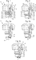
- This control rod allows the wearer to perform different commands depending on the axial position of the cover 11 relative to the tube 20, for example the winding of the watch when the hood 11 is in a first axial position as illustrated by the figure 1 , or some corrections, such as that of the time, when the cover 11 is in a second axial position as illustrated by the figure 2 .
- the piston 32 and the spring 34 are also involved in regulating the pressure inside the watch case by means of a safety valve, a detailed description of which is given below.
- the piston and the spring thus form an assembly which has the advantage of being involved in the realization of two main functions which are independent of one another, namely: the activation of the control rod to perform different adjustments on the one hand, and the regulation of the pressure inside the watch case on the other hand.
- the crown head 10 comprises locking means preventing the disengagement between the cover 11 and the tube 20.
- the locking means comprise a shoulder 21b arranged on the inner wall 21 of the tube 20 and having a bearing surface against which a portion of the piston 32 can abut.
- the locking means also comprise a flange 23a provided at the base of the central barrel 23 and arranged to abut against the shoulder 32a provided on the piston 32.
- the portion of the piston 32 that can abut against the shoulder 21b of the tube 20 is formed by the head 33a of a guide screw 33 integral with the piston 32.
- the piston 32 comprises a tapping in which the guide screw 33 is screwed.
- the guide screw 33 also comprises a cone-shaped recessed central portion 33b and a peripheral annular portion 33c that extends as far as the inner wall 21 of the tube 20.
- the peripheral annular portion 33c of the head 33a of the guide screw 33 is arranged to abut against this shoulder 21b of the tube 20 when the cover 11 is brought into its second axial position.
- the flange 23a at the base of the central barrel 23 is arranged to engage in a notch 32c provided for this purpose under the underside of the shoulder 32a of the piston 32 when said flange 23a abuts against the lower face of the shoulder 32a of the piston 32.
- a safety valve is integrated in the crown head.
- the safety valve has an evacuation channel arranged to be in fluid communication with the interior of the watch case when the valve is in an open configuration to remove excess pressure in the case.
- the valve comprises a pressure regulator arranged inside the evacuation channel to control the output velocity of a fluid which is in the form of a gas, preferably helium.
- the pressure regulator comprises for this purpose a ball 35 cooperating with a ball seat 37 mounted at the inlet 30 of the discharge channel.
- the ball seat 37, the tube 20 and the axial skirt 13 have a symmetry of revolution with respect to the axis of rotation A of the cover 11.
- the ball and its seat may for example be based on metal, ceramic or ceramic. thermoplastic materials among others.
- the seat 37 comprises an annular base 37a having an opening whose axis of revolution coincides with the axis of rotation A of the cover 11. The diameter of this opening is smaller than the diameter of the ball 35. This opening corresponds to the entry 30 of the discharge channel of the valve.
- the seat 37 also comprises a support surface 37b inclined and circular intended to be in contact with the ball 35, a cylindrical wall 37d to ensure the centering of the ball 35 with respect to the axis of rotation A of the cover 11 and a peripheral bearing surface 37c arranged opposite the peripheral annular portion 33c of the head 33a of the guide screw 33 .
- the head 33a of the guide screw 33 is arranged facing the ball 35.
- the configuration and positioning of the guide screw 33 and the seat 37 form a cage defining a space in which the ball 35 can move under the effect of pressure.
- the ball 35 is arranged on its seat 37 so as to obstruct the passage of the gas in the discharge channel when the pressure in the watch case, upstream of the ball, is lower than a predetermined value.
- This value can be adapted to the circumstances, this adaptation being achieved by the choice of the compression spring 34 which maintains one end of the piston 32 bearing against the ball 35.
- the properties of the spring 34 are therefore chosen to handle the stress exerted by the piston 32 on the ball 35 to control the opening pressure of the valve. Note that the ball is always under the stress of the spring 34 when the crown head 10 is in a screwed configuration ( figure 1 ) while the spring 34 is adjusted so that the ball 35 is free or slightly stressed when the crown head 10 is in an unscrewed configuration ( figure 2 ).
- the crown head 10 is in a unscrewed configuration while the pressure inside the watch case exceeds a critical threshold. Under the effect of this excessive pressure, the ball 35 is dislodged from its seat 37 which allows the gas to access the inlet 30 of the discharge channel ( figure 3a ), then move along this channel ( figure 3b ) to the exit 31 of the canal ( figure 3c ) to allow the evacuation of the gas out of the valve.
- the safety valve comprises a membrane 40 arranged to be permeable to gases and establish fluid communication from the inside of the housing to the outside when said internal pressure exceeds a predetermined value and impervious to liquids flowing from outside the housing to the inside of the housing.
- a membrane support 42 is mounted at the inlet 30 of the discharge channel, inside the base of the tube 20.
- the membrane support 42 comprises an annular base 42a on which the edge of the membrane 40 and having an opening whose axis of revolution coincides with the axis of rotation A of the cover 11. This opening corresponds to the inlet 30 of the discharge channel of the valve.
- the membrane support 42 also comprises a shoulder ring 42b arranged to clamp the membrane 40 against the base 42a and whose shoulder 42c is disposed opposite the peripheral annular portion 33c of the head 33a of the guide screw 33.
- a set is provided between the shoulder 42c and the peripheral annular portion 33a to form a portion of the discharge channel.
- the membrane is for example composed of a waterproof polymer film permeable to gas. Typically the polymer film is carried by a porous gas substrate.
- this membrane may be a membrane sold by Gore under the reference "Acoustic wind GAW331".
- the gas comes into contact with the membrane 40 which is permeable to gases, which allows the gas to pass through it, and move along the discharge channel formed by the various elements in the crown head to the outlet 31 of the channel to allow the evacuation of the gas out of the valve.
- the piston may be in one piece or consist of several parts assembled.
Landscapes
- Physics & Mathematics (AREA)
- General Physics & Mathematics (AREA)
- Engineering & Computer Science (AREA)
- General Engineering & Computer Science (AREA)
- Mechanical Engineering (AREA)
- Safety Valves (AREA)
Abstract
L'invention concerne une tête couronne (10) pour pièce d'horlogerie, comportant un capot (11), un tube (20) destiné à être fixé dans un boitier de la pièce d'horlogerie, et un canon central (23) agencé pour être en prise avec le tube (20), le canon central (23) et le capot (11) formant un ensemble apte à être placé dans différentes positions axiales par rapport au tube (20), la tête couronne (10) comprenant en outre une soupape de sécurité comportant un canal d'évacuation agencé pour pouvoir être en communication fluidique avec l'intérieur du boitier lorsque la soupape est dans une configuration ouverte afin d'évacuer un excès de fluide, ladite soupape de sécurité comportant en outre un piston (32) monté à l'intérieur du canon central (23) et un organe élastique (34) agencé pour coopérer avec le piston (32), lequel est configuré pour se déplacer axialement au gré des variations de pression à l'intérieur du boîtier, la tête couronne (10) comportant en outre des moyens de blocage empêchant la désolidarisation entre le capot (11) et le tube (20). Les moyens de blocage sont sous la forme d'un épaulement (21b) agencé sur la paroi interne du tube (20) et comportant une surface d'appui contre laquelle une partie du piston (32) peut venir en butée et sous la forme d'un rebord (23a) prévu à la base du canon central (23) et agencé pour venir en butée contre un épaulement (32a) prévu sur le piston (32).The invention relates to a crown head (10) for a timepiece, comprising a cap (11), a tube (20) intended to be fixed in a case of the timepiece, and a central barrel (23) arranged to be engaged with the tube (20), the central barrel (23) and the cover (11) forming an assembly capable of being placed in different axial positions with respect to the tube (20), the crown head (10) comprising in in addition to a safety valve having an evacuation channel arranged to be in fluid communication with the interior of the housing when the valve is in an open configuration for discharging excess fluid, said safety valve further comprising a piston (32) mounted within the central barrel (23) and a resilient member (34) arranged to cooperate with the piston (32), which is configured to move axially according to the pressure variations within the housing , the crown head (10) having e n addition locking means preventing disengagement between the cover (11) and the tube (20). The locking means are in the form of a shoulder (21b) arranged on the inner wall of the tube (20) and having a bearing surface against which a portion of the piston (32) can abut and in the form of a flange (23a) provided at the base of the central barrel (23) and arranged to abut against a shoulder (32a) provided on the piston (32).
Description
La présente invention concerne une soupape de sécurité configurée pour être intégrée dans une tête couronne d'une pièce d'horlogerie. Ce type de soupape est particulièrement bien adapté pour des montres de plongée.The present invention relates to a safety valve configured to be integrated into a crown head of a timepiece. This type of valve is particularly well suited for diving watches.
Il est connu de munir une boîte de montre d'une tête couronne comprenant une soupape afin de permettre soit d'insuffler un gaz dans la boite, afin de faire régner à l'intérieur de celle-ci une pression supérieure à la pression ambiante, empêchant la pénétration d'eau, de vapeur ou de poussière à l'intérieur de la boîte, soit au contraire de faire le vide à l'intérieur de celle-ci en vue de soustraire le mouvement aux effets de l'air contenu dans la boîte lors de sa fermeture. Une telle tête couronne, en position vissée, assure une étanchéité renforcée de la pièce d'horlogerie. En position dévissée, la tête couronne est dans une configuration ouverte et permet d'évacuer un excès de fluide. Une fois dévissée, la tête couronne peut également prendre différentes positions axiales, chaque position axiale permettant de réaliser un mode de réglage.It is known to provide a watch case with a crown head comprising a valve to allow either to blow a gas into the box, in order to reign inside thereof a pressure greater than the ambient pressure, preventing the penetration of water, steam or dust into the box, or on the contrary to evacuate the interior of the box in order to remove the movement from the effects of the air contained in the box. box when closed. Such crown head, in screwed position, ensures a reinforced seal of the timepiece. In the unscrewed position, the crown head is in an open configuration and makes it possible to evacuate an excess of fluid. Once unscrewed, the crown head can also take different axial positions, each axial position to achieve a setting mode.
Toutefois, lorsqu'un utilisateur dévisse la tête couronne en dévissant son capot, il risque de dévisser complètement le capot entrainant une désolidarisation entre ce dernier et le reste de la tête couronne. L'utilisateur risque alors de perdre le capot ou à tout le moins d'avoir des difficultés à le remonter correctement, en respectant également la remise en place du joint d'étanchéité.However, when a user unscrews the crown head unscrewing its hood, it may completely unscrew the hood causing a separation between the latter and the rest of the crown head. The user may lose the hood or at least have difficulty in reassembly properly, also respecting the replacement of the seal.
Un but de la présente invention est par conséquent de proposer une tête couronne empêchant le dévissage complet de son capot.An object of the present invention is therefore to provide a crown head preventing the complete unscrewing of its cover.
A cet effet, il est proposé une tête couronne pour pièce d'horlogerie, notamment pour montre de plongée, comportant un capot comprenant un couvercle et une jupe axiale, un tube destiné à être fixé dans un boitier de la pièce d'horlogerie, un joint d'étanchéité disposé entre le tube et la jupe axiale, et un canon central agencé pour être en prise avec le tube. Le canon central et le capot forment un ensemble apte à être placé dans différentes positions axiales par rapport au tube. La tête couronne comprend en outre une soupape de sécurité comportant un canal d'évacuation agencé pour pouvoir être en communication fluidique avec l'intérieur du boitier lorsque la soupape est dans une configuration ouverte afin d'évacuer un excès de fluide, ladite soupape de sécurité comportant en outre un piston monté à l'intérieur du canon central et un organe élastique agencé pour coopérer avec le piston, lequel est configuré pour se déplacer axialement au gré des variations de pression à l'intérieur du boîtier. La tête couronne comporte en outre des moyens de blocage empêchant la désolidarisation entre le capot et le tube.For this purpose, it is proposed a crown head for a timepiece, especially for a diving watch, comprising a cover comprising a cover and an axial skirt, a tube intended to be fixed in a case of the timepiece, a seal located between the tube and the axial skirt, and a central barrel arranged to be engaged with the tube. The central barrel and the cover form an assembly that can be placed in different axial positions with respect to the tube. The crown head further comprises a safety valve having an evacuation channel arranged to be in fluid communication with the interior of the housing when the valve is in an open configuration to discharge an excess of fluid, said safety valve further comprising a piston mounted within the central barrel and an elastic member arranged to cooperate with the piston, which is configured to move axially according to the pressure variations within the housing. The crown head further comprises locking means preventing the separation between the cover and the tube.
Selon l'invention, les moyens de blocage comprennent un épaulement agencé sur la paroi interne du tube et comportant une surface d'appui contre laquelle une partie du piston peut venir en butée et un rebord prévu à la base du canon central et agencé pour venir en butée contre un épaulement prévu sur le piston.According to the invention, the locking means comprise a shoulder arranged on the inner wall of the tube and having a bearing surface against which a portion of the piston can abut and a rim provided at the base of the central barrel and arranged to come in abutment against a shoulder provided on the piston.
Selon une forme de réalisation avantageuse, la partie du piston pouvant venir en butée contre l'épaulement du tube est formée par une tête d'une vis de guidage solidaire du piston.According to an advantageous embodiment, the portion of the piston that can abut against the shoulder of the tube is formed by a head of a guide screw secured to the piston.
Selon une première variante de réalisation, la soupape de sécurité peut comporter par ailleurs un régulateur de pression agencé à l'intérieur du canal d'évacuation pour maitriser la vitesse de sortie du fluide.According to a first variant embodiment, the safety valve may furthermore comprise a pressure regulator arranged inside the evacuation channel to control the output velocity of the fluid.
Selon une forme de réalisation avantageuse, le régulateur de pression comporte une bille agencée pour coopérer avec un siège de bille. Cette bille est agencée sur le siège de bille de manière à obstruer le passage d'un fluide dans le canal d'évacuation lorsque la pression interne en amont de la bille est inférieure à une valeur prédéterminée. La bille est délogée de son siège lorsque ladite pression interne excède la valeur prédéterminée afin d'établir ladite communication fluidique.According to an advantageous embodiment, the pressure regulator comprises a ball arranged to cooperate with a ball seat. This ball is arranged on the ball seat so as to obstruct the passage of a fluid in the discharge channel when the internal pressure upstream of the ball is less than a predetermined value. The ball is dislodged from its seat when said internal pressure exceeds the predetermined value to establish said fluid communication.
Selon une forme de réalisation avantageuse, le siège de bille, le tube et la jupe axiale présentent une symétrie de révolution par rapport à l'axe de rotation (A) du capot. Le siège comporte une ouverture centrale correspondant à l'entrée du canal d'évacuation ainsi qu'une surface d'appui destinée à être en contact avec la bille.According to an advantageous embodiment, the ball seat, the tube and the axial skirt have a symmetry of revolution relative to the axis of rotation (A) of the cover. The seat has a central opening corresponding to the entrance of the evacuation channel and a bearing surface intended to be in contact with the ball.
Selon une seconde variante de réalisation, la soupape de sécurité peut comporter par ailleurs une membrane agencée pour être perméable aux gaz et établir une communication fluidique depuis l'intérieur du boitier vers l'extérieur lorsque ladite pression interne excède une valeur prédéterminée et imperméable aux liquides circulant depuis l'extérieur du boitier vers l'intérieur du boitier.According to a second variant embodiment, the safety valve may furthermore comprise a membrane arranged to be permeable to gases and establish fluid communication from the inside of the housing to the outside when said internal pressure exceeds a predetermined value and is impermeable to liquids. flowing from the outside of the case towards the inside of the case.
Selon une forme de réalisation avantageuse, le piston et l'organe élastique forment un ensemble agencé d'une part pour pouvoir actionner le déplacement d'une tige de commande, et d'autre part, pour la régulation de la pression à l'intérieur du boitier.According to an advantageous embodiment, the piston and the elastic member form an assembly arranged on the one hand to actuate the movement of a control rod, and on the other hand, for the regulation of the pressure inside. of the case.
La présente invention concerne également une pièce d'horlogerie, notamment une montre de plongée, comportant au moins la tête couronne de réglage telle que définie ci-dessus.The present invention also relates to a timepiece, in particular a diving watch, comprising at least the adjusting crown head as defined above.
D'autres caractéristiques et avantage de la présente invention apparaîtrons à la lecture de plusieurs formes de réalisation données uniquement à titre d'exemples non limitatifs et faites en référence aux dessins annexés dans lesquels :
- la
figure 1 représente une vue en demi-coupe d'une tête couronne de réglage dans une position vissée avec soupape de sécurité dans une configuration fermée selon une première forme de réalisation ; - la
figure 2 représente une vue similaire à lafigure 1 avec la tête couronne de réglage dans une position dévissée et la soupape de sécurité dans une configuration ouverte ; - les
figures 3a, 3b et 3c sont chacune identique à lafigure 2 , et dans lesquelles est représenté schématiquement la progression d'un fluide, par exemple de l'hélium, dans le canal d'évacuation ; - la
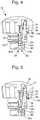
figure 4 représente une vue en demi-coupe d'une tête couronne de réglage dans une position vissée selon une autre forme de réalisation avec soupape de sécurité dans une configuration fermée ; et - la
figure 5 représente une vue similaire à lafigure 4 avec la tête couronne de réglage dans une position dévissée et la soupape de sécurité dans une configuration ouverte.
- the
figure 1 is a half-sectional view of an adjusting crown head in a screwed position with a safety valve in a closed configuration according to a first embodiment; - the
figure 2 represents a view similar to thefigure 1 with the adjusting ring head in an unscrewed position and the safety valve in an open configuration; - the
Figures 3a, 3b and 3c are each identical to thefigure 2 and in which schematically shows the progression of a fluid, for example helium, in the evacuation channel; - the
figure 4 is a half-sectional view of an adjusting crown head in a screwed position according to another embodiment with a safety valve in a closed configuration; and - the
figure 5 represents a view similar to thefigure 4 with the adjusting ring head in an unscrewed position and the safety valve in an open configuration.
Une tête couronne de réglage 10 notamment pour montre de plongée selon une première forme de réalisation de l'invention va maintenant être décrite en référence aux
La tête couronne 10 comporte un tube 20 destiné à être fixé sur un boitier de montre (non représentée) par vissage ou chassage dans la carrure du boitier. Le tube 20 comporte une partie taraudée 21 a disposée sur sa paroi interne 21 ainsi qu'un renflement 22a disposé le long de la circonférence de sa paroi externe 22. La tête couronne 10 comporte également un capot 11, lequel comprend un couvercle 12 et une jupe axiale 13 présentant une symétrie de révolution autour de l'axe de rotation A du capot 11. Le couvercle 12 et la jupe axiale 13 du capot 11 définissent une cavité 15 dans le capot 11. La tête couronne 10 comporte en outre un canon central 23 agencé dans la cavité 15 du capot 11 et solidaire à celui-ci. Le canon central 23 comporte sur sa paroi externe 25 une partie filetée 25a vissée dans la partie taraudée 21 a du tube 20.The
La tête couronne de réglage 10 comporte par ailleurs un joint d'étanchéité 17 interposé entre la jupe axiale 13 du capot 11 et le tube 20 de manière à garantir l'étanchéité de la tête couronne indépendamment du fait que le capot 11 se trouve dans une première position axiale dans laquelle la tête couronne est vissée ou dans une seconde position axiale dans laquelle la tête couronne est dévissée. Dans cette forme de réalisation, ce joint d'étanchéité 17 est un joint torique. Ce joint 17 est agencé entre en épaulement circulaire 14 réalisé dans la jupe axiale 13 et une bague de maintien 18 de forme annulaire. Cette bague 18 est fixée, par exemple par chassage, dans une rainure 16 de forme correspondante se trouvant vers la base de la jupe axiale 13 en regard du tube 20.The adjusting
En référence à la
La tête couronne de réglage 10 comporte également un piston 32 logé dans une ouverture centrale du canon central 23 ainsi qu'un organe élastique, par exemple un ressort de compression 34 du type hélicoïdal, dans une cavité définie par l'ensemble capot-canon d'une part et par le piston 32 d'autre part. Le ressort 34 est compressé axialement entre le couvercle 12 du capot 11 et un épaulement 32a du piston 32 et il permet notamment d'éloigner le capot 11 de l'épaulement du piston 32. Le piston 32 relie cinématiquement le capot 11 à une tige de commande (non représentée) du mouvement horloger logé dans la boite de montre. Cette tige de commande permet au porteur d'effectuer différentes commandes en fonction de la position axiale du capot 11 par rapport au tube 20, par exemple le remontage de la montre lorsque le capot 11 se trouve dans une première position axiale tel qu'illustré par la
Le piston 32 et le ressort 34 sont également impliqués dans la régulation de la pression à l'intérieur du boitier de montre grâce à une soupape de sécurité dont une description détaillée est donnée ci-dessous.The
Le piston et le ressort forment donc un ensemble qui a l'avantage d'être impliqué dans la réalisation de deux fonctions principales qui sont indépendantes l'une de l'autre, à savoir : l'activation de la tige de commande pour effectuer différents réglages d'une part, et la régulation de la pression à l'intérieur du boitier de montre d'autre part.The piston and the spring thus form an assembly which has the advantage of being involved in the realization of two main functions which are independent of one another, namely: the activation of the control rod to perform different adjustments on the one hand, and the regulation of the pressure inside the watch case on the other hand.
En outre, la tête couronne 10 comporte des moyens de blocage empêchant la désolidarisation entre le capot 11 et le tube 20.In addition, the
Conformément à l'invention, les moyens de blocage comprennent un épaulement 21 b agencé sur la paroi interne 21 du tube 20 et comportant une surface d'appui contre laquelle une partie du piston 32 peut venir en butée. Les moyens de blocage comprennent également un rebord 23a prévu à la base du canon central 23 et agencé pour venir en butée contre l'épaulement 32a prévu sur le piston 32.According to the invention, the locking means comprise a
Avantageusement, la partie du piston 32 pouvant venir en butée contre l'épaulement 21 b du tube 20 est formée par la tête 33a d'une vis de guidage 33 solidaire du piston 32. Plus particulièrement, le piston 32 comprend un taraudage dans lequel la vis de guidage 33 est vissée. La vis de guidage 33 comporte également une partie centrale évidée 33b en forme de cône ainsi qu'une partie annulaire périphérique 33c qui s'étend jusqu'à la paroi interne 21 du tube 20. La partie annulaire périphérique 33c de la tête 33a de la vis de guidage 33 est agencée pour venir en butée contre cet épaulement 21 b du tube 20 lorsque le capot 11 est amené dans sa seconde position axiale. En outre, le rebord 23a à la base du canon central 23 est agencé pour s'engager dans une encoche 32c prévue à cet effet sous la face inférieure de l'épaulement 32a du piston 32 lorsque ledit rebord 23a vient en butée contre la face inférieure de l'épaulement 32a du piston 32. Ainsi, lorsque la tête couronne 10 est dévissée, le canon central 23 sera bloqué par l'épaulement 32a du piston 32, qui lui-même sera bloqué, étant solidaire de la vis de guidage 33 elle-même bloquée par l'épaulement 21 b du tube 20. Ceci permet d'éviter un dévissement excessif de la tête couronne 10 de façon à empêcher que le capot 11 se désolidarise du tube 20.Advantageously, the portion of the
Afin de moins solliciter les joints d'étanchéité de la tête couronne, et de mieux réguler les variations de pression à l'intérieur du boitier de montre occasionnées par exemple par la remontée du plongeur à la surface, une soupape de sécurité est intégrée à la tête couronne.In order to less stress the seals of the crown head, and better regulate the pressure variations inside the watch case caused for example by the rise of the plunger to the surface, a safety valve is integrated in the crown head.
La soupape de sécurité comporte un canal d'évacuation agencé pour pouvoir être en communication fluidique avec l'intérieur du boitier de montre lorsque la soupape est dans une configuration ouverte afin d'évacuer un excès de pression dans le boitier.The safety valve has an evacuation channel arranged to be in fluid communication with the interior of the watch case when the valve is in an open configuration to remove excess pressure in the case.
Selon une variante, la soupape comporte un régulateur de pression agencé à l'intérieur du canal d'évacuation pour maitriser la vitesse de sortie d'un fluide qui se présente sous la forme d'un gaz, de préférence de l'hélium. Le régulateur de pression comporte à cet effet une bille 35 coopérant avec un siège de bille 37 monté à l'entrée 30 du canal d'évacuation.According to a variant, the valve comprises a pressure regulator arranged inside the evacuation channel to control the output velocity of a fluid which is in the form of a gas, preferably helium. The pressure regulator comprises for this purpose a
Le siège de bille 37, le tube 20 et la jupe axiale 13 présentent une symétrie de révolution par rapport à l'axe de rotation A du capot 11. La bille et son siège peuvent par exemple être à base de métal, de céramique ou de matériaux thermoplastiques entre autre.The
Le siège 37 comporte une base annulaire 37a comportant une ouverture dont l'axe de révolution coïncide avec l'axe de rotation A du capot 11. Le diamètre de cette ouverture est inférieur au diamètre de la bille 35. Cette ouverture correspond à l'entrée 30 du canal d'évacuation de la soupape. Le siège 37 comporte également une surface d'appui 37b inclinée et circulaire destinée à être en contact avec la bille 35, une paroi cylindrique 37d afin d'assurer le centrage de la bille 35 par rapport à l'axe de rotation A du capot 11 et une surface d'appui périphérique 37c disposée en regard de la partie annulaire périphérique 33c de la tête 33a de la vis de guidage 33.The
La tête 33a de la vis de guidage 33 est disposée en regard de la bille 35. La configuration et le positionnement de la vis de guidage 33 et du siège 37 permettent de former une cage délimitant un espace dans lequel la bille 35 peut se déplacer sous l'effet de la pression.The
La bille 35 est agencée sur son siège 37 de manière à obstruer le passage du gaz dans le canal d'évacuation lorsque la pression dans le boitier de montre, en amont de la bille, est inférieure une valeur prédéterminée. Cette valeur peut être adaptée aux circonstances, cette adaptation étant réalisée par le choix du ressort de compression 34 qui maintient une extrémité du piston 32 en appui contre la bille 35. Les propriétés du ressort 34 sont donc choisies pour gérer la contrainte qu'exerce le piston 32 sur la bille 35 afin de contrôler la pression d'ouverture de la soupape. On notera que la bille est toujours sous la contrainte du ressort 34 lorsque la tête couronne 10 est dans une configuration vissée (
En référence aux
Une tête couronne de réglage 10 pour montre de plongée selon une deuxième forme de réalisation va maintenant être décrite en référence aux
Selon les
Lorsque la tête couronne 10 est dans une configuration dévissée alors que la pression à l'intérieur du boitier de montre excède un seuil critique, le gaz vient en contact avec la membrane 40 qui est perméable aux gaz ce qui permet au gaz de la traverser, et de se déplacer le long du canal d'évacuation formé par les différents éléments dans la tête couronne jusqu'à la sortie 31 du canal afin de permettre l'évacuation du gaz hors de la soupape.When the
Un dévissement excessif de la tête couronne 10 de façon à empêcher que le capot 11 se désolidarise du tube 20 est évité grâce aux moyens de blocage similaires à ceux de la première variante.Excessive unhinging of the
Naturellement, l'invention n'est pas limitée aux modes de réalisation décrits en référence aux figures et des variantes pourraient être envisagées sans sortir du cadre de l'invention. Par exemple, le piston peut être d'un seul tenant ou être constitué de plusieurs pièces assemblées.Naturally, the invention is not limited to the embodiments described with reference to the figures and variants could be envisaged without departing from the scope of the invention. For example, the piston may be in one piece or consist of several parts assembled.
Claims (8)
Priority Applications (5)
| Application Number | Priority Date | Filing Date | Title |
|---|---|---|---|
| EP17182439.4A EP3432086B1 (en) | 2017-07-20 | 2017-07-20 | Safety valve for a timepiece |
| US16/035,928 US10871748B2 (en) | 2017-07-20 | 2018-07-16 | Safety valve for a timepiece |
| JP2018133940A JP6666962B2 (en) | 2017-07-20 | 2018-07-17 | Watch safety valve |
| KR1020180083709A KR102059748B1 (en) | 2017-07-20 | 2018-07-18 | Safety valve for a timepiece |
| CN201810794891.0A CN109283827B (en) | 2017-07-20 | 2018-07-19 | Safety valve for a timepiece |
Applications Claiming Priority (1)
| Application Number | Priority Date | Filing Date | Title |
|---|---|---|---|
| EP17182439.4A EP3432086B1 (en) | 2017-07-20 | 2017-07-20 | Safety valve for a timepiece |
Publications (2)
| Publication Number | Publication Date |
|---|---|
| EP3432086A1 true EP3432086A1 (en) | 2019-01-23 |
| EP3432086B1 EP3432086B1 (en) | 2020-04-15 |
Family
ID=59383514
Family Applications (1)
| Application Number | Title | Priority Date | Filing Date |
|---|---|---|---|
| EP17182439.4A Active EP3432086B1 (en) | 2017-07-20 | 2017-07-20 | Safety valve for a timepiece |
Country Status (5)
| Country | Link |
|---|---|
| US (1) | US10871748B2 (en) |
| EP (1) | EP3432086B1 (en) |
| JP (1) | JP6666962B2 (en) |
| KR (1) | KR102059748B1 (en) |
| CN (1) | CN109283827B (en) |
Cited By (1)
| Publication number | Priority date | Publication date | Assignee | Title |
|---|---|---|---|---|
| CN114545755A (en) * | 2020-11-25 | 2022-05-27 | 梅科股份公司 | Crown button for a timepiece |
Families Citing this family (5)
| Publication number | Priority date | Publication date | Assignee | Title |
|---|---|---|---|---|
| EP3432085B1 (en) * | 2017-07-20 | 2020-04-15 | Meco S.A. | Safety valve for a timepiece |
| EP3742235B1 (en) * | 2019-05-23 | 2022-01-26 | Meco S.A. | Push button system, and timepiece comprising same |
| EP3805869A1 (en) * | 2019-10-09 | 2021-04-14 | Meco S.A. | Threaded crown |
| CN112213940B (en) * | 2020-09-30 | 2021-09-28 | 西安易朴通讯技术有限公司 | Wearable device |
| KR20230099616A (en) | 2021-12-27 | 2023-07-04 | 이태웅 | Ceramic wrist watch with waterproof and vibrationproof packing |
Citations (3)
| Publication number | Priority date | Publication date | Assignee | Title |
|---|---|---|---|---|
| JPS5491150U (en) * | 1977-12-08 | 1979-06-27 | ||
| EP0556155A1 (en) * | 1992-02-12 | 1993-08-18 | Montres Rolex Sa | Water-tight control device for a watch |
| CH703455A1 (en) * | 2010-07-17 | 2012-01-31 | Pibor Iso S A | Crown i.e. winding crown, for use on watch case, has coupling units securing wheel and piston when head occupies stable translation position to modify function of timepiece movement and slide wheel inside tube |
Family Cites Families (18)
| Publication number | Priority date | Publication date | Assignee | Title |
|---|---|---|---|---|
| CH624259B (en) * | 1979-03-29 | Boninchi Sa | WATERPROOF PUSH-BUTTON FOR DIVING WATCH. | |
| CH682199B5 (en) * | 1992-02-07 | 1994-02-15 | Smh Management Services Ag | Safety valve for a timepiece diver. |
| CH691935A5 (en) * | 1997-06-11 | 2001-11-30 | Meco Sa Grenchen | Safety valve for a watch. |
| CH691936A5 (en) * | 1997-06-11 | 2001-11-30 | Meco Sa Grenchen | Actuating means with seal for a watch. |
| JP2003240877A (en) * | 2002-02-14 | 2003-08-27 | Citizen Watch Co Ltd | Exhaust valve |
| DE602004021083D1 (en) * | 2004-02-10 | 2009-06-25 | Tissot Sa | Device for Kroneschütz for a clock |
| JP4619815B2 (en) * | 2005-02-21 | 2011-01-26 | セイコーインスツル株式会社 | Portable watch and crown used for this watch |
| JP5279661B2 (en) * | 2009-08-28 | 2013-09-04 | セイコーインスツル株式会社 | Cell phone clock |
| JP5405945B2 (en) * | 2009-08-28 | 2014-02-05 | セイコーインスツル株式会社 | Cell phone clock |
| EP2607972B1 (en) * | 2011-12-22 | 2016-04-27 | The Swatch Group Research and Development Ltd. | Watertight push button for watch |
| EP2685327B1 (en) * | 2012-07-09 | 2018-09-05 | Omega SA | Push button for timepiece including a valve |
| CH707525B1 (en) * | 2013-01-24 | 2017-06-30 | Prétat Roland | Adjustment mechanism for watch. |
| JP6132162B2 (en) * | 2014-03-24 | 2017-05-24 | カシオ計算機株式会社 | Timing device and watch |
| JP2015230270A (en) * | 2014-06-06 | 2015-12-21 | カシオ計算機株式会社 | Push button structure and watch |
| EP3287855B1 (en) * | 2016-08-26 | 2019-05-01 | Meco S.A. | Adjustment crown for a timepiece |
| EP3432085B1 (en) * | 2017-07-20 | 2020-04-15 | Meco S.A. | Safety valve for a timepiece |
| EP3483670B1 (en) * | 2017-11-08 | 2020-07-29 | Omega SA | Safety valve for a watch |
| EP3483669B1 (en) * | 2017-11-08 | 2020-12-30 | Omega SA | Safety valve for a watch |
-
2017
- 2017-07-20 EP EP17182439.4A patent/EP3432086B1/en active Active
-
2018
- 2018-07-16 US US16/035,928 patent/US10871748B2/en active Active
- 2018-07-17 JP JP2018133940A patent/JP6666962B2/en active Active
- 2018-07-18 KR KR1020180083709A patent/KR102059748B1/en active IP Right Grant
- 2018-07-19 CN CN201810794891.0A patent/CN109283827B/en active Active
Patent Citations (3)
| Publication number | Priority date | Publication date | Assignee | Title |
|---|---|---|---|---|
| JPS5491150U (en) * | 1977-12-08 | 1979-06-27 | ||
| EP0556155A1 (en) * | 1992-02-12 | 1993-08-18 | Montres Rolex Sa | Water-tight control device for a watch |
| CH703455A1 (en) * | 2010-07-17 | 2012-01-31 | Pibor Iso S A | Crown i.e. winding crown, for use on watch case, has coupling units securing wheel and piston when head occupies stable translation position to modify function of timepiece movement and slide wheel inside tube |
Cited By (1)
| Publication number | Priority date | Publication date | Assignee | Title |
|---|---|---|---|---|
| CN114545755A (en) * | 2020-11-25 | 2022-05-27 | 梅科股份公司 | Crown button for a timepiece |
Also Published As
| Publication number | Publication date |
|---|---|
| CN109283827B (en) | 2020-11-27 |
| KR102059748B1 (en) | 2019-12-26 |
| US20190025764A1 (en) | 2019-01-24 |
| US10871748B2 (en) | 2020-12-22 |
| JP2019020414A (en) | 2019-02-07 |
| KR20190010464A (en) | 2019-01-30 |
| JP6666962B2 (en) | 2020-03-18 |
| EP3432086B1 (en) | 2020-04-15 |
| CN109283827A (en) | 2019-01-29 |
Similar Documents
| Publication | Publication Date | Title |
|---|---|---|
| EP3432086B1 (en) | Safety valve for a timepiece | |
| CH714005A2 (en) | Crown head comprising a safety valve for a timepiece. | |
| EP3432085B1 (en) | Safety valve for a timepiece | |
| EP3483669B1 (en) | Safety valve for a watch | |
| EP3287855B1 (en) | Adjustment crown for a timepiece | |
| EP3483670B1 (en) | Safety valve for a watch | |
| EP2746870A1 (en) | Dismountable crown | |
| EP2107432A1 (en) | Pushbutton control device for a watch | |
| FR2615583A1 (en) | ADJUSTABLE PRESSURE VALVE FOR UNDERWATER INFLATABLE ELEMENTS WITH ABSOLUTE IMPERMEABILITY AND RATIONALLY DESIGNED FOR REDUCED PRODUCTION COSTS | |
| EP3432084B1 (en) | Safety valve for a watch | |
| EP3428740B1 (en) | Safety valve for a watch | |
| EP1975749B1 (en) | Timepiece with elastically-held movement | |
| EP3428741B1 (en) | Safety valve for a watch | |
| CH714006A2 (en) | Safety valve, crown head and timepiece. | |
| EP0611219A1 (en) | Diaphragm safety cartridge valve of modular conception | |
| EP1205826A1 (en) | Actuating device for timepiece of screwed-on crown type | |
| CH331280A (en) | Waterproof crown for measuring device, especially for watch | |
| CH714310A2 (en) | Security valve for watch. | |
| CH346176A (en) | Waterproof winding crown | |
| CH714007A2 (en) | Security valve for watch. | |
| CH720145A2 (en) | Setting crown for timepiece. | |
| EP4206827A1 (en) | Safety valve for a watch | |
| CH714309A2 (en) | Security valve for watch. | |
| CH719331A2 (en) | Safety valve for watch. | |
| CH718165B1 (en) | Control assembly for a clockwork movement of a timepiece. |
Legal Events
| Date | Code | Title | Description |
|---|---|---|---|
| PUAI | Public reference made under article 153(3) epc to a published international application that has entered the european phase |
Free format text: ORIGINAL CODE: 0009012 |
|
| STAA | Information on the status of an ep patent application or granted ep patent |
Free format text: STATUS: THE APPLICATION HAS BEEN PUBLISHED |
|
| AK | Designated contracting states |
Kind code of ref document: A1 Designated state(s): AL AT BE BG CH CY CZ DE DK EE ES FI FR GB GR HR HU IE IS IT LI LT LU LV MC MK MT NL NO PL PT RO RS SE SI SK SM TR |
|
| AX | Request for extension of the european patent |
Extension state: BA ME |
|
| STAA | Information on the status of an ep patent application or granted ep patent |
Free format text: STATUS: REQUEST FOR EXAMINATION WAS MADE |
|
| RBV | Designated contracting states (corrected) |
Designated state(s): AL AT BE BG CH CY CZ DE DK EE ES FI FR GB GR HR HU IE IS IT LI LT LU LV MC MK MT NL NO PL PT RO RS SE SI SK SM TR |
|
| 17P | Request for examination filed |
Effective date: 20190726 |
|
| GRAP | Despatch of communication of intention to grant a patent |
Free format text: ORIGINAL CODE: EPIDOSNIGR1 |
|
| STAA | Information on the status of an ep patent application or granted ep patent |
Free format text: STATUS: GRANT OF PATENT IS INTENDED |
|
| INTG | Intention to grant announced |
Effective date: 20191213 |
|
| GRAS | Grant fee paid |
Free format text: ORIGINAL CODE: EPIDOSNIGR3 |
|
| GRAA | (expected) grant |
Free format text: ORIGINAL CODE: 0009210 |
|
| STAA | Information on the status of an ep patent application or granted ep patent |
Free format text: STATUS: THE PATENT HAS BEEN GRANTED |
|
| AK | Designated contracting states |
Kind code of ref document: B1 Designated state(s): AL AT BE BG CH CY CZ DE DK EE ES FI FR GB GR HR HU IE IS IT LI LT LU LV MC MK MT NL NO PL PT RO RS SE SI SK SM TR |
|
| REG | Reference to a national code |
Ref country code: CH Ref legal event code: EP |
|
| REG | Reference to a national code |
Ref country code: CH Ref legal event code: NV Representative=s name: ICB INGENIEURS CONSEILS EN BREVETS SA, CH |
|
| REG | Reference to a national code |
Ref country code: DE Ref legal event code: R096 Ref document number: 602017014666 Country of ref document: DE |
|
| REG | Reference to a national code |
Ref country code: IE Ref legal event code: FG4D Free format text: LANGUAGE OF EP DOCUMENT: FRENCH |
|
| REG | Reference to a national code |
Ref country code: AT Ref legal event code: REF Ref document number: 1258038 Country of ref document: AT Kind code of ref document: T Effective date: 20200515 |
|
| REG | Reference to a national code |
Ref country code: NL Ref legal event code: MP Effective date: 20200415 |
|
| REG | Reference to a national code |
Ref country code: LT Ref legal event code: MG4D |
|
| PG25 | Lapsed in a contracting state [announced via postgrant information from national office to epo] |
Ref country code: IS Free format text: LAPSE BECAUSE OF FAILURE TO SUBMIT A TRANSLATION OF THE DESCRIPTION OR TO PAY THE FEE WITHIN THE PRESCRIBED TIME-LIMIT Effective date: 20200815 Ref country code: GR Free format text: LAPSE BECAUSE OF FAILURE TO SUBMIT A TRANSLATION OF THE DESCRIPTION OR TO PAY THE FEE WITHIN THE PRESCRIBED TIME-LIMIT Effective date: 20200716 Ref country code: NO Free format text: LAPSE BECAUSE OF FAILURE TO SUBMIT A TRANSLATION OF THE DESCRIPTION OR TO PAY THE FEE WITHIN THE PRESCRIBED TIME-LIMIT Effective date: 20200715 Ref country code: FI Free format text: LAPSE BECAUSE OF FAILURE TO SUBMIT A TRANSLATION OF THE DESCRIPTION OR TO PAY THE FEE WITHIN THE PRESCRIBED TIME-LIMIT Effective date: 20200415 Ref country code: NL Free format text: LAPSE BECAUSE OF FAILURE TO SUBMIT A TRANSLATION OF THE DESCRIPTION OR TO PAY THE FEE WITHIN THE PRESCRIBED TIME-LIMIT Effective date: 20200415 Ref country code: SE Free format text: LAPSE BECAUSE OF FAILURE TO SUBMIT A TRANSLATION OF THE DESCRIPTION OR TO PAY THE FEE WITHIN THE PRESCRIBED TIME-LIMIT Effective date: 20200415 Ref country code: PT Free format text: LAPSE BECAUSE OF FAILURE TO SUBMIT A TRANSLATION OF THE DESCRIPTION OR TO PAY THE FEE WITHIN THE PRESCRIBED TIME-LIMIT Effective date: 20200817 Ref country code: LT Free format text: LAPSE BECAUSE OF FAILURE TO SUBMIT A TRANSLATION OF THE DESCRIPTION OR TO PAY THE FEE WITHIN THE PRESCRIBED TIME-LIMIT Effective date: 20200415 |
|
| REG | Reference to a national code |
Ref country code: AT Ref legal event code: MK05 Ref document number: 1258038 Country of ref document: AT Kind code of ref document: T Effective date: 20200415 |
|
| PG25 | Lapsed in a contracting state [announced via postgrant information from national office to epo] |
Ref country code: BG Free format text: LAPSE BECAUSE OF FAILURE TO SUBMIT A TRANSLATION OF THE DESCRIPTION OR TO PAY THE FEE WITHIN THE PRESCRIBED TIME-LIMIT Effective date: 20200715 Ref country code: RS Free format text: LAPSE BECAUSE OF FAILURE TO SUBMIT A TRANSLATION OF THE DESCRIPTION OR TO PAY THE FEE WITHIN THE PRESCRIBED TIME-LIMIT Effective date: 20200415 Ref country code: LV Free format text: LAPSE BECAUSE OF FAILURE TO SUBMIT A TRANSLATION OF THE DESCRIPTION OR TO PAY THE FEE WITHIN THE PRESCRIBED TIME-LIMIT Effective date: 20200415 Ref country code: HR Free format text: LAPSE BECAUSE OF FAILURE TO SUBMIT A TRANSLATION OF THE DESCRIPTION OR TO PAY THE FEE WITHIN THE PRESCRIBED TIME-LIMIT Effective date: 20200415 |
|
| PG25 | Lapsed in a contracting state [announced via postgrant information from national office to epo] |
Ref country code: AL Free format text: LAPSE BECAUSE OF FAILURE TO SUBMIT A TRANSLATION OF THE DESCRIPTION OR TO PAY THE FEE WITHIN THE PRESCRIBED TIME-LIMIT Effective date: 20200415 |
|
| REG | Reference to a national code |
Ref country code: DE Ref legal event code: R097 Ref document number: 602017014666 Country of ref document: DE |
|
| PG25 | Lapsed in a contracting state [announced via postgrant information from national office to epo] |
Ref country code: AT Free format text: LAPSE BECAUSE OF FAILURE TO SUBMIT A TRANSLATION OF THE DESCRIPTION OR TO PAY THE FEE WITHIN THE PRESCRIBED TIME-LIMIT Effective date: 20200415 Ref country code: DK Free format text: LAPSE BECAUSE OF FAILURE TO SUBMIT A TRANSLATION OF THE DESCRIPTION OR TO PAY THE FEE WITHIN THE PRESCRIBED TIME-LIMIT Effective date: 20200415 Ref country code: EE Free format text: LAPSE BECAUSE OF FAILURE TO SUBMIT A TRANSLATION OF THE DESCRIPTION OR TO PAY THE FEE WITHIN THE PRESCRIBED TIME-LIMIT Effective date: 20200415 Ref country code: SM Free format text: LAPSE BECAUSE OF FAILURE TO SUBMIT A TRANSLATION OF THE DESCRIPTION OR TO PAY THE FEE WITHIN THE PRESCRIBED TIME-LIMIT Effective date: 20200415 Ref country code: CZ Free format text: LAPSE BECAUSE OF FAILURE TO SUBMIT A TRANSLATION OF THE DESCRIPTION OR TO PAY THE FEE WITHIN THE PRESCRIBED TIME-LIMIT Effective date: 20200415 Ref country code: IT Free format text: LAPSE BECAUSE OF FAILURE TO SUBMIT A TRANSLATION OF THE DESCRIPTION OR TO PAY THE FEE WITHIN THE PRESCRIBED TIME-LIMIT Effective date: 20200415 Ref country code: RO Free format text: LAPSE BECAUSE OF FAILURE TO SUBMIT A TRANSLATION OF THE DESCRIPTION OR TO PAY THE FEE WITHIN THE PRESCRIBED TIME-LIMIT Effective date: 20200415 Ref country code: ES Free format text: LAPSE BECAUSE OF FAILURE TO SUBMIT A TRANSLATION OF THE DESCRIPTION OR TO PAY THE FEE WITHIN THE PRESCRIBED TIME-LIMIT Effective date: 20200415 |
|
| REG | Reference to a national code |
Ref country code: DE Ref legal event code: R119 Ref document number: 602017014666 Country of ref document: DE |
|
| PLBE | No opposition filed within time limit |
Free format text: ORIGINAL CODE: 0009261 |
|
| STAA | Information on the status of an ep patent application or granted ep patent |
Free format text: STATUS: NO OPPOSITION FILED WITHIN TIME LIMIT |
|
| PG25 | Lapsed in a contracting state [announced via postgrant information from national office to epo] |
Ref country code: MC Free format text: LAPSE BECAUSE OF FAILURE TO SUBMIT A TRANSLATION OF THE DESCRIPTION OR TO PAY THE FEE WITHIN THE PRESCRIBED TIME-LIMIT Effective date: 20200415 Ref country code: PL Free format text: LAPSE BECAUSE OF FAILURE TO SUBMIT A TRANSLATION OF THE DESCRIPTION OR TO PAY THE FEE WITHIN THE PRESCRIBED TIME-LIMIT Effective date: 20200415 Ref country code: SK Free format text: LAPSE BECAUSE OF FAILURE TO SUBMIT A TRANSLATION OF THE DESCRIPTION OR TO PAY THE FEE WITHIN THE PRESCRIBED TIME-LIMIT Effective date: 20200415 |
|
| 26N | No opposition filed |
Effective date: 20210118 |
|
| REG | Reference to a national code |
Ref country code: BE Ref legal event code: MM Effective date: 20200731 |
|
| PG25 | Lapsed in a contracting state [announced via postgrant information from national office to epo] |
Ref country code: LU Free format text: LAPSE BECAUSE OF NON-PAYMENT OF DUE FEES Effective date: 20200720 |
|
| PG25 | Lapsed in a contracting state [announced via postgrant information from national office to epo] |
Ref country code: BE Free format text: LAPSE BECAUSE OF NON-PAYMENT OF DUE FEES Effective date: 20200731 Ref country code: DE Free format text: LAPSE BECAUSE OF NON-PAYMENT OF DUE FEES Effective date: 20210202 Ref country code: SI Free format text: LAPSE BECAUSE OF FAILURE TO SUBMIT A TRANSLATION OF THE DESCRIPTION OR TO PAY THE FEE WITHIN THE PRESCRIBED TIME-LIMIT Effective date: 20200415 |
|
| PG25 | Lapsed in a contracting state [announced via postgrant information from national office to epo] |
Ref country code: IE Free format text: LAPSE BECAUSE OF NON-PAYMENT OF DUE FEES Effective date: 20200720 |
|
| GBPC | Gb: european patent ceased through non-payment of renewal fee |
Effective date: 20210720 |
|
| PG25 | Lapsed in a contracting state [announced via postgrant information from national office to epo] |
Ref country code: GB Free format text: LAPSE BECAUSE OF NON-PAYMENT OF DUE FEES Effective date: 20210720 |
|
| PG25 | Lapsed in a contracting state [announced via postgrant information from national office to epo] |
Ref country code: TR Free format text: LAPSE BECAUSE OF FAILURE TO SUBMIT A TRANSLATION OF THE DESCRIPTION OR TO PAY THE FEE WITHIN THE PRESCRIBED TIME-LIMIT Effective date: 20200415 Ref country code: MT Free format text: LAPSE BECAUSE OF FAILURE TO SUBMIT A TRANSLATION OF THE DESCRIPTION OR TO PAY THE FEE WITHIN THE PRESCRIBED TIME-LIMIT Effective date: 20200415 Ref country code: CY Free format text: LAPSE BECAUSE OF FAILURE TO SUBMIT A TRANSLATION OF THE DESCRIPTION OR TO PAY THE FEE WITHIN THE PRESCRIBED TIME-LIMIT Effective date: 20200415 |
|
| PG25 | Lapsed in a contracting state [announced via postgrant information from national office to epo] |
Ref country code: MK Free format text: LAPSE BECAUSE OF FAILURE TO SUBMIT A TRANSLATION OF THE DESCRIPTION OR TO PAY THE FEE WITHIN THE PRESCRIBED TIME-LIMIT Effective date: 20200415 |
|
| PGFP | Annual fee paid to national office [announced via postgrant information from national office to epo] |
Ref country code: FR Payment date: 20230621 Year of fee payment: 7 |
|
| P01 | Opt-out of the competence of the unified patent court (upc) registered |
Effective date: 20230719 |
|
| PGFP | Annual fee paid to national office [announced via postgrant information from national office to epo] |
Ref country code: CH Payment date: 20230801 Year of fee payment: 7 |