EP3428094B1 - Multimodal transport interworking system - Google Patents
Multimodal transport interworking system Download PDFInfo
- Publication number
- EP3428094B1 EP3428094B1 EP17865533.8A EP17865533A EP3428094B1 EP 3428094 B1 EP3428094 B1 EP 3428094B1 EP 17865533 A EP17865533 A EP 17865533A EP 3428094 B1 EP3428094 B1 EP 3428094B1
- Authority
- EP
- European Patent Office
- Prior art keywords
- loading device
- goods loading
- cargo vehicle
- rail
- telescopic rod
- Prior art date
- Legal status (The legal status is an assumption and is not a legal conclusion. Google has not performed a legal analysis and makes no representation as to the accuracy of the status listed.)
- Active
Links
- 230000007246 mechanism Effects 0.000 claims description 73
- 238000012546 transfer Methods 0.000 claims description 49
- 239000000725 suspension Substances 0.000 claims description 31
- 230000032258 transport Effects 0.000 description 18
- 238000011161 development Methods 0.000 description 9
- 230000000694 effects Effects 0.000 description 7
- 238000000034 method Methods 0.000 description 6
- 229910000831 Steel Inorganic materials 0.000 description 5
- 239000010959 steel Substances 0.000 description 5
- 238000010521 absorption reaction Methods 0.000 description 4
- 239000003990 capacitor Substances 0.000 description 4
- 238000002955 isolation Methods 0.000 description 4
- 238000003466 welding Methods 0.000 description 3
- 230000004075 alteration Effects 0.000 description 2
- 238000005452 bending Methods 0.000 description 2
- 238000006073 displacement reaction Methods 0.000 description 2
- 238000012986 modification Methods 0.000 description 2
- 230000004048 modification Effects 0.000 description 2
- 230000035939 shock Effects 0.000 description 2
- XLYOFNOQVPJJNP-UHFFFAOYSA-N water Substances O XLYOFNOQVPJJNP-UHFFFAOYSA-N 0.000 description 2
- 230000001133 acceleration Effects 0.000 description 1
- 230000003044 adaptive effect Effects 0.000 description 1
- 230000005540 biological transmission Effects 0.000 description 1
- 238000004891 communication Methods 0.000 description 1
- 238000010276 construction Methods 0.000 description 1
- 238000003912 environmental pollution Methods 0.000 description 1
- 230000006870 function Effects 0.000 description 1
- 230000007774 longterm Effects 0.000 description 1
- 230000008520 organization Effects 0.000 description 1
- 230000008569 process Effects 0.000 description 1
- 238000012876 topography Methods 0.000 description 1
- 238000013519 translation Methods 0.000 description 1
Images


Classifications
-
- G—PHYSICS
- G06—COMPUTING; CALCULATING OR COUNTING
- G06Q—INFORMATION AND COMMUNICATION TECHNOLOGY [ICT] SPECIALLY ADAPTED FOR ADMINISTRATIVE, COMMERCIAL, FINANCIAL, MANAGERIAL OR SUPERVISORY PURPOSES; SYSTEMS OR METHODS SPECIALLY ADAPTED FOR ADMINISTRATIVE, COMMERCIAL, FINANCIAL, MANAGERIAL OR SUPERVISORY PURPOSES, NOT OTHERWISE PROVIDED FOR
- G06Q10/00—Administration; Management
- G06Q10/08—Logistics, e.g. warehousing, loading or distribution; Inventory or stock management
- G06Q10/083—Shipping
- G06Q10/0835—Relationships between shipper or supplier and carriers
- G06Q10/08355—Routing methods
-
- B—PERFORMING OPERATIONS; TRANSPORTING
- B61—RAILWAYS
- B61B—RAILWAY SYSTEMS; EQUIPMENT THEREFOR NOT OTHERWISE PROVIDED FOR
- B61B3/00—Elevated railway systems with suspended vehicles
-
- B—PERFORMING OPERATIONS; TRANSPORTING
- B61—RAILWAYS
- B61B—RAILWAY SYSTEMS; EQUIPMENT THEREFOR NOT OTHERWISE PROVIDED FOR
- B61B13/00—Other railway systems
- B61B13/04—Monorail systems
- B61B13/06—Saddle or like balanced type
-
- B—PERFORMING OPERATIONS; TRANSPORTING
- B61—RAILWAYS
- B61D—BODY DETAILS OR KINDS OF RAILWAY VEHICLES
- B61D47/00—Loading or unloading devices combined with vehicles, e.g. loading platforms, doors convertible into loading and unloading ramps
-
- B—PERFORMING OPERATIONS; TRANSPORTING
- B65—CONVEYING; PACKING; STORING; HANDLING THIN OR FILAMENTARY MATERIAL
- B65G—TRANSPORT OR STORAGE DEVICES, e.g. CONVEYORS FOR LOADING OR TIPPING, SHOP CONVEYOR SYSTEMS OR PNEUMATIC TUBE CONVEYORS
- B65G63/00—Transferring or trans-shipping at storage areas, railway yards or harbours or in opening mining cuts; Marshalling yard installations
- B65G63/04—Transferring or trans-shipping at storage areas, railway yards or harbours or in opening mining cuts; Marshalling yard installations with essentially-horizontal transit by bridges equipped with conveyors
-
- B—PERFORMING OPERATIONS; TRANSPORTING
- B65—CONVEYING; PACKING; STORING; HANDLING THIN OR FILAMENTARY MATERIAL
- B65G—TRANSPORT OR STORAGE DEVICES, e.g. CONVEYORS FOR LOADING OR TIPPING, SHOP CONVEYOR SYSTEMS OR PNEUMATIC TUBE CONVEYORS
- B65G67/00—Loading or unloading vehicles
- B65G67/02—Loading or unloading land vehicles
Definitions
- the embodiments of the present invention relate to the technical field of logistics, and in particular to a multimodal transportation interworking system.
- Multimodal transportation as a high-efficiency mode of transportation, represents the development direction of the logistics industry.
- 2014-2020 China's Medium- and Long-Term Development Plan for Logistics Industry (2014-2020)
- 2014-2020 it has been stressed 18 times to greatly develop multimodal transportation, and multimodal transportation is placed at the strategic level in development of the logistics industry.
- Document DE 43 32 232 C1 discloses a device for the rapid handling of transport containers.
- Document US 2005/158158 A1 discloses a method and an apparatus for railroad transport.
- the present disclosure achieves technical effects of multimodal transportation between ports and railway, air logistics centers.
- the present invention provides a multimodal transportation interworking system, and the system at least comprises:
- the rail system is bilaterally symmetrically mounted with two rail beams, and the two rail beams are respectively provided with a plurality of cargo vehicles which are movable thereon, and the goods loading device is suspended on a lower end of the plurality of cargo vehicles below the rail beam at each side.
- the rail beams are of a box-type structure, and a lower surface of the rail beams is provided with an opening which extends through from a front end to a rear end thereof, and the cargo vehicle is supported at a lower surface of an inner cavity of the rail beams.
- each of the cargo vehicles comprises a cargo vehicle bogie being supported at the lower surface of the inner cavity of the rail beams.
- the cargo vehicle bogie comprises a bogie frame whose front and rear ends are connected with gearboxes respectively, and each of the gearboxes is symmetrically provided with two output shafts on left and right sides.
- a travelling wheel is mounted on each of the output shafts, and the cargo vehicle bogie runs on the rail beams by four travelling wheels.
- Front and rear ends of two gearboxes are connected to two frame intermediate connections respectively, and front and rear ends of the two frame intermediate connections are respectively connected to two traction electric motors which control the cargo vehicle bogie to run.
- a lower end of the cargo vehicle bogie is connected to a goods loading device integrated spreader via a suspension device after passing through the opening, and a lower end of the goods loading device integrated spreader is connected to the goods loading device.
- the processor is connected to the traction electric motor.
- a left side and a right side of a housing of each of the traction electric motors are symmetrically connected with two guide wheel mounting seats on a lower portion thereof, and guide wheels are mounted on the two guide wheel mounting seats respectively.
- Guide rails are provided on left and right side walls of the opening of the rail beams respectively, and the two guide wheels move along the two guide rails respectively.
- the suspension device comprises a center pin.
- An upper end of the center pin is connected to a lower end of the bogie frame, and a lower end of the center pin is connected with a connection seat which is connected to two suspension arms via multiple first spindles.
- Lower ends of the two suspension arms are connected to a mounting seat via multiple second spindles, and the mounting seat is connected to the goods loading device integrated spreader.
- the transfer apparatus at least comprises: a conveyance mechanism, a grab mechanism and a lift mechanism; the grab mechanism suitable for placing the goods loading device on the conveyance mechanism; the conveyance mechanism suitable for transporting the goods loading device to the lift mechanism; the lift mechanism suitable for lifting or lowering the goods loading device; the goods loading device suitable to be loaded onto or unloaded from the cargo vehicle; and the processor being communicatively connected to the conveyance mechanism, the grab mechanism and the lift mechanism.
- the conveyance mechanism at least comprises: a first frame, a chain, a first group of rotation shafts and a power outputting device; the first group of rotation shafts is disposed on the first frame; each rotation shaft of the first group of rotation shafts is provided with gears; the chain is fitted around the gears to drive each rotation shaft of the first group of rotation shafts to rotate; and a power output end of the power outputting device is connected to the chain.
- the grab mechanism at least comprises: a telescopic arm, a first support rod, a second support rod, a first telescopic rod, a second telescopic rod, a third telescopic rod and a spreader; a first end of the first support rod is fixedly connected to the first frame, and a second end of the first support rod is hinged to a first end of the second support rod; a second end of the second support rod is hinged to the telescopic arm; a first end of the first telescopic rod is fixedly connected to the first frame, and a second end of the first telescopic rod is hinged to the second support rod; a first end of the second telescopic rod is hinged to the first end of the second support rod, and a second end of the second telescopic rod is hinged to a first end of the telescopic arm; a first end of the third telescopic rod is fixedly connected to the first end of the telescopic arm, and a second end of
- the transfer apparatus comprises: an underframe, a lifting device, a lifting table, a lift driving device, a plurality of travel wheels and a travel driving device;
- One or more technical solutions in accordance with the present invention at least have the following technical effects or advantages: by a rail system connecting various ports with railway and air logistics centers, and a processor controlling a transfer apparatus to transfer a goods loading device and controlling a cargo vehicle to move on the rail system after the goods loading device is secured on the cargo vehicle, multimodal transportation between ports and railway, air logistics centers is achieved.
- a rail system connecting various ports with railway and air logistics centers, and a processor controlling a transfer apparatus to transfer a goods loading device and controlling a cargo vehicle to move on the rail system after the goods loading device is secured on the cargo vehicle, multimodal transportation between ports and railway, air logistics centers is achieved.
- road goods loading device transportation trucks with the rail system, not only the transport efficiency is increased, but also the pressure on the ground transportation is reduced and the environment is also protected.
- a multimodal transportation interworking system in accordance with embodiments of the present invention can achieve such technical effect as multimodal transportation between ports and railways, air logistics centers.
- a technical solution according to embodiments of the present invention follows a general idea as below: a rail system is provided to connect various ports with railways, air logistics centers, and a processor is provided to control a transfer apparatus to transfer a goods loading device and control a cargo vehicle to move on a rail beam after the goods loading device is secured onto the cargo vehicle.
- a rail system is provided to connect various ports with railways, air logistics centers, and a processor is provided to control a transfer apparatus to transfer a goods loading device and control a cargo vehicle to move on a rail beam after the goods loading device is secured onto the cargo vehicle.
- multimodal transportation between ports and railway, air logistics centers is achieved.
- road goods loading device transportation trucks with the rail system, not only the transport efficiency is increased, but also the pressure on the ground transportation is reduced and the environment is also protected.
- a multimodal transportation interworking system is provided according to embodiments of the present invention, at least comprising:
- the transfer apparatus 32 transfers the goods loading device 33 from a transportation tool to the cargo vehicle 31 and loads the same onto the cargo vehicle 31, and the processor controls the cargo vehicle 31 to move on the rail beams, or the transfer apparatus 32 unloads the goods loading device 33 from the cargo vehicle 31 and conveys the same onto the transportation tool.
- a structure according to a first embodiment of the present invention comprises a rail system 1 comprising a rail pillar 30 and two rail beams 2.
- a lower surface of an upper portion of the rail pillar 30 is bilaterally symmetrically provided with two C-shaped rail grooves 8, and the two rail grooves 8 run through from a front end to a rear end of the rail system 1.
- Two rail beams 2 are mounted within the two rail grooves 8.
- the rail system 1 may be conveniently and stably disposed in isolation strips.
- the rail beams 2 are of a thin-walled steel box-type structure, and a lower surface of the rail beams 2 is provided with an opening 9 extending through from a front end to rear end thereof.
- Inner cavities of the two rail beams 2 are provided with multiple cargo vehicles 31 that are movable within the rail beams 2.
- the inner cavity of each of the rail beams 2 is provided with two cargo vehicles 31 which are supported on a lower surface of the inner cavity of the rail beam 2.
- a lower end of the cargo vehicle 31 is connected with a goods loading device, which is the goods loading device 33 in this embodiment.
- the cargo vehicle 31 comprises a cargo vehicle bogie 3, a suspension device 10 connected under the cargo vehicle bogie 3, as well as a goods loading device integrated spreader 11 connected under the suspension device 10.
- a lower end of the goods loading device integrated spreader 11 is connected to the goods loading device 33.
- the present embodiment adopts a super-capacitor power supply mode.
- the cargo vehicle bogie 3 comprises a bogie frame 12 that is in a welded structure.
- a front end and a rear end of the bogie frame 12 are connected with two gearboxes 13 by welding, respectively, and each of the gearboxes 13 is symmetrically provided with two output shafts 14 on left and right sides thereof, and a travelling wheel 15 is mounted on each of the output shafts 14.
- the cargo vehicle bogie 3 runs on a lower surface of the inner cavity of the rail beam 2 by means of four travelling wheels 15.
- the front and rear ends of the two gearboxes 13 are connected to two frame intermediate connections 16 by bolts respectively, and the front and rear ends of the two frame intermediate connections 16 are connected by bolts with housings of two traction electric motors 17 that control the cargo vehicle bogie 3 to run.
- a left side and a right side of the housing of each of the traction electric motors 17 are symmetrically welded with two guide wheel mounting seats 18 on a lower portion thereof, and guide wheels 19 are mounted on the two guide wheel mounting seats 18 respectively.
- Guide rails 20 are provided on left and right side walls of the inner cavity of the rail beams 2 respectively, and the two guide wheels 19 move back and forth along the two guide rails 20, respectively.
- Each of the travelling wheels 15 and guide wheels 19 adopts rubber tires.
- a lower end of the bogie frame 12 is connected with the goods loading device integrated spreader 11 via the suspension device 10, and a lower end of the goods loading device integrated spreader 11 is connected to the goods loading device 33.
- the four cargo vehicle bogies 3 travel on the two rail beams 2, thereby driving the two goods loading devices 33 suspended under the four cargo vehicle bogies 3 to move along a direction of the rail beams 2.
- the transportation of the goods loading device 33 can be easily achieved through electric control.
- the four travelling wheels 15 of each cargo vehicle bogie 3 guarantees a steady travel on the rail beam 2, and the four guide wheels 19 of each cargo vehicle bogie 3 move back and forth along the guide rails 20 to effect the transportation of the goods loading device 33.
- the guide wheels 19 are provided to ensure that the cargo vehicle bogie 3 can steer steadily. All the travelling wheels 15 and the guide wheels 19 adopt rubber tires, so that an effect of shock absorption can be achieved when the cargo vehicle bogie 3 runs.
- the rail system 1 may be disposed in isolation strips, and multiple cargo vehicles 31 run on the two rail beams 2 in directions opposite to each other, respectively. Therefore, the air space is put into sufficient utilization, and no effect will be exerted on ground operations within the port, thus existing resources of docks can be utilized sufficiently for automation reformation, and problems such as dock congestion, lack of space and transport inefficiency can be solved. Thereby high-efficiency, low-cost and environment-friendly goods loading device quick and intelligent transport can be achieved, and meanwhile the transport system is simply structured, secure and reliable.
- the mounted rail beams 2 and the four cargo vehicle bogies 3 have a simple and compact structure without occupying extra space, and the structure of the rail beams 2 is also simple and makes it convenient for the cargo vehicle bogies 3 to move securely thereon.
- the rail beam 2 may further be in a C-shaped channel steel structure, which also falls within the protection scope of the present invention.
- a structure according to a second embodiment of the present invention comprises a rail system 1 comprising a rail pillar 30 and two rail beams 2.
- a lower surface of an upper portion of the rail pillar 30 is bilaterally symmetrically provided with two C-shaped rail grooves 8, and the two rail grooves 8 run through from a front end to a rear end of the rail system 1.
- Two rail beams 2 are mounted within the two rail grooves 8.
- the rail system 1 may be conveniently and stably disposed in isolation strips.
- the rail beams 2 are of a thin-walled steel box-type structure.
- a lower surface of the rail beams 2 is provided with an opening 9 extending through from a front end to a rear end thereof, and inner cavities of the two rail beams 2 are provided with multiple cargo vehicles 31 that are movable within the rail beams 2.
- the inner cavity of each of the rail beams 2 is provided with two cargo vehicles 31 which are supported at a lower surface of the inner cavity of the rail beams 2.
- the cargo vehicle 31 comprises a cargo vehicle bogie 3, a suspension device 10 connected under the cargo vehicle bogie 3, as well as a goods loading device integrated spreader 11 connected under the suspension device 10.
- a lower end of the goods loading device integrated spreader 11 is connected with the goods loading device 33.
- the present embodiment adopts a super-capacitor power supply mode.
- the cargo vehicle bogie 3 comprises a bogie frame 12 that is in a welded structure.
- a front end and a rear end of the bogie frame 12 are connected with two gearboxes 13 by welding respectively, and each of the gearboxes 13 is symmetrically provided with two output shafts 14 on left and right sides thereof, and a travelling wheel 15 is mounted on each of the output shafts 14.
- the cargo vehicle bogie 3 runs on the lower surface of the inner cavity of the rail beam 2 by means of four travelling wheels 15.
- Front and rear ends of the two gearboxes 13 are connected to two frame intermediate connections 16 by bolts respectively, and the front and rear ends of the two frame intermediate connections 16 are connected by bolts wtih housings of two traction electric motors 17 that control the cargo vehicle bogie 3 to run.
- a left side and a right side of the housing of each of the traction electric motors 17 are symmetrically welded with two guide wheel mounting seats 18 on a lower portion thereof, and guide wheels 19 are mounted on the two guide wheel mounting seats 18 respectively.
- Guide rails 20 are provided on left and right side walls of the inner cavity of the rail beams 2 respectively, and the two guide wheels 19 move back and forth along the two guide rails 20, respectively.
- Each of the travelling wheels 15 and guide wheels 19 adopts rubber tires.
- a lower end of the bogie frame 12 is connected to the goods loading device integrated spreader 11 via the suspension device 10 after passing through an opening 9, and a lower end of the goods loading device integrated spreader 11 is connected to the goods loading device 33.
- the suspension device 10 comprises a center pin 21 via which the suspension device 10 is connected to a lower end of the bogie frame 12.
- a lower end of the center pin 21 is connected with a connection seat 22 which is connected to two suspension arms 24 via two first spindles 23, and the suspension arm 24 is of a bending plate body.
- Lower ends of the two suspension arms 24 are connected to a mounting seat 26 via two second spindles 25, and the mounting seat 26 is connected to the goods loading device integrated spreader 11.
- the processor is in a signal communication with the traction electric motor 17 to control a start or stop of the traction electric motor 17.
- a working process and functions of the present embodiment is substantially same as those of the first embodiment, and thereby is not detailed here.
- the suspension device 10 as the foregoing structure, a force transmission by the cargo vehicle bogie 3 in three directions as X axis, Y axis and Z axis is achieved, and meanwhile, a relative movement between the goods loading device 33 and the cargo vehicle bogie 3 is satisfied.
- the structure according to the third embodiment comprises a rail system 1 comprising a rail pillar 30 and two rail beams 2.
- a lower surface of an upper portion of the rail pillar 30 is bilaterally symmetrically provided with two C-shaped rail grooves 8, and the two rail grooves 8 run through from a front end to a rear end of the rail system 1.
- Two rail beams 2 are mounted within the two rail grooves 8.
- the rail system 1 may be conveniently and stably disposed in isolation strips.
- the rail beams 2 are of a thin-walled steel box-type structure, and a lower surface of the rail beams 2 is provided with an opening 9 extending through from a front end to rear end thereof.
- Inner cavities of the two rail beams 2 are provided with multiple cargo vehicles 31 that are movable within the rail beams 2.
- the inner cavity of each of the rail beams 2 is provided with two cargo vehicles 31 which are supported at a lower surface of the inner cavity of the rail beam 2.
- the cargo vehicle 31 comprises a cargo vehicle bogie 3, a suspension device 10 connected under the cargo vehicle bogie 3, as well as a goods loading device integrated spreader 11 connected under the suspension device 10.
- the cargo vehicle bogie 3 comprises a bogie frame 12 that is in a welded structure.
- a front end and a rear end of the bogie frame 12 are connected with two gearboxes 13 by welding, respectively, and each of the gearboxes 13 is symmetrically provided with two output shafts 14 on left and right sides thereof, and a travelling wheel 15 is mounted on each of the output shafts 14.
- the cargo vehicle bogie 3 runs on a lower surface of the inner cavity of the rail beam 2 by means of four travelling wheels 15.
- the front and rear ends of the two gearboxes 13 are connected to two frame intermediate connections 16 by bolts respectively, and the front and rear ends of the two frame intermediate connections 16 are connected by bolts with housings of two traction electric motors 17 that control the cargo vehicle bogie 3 to run.
- a left side and a right side of the housing of each of the traction electric motors 17 are symmetrically welded with two guide wheel mounting seats 18 on a lower portion thereof, and guide wheels 19 are mounted on the two guide wheel mounting seats 18 respectively.
- Guide rails 20 are provided on left and right side walls of the inner cavity of the rail beams 2 respectively, and the two guide wheels 19 move back and forth along the two guide rails 20, respectively.
- Each of the travelling wheels 15 and guide wheels 19 adopts rubber tires.
- the suspension device 10 comprises a center pin 21 via which the suspension device 10 is connected to a lower end of the bogie frame 12.
- a lower end of the center pin 21 is connected with a connection seat 22 which is connected to two suspension arms 24 via two first spindles 23, and the suspension arm 24 is of a bending plate body.
- Lower ends of the two suspension arms 24 are connected to a mounting seat 26 via two second spindles 25, and the mounting seat 26 is connected to the goods loading device integrated spreader 11.
- the goods loading device integrated spreader 11 comprises a main structure 27 made of steel rails, and the mounting seat 26 is welded on the main structure 27.
- a front portion and a rear portion of the main structure 27 are respectively provided with an energy-absorption anti-collision device 29 so as to prevent an impact on the cargo vehicle bogie 3 and guarantee a security of the cargo vehicle bogie 3 and the working goods loading device 33 in case of emergency.
- the energy-absorption anti-collision device 29 may also be mounted on an end of the cargo vehicle bogie 3, or anywhere. The present invention is not limited in this regard, and any position where the energy-absorption anti-collision device 29 is mounted falls within the protection scope of the present invention.
- Safety cables are reserved between the cargo vehicle bogie 3 and the goods loading device 33, so as to guarantee the cargo vehicle 3 working securely, even if the cargo vehicle 3 is accidentally dropped in case of the suspension device 10 being out of work.
- a power supply system 28 is further included that supplies power to the cargo vehicle bogie 3.
- the power supply system 28 adopts a super-capacitor supply mode and is connected between the rail system 1 and the main structure 27 of the goods loading device integrated spreader 11.
- Embodiments of the present invention provide three structures of a transfer apparatus 32.
- a first transfer apparatus 32 at least comprises a conveyance mechanism, a grab mechanism and a lift mechanism.
- the grab mechanism places the goods loading device 33 on the conveyance mechanism.
- the conveyance mechanism transports the goods loading device 33 to the lift mechanism, and the lift mechanism lifts or lowers the goods loading device 33.
- the goods loading device 33 is loaded onto or unloaded from the cargo vehicle 31.
- a processor is communicatively connected with the conveyance mechanism, the grab mechanism and the lift mechanism.
- the conveyance mechanism at least comprises a first frame 71, a chain, a first group of rotation shafts 72 and a power outputting device.
- the first group of rotary shafts 72 is disposed on the first frame 71.
- Each rotation shaft of the first group of rotation shafts 72 is provided with gears on which the chain is fitted around to drive each rotation shaft of the first group of rotation shafts 72 to rotate, and the power output end of the power outputting device is connected to the chain to drive a rotation of the chain.
- the power outputting device is an electric motor ⁇
- the lift mechanism at least comprises a telescopic mechanism 73 and a base, and a telescopic end of the telescopic mechanism 73 is connected to the base.
- the base at least comprises a second frame 74 and a second group of rotation shafts 75.
- a telescopic end of the telescopic mechanism 73 is connected to the second frame 74, and the second group of rotation shafts 75 is disposed on the second frame 74.
- the structure of the base is further illustrated.
- the base further comprises at least a sensing element for sensing whether the goods loading device 33 reaches a predefined position, and the sensing element is disposed on the base.
- a signal output end of the sending element is connected to a signal input end of the processor.
- the sensing element comprises a displacement sensor and/or an infrared sensor.
- the grab mechanism at least comprises a telescopic arm 76, a first support rod 77, a second support rod 78, a first telescopic rod 79, a second telescopic rod 710, a third telescopic rod 711 and a spreader 712.
- a first end of the first support rod 77 is fixedly connected to the first frame 71,and a second end of the first support rod 77 is hinged to a first end of the second support rod 78.
- a second end of the second support rod 78 is hinged to the telescopic arm 76.
- a first end of the first telescopic rod 79 is fixedly connected to the first frame 71, and a second end of the first telescopic rod 79 is hinged to the second support rod 78.
- a first end of the second telescopic rod 710 is hinged to the first end of the second support rod 78, and a second end of the second telescopic rod 710 is hinged to a first end of the telescopic arm 76.
- a first end of the third telescopic rod 711 is fixedly connected to the first end of the telescopic arm 76, and a second end of the third telescopic rod 711 is fixedly connected to a second end of the telescopic arm 76.
- the second end of the telescopic arm 76 is connected to the spreader 712.
- the first telescopic rod 79, the second telescopic rod 710 and the third telescopic rod 711 may be pneumatic rods or hydraulic rods, and the present embodiment does not limit how the telescopic rod is driven.
- a second transfer apparatus 800 at least comprises a grab mechanism and a lift mechanism.
- the grab mechanism places the goods loading device on the lift mechanism, and the lift mechanism lifts or lowers the goods loading device.
- a processor is communicatively connected to the conveyance mechanism, the grab mechanism and the lift mechanism.
- the lift mechanism at least comprises a telescopic mechanism 83 and a base, and a telescopic end of the telescopic mechanism 83 is connected to the base.
- the base at least comprises a frame 84 and a support table 85.
- a telescopic end of the telescopic mechanism 83 is connected to the frame 84, and the support table 85 is disposed on the frame 84.
- the structure of the base is further illustrated.
- the base further comprises at least a sensing element for sensing whether the goods loading device reaches a predefined position, and the sensing element is disposed on the base.
- a signal output end of the sensing element is connected to a signal input end of the processor.
- the sensing element comprises a displacement sensor and/or an infrared sensor.
- the structure of the lift mechanism is further illustrated.
- the lift mechanism further comprises at least: a distance measuring element for sensing an extension amount of the telescopic mechanism 83.
- the distance measuring element is disposed on the telescopic mechanism 83 and/or the base.
- the grab mechanism at least comprises a telescopic arm 86, a first support rod 87, a second support rod 88, a first telescopic rod 89, a second telescopic rod 810, a third telescopic rod 811 and a spreader 812.
- a first end of the first support rod 87 is fixedly connected to the first frame 81, and a second end of the first support rod 87 is hinged to a first end of the second support rod 88.
- a second end of the second support rod 88 is hinged to the telescopic arm 86.
- a first end of the first telescopic rod 89 is fixedly connected to the first frame 81, and a second end of the first telescopic rod 89 is hinged to the second support rod 88.
- a first end of the second telescopic rod 810 is hinged to the first end of the second support rod 88, and a second end of the second telescopic rod 810 is hinged to a first end of the telescopic arm 86.
- a first end of the third telescopic rod 811 is fixedly connected to the first end of the telescopic arm 86, and a second end of the third telescopic rod 811 is fixedly connected to a second end of the telescopic arm 86.
- the second end of the telescopic arm 86 is connected to the spreader 812.
- the first telescopic rod 89, the second telescopic rod 810 and the third telescopic rod 811 may be pneumatic rods or hydraulic rods, and the present embodiment of the invention does not limit how the telescopic rod is driven.
- At least a controller is further provided.
- a signal input end of the controller is communicatively connected to signal output ends of the sensing element and the distance measuring element, and a signal output end of the controller is communicatively connected to signal input ends of the telescopic mechanism 83, the first telescopic rod 89, the second telescopic rod 810, the third telescopic rod 811 and the spreader 812.
- the controller controls the telescopic mechanism 83, the first telescopic rod 89, the second telescopic rod 810, the third telescopic rod 811 and the spreader 812 to work as required.
- a third transfer apparatus comprises an underframe 99, a lifting device 92, a lifting table 910, a lifting driving device 914, multiple travel wheels 93, a travel driving device 94, and a translation device 917.
- the lifting device 92 is connected between the underframe 99 and the lifting table 910;
- a surface of the lifting table 910 which is opposite to the lifting device 92 is provided with a first group of locks 911 and a second group of locks 912 which are snap-fasten to a bottom of the goods loading device 33.
- the second group of locks is located external to the first group of locks 911 and has a higher height than the first group of locks 911.
- Two ends of the surface of the lifting table 910 which is opposite to the lifting device 92 are provided with two protruding beams 913, and the second group of locks 912 is disposed on the two protruding beams 913.
- the first group of locks 911 and the second group of locks 912 consist of four embosses, respectively.
- the underframe 99 comprises at least two end beams 98, at least two side beams 97, a plurality of crossbeams and a bottom plate 916. Two ends of the at least two end beams 98 are connected to two ends of the at least two side beams 97, respectively.
- the plurality of crossbeams are disposed between the at least two end beams 98, and two ends thereof are connected to the at least two side beams 97, respectively.
- the bottom plate 916 is fixed onto the at least two end beams 98, the at least two side beams 97 and the plurality of crossbeams. In other embodiments, the bottom plate 916 may not be provided. Further, in the present embodiment, a travelling direction of the multiple travel wheels 93 is parallel to a length direction of the end beams 98.
- the travel wheel 93 may be provided as a rubber wheel or a universal wheel, and a kinetic energy of the transfer device may be provided by a super capacitor, and a quick charging pile may be arranged at a start position or a specified position.
- embodiments of the present invention at least may further comprise an alarm apparatus, and a signal input end of the alarm apparatus is communicatively connected to a signal output end of the processor.
- a goods loading device transfer operation procedure for transporting a goods loading device 33 from a port goods loading device dock to a railway, road or air logistics center and other goods loading device logistics center is as below:
- a goods loading device 33 may also be transported from a railway, road or air goods loading device logistics center to a port goods loading device dock, a specific operation procedure of which is in a reverse order with respect to the foregoing operation procedure and thereby is not illustrated here.
- a rail system 30 connecting various ports with railway and air logistics centers, and a processor controlling a transfer apparatus 32 to transfer a goods loading device 33 and controlling a cargo vehicle 31 to move on the rail system 30 after the goods loading device 33 is secured onto the cargo vehicle 31, a multimodal transport between ports and railway, air logistics centers is achieved.
- a multimodal transport between ports and railway, air logistics centers is achieved.
- road goods loading device transport trucks with the rail system, not only a transportation efficiency is increased, but also a pressure on the ground transportation is reduced and the environment is also protected.
- sky rail system 30 By means of a sky rail system 30 according to embodiments of the present invention, interconnecting and interworking between various goods loading device distribution centers may be achieved, and harmonious connection between rail, water, road and air logistics systems is realized, completely meeting "zero-distance transfer and seamless connection" requirements, and sufficiently releasing the ground transportation capacity.
- Embodiments of the present invention completely conform to the national strategy on vigorous development of multimodal transport and provide an overall solution for intelligent and efficient transfer of goods loading device multimodal transport.
Landscapes
- Engineering & Computer Science (AREA)
- Mechanical Engineering (AREA)
- Transportation (AREA)
- Business, Economics & Management (AREA)
- Economics (AREA)
- Aviation & Aerospace Engineering (AREA)
- General Physics & Mathematics (AREA)
- Physics & Mathematics (AREA)
- Strategic Management (AREA)
- Theoretical Computer Science (AREA)
- Operations Research (AREA)
- Quality & Reliability (AREA)
- Human Resources & Organizations (AREA)
- Tourism & Hospitality (AREA)
- Entrepreneurship & Innovation (AREA)
- General Business, Economics & Management (AREA)
- Development Economics (AREA)
- Marketing (AREA)
- Warehouses Or Storage Devices (AREA)
- Radar, Positioning & Navigation (AREA)
- Remote Sensing (AREA)
- Automation & Control Theory (AREA)
- Fittings On The Vehicle Exterior For Carrying Loads, And Devices For Holding Or Mounting Articles (AREA)
- Carriers, Traveling Bodies, And Overhead Traveling Cranes (AREA)
- Intermediate Stations On Conveyors (AREA)
Description
- The embodiments of the present invention relate to the technical field of logistics, and in particular to a multimodal transportation interworking system.
- In modern logistics development, how to improve the transportation efficiency and reduce the logistics costs has become an important issue. Multimodal transportation, as a high-efficiency mode of transportation, represents the development direction of the logistics industry. In China's Medium- and Long-Term Development Plan for Logistics Industry (2014-2020), it has been stressed 18 times to greatly develop multimodal transportation, and multimodal transportation is placed at the strategic level in development of the logistics industry. In addition, the 13th Five-Year Development Plan of China's Ministry of Transport has explicitly put forward a development goal of "seamless connection" of cargo transportation; under this Plan, multimodal transport equipment will be developed greatly, efforts should be made to build a multimodal transportation organization system in which facilities are connected efficiently, hubs transfer rapidly, information is interconnected and shared, equipment is standard and professional and services are integrally matched, and priority should be given to the development of a multimodal transportation system which takes goods loading devices and semitrailers as standard carrier units.
- Goods loading device multimodal transportation, as an advanced mode of transportation, has become a significant symbol of modern international cargo transportation. So far multiple modes of transportation, such as road, railway, water transportation and civil aviation in our country have achieved a huge scale, whereas these modes of transportation develop in a scattered way and fail to be linked in harmony. Road goods loading device transportation trucks (hereinafter abbreviated as road container trucks) are the only shuttle tool for effecting goods loading device drayage between ports and railway, air logistics centers. This single mode of transportation is inefficient and causes big pressure and environmental pollution to the ground transportation. As a result, the national comprehensive multimodal transportation develops slowly, and the development of the national comprehensive transportation system is affected.
- Therefore, "to accelerate the multimodal transportation facility construction, build collection and distribution channels with matched capabilities, provide modem transit facilities and establish a multimodal transportation information platform" has become important issues for our country to establish a multimodal transportation system.
DocumentDE 43 32 232 C1 discloses a device for the rapid handling of transport containers. DocumentUS 2005/158158 A1 discloses a method and an apparatus for railroad transport. - By providing a multimodal transportation interworking system, the present disclosure achieves technical effects of multimodal transportation between ports and railway, air logistics centers.
- The present invention provides a multimodal transportation interworking system, and the system at least comprises:
- a rail system;
- a cargo vehicle movably disposed on a rail beam of the rail system;
- a transfer apparatus used for transferring a goods loading device from a transportation tool onto the cargo vehicle and loading the goods loading device onto the cargo vehicle, or unloading the goods loading device from the cargo vehicle and conveying the goods loading device onto the transportation tool;
- a processor connected to the cargo vehicle and the transfer apparatus so as to control the transfer apparatus to transfer the goods loading device, and to control the cargo vehicle to move on the rail beam after the goods loading device is secured onto the cargo vehicle;
- and wherein, as the goods loading device needs to be transferred, the transfer apparatus transfers the goods loading device from the transportation tool to the cargo vehicle and loads the goods loading device onto the cargo vehicle, and the processor controls the cargo vehicle to move on the rail beam, or the transfer apparatus unloads the goods loading device from the cargo vehicle and conveys the goods loading device onto the transportation tool.
- Further, the rail system is bilaterally symmetrically mounted with two rail beams, and the two rail beams are respectively provided with a plurality of cargo vehicles which are movable thereon, and the goods loading device is suspended on a lower end of the plurality of cargo vehicles below the rail beam at each side.
- Further, the rail beams are of a box-type structure, and a lower surface of the rail beams is provided with an opening which extends through from a front end to a rear end thereof, and the cargo vehicle is supported at a lower surface of an inner cavity of the rail beams.
- Further, each of the cargo vehicles comprises a cargo vehicle bogie being supported at the lower surface of the inner cavity of the rail beams. The cargo vehicle bogie comprises a bogie frame whose front and rear ends are connected with gearboxes respectively, and each of the gearboxes is symmetrically provided with two output shafts on left and right sides. A travelling wheel is mounted on each of the output shafts, and the cargo vehicle bogie runs on the rail beams by four travelling wheels. Front and rear ends of two gearboxes are connected to two frame intermediate connections respectively, and front and rear ends of the two frame intermediate connections are respectively connected to two traction electric motors which control the cargo vehicle bogie to run. A lower end of the cargo vehicle bogie is connected to a goods loading device integrated spreader via a suspension device after passing through the opening, and a lower end of the goods loading device integrated spreader is connected to the goods loading device. The processor is connected to the traction electric motor.
- Optionally, a left side and a right side of a housing of each of the traction electric motors are symmetrically connected with two guide wheel mounting seats on a lower portion thereof, and guide wheels are mounted on the two guide wheel mounting seats respectively. Guide rails are provided on left and right side walls of the opening of the rail beams respectively, and the two guide wheels move along the two guide rails respectively.
- Optionally, the suspension device comprises a center pin. An upper end of the center pin is connected to a lower end of the bogie frame, and a lower end of the center pin is connected with a connection seat which is connected to two suspension arms via multiple first spindles. Lower ends of the two suspension arms are connected to a mounting seat via multiple second spindles, and the mounting seat is connected to the goods loading device integrated spreader.
- Optionally, the transfer apparatus at least comprises: a conveyance mechanism, a grab mechanism and a lift mechanism; the grab mechanism suitable for placing the goods loading device on the conveyance mechanism; the conveyance mechanism suitable for transporting the goods loading device to the lift mechanism; the lift mechanism suitable for lifting or lowering the goods loading device; the goods loading device suitable to be loaded onto or unloaded from the cargo vehicle; and the processor being communicatively connected to the conveyance mechanism, the grab mechanism and the lift mechanism.
- Optionally, the conveyance mechanism at least comprises: a first frame, a chain, a first group of rotation shafts and a power outputting device; the first group of rotation shafts is disposed on the first frame; each rotation shaft of the first group of rotation shafts is provided with gears; the chain is fitted around the gears to drive each rotation shaft of the first group of rotation shafts to rotate; and a power output end of the power outputting device is connected to the chain.
- Optionally, the grab mechanism at least comprises: a telescopic arm, a first support rod, a second support rod, a first telescopic rod, a second telescopic rod, a third telescopic rod and a spreader; a first end of the first support rod is fixedly connected to the first frame, and a second end of the first support rod is hinged to a first end of the second support rod; a second end of the second support rod is hinged to the telescopic arm; a first end of the first telescopic rod is fixedly connected to the first frame, and a second end of the first telescopic rod is hinged to the second support rod; a first end of the second telescopic rod is hinged to the first end of the second support rod, and a second end of the second telescopic rod is hinged to a first end of the telescopic arm; a first end of the third telescopic rod is fixedly connected to the first end of the telescopic arm, and a second end of the third telescopic rod is fixedly connected to a second end of the telescopic arm; the second end of the telescopic arm is connected to the spreader.
- Optionally, the transfer apparatus comprises: an underframe, a lifting device, a lifting table, a lift driving device, a plurality of travel wheels and a travel driving device;
- the lifting device is connected between the underframe and the lifting table;
- the lift driving device is connected to the lifting device for driving the lifting device to lift or lower the lifting table;
- the plurality of travel wheels are fixed under the underframe;
- the travel driving device is fixed onto the underframe and connected to the travel wheels for driving a rotation of the travel wheels;
- the processor is communicatively connected to the lift driving device and the travel driving device.
- One or more technical solutions in accordance with the present invention at least have the following technical effects or advantages:
by a rail system connecting various ports with railway and air logistics centers, and a processor controlling a transfer apparatus to transfer a goods loading device and controlling a cargo vehicle to move on the rail system after the goods loading device is secured on the cargo vehicle, multimodal transportation between ports and railway, air logistics centers is achieved. In addition, by replacing road goods loading device transportation trucks with the rail system, not only the transport efficiency is increased, but also the pressure on the ground transportation is reduced and the environment is also protected. -
-
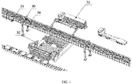
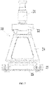
Fig. 1 shows a schematic structural view of a multimodal transportation interworking system in accordance with embodiments of the present invention; -
Fig. 2 shows a schematic structural view of a first embodiment of a rail system in a multimodal transportation interworking system in accordance with embodiments of the present invention; -
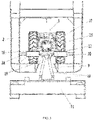
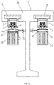
Fig. 3 shows a schematic structural view of a cargo vehicle bogie and a rail beam inFig. 2 ; -
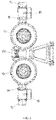
Fig. 4 shows a schematic top structural view of a cargo vehicle bogie inFig. 2 ; -
Fig. 5 shows a schematic right structural view of a cargo vehicle bogie inFig. 2 ; -
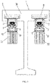
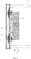
Fig. 6 shows a schematic front structural view of a suspension device of a second embodiment of a rail system in a multimodal transportation interworking system in accordance with embodiments of the present invention; -
Fig. 7 shows a schematic right structural view of a suspension device of a second embodiment of a rail system in a multimodal transportation interworking system in accordance with embodiments of the present invention; -
Fig. 8 shows a schematic front structural view of a third embodiment of a rail system in a multimodal transportation interworking system in accordance with embodiments of the present invention; -
Fig. 9 shows a schematic right structural view of a third embodiment of a rail system in a multimodal transportation interworking system in accordance with embodiments of the present invention; -
Fig. 10 shows a schematic structural view of a first transfer apparatus in a multimodal transportation interworking system in accordance with embodiments of the present invention; -
Fig. 11 shows a schematic structural view of a second transfer apparatus in a multimodal transportation interworking system in accordance with embodiments of the present invention; -
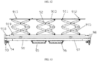
Fig. 12 shows a schematic structural view of a third transfer apparatus in a multimodal transportation interworking system in accordance with embodiments of the present invention; and -
Fig. 13 shows a front view of a third transfer apparatus in a multimodal transportation interworking system in accordance with embodiments of the present invention. - A multimodal transportation interworking system in accordance with embodiments of the present invention can achieve such technical effect as multimodal transportation between ports and railways, air logistics centers.
- To solve the foregoing technical problem, a technical solution according to embodiments of the present invention follows a general idea as below:
a rail system is provided to connect various ports with railways, air logistics centers, and a processor is provided to control a transfer apparatus to transfer a goods loading device and control a cargo vehicle to move on a rail beam after the goods loading device is secured onto the cargo vehicle. In this way, multimodal transportation between ports and railway, air logistics centers is achieved. In addition, by replacing road goods loading device transportation trucks with the rail system, not only the transport efficiency is increased, but also the pressure on the ground transportation is reduced and the environment is also protected. - To better understand the foregoing technical solution, detailed illustration is presented to the above technical solution in conjunction with the accompanying drawings and specific embodiments.
- With reference to
Fig. 1 , a multimodal transportation interworking system is provided according to embodiments of the present invention, at least comprising: - a
rail system 30; - a
cargo vehicle 31 disposed movably on a rail beam of therail system 30; - a
transfer apparatus 32 used for transferring agoods loading device 33 from a transportation tool to thecargo vehicle 31 and loading the same onto thecargo vehicle 31, or unloading thegoods loading device 33 from thecargo vehicle 31 and conveying the same onto the transportation tool; - a processor, which is connected to the
cargo vehicle 31 and thetransfer apparatus 32 so as to control thetransfer apparatus 32 to transfer thegoods loading device 33, and to control thecargo vehicle 31 to move on the rail beams after thegoods loading device 33 is secured onto thecargo vehicle 31. - In some embodiments, as the
goods loading device 33 needs to be transferred, thetransfer apparatus 32 transfers thegoods loading device 33 from a transportation tool to thecargo vehicle 31 and loads the same onto thecargo vehicle 31, and the processor controls thecargo vehicle 31 to move on the rail beams, or thetransfer apparatus 32 unloads thegoods loading device 33 from thecargo vehicle 31 and conveys the same onto the transportation tool. - With reference to
Figs. 2 and3 , a structure according to a first embodiment of the present invention comprises arail system 1 comprising arail pillar 30 and tworail beams 2. A lower surface of an upper portion of therail pillar 30 is bilaterally symmetrically provided with two C-shaped rail grooves 8, and the two rail grooves 8 run through from a front end to a rear end of therail system 1. Tworail beams 2 are mounted within the two rail grooves 8. Therail system 1 may be conveniently and stably disposed in isolation strips. In this embodiment, therail beams 2 are of a thin-walled steel box-type structure, and a lower surface of the rail beams 2 is provided with an opening 9 extending through from a front end to rear end thereof. Inner cavities of the tworail beams 2 are provided withmultiple cargo vehicles 31 that are movable within the rail beams 2. In this embodiment, the inner cavity of each of the rail beams 2 is provided with twocargo vehicles 31 which are supported on a lower surface of the inner cavity of therail beam 2. A lower end of thecargo vehicle 31 is connected with a goods loading device, which is thegoods loading device 33 in this embodiment. With reference toFigs. 4 and5 , thecargo vehicle 31 comprises acargo vehicle bogie 3, asuspension device 10 connected under thecargo vehicle bogie 3, as well as a goods loading device integratedspreader 11 connected under thesuspension device 10. A lower end of the goods loading device integratedspreader 11 is connected to thegoods loading device 33. The present embodiment adopts a super-capacitor power supply mode. Thecargo vehicle bogie 3 comprises abogie frame 12 that is in a welded structure. A front end and a rear end of thebogie frame 12 are connected with twogearboxes 13 by welding, respectively, and each of thegearboxes 13 is symmetrically provided with twooutput shafts 14 on left and right sides thereof, and a travellingwheel 15 is mounted on each of theoutput shafts 14. Thecargo vehicle bogie 3 runs on a lower surface of the inner cavity of therail beam 2 by means of four travellingwheels 15. The front and rear ends of the twogearboxes 13 are connected to two frameintermediate connections 16 by bolts respectively, and the front and rear ends of the two frameintermediate connections 16 are connected by bolts with housings of two tractionelectric motors 17 that control thecargo vehicle bogie 3 to run. A left side and a right side of the housing of each of the tractionelectric motors 17 are symmetrically welded with two guidewheel mounting seats 18 on a lower portion thereof, and guidewheels 19 are mounted on the two guidewheel mounting seats 18 respectively.Guide rails 20 are provided on left and right side walls of the inner cavity of therail beams 2 respectively, and the twoguide wheels 19 move back and forth along the twoguide rails 20, respectively. Each of the travellingwheels 15 and guidewheels 19 adopts rubber tires. A lower end of thebogie frame 12 is connected with the goods loading device integratedspreader 11 via thesuspension device 10, and a lower end of the goods loading device integratedspreader 11 is connected to thegoods loading device 33. - In use, the four
cargo vehicle bogies 3 travel on the tworail beams 2, thereby driving the twogoods loading devices 33 suspended under the fourcargo vehicle bogies 3 to move along a direction of the rail beams 2. The transportation of thegoods loading device 33 can be easily achieved through electric control. The four travellingwheels 15 of eachcargo vehicle bogie 3 guarantees a steady travel on therail beam 2, and the fourguide wheels 19 of eachcargo vehicle bogie 3 move back and forth along the guide rails 20 to effect the transportation of thegoods loading device 33. Theguide wheels 19 are provided to ensure that thecargo vehicle bogie 3 can steer steadily. All the travellingwheels 15 and theguide wheels 19 adopt rubber tires, so that an effect of shock absorption can be achieved when thecargo vehicle bogie 3 runs. At the same time, the adoption of rubber tires causes the vehicle have good acceleration and deceleration performance and stronger grade ability, reduces a noise of the vehicle and shock of the rail beams 2 , and is more adaptive to ports with complex topography. Therail system 1 may be disposed in isolation strips, andmultiple cargo vehicles 31 run on the tworail beams 2 in directions opposite to each other, respectively. Therefore, the air space is put into sufficient utilization, and no effect will be exerted on ground operations within the port, thus existing resources of docks can be utilized sufficiently for automation reformation, and problems such as dock congestion, lack of space and transport inefficiency can be solved. Thereby high-efficiency, low-cost and environment-friendly goods loading device quick and intelligent transport can be achieved, and meanwhile the transport system is simply structured, secure and reliable. Furthermore, the mountedrail beams 2 and the fourcargo vehicle bogies 3 have a simple and compact structure without occupying extra space, and the structure of the rail beams 2 is also simple and makes it convenient for thecargo vehicle bogies 3 to move securely thereon. In this embodiment, therail beam 2 may further be in a C-shaped channel steel structure, which also falls within the protection scope of the present invention. - A structure according to a second embodiment of the present invention comprises a
rail system 1 comprising arail pillar 30 and tworail beams 2. A lower surface of an upper portion of therail pillar 30 is bilaterally symmetrically provided with two C-shaped rail grooves 8, and the two rail grooves 8 run through from a front end to a rear end of therail system 1. Tworail beams 2 are mounted within the two rail grooves 8. Therail system 1 may be conveniently and stably disposed in isolation strips. In this embodiment, therail beams 2 are of a thin-walled steel box-type structure. A lower surface of the rail beams 2 is provided with an opening 9 extending through from a front end to a rear end thereof, and inner cavities of the tworail beams 2 are provided withmultiple cargo vehicles 31 that are movable within the rail beams 2. In this embodiment, the inner cavity of each of the rail beams 2 is provided with twocargo vehicles 31 which are supported at a lower surface of the inner cavity of the rail beams 2. With reference toFigs. 4 and5 , thecargo vehicle 31 comprises acargo vehicle bogie 3, asuspension device 10 connected under thecargo vehicle bogie 3, as well as a goods loading device integratedspreader 11 connected under thesuspension device 10. A lower end of the goods loading device integratedspreader 11 is connected with thegoods loading device 33. The present embodiment adopts a super-capacitor power supply mode. Thecargo vehicle bogie 3 comprises abogie frame 12 that is in a welded structure. A front end and a rear end of thebogie frame 12 are connected with twogearboxes 13 by welding respectively, and each of thegearboxes 13 is symmetrically provided with twooutput shafts 14 on left and right sides thereof, and a travellingwheel 15 is mounted on each of theoutput shafts 14. Thecargo vehicle bogie 3 runs on the lower surface of the inner cavity of therail beam 2 by means of four travellingwheels 15. Front and rear ends of the twogearboxes 13 are connected to two frameintermediate connections 16 by bolts respectively, and the front and rear ends of the two frameintermediate connections 16 are connected by bolts wtih housings of two tractionelectric motors 17 that control thecargo vehicle bogie 3 to run. A left side and a right side of the housing of each of the tractionelectric motors 17 are symmetrically welded with two guidewheel mounting seats 18 on a lower portion thereof, and guidewheels 19 are mounted on the two guidewheel mounting seats 18 respectively.Guide rails 20 are provided on left and right side walls of the inner cavity of therail beams 2 respectively, and the twoguide wheels 19 move back and forth along the twoguide rails 20, respectively. Each of the travellingwheels 15 and guidewheels 19 adopts rubber tires. A lower end of thebogie frame 12 is connected to the goods loading device integratedspreader 11 via thesuspension device 10 after passing through an opening 9, and a lower end of the goods loading device integratedspreader 11 is connected to thegoods loading device 33. With reference toFigs. 6 and7 , thesuspension device 10 comprises acenter pin 21 via which thesuspension device 10 is connected to a lower end of thebogie frame 12. A lower end of thecenter pin 21 is connected with aconnection seat 22 which is connected to twosuspension arms 24 via twofirst spindles 23, and thesuspension arm 24 is of a bending plate body. Lower ends of the twosuspension arms 24 are connected to a mountingseat 26 via twosecond spindles 25, and the mountingseat 26 is connected to the goods loading device integratedspreader 11. The processor is in a signal communication with the tractionelectric motor 17 to control a start or stop of the tractionelectric motor 17. - A working process and functions of the present embodiment is substantially same as those of the first embodiment, and thereby is not detailed here. In the present embodiment, by providing the
suspension device 10 as the foregoing structure, a force transmission by thecargo vehicle bogie 3 in three directions as X axis, Y axis and Z axis is achieved, and meanwhile, a relative movement between thegoods loading device 33 and thecargo vehicle bogie 3 is satisfied. - As shown in
Figs. 7 and8 which are a schematic front structural view and a schematic right structural view of a third embodiment of the present invention respectively. As depicted, the structure according to the third embodiment comprises arail system 1 comprising arail pillar 30 and tworail beams 2. A lower surface of an upper portion of therail pillar 30 is bilaterally symmetrically provided with two C-shaped rail grooves 8, and the two rail grooves 8 run through from a front end to a rear end of therail system 1. Tworail beams 2 are mounted within the two rail grooves 8. Therail system 1 may be conveniently and stably disposed in isolation strips. In this embodiment, therail beams 2 are of a thin-walled steel box-type structure, and a lower surface of the rail beams 2 is provided with an opening 9 extending through from a front end to rear end thereof. Inner cavities of the tworail beams 2 are provided withmultiple cargo vehicles 31 that are movable within the rail beams 2. In this embodiment, the inner cavity of each of the rail beams 2 is provided with twocargo vehicles 31 which are supported at a lower surface of the inner cavity of therail beam 2. With reference toFigs. 4 and5 , thecargo vehicle 31 comprises acargo vehicle bogie 3, asuspension device 10 connected under thecargo vehicle bogie 3, as well as a goods loading device integratedspreader 11 connected under thesuspension device 10. A lower end of the goods loading device integratedspreader 11 is connected to thegoods loading device 33. Thecargo vehicle bogie 3 comprises abogie frame 12 that is in a welded structure. A front end and a rear end of thebogie frame 12 are connected with twogearboxes 13 by welding, respectively, and each of thegearboxes 13 is symmetrically provided with twooutput shafts 14 on left and right sides thereof, and a travellingwheel 15 is mounted on each of theoutput shafts 14. Thecargo vehicle bogie 3 runs on a lower surface of the inner cavity of therail beam 2 by means of four travellingwheels 15. The front and rear ends of the twogearboxes 13 are connected to two frameintermediate connections 16 by bolts respectively, and the front and rear ends of the two frameintermediate connections 16 are connected by bolts with housings of two tractionelectric motors 17 that control thecargo vehicle bogie 3 to run. A left side and a right side of the housing of each of the tractionelectric motors 17 are symmetrically welded with two guidewheel mounting seats 18 on a lower portion thereof, and guidewheels 19 are mounted on the two guidewheel mounting seats 18 respectively.Guide rails 20 are provided on left and right side walls of the inner cavity of therail beams 2 respectively, and the twoguide wheels 19 move back and forth along the twoguide rails 20, respectively. Each of the travellingwheels 15 and guidewheels 19 adopts rubber tires. A lower end of thecargo vehicle bogie 3 is connected to the goods loading device integratedspreader 11 via thesuspension device 10 after passing through an opening 9, and a lower end of the goods loading device integratedspreader 11 is connected to thegoods loading device 33. With reference toFigs. 5 and6 , thesuspension device 10 comprises acenter pin 21 via which thesuspension device 10 is connected to a lower end of thebogie frame 12. A lower end of thecenter pin 21 is connected with aconnection seat 22 which is connected to twosuspension arms 24 via twofirst spindles 23, and thesuspension arm 24 is of a bending plate body. Lower ends of the twosuspension arms 24 are connected to a mountingseat 26 via twosecond spindles 25, and the mountingseat 26 is connected to the goods loading device integratedspreader 11. In the present embodiment, the goods loading device integratedspreader 11 comprises amain structure 27 made of steel rails, and the mountingseat 26 is welded on themain structure 27. A front portion and a rear portion of themain structure 27 are respectively provided with an energy-absorption anti-collision device 29 so as to prevent an impact on thecargo vehicle bogie 3 and guarantee a security of thecargo vehicle bogie 3 and the workinggoods loading device 33 in case of emergency. The energy-absorption anti-collision device 29 may also be mounted on an end of thecargo vehicle bogie 3, or anywhere. The present invention is not limited in this regard, and any position where the energy-absorption anti-collision device 29 is mounted falls within the protection scope of the present invention. Safety cables are reserved between thecargo vehicle bogie 3 and thegoods loading device 33, so as to guarantee thecargo vehicle 3 working securely, even if thecargo vehicle 3 is accidentally dropped in case of thesuspension device 10 being out of work. Apower supply system 28 is further included that supplies power to thecargo vehicle bogie 3. Thepower supply system 28 adopts a super-capacitor supply mode and is connected between therail system 1 and themain structure 27 of the goods loading device integratedspreader 11. - Embodiments of the present invention provide three structures of a
transfer apparatus 32. - With reference to
Fig. 10 , afirst transfer apparatus 32 at least comprises a conveyance mechanism, a grab mechanism and a lift mechanism. The grab mechanism places thegoods loading device 33 on the conveyance mechanism. The conveyance mechanism transports thegoods loading device 33 to the lift mechanism, and the lift mechanism lifts or lowers thegoods loading device 33. Thegoods loading device 33 is loaded onto or unloaded from thecargo vehicle 31. A processor is communicatively connected with the conveyance mechanism, the grab mechanism and the lift mechanism. - A structure of the conveyance mechanism is illustrated. The conveyance mechanism at least comprises a
first frame 71, a chain, a first group ofrotation shafts 72 and a power outputting device. The first group ofrotary shafts 72 is disposed on thefirst frame 71. Each rotation shaft of the first group ofrotation shafts 72 is provided with gears on which the chain is fitted around to drive each rotation shaft of the first group ofrotation shafts 72 to rotate, and the power output end of the power outputting device is connected to the chain to drive a rotation of the chain. - In the present embodiment, the power outputting device is an electric motor∘
- A structure of the lift mechanism is illustrated. The lift mechanism at least comprises a
telescopic mechanism 73 and a base, and a telescopic end of thetelescopic mechanism 73 is connected to the base. - A structure of the base is illustrated. The base at least comprises a
second frame 74 and a second group ofrotation shafts 75. A telescopic end of thetelescopic mechanism 73 is connected to thesecond frame 74, and the second group ofrotation shafts 75 is disposed on thesecond frame 74. - The structure of the base is further illustrated. The base further comprises at least a sensing element for sensing whether the
goods loading device 33 reaches a predefined position, and the sensing element is disposed on the base. A signal output end of the sending element is connected to a signal input end of the processor. - In the present embodiment, the sensing element comprises a displacement sensor and/or an infrared sensor.
- A structure of the grab mechanism is illustrated. The grab mechanism at least comprises a
telescopic arm 76, afirst support rod 77, asecond support rod 78, a firsttelescopic rod 79, a secondtelescopic rod 710, a thirdtelescopic rod 711 and aspreader 712. A first end of thefirst support rod 77 is fixedly connected to thefirst frame 71,and a second end of thefirst support rod 77 is hinged to a first end of thesecond support rod 78. A second end of thesecond support rod 78 is hinged to thetelescopic arm 76. A first end of the firsttelescopic rod 79 is fixedly connected to thefirst frame 71, and a second end of the firsttelescopic rod 79 is hinged to thesecond support rod 78. A first end of the secondtelescopic rod 710 is hinged to the first end of thesecond support rod 78, and a second end of the secondtelescopic rod 710 is hinged to a first end of thetelescopic arm 76. A first end of the thirdtelescopic rod 711 is fixedly connected to the first end of thetelescopic arm 76, and a second end of the thirdtelescopic rod 711 is fixedly connected to a second end of thetelescopic arm 76. The second end of thetelescopic arm 76 is connected to thespreader 712. - In the present embodiment, the first
telescopic rod 79, the secondtelescopic rod 710 and the thirdtelescopic rod 711 may be pneumatic rods or hydraulic rods, and the present embodiment does not limit how the telescopic rod is driven. - With reference to
Fig. 11 , asecond transfer apparatus 800 at least comprises a grab mechanism and a lift mechanism. The grab mechanism places the goods loading device on the lift mechanism, and the lift mechanism lifts or lowers the goods loading device. A processor is communicatively connected to the conveyance mechanism, the grab mechanism and the lift mechanism. - A structure of the lift mechanism is illustrated. The lift mechanism at least comprises a
telescopic mechanism 83 and a base, and a telescopic end of thetelescopic mechanism 83 is connected to the base. - A structure of the base is illustrated. The base at least comprises a
frame 84 and a support table 85. A telescopic end of thetelescopic mechanism 83 is connected to theframe 84, and the support table 85 is disposed on theframe 84. - The structure of the base is further illustrated. The base further comprises at least a sensing element for sensing whether the goods loading device reaches a predefined position, and the sensing element is disposed on the base. A signal output end of the sensing element is connected to a signal input end of the processor.
- In the present embodiment, the sensing element comprises a displacement sensor and/or an infrared sensor.
- The structure of the lift mechanism is further illustrated. The lift mechanism further comprises at least: a distance measuring element for sensing an extension amount of the
telescopic mechanism 83. The distance measuring element is disposed on thetelescopic mechanism 83 and/or the base. - A structure of the grab mechanism is illustrated. The grab mechanism at least comprises a
telescopic arm 86, afirst support rod 87, asecond support rod 88, a firsttelescopic rod 89, a secondtelescopic rod 810, a thirdtelescopic rod 811 and aspreader 812. A first end of thefirst support rod 87 is fixedly connected to the first frame 81, and a second end of thefirst support rod 87 is hinged to a first end of thesecond support rod 88. A second end of thesecond support rod 88 is hinged to thetelescopic arm 86. A first end of the firsttelescopic rod 89 is fixedly connected to the first frame 81, and a second end of the firsttelescopic rod 89 is hinged to thesecond support rod 88. A first end of the secondtelescopic rod 810 is hinged to the first end of thesecond support rod 88, and a second end of the secondtelescopic rod 810 is hinged to a first end of thetelescopic arm 86. A first end of the thirdtelescopic rod 811 is fixedly connected to the first end of thetelescopic arm 86, and a second end of the thirdtelescopic rod 811 is fixedly connected to a second end of thetelescopic arm 86. The second end of thetelescopic arm 86 is connected to thespreader 812. - In the present embodiment, the first
telescopic rod 89, the secondtelescopic rod 810 and the thirdtelescopic rod 811 may be pneumatic rods or hydraulic rods, and the present embodiment of the invention does not limit how the telescopic rod is driven. - To achieve an automation functionality of embodiments of the present invention, at least a controller is further provided. A signal input end of the controller is communicatively connected to signal output ends of the sensing element and the distance measuring element, and a signal output end of the controller is communicatively connected to signal input ends of the
telescopic mechanism 83, the firsttelescopic rod 89, the secondtelescopic rod 810, the thirdtelescopic rod 811 and thespreader 812. The controller controls thetelescopic mechanism 83, the firsttelescopic rod 89, the secondtelescopic rod 810, the thirdtelescopic rod 811 and thespreader 812 to work as required. - With reference to
Figs. 12 and13 , a third transfer apparatus comprises anunderframe 99, alifting device 92, a lifting table 910, alifting driving device 914,multiple travel wheels 93, atravel driving device 94, and atranslation device 917. - The lifting
device 92 is connected between theunderframe 99 and the lifting table 910; - the
lift driving device 914 is connected to thelifting device 92, for driving thelifting device 92 to lift or lower the lifting table; - the
multiple travel wheels 93 are fixed under theunderframe 99; - the
travel driving device 94 is fixed onto theunderframe 99 and connected to thetravel wheels 93 for driving a rotation of thetravel wheels 93; - the processor is communicatively connected to the
lift driving device 914 and thetravel driving device 94. - In the present embodiment, a surface of the lifting table 910 which is opposite to the
lifting device 92 is provided with a first group oflocks 911 and a second group oflocks 912 which are snap-fasten to a bottom of thegoods loading device 33. The second group of locks is located external to the first group oflocks 911 and has a higher height than the first group oflocks 911. Two ends of the surface of the lifting table 910 which is opposite to thelifting device 92 are provided with two protrudingbeams 913, and the second group oflocks 912 is disposed on the two protrudingbeams 913. The first group oflocks 911 and the second group oflocks 912 consist of four embosses, respectively. - A structure of the
underframe 99 is illustrated. Theunderframe 99 comprises at least twoend beams 98, at least twoside beams 97, a plurality of crossbeams and abottom plate 916. Two ends of the at least twoend beams 98 are connected to two ends of the at least twoside beams 97, respectively. The plurality of crossbeams are disposed between the at least twoend beams 98, and two ends thereof are connected to the at least twoside beams 97, respectively. Thebottom plate 916 is fixed onto the at least twoend beams 98, the at least twoside beams 97 and the plurality of crossbeams. In other embodiments, thebottom plate 916 may not be provided. Further, in the present embodiment, a travelling direction of themultiple travel wheels 93 is parallel to a length direction of the end beams 98. - The
travel wheel 93 may be provided as a rubber wheel or a universal wheel, and a kinetic energy of the transfer device may be provided by a super capacitor, and a quick charging pile may be arranged at a start position or a specified position. - To achieve an alarm functionality, embodiments of the present invention at least may further comprise an alarm apparatus, and a signal input end of the alarm apparatus is communicatively connected to a signal output end of the processor.
- A goods loading device transfer operation procedure for transporting a
goods loading device 33 from a port goods loading device dock to a railway, road or air logistics center and other goods loading device logistics center according to embodiments of the present invention is as below: - (1) a grab mechanism of a
transfer apparatus 32 at a shipment place receives a C0001# goods loading device 33 (it is assumed that thegoods loading device 33 is numbered as C0001#) from a dockside loading and unloading crane at a port goods loading device dock, and the C0001#goods loading device 33 is transported by a conveyance mechanism of thetransfer apparatus 32 to a loading & unloading place for goods loading devices where a cargo vehicle stops within a short distance, and then a lift mechanism of thetransfer apparatus 32 lifts the C0001#goods loading device 33 to an appropriate height; - (2) the
cargo vehicle 31 on therail system 30 is controlled by a processor to run to the loading & unloading place, and aspreader 29 of thecargo vehicle 31 is utilized to grab the C0001#goods loading device 33 and automatically transport the same along the rail beam to a specified unloading place for goods loading devices in a multimodal transport logistics center; - (3) the C0001#
goods loading device 33 is received from thecargo vehicle 31 by the lift mechanism of thetransfer apparatus 32 at the unloading place and transferred by the conveyance mechanism and the grab mechanism of thetransfer apparatus 32 to a road container truck or a railway goods loading device transport vehicle which stops at the unloading place in advance. At this point, the procedure for transporting the C0001#goods loading device 33 from the port to the multimodal transport logistics center according to embodiments of the present invention ends. - By means of embodiments of the present invention, a
goods loading device 33 may also be transported from a railway, road or air goods loading device logistics center to a port goods loading device dock, a specific operation procedure of which is in a reverse order with respect to the foregoing operation procedure and thereby is not illustrated here. - By a
rail system 30 connecting various ports with railway and air logistics centers, and a processor controlling atransfer apparatus 32 to transfer agoods loading device 33 and controlling acargo vehicle 31 to move on therail system 30 after thegoods loading device 33 is secured onto thecargo vehicle 31, a multimodal transport between ports and railway, air logistics centers is achieved. In addition, by replacing road goods loading device transport trucks with the rail system, not only a transportation efficiency is increased, but also a pressure on the ground transportation is reduced and the environment is also protected. - By means of a
sky rail system 30 according to embodiments of the present invention, interconnecting and interworking between various goods loading device distribution centers may be achieved, and harmonious connection between rail, water, road and air logistics systems is realized, completely meeting "zero-distance transfer and seamless connection" requirements, and sufficiently releasing the ground transportation capacity. Embodiments of the present invention completely conform to the national strategy on vigorous development of multimodal transport and provide an overall solution for intelligent and efficient transfer of goods loading device multimodal transport. - While the preferred embodiments of the present invention have been described, those skilled in the art may make other alterations and modifications to these embodiments once learning the basic creative concept. Therefore, the claims as appended are intended to be construed as including the preferred embodiments and all alterations and modifications which fall within the scope of the present invention.
- The scope of protection is defined by the appended claims.
Claims (7)
- A multimodal transportation interworking system, at least comprising:a rail system (1, 30);a cargo vehicle (31) movably disposed on a rail beam of the rail system (1, 30);a transfer apparatus (32) used for transferring a goods loading device (33) from a transportation tool to the cargo vehicle (31) and loading the goods loading device (33) onto the cargo vehicle (31), or unloading the goods loading device (33) from the cargo vehicle (31) and conveying the goods loading device (33) onto the transportation tool;a processor connected to the cargo vehicle (31) and the transfer apparatus (32) so as to control the transfer apparatus (32) to transfer the goods loading device (33), and to control the cargo vehicle (31) to move on the rail beam after the goods loading device (33) is secured onto the cargo vehicle (31);wherein, as the goods loading device (33) needs to be transferred, the transfer apparatus (32) transfers the goods loading device (33) from the transportation tool to the cargo vehicle (31) and loads the goods loading device (33) onto the cargo vehicle (31), and the processor controls the cargo vehicle (31) to move on the rail beam, or the transfer apparatus (32) unloads the goods loading device (33) from the cargo vehicle (31) and conveys the goods loading device (33) onto the transportation tool;characterised in thateach of the cargo vehicles (31) comprises a cargo vehicle bogie (3) being supported at the lower surface of the inner cavity of the rail beams (2), the cargo vehicle bogie (3) comprising a bogie frame (12) whose front and rear ends are connected with gearboxes (13) respectively, each of the gearboxes (13) being symmetrically provided with two output shafts (14) on left and right sides, a travelling wheel (15) being mounted on each of the output shafts (14), the cargo vehicle bogie (3) running on the rail beams (2) by four travelling wheels (15), front and rear ends of two gearboxes (13) being connected to two frame intermediate connections (16) respectively, front and rear ends of the two frame intermediate connections (16) being respectively connected to two traction electric motors (17) which control the cargo vehicle bogie (3) to run, a lower end of the cargo vehicle bogie (3) being connected to a goods loading device (33) integrated spreader via a suspension device (10) after passing through the opening (9), a lower end of the goods loading device (33) integrated spreader being connected to the goods loading device (33); the processor is connected to the traction electric motor (17),wherein the rail system (1) is bilaterally symmetrically mounted with two rail beams (2), the two rail beams (2) being respectively provided with a plurality of cargo vehicles (31) which are movable thereon, the goods loading device (33) being suspended on a lower end of the plurality of cargo vehicles (31) below the rail beam at each side,wherein the rail beams (2) are of a box-type structure, a lower surface of the rail beams (2) being provided with an opening (9) which extends through from a front end to a rear end thereof, the cargo vehicle (31) being supported at a lower surface of an inner cavity of the rail beams (2).
- The system of claim 1, wherein a left side and a right side of a housing of each of the traction electric motors (17) are symmetrically connected with two guide wheel mounting seats (18) on a lower portion thereof, guide wheels (19) being mounted on the two guide wheel mounting seats (18) respectively, guide rails (20) being provided on left and right side walls of the opening (9) of the rail beams (2) respectively, the two guide wheels (19) moving along the two guide rails (20) respectively.
- The system of claim 2, wherein the suspension device (10) comprises a center pin (21), an upper end of the center pin (21) being connected to a lower end of the bogie frame (12), a lower end of the center pin (21) being connected with a connection seat (22) which is connected to two suspension arms (24) via multiple first spindles (23), lower ends of the two suspension arms (24) being connected to a mounting seat (26) via multiple second spindles (25), the mounting seat (26) being connected to the goods loading device integrated spreader (11).
- The system of claim 1, wherein the transfer apparatus (32) at least comprises: a conveyance mechanism, a grab mechanism and a lift mechanism; the grab mechanism suitable for placing the goods loading device (33) on the conveyance mechanism; the conveyance mechanism suitable for transporting the goods loading device (33) to the lift mechanism; the lift mechanism suitable for lifting or lowering the goods loading device (33); the goods loading device (33) suitable to be loaded onto or unloaded from the cargo vehicle (31); the processor being communicatively connected to the conveyance mechanism, the grab mechanism and the lift mechanism.
- The system of claim 4, wherein the conveyance mechanism at least comprises: a first frame (71), a chain, a first group of rotation shafts (72) and a power outputting device; the first group of rotation shafts (72) is disposed on the first frame (71); each rotation shaft of the first group of rotation shafts (72) is provided with gears; the chain is fitted around the gears to drive each rotation shaft of the first group of rotation shafts (72) to rotate; a power output end of the power outputting device is connected to the chain.
- The system of claim 4, wherein the grab mechanism at least comprises: a telescopic arm (76), a first support rod (77), a second support rod (78), a first telescopic rod (79), a second telescopic rod (710), a third telescopic rod (711) and a spreader (712); a first end of the first support rod (77) is fixedly connected to the first frame (71), and a second end of the first support rod (77) is hinged to a first end of the second support rod (78); a second end of the second support rod (78) is hinged to the telescopic arm (76); a first end of the first telescopic rod (79) is fixedly connected to the first frame (71), and a second end of the first telescopic rod (79) is hinged to the second support rod (78); a first end of the second telescopic rod (710) is hinged to the first end of the second support rod (78), and a second end of the second telescopic rod (710) is hinged to a first end of the telescopic arm (76); a first end of the third telescopic rod (711) is fixedly connected to the first end of the telescopic arm (76), and a second end of the third telescopic rod (711) is fixedly connected to a second end of the telescopic arm (76); the second end of the telescopic arm (76) is connected to the spreader (712).
- The system of claim 1, wherein the transfer apparatus (32) comprises: an underframe (99), a lifting device (92), a lifting table (910), a lift driving device (914), a plurality of travel wheels (93) and a travel driving device (94);the lifting device (92) is connected between the underframe (99) and the lifting table (910);the lift driving device (914) is connected to the lifting device (92) for driving the lifting device (92) to lift or lower the lifting table (910);the plurality of travel wheels (93) are fixed under the underframe (99);the travel driving device (94) is fixed onto the underframe (99) and connected to the travel wheels (93) for driving a rotation of the travel wheels (93);the processor is communicatively connected to the lift driving device (914) and the travel driving device (94).
Applications Claiming Priority (3)
| Application Number | Priority Date | Filing Date | Title |
|---|---|---|---|
| CN201610937619.4A CN106516779B (en) | 2016-10-24 | 2016-10-24 | A kind of multimodal transport intercommunicating system |
| CN201621160102.0U CN206486008U (en) | 2016-10-24 | 2016-10-24 | A kind of multimodal transport intercommunicating system |
| PCT/CN2017/094307 WO2018076834A1 (en) | 2016-10-24 | 2017-07-25 | Multimodal transport interworking system |
Publications (3)
| Publication Number | Publication Date |
|---|---|
| EP3428094A1 EP3428094A1 (en) | 2019-01-16 |
| EP3428094A4 EP3428094A4 (en) | 2019-11-27 |
| EP3428094B1 true EP3428094B1 (en) | 2022-12-07 |
Family
ID=62023088
Family Applications (1)
| Application Number | Title | Priority Date | Filing Date |
|---|---|---|---|
| EP17865533.8A Active EP3428094B1 (en) | 2016-10-24 | 2017-07-25 | Multimodal transport interworking system |
Country Status (6)
| Country | Link |
|---|---|
| US (1) | US11097749B2 (en) |
| EP (1) | EP3428094B1 (en) |
| AU (1) | AU2017348144B2 (en) |
| SG (1) | SG11201807460UA (en) |
| WO (1) | WO2018076834A1 (en) |
| ZA (1) | ZA201903264B (en) |
Families Citing this family (4)
| Publication number | Priority date | Publication date | Assignee | Title |
|---|---|---|---|---|
| WO2018076834A1 (en) * | 2016-10-24 | 2018-05-03 | 中车长江车辆有限公司 | Multimodal transport interworking system |
| CN111232639A (en) * | 2020-03-17 | 2020-06-05 | 中建材凯盛机器人(上海)有限公司 | Automatic loading device of shipment integral type material |
| CN111453448B (en) * | 2020-04-20 | 2022-02-18 | 中车长江车辆有限公司 | Operation method and system for converting highway-railway combined transport mode of railway station yard |
| CN111762233A (en) * | 2020-06-03 | 2020-10-13 | 中铁武汉勘察设计研究院有限公司 | Safety protection system and method for molten iron combined transport vehicle handover |
Family Cites Families (16)
| Publication number | Priority date | Publication date | Assignee | Title |
|---|---|---|---|---|
| IL104578A (en) | 1993-02-01 | 1995-07-31 | Mind E M S G Ltd | Transcontinental transport system |
| DE4332232C1 (en) | 1993-09-22 | 1995-02-02 | Klaus Schroeder | Apparatus for the rapid transfer of transporting vessels |
| DE19533256A1 (en) | 1995-09-08 | 1997-04-30 | Krupp Foerdertechnik Gmbh | Method and device for handling cargo between rail and road vehicles |
| EP0831002A1 (en) * | 1996-09-24 | 1998-03-25 | MANNESMANN Aktiengesellschaft | Apparatus for horizontal transfer of loads |
| DE29922538U1 (en) | 1999-12-22 | 2001-05-03 | AUTEFA Automation GmbH, 86316 Friedberg | Distribution device for goods |
| ITMI20020337A1 (en) * | 2002-02-20 | 2003-08-20 | Guido Porta | RAILWAY TRANSPORT METHOD AND EQUIPMENT FOR THE LOADING AND DISCHARGE OF CONVEYORS |
| US8746153B2 (en) * | 2005-09-28 | 2014-06-10 | Leonard D. Barry | Go-between container transfer and system |
| US8585347B2 (en) | 2007-06-26 | 2013-11-19 | Mi-Jack Products, Inc. | Hub and distribution system |
| CN201296509Y (en) | 2008-09-01 | 2009-08-26 | 高建飞 | Three-track heavy-duty power and free conveying equipment |
| JP5581048B2 (en) * | 2009-12-21 | 2014-08-27 | 株式会社岡村製作所 | Article conveying device |
| WO2014105862A1 (en) * | 2012-12-28 | 2014-07-03 | Frost Tech Llc | High capacity conveyor trolley and method |
| ES2622469B2 (en) * | 2016-01-06 | 2018-03-08 | Antonio Marcos RUIZ VEGA | PROCEDURE FOR THE TRANSFER OF STANDARDIZED CONTAINERS BETWEEN A CONTAINER VESSEL AND A SPRING |
| CN206486008U (en) | 2016-10-24 | 2017-09-12 | 中车长江车辆有限公司 | A kind of multimodal transport intercommunicating system |
| SG11201807459VA (en) * | 2016-10-24 | 2018-09-27 | Crrc Yangtze Co Ltd | Straddle-type multimodal transport interconnecting system |
| WO2018076834A1 (en) * | 2016-10-24 | 2018-05-03 | 中车长江车辆有限公司 | Multimodal transport interworking system |
| CN106516779B (en) | 2016-10-24 | 2018-01-23 | 中车长江车辆有限公司 | A kind of multimodal transport intercommunicating system |
-
2017
- 2017-07-25 WO PCT/CN2017/094307 patent/WO2018076834A1/en active Application Filing
- 2017-07-25 US US16/343,795 patent/US11097749B2/en active Active
- 2017-07-25 SG SG11201807460UA patent/SG11201807460UA/en unknown
- 2017-07-25 AU AU2017348144A patent/AU2017348144B2/en active Active
- 2017-07-25 EP EP17865533.8A patent/EP3428094B1/en active Active
-
2019
- 2019-05-23 ZA ZA2019/03264A patent/ZA201903264B/en unknown
Also Published As
| Publication number | Publication date |
|---|---|
| US20190251510A1 (en) | 2019-08-15 |
| SG11201807460UA (en) | 2018-09-27 |
| BR112018069264A2 (en) | 2022-08-30 |
| WO2018076834A1 (en) | 2018-05-03 |
| AU2017348144A1 (en) | 2019-06-06 |
| US11097749B2 (en) | 2021-08-24 |
| EP3428094A4 (en) | 2019-11-27 |
| ZA201903264B (en) | 2020-03-25 |
| AU2017348144B2 (en) | 2020-09-24 |
| EP3428094A1 (en) | 2019-01-16 |
Similar Documents
| Publication | Publication Date | Title |
|---|---|---|
| EP3428093B1 (en) | Aerial railway-based multimodal transport interconnecting system | |
| EP3428094B1 (en) | Multimodal transport interworking system | |
| EP1847492B1 (en) | Arrangement scheme of a container wharf and the container loading/unloading process | |
| CN106516779B (en) | A kind of multimodal transport intercommunicating system | |
| CN106564764B (en) | A kind of multimodal transport intercommunicating system | |
| KR20030018003A (en) | System for transporting and skew loading/unloading of cars in a combined railway/road transport railway station and method for using same | |
| CN109878402B (en) | AGV transport vehicle for transporting railway carriage | |
| CN109911786B (en) | Container rapid transfer system and method for logistics node station | |
| CN206486008U (en) | A kind of multimodal transport intercommunicating system | |
| CN202116053U (en) | Automatic transportation line for container loading and unloading | |
| CN106627603A (en) | Multimodal transport interworking control system | |
| WO2024037246A1 (en) | Loading and unloading apparatus of hanger container transport system | |
| CN104444956A (en) | Lift truck for loading and unloading cargos | |
| JP2022528449A (en) | Multifunctional freight transfer vehicle and method | |
| CN107053979A (en) | Combined automatic transfer vehicle | |
| CN209972287U (en) | AGV (automatic guided vehicle) for transporting railway carriage | |
| EP3428092B1 (en) | Straddle-type multimodal transport interconnecting system | |
| CN209797331U (en) | Quick transfer system of container at commodity circulation node station | |
| CN204298020U (en) | A kind of handling goods lift car | |
| CN110127400B (en) | Multi-type combined transport loading and unloading equipment and loading and unloading method thereof | |
| CN206466734U (en) | A kind of multimodal transport intercommunicating system | |
| CN113879350B (en) | Male and rail intermodal transportation system and railway transportation vehicle | |
| US20200406942A1 (en) | Rail and Train System | |
| CN117945188A (en) | Container train loading and unloading system and method | |
| BR112018069264B1 (en) | INTEROPERATED MULTIMODAL TRANSPORTATION SYSTEM |
Legal Events
| Date | Code | Title | Description |
|---|---|---|---|
| STAA | Information on the status of an ep patent application or granted ep patent |
Free format text: STATUS: THE INTERNATIONAL PUBLICATION HAS BEEN MADE |
|
| PUAI | Public reference made under article 153(3) epc to a published international application that has entered the european phase |
Free format text: ORIGINAL CODE: 0009012 |
|
| STAA | Information on the status of an ep patent application or granted ep patent |
Free format text: STATUS: REQUEST FOR EXAMINATION WAS MADE |
|
| 17P | Request for examination filed |
Effective date: 20181012 |
|
| AK | Designated contracting states |
Kind code of ref document: A1 Designated state(s): AL AT BE BG CH CY CZ DE DK EE ES FI FR GB GR HR HU IE IS IT LI LT LU LV MC MK MT NL NO PL PT RO RS SE SI SK SM TR |
|
| AX | Request for extension of the european patent |
Extension state: BA ME |
|
| STAA | Information on the status of an ep patent application or granted ep patent |
Free format text: STATUS: REQUEST FOR EXAMINATION WAS MADE |
|
| A4 | Supplementary search report drawn up and despatched |
Effective date: 20191025 |
|
| RIC1 | Information provided on ipc code assigned before grant |
Ipc: B61B 13/06 20060101ALI20191021BHEP Ipc: B61B 3/00 20060101ALI20191021BHEP Ipc: B61D 47/00 20060101ALI20191021BHEP Ipc: B65G 63/04 20060101AFI20191021BHEP |
|
| REG | Reference to a national code |
Ref country code: HK Ref legal event code: DE Ref document number: 1262421 Country of ref document: HK |
|
| DAV | Request for validation of the european patent (deleted) | ||
| DAX | Request for extension of the european patent (deleted) | ||
| STAA | Information on the status of an ep patent application or granted ep patent |
Free format text: STATUS: EXAMINATION IS IN PROGRESS |
|
| 17Q | First examination report despatched |
Effective date: 20210507 |
|
| STAA | Information on the status of an ep patent application or granted ep patent |
Free format text: STATUS: EXAMINATION IS IN PROGRESS |
|
| GRAP | Despatch of communication of intention to grant a patent |
Free format text: ORIGINAL CODE: EPIDOSNIGR1 |
|
| STAA | Information on the status of an ep patent application or granted ep patent |
Free format text: STATUS: GRANT OF PATENT IS INTENDED |
|
| INTG | Intention to grant announced |
Effective date: 20220801 |
|
| GRAS | Grant fee paid |
Free format text: ORIGINAL CODE: EPIDOSNIGR3 |
|
| GRAA | (expected) grant |
Free format text: ORIGINAL CODE: 0009210 |
|
| STAA | Information on the status of an ep patent application or granted ep patent |
Free format text: STATUS: THE PATENT HAS BEEN GRANTED |
|
| AK | Designated contracting states |
Kind code of ref document: B1 Designated state(s): AL AT BE BG CH CY CZ DE DK EE ES FI FR GB GR HR HU IE IS IT LI LT LU LV MC MK MT NL NO PL PT RO RS SE SI SK SM TR |
|
| REG | Reference to a national code |
Ref country code: GB Ref legal event code: FG4D |
|
| REG | Reference to a national code |
Ref country code: CH Ref legal event code: EP Ref country code: AT Ref legal event code: REF Ref document number: 1536202 Country of ref document: AT Kind code of ref document: T Effective date: 20221215 |
|
| REG | Reference to a national code |
Ref country code: DE Ref legal event code: R096 Ref document number: 602017064484 Country of ref document: DE |
|
| REG | Reference to a national code |
Ref country code: IE Ref legal event code: FG4D |
|
| REG | Reference to a national code |
Ref country code: SE Ref legal event code: TRGR |
|
| REG | Reference to a national code |
Ref country code: LT Ref legal event code: MG9D |
|
| REG | Reference to a national code |
Ref country code: NL Ref legal event code: MP Effective date: 20221207 |
|
| PG25 | Lapsed in a contracting state [announced via postgrant information from national office to epo] |
Ref country code: NO Free format text: LAPSE BECAUSE OF FAILURE TO SUBMIT A TRANSLATION OF THE DESCRIPTION OR TO PAY THE FEE WITHIN THE PRESCRIBED TIME-LIMIT Effective date: 20230307 Ref country code: LT Free format text: LAPSE BECAUSE OF FAILURE TO SUBMIT A TRANSLATION OF THE DESCRIPTION OR TO PAY THE FEE WITHIN THE PRESCRIBED TIME-LIMIT Effective date: 20221207 Ref country code: FI Free format text: LAPSE BECAUSE OF FAILURE TO SUBMIT A TRANSLATION OF THE DESCRIPTION OR TO PAY THE FEE WITHIN THE PRESCRIBED TIME-LIMIT Effective date: 20221207 Ref country code: ES Free format text: LAPSE BECAUSE OF FAILURE TO SUBMIT A TRANSLATION OF THE DESCRIPTION OR TO PAY THE FEE WITHIN THE PRESCRIBED TIME-LIMIT Effective date: 20221207 |
|
| REG | Reference to a national code |
Ref country code: AT Ref legal event code: MK05 Ref document number: 1536202 Country of ref document: AT Kind code of ref document: T Effective date: 20221207 |
|
| PG25 | Lapsed in a contracting state [announced via postgrant information from national office to epo] |
Ref country code: RS Free format text: LAPSE BECAUSE OF FAILURE TO SUBMIT A TRANSLATION OF THE DESCRIPTION OR TO PAY THE FEE WITHIN THE PRESCRIBED TIME-LIMIT Effective date: 20221207 Ref country code: PL Free format text: LAPSE BECAUSE OF FAILURE TO SUBMIT A TRANSLATION OF THE DESCRIPTION OR TO PAY THE FEE WITHIN THE PRESCRIBED TIME-LIMIT Effective date: 20221207 Ref country code: LV Free format text: LAPSE BECAUSE OF FAILURE TO SUBMIT A TRANSLATION OF THE DESCRIPTION OR TO PAY THE FEE WITHIN THE PRESCRIBED TIME-LIMIT Effective date: 20221207 Ref country code: HR Free format text: LAPSE BECAUSE OF FAILURE TO SUBMIT A TRANSLATION OF THE DESCRIPTION OR TO PAY THE FEE WITHIN THE PRESCRIBED TIME-LIMIT Effective date: 20221207 Ref country code: GR Free format text: LAPSE BECAUSE OF FAILURE TO SUBMIT A TRANSLATION OF THE DESCRIPTION OR TO PAY THE FEE WITHIN THE PRESCRIBED TIME-LIMIT Effective date: 20230308 |
|
| P01 | Opt-out of the competence of the unified patent court (upc) registered |
Effective date: 20230515 |
|
| PG25 | Lapsed in a contracting state [announced via postgrant information from national office to epo] |
Ref country code: NL Free format text: LAPSE BECAUSE OF FAILURE TO SUBMIT A TRANSLATION OF THE DESCRIPTION OR TO PAY THE FEE WITHIN THE PRESCRIBED TIME-LIMIT Effective date: 20221207 |
|
| PG25 | Lapsed in a contracting state [announced via postgrant information from national office to epo] |
Ref country code: SM Free format text: LAPSE BECAUSE OF FAILURE TO SUBMIT A TRANSLATION OF THE DESCRIPTION OR TO PAY THE FEE WITHIN THE PRESCRIBED TIME-LIMIT Effective date: 20221207 Ref country code: RO Free format text: LAPSE BECAUSE OF FAILURE TO SUBMIT A TRANSLATION OF THE DESCRIPTION OR TO PAY THE FEE WITHIN THE PRESCRIBED TIME-LIMIT Effective date: 20221207 Ref country code: PT Free format text: LAPSE BECAUSE OF FAILURE TO SUBMIT A TRANSLATION OF THE DESCRIPTION OR TO PAY THE FEE WITHIN THE PRESCRIBED TIME-LIMIT Effective date: 20230410 Ref country code: EE Free format text: LAPSE BECAUSE OF FAILURE TO SUBMIT A TRANSLATION OF THE DESCRIPTION OR TO PAY THE FEE WITHIN THE PRESCRIBED TIME-LIMIT Effective date: 20221207 Ref country code: CZ Free format text: LAPSE BECAUSE OF FAILURE TO SUBMIT A TRANSLATION OF THE DESCRIPTION OR TO PAY THE FEE WITHIN THE PRESCRIBED TIME-LIMIT Effective date: 20221207 Ref country code: AT Free format text: LAPSE BECAUSE OF FAILURE TO SUBMIT A TRANSLATION OF THE DESCRIPTION OR TO PAY THE FEE WITHIN THE PRESCRIBED TIME-LIMIT Effective date: 20221207 |
|
| PG25 | Lapsed in a contracting state [announced via postgrant information from national office to epo] |
Ref country code: SK Free format text: LAPSE BECAUSE OF FAILURE TO SUBMIT A TRANSLATION OF THE DESCRIPTION OR TO PAY THE FEE WITHIN THE PRESCRIBED TIME-LIMIT Effective date: 20221207 Ref country code: IS Free format text: LAPSE BECAUSE OF FAILURE TO SUBMIT A TRANSLATION OF THE DESCRIPTION OR TO PAY THE FEE WITHIN THE PRESCRIBED TIME-LIMIT Effective date: 20230407 Ref country code: AL Free format text: LAPSE BECAUSE OF FAILURE TO SUBMIT A TRANSLATION OF THE DESCRIPTION OR TO PAY THE FEE WITHIN THE PRESCRIBED TIME-LIMIT Effective date: 20221207 |
|
| REG | Reference to a national code |
Ref country code: DE Ref legal event code: R097 Ref document number: 602017064484 Country of ref document: DE |
|
| PLBE | No opposition filed within time limit |
Free format text: ORIGINAL CODE: 0009261 |
|
| STAA | Information on the status of an ep patent application or granted ep patent |
Free format text: STATUS: NO OPPOSITION FILED WITHIN TIME LIMIT |
|
| PG25 | Lapsed in a contracting state [announced via postgrant information from national office to epo] |
Ref country code: DK Free format text: LAPSE BECAUSE OF FAILURE TO SUBMIT A TRANSLATION OF THE DESCRIPTION OR TO PAY THE FEE WITHIN THE PRESCRIBED TIME-LIMIT Effective date: 20221207 |
|
| PGFP | Annual fee paid to national office [announced via postgrant information from national office to epo] |
Ref country code: GB Payment date: 20230725 Year of fee payment: 7 Ref country code: CH Payment date: 20230801 Year of fee payment: 7 |
|
| 26N | No opposition filed |
Effective date: 20230908 |
|
| PG25 | Lapsed in a contracting state [announced via postgrant information from national office to epo] |
Ref country code: SI Free format text: LAPSE BECAUSE OF FAILURE TO SUBMIT A TRANSLATION OF THE DESCRIPTION OR TO PAY THE FEE WITHIN THE PRESCRIBED TIME-LIMIT Effective date: 20221207 |
|
| PGFP | Annual fee paid to national office [announced via postgrant information from national office to epo] |
Ref country code: SE Payment date: 20230721 Year of fee payment: 7 Ref country code: DE Payment date: 20230712 Year of fee payment: 7 Ref country code: BE Payment date: 20230721 Year of fee payment: 7 |
|
| PG25 | Lapsed in a contracting state [announced via postgrant information from national office to epo] |
Ref country code: MC Free format text: LAPSE BECAUSE OF FAILURE TO SUBMIT A TRANSLATION OF THE DESCRIPTION OR TO PAY THE FEE WITHIN THE PRESCRIBED TIME-LIMIT Effective date: 20221207 |
|
| PG25 | Lapsed in a contracting state [announced via postgrant information from national office to epo] |
Ref country code: MC Free format text: LAPSE BECAUSE OF FAILURE TO SUBMIT A TRANSLATION OF THE DESCRIPTION OR TO PAY THE FEE WITHIN THE PRESCRIBED TIME-LIMIT Effective date: 20221207 |
|
| PG25 | Lapsed in a contracting state [announced via postgrant information from national office to epo] |
Ref country code: LU Free format text: LAPSE BECAUSE OF NON-PAYMENT OF DUE FEES Effective date: 20230725 |
|
| PG25 | Lapsed in a contracting state [announced via postgrant information from national office to epo] |
Ref country code: LU Free format text: LAPSE BECAUSE OF NON-PAYMENT OF DUE FEES Effective date: 20230725 |
|
| REG | Reference to a national code |
Ref country code: IE Ref legal event code: MM4A |
|
| PG25 | Lapsed in a contracting state [announced via postgrant information from national office to epo] |
Ref country code: IT Free format text: LAPSE BECAUSE OF FAILURE TO SUBMIT A TRANSLATION OF THE DESCRIPTION OR TO PAY THE FEE WITHIN THE PRESCRIBED TIME-LIMIT Effective date: 20221207 |
|
| PG25 | Lapsed in a contracting state [announced via postgrant information from national office to epo] |
Ref country code: IE Free format text: LAPSE BECAUSE OF NON-PAYMENT OF DUE FEES Effective date: 20230725 |
|
| PG25 | Lapsed in a contracting state [announced via postgrant information from national office to epo] |
Ref country code: IE Free format text: LAPSE BECAUSE OF NON-PAYMENT OF DUE FEES Effective date: 20230725 |
|
| PGFP | Annual fee paid to national office [announced via postgrant information from national office to epo] |
Ref country code: FR Payment date: 20240619 Year of fee payment: 8 |