EP3427984B2 - Schutzvorrichtung für einen fahrzeuginnenraum - Google Patents
Schutzvorrichtung für einen fahrzeuginnenraum Download PDFInfo
- Publication number
- EP3427984B2 EP3427984B2 EP18177327.6A EP18177327A EP3427984B2 EP 3427984 B2 EP3427984 B2 EP 3427984B2 EP 18177327 A EP18177327 A EP 18177327A EP 3427984 B2 EP3427984 B2 EP 3427984B2
- Authority
- EP
- European Patent Office
- Prior art keywords
- protective device
- plug
- receptacles
- guide member
- sections
- Prior art date
- Legal status (The legal status is an assumption and is not a legal conclusion. Google has not performed a legal analysis and makes no representation as to the accuracy of the status listed.)
- Active
Links
Images


Classifications
-
- B—PERFORMING OPERATIONS; TRANSPORTING
- B60—VEHICLES IN GENERAL
- B60J—WINDOWS, WINDSCREENS, NON-FIXED ROOFS, DOORS, OR SIMILAR DEVICES FOR VEHICLES; REMOVABLE EXTERNAL PROTECTIVE COVERINGS SPECIALLY ADAPTED FOR VEHICLES
- B60J7/00—Non-fixed roofs; Roofs with movable panels, e.g. rotary sunroofs
- B60J7/02—Non-fixed roofs; Roofs with movable panels, e.g. rotary sunroofs of sliding type, e.g. comprising guide shoes
- B60J7/04—Non-fixed roofs; Roofs with movable panels, e.g. rotary sunroofs of sliding type, e.g. comprising guide shoes with rigid plate-like element or elements, e.g. open roofs with harmonica-type folding rigid panels
- B60J7/043—Sunroofs e.g. sliding above the roof
-
- B—PERFORMING OPERATIONS; TRANSPORTING
- B60—VEHICLES IN GENERAL
- B60J—WINDOWS, WINDSCREENS, NON-FIXED ROOFS, DOORS, OR SIMILAR DEVICES FOR VEHICLES; REMOVABLE EXTERNAL PROTECTIVE COVERINGS SPECIALLY ADAPTED FOR VEHICLES
- B60J7/00—Non-fixed roofs; Roofs with movable panels, e.g. rotary sunroofs
- B60J7/0007—Non-fixed roofs; Roofs with movable panels, e.g. rotary sunroofs moveable head-liners, screens, curtains or blinds for ceilings
- B60J7/0015—Non-fixed roofs; Roofs with movable panels, e.g. rotary sunroofs moveable head-liners, screens, curtains or blinds for ceilings roller blind
-
- B—PERFORMING OPERATIONS; TRANSPORTING
- B60—VEHICLES IN GENERAL
- B60J—WINDOWS, WINDSCREENS, NON-FIXED ROOFS, DOORS, OR SIMILAR DEVICES FOR VEHICLES; REMOVABLE EXTERNAL PROTECTIVE COVERINGS SPECIALLY ADAPTED FOR VEHICLES
- B60J1/00—Windows; Windscreens; Accessories therefor
- B60J1/20—Accessories, e.g. wind deflectors, blinds
- B60J1/2011—Blinds; curtains or screens reducing heat or light intensity
- B60J1/2013—Roller blinds
- B60J1/2036—Roller blinds characterised by structural elements
- B60J1/2052—Guides
-
- B—PERFORMING OPERATIONS; TRANSPORTING
- B60—VEHICLES IN GENERAL
- B60J—WINDOWS, WINDSCREENS, NON-FIXED ROOFS, DOORS, OR SIMILAR DEVICES FOR VEHICLES; REMOVABLE EXTERNAL PROTECTIVE COVERINGS SPECIALLY ADAPTED FOR VEHICLES
- B60J1/00—Windows; Windscreens; Accessories therefor
- B60J1/20—Accessories, e.g. wind deflectors, blinds
- B60J1/2011—Blinds; curtains or screens reducing heat or light intensity
- B60J1/2013—Roller blinds
- B60J1/2036—Roller blinds characterised by structural elements
- B60J1/2044—Draw bars, including elements attached to it, e.g. sliding shoes, gripping elements or pull cords
-
- B—PERFORMING OPERATIONS; TRANSPORTING
- B60—VEHICLES IN GENERAL
- B60J—WINDOWS, WINDSCREENS, NON-FIXED ROOFS, DOORS, OR SIMILAR DEVICES FOR VEHICLES; REMOVABLE EXTERNAL PROTECTIVE COVERINGS SPECIALLY ADAPTED FOR VEHICLES
- B60J1/00—Windows; Windscreens; Accessories therefor
- B60J1/20—Accessories, e.g. wind deflectors, blinds
- B60J1/2011—Blinds; curtains or screens reducing heat or light intensity
- B60J1/2013—Roller blinds
- B60J1/2036—Roller blinds characterised by structural elements
- B60J1/2061—Tensioning systems for keeping the blind taut when in use, other than spring motors
Definitions
- the invention relates to a protective device for a vehicle interior with a flexible sheet-like structure that can be displaced longitudinally between different functional positions in the vehicle interior and that is provided with a stiffening band on opposite side edges, which are guided longitudinally displaceably in guide tracks fixed to the vehicle, and with an extension profile that extends transversely to the longitudinal displacement direction of the sheet-like structure and is connected to a front end region of the sheet-like structure that is at the front in the extension direction, wherein the extension profile is guided in the vehicle-fixed guide tracks by means of a guide member in each case, and wherein each stiffening band is fastened to a guide member on the front side.
- a protective device in the form of a roller blind arrangement in which a roller blind is provided with a stiffening strip on opposite long sides.
- the stiffening strip is used for guidance in a guide track fixed to the vehicle.
- a driver is provided on the front side of the stiffening strip, which is firmly connected to the stiffening strip and can be coupled to a roller blind coupling.
- the driver has two profile sections that engage positively in two complementary profile receptacles of the roller blind coupling in order to be able to be driven along the guide track with the roller blind coupling.
- a flexible surface structure in the form of a shading sheet is held on a winding shaft so that it can be wound up and unwound.
- the shading sheet is provided with a stiffening strip on each of its opposite side edges.
- the stiffening strips are guided longitudinally in guide profiles fixed to the roof.
- Each stiffening strip is also attached to a guide member at the front, which is guided longitudinally in the respective guide profile fixed to the roof.
- An extension profile is hinged to the guide members, which extends transversely to the longitudinal displacement direction of the shading sheet and is attached to the front of the shading sheet.
- the object of the invention is to provide a protective device of the type mentioned at the outset, which enables an improved connection of the stiffening bands to the guide members.
- the at least three profile sections spaced apart from one another in the longitudinal displacement direction enable an improved connection between the respective guide member and the front end region of the stiffening band. This prevents the stiffening band from becoming unintentionally detached from the guide member.
- the solution according to the invention enables an improved and low-wear fastening of the stiffening bands compared to the prior art. This provides increased functional reliability of the protective device.
- the protective device according to the invention can be provided for shading transparent surfaces of the vehicle interior, such as in particular a transparent glass roof area, a rear window, side windows or the like. Alternatively, the protective device according to the invention can be provided for separating and/or covering a loading space of the vehicle interior.
- the receptacles provided one behind the other in the longitudinal displacement direction can be designed as at least partially closed recessed sides or as open passages facing one another. If they are designed as recesses, these can be designed in the form of impressions or the like.
- the profiling sections are preferably designed with respect to their cross-section complementary to corresponding free cross-sections of the receptacles in order to enable the profiling sections to be inserted into the receptacles with at least a largely play-free manner.
- the profiling sections are arranged on a holding part that is connected to the guide member.
- the profiling sections are preferably formed integrally on the holding part.
- the holding part is advantageously made of plastic.
- the profiling sections protrude from the holding part to one side.
- the holding part is preferably positioned in the area of an underside of the respective stiffening band and the profiling sections protrude upwards through the receptacles of the stiffening band.
- the profiling sections are pin-shaped.
- the receptacles of the stiffening band are designed as passages which have passage cross-sections complementary to the pin-shaped profiling sections.
- the pin-shaped profiling sections and the passages each have circular cross-sections.
- the circular cross-sections are easy to produce and enable contact between profiling sections and passages that is at least largely free of play.
- the pin-shaped profiling sections are advantageously arranged in a row one behind the other in the longitudinal displacement direction.
- the profiling sections advantageously extend in a common plane that runs orthogonally and along a surface of the respective stiffening band.
- the holding part has a connecting section for securing the holding part to the guide member.
- the holding part represents a component separate from the respective guide member
- the holding part and the respective front end region of the stiffening band are connected to one another in a pre-assembly step before the holding part is subsequently connected to the guide member.
- the connecting section is preferably designed in such a way that a tool-free connection of the holding part to the guide member is possible.
- the guide member is provided with a receiving profile for fastening the connecting section to the guide member.
- the receiving profile is designed as a plug-in groove
- the connecting section has a plug-in contour that is complementary to the plug-in groove.
- the plug-in groove is advantageously open towards a front side of the guide member that is directed in the longitudinal displacement direction. This allows the connecting section of the holding part to be inserted into the plug-in groove via the open front side.
- the plug-in groove therefore advantageously extends in the longitudinal displacement direction.
- At least one elastically flexible locking element is provided on the connecting section or the receiving profile, which positively secures the connecting section in the inserted end position in the plug-in groove.
- the plug-in groove preferably has an end stop in the insertion direction, against which the connecting section of the holding part strikes when inserted into the plug-in groove.
- the elastically flexible locking element is designed in such a way that it locks into its locking position as soon as the connecting section has reached its inserted end position in the plug-in groove.
- the plug-in groove preferably has a locking profile complementary to the locking element, into which the elastically flexible locking element locks in the end position of the connecting section.
- the holding part has two partial areas which, when assembled, flank the stiffening band on both sides. Both partial areas are preferably made of plastic.
- the stiffening band can be designed as a flat steel band or as a fiber-reinforced plastic band, in particular as a Teflon band.
- the partial areas are connected to one another in an articulated manner by means of a hinge.
- the hinge defines a pivot axis that runs transversely to the longitudinal displacement direction of the stiffening band, but in or parallel to a plane of the stiffening band.
- the hinge is preferably designed as a film hinge.
- the pin-shaped profiling sections and the plug-in receptacles are curved in the same direction in a common plane.
- the common plane is preferably formed by a radial plane of the pivot axis of the hinge.
- the profiling sections and the plug-in receptacles are curved in the shape of a circular arc corresponding to different circular arcs which have a common center in the common plane, namely a pivot axis of the hinge, and whose radii correspond to the distances of the respective profiling sections or plug-in receptacles from the center. This ensures that when the two partial areas of the holding part are pivoted against each other, the profiling sections are inserted exactly into the plug-in receptacles with a largely constant load.
- the profiling sections and the complementary plug-in receptacles can advantageously be provided with locking profiles at the end to enable the profiling sections to snap into place and thus secure them in the plug-in receptacles in the joined final position of the two partial areas of the holding part.
- a protective device 1 according to the Fig. 1 to 10 is intended as a shading device for a glass roof area of a passenger car.
- the shading device is provided in the vehicle interior below the glass roof area and has a flexible surface structure 2, which is also referred to as a shading sheet.
- the flexible surface structure 2 is held on a winding shaft so that it can be wound up and unwound, which is mounted in a cassette housing K ( Fig. 8 ) is rotatably mounted.
- the flexible surface structure 2 is provided on its opposite side edges with a stiffening band 7, which is guided longitudinally displaceably in a guide track fixed to the roof and thus to the vehicle in the form of a guide rail 6. Based on the Fig. 1 to 10 only one of the roof-mounted guide rails 6 is shown.
- An opposite side of the protective device 1 including the guide rail 6 is mirror-symmetrical relative to a vertical central longitudinal axis, but otherwise identical in design. To avoid repetition, only one side is shown below using the drawings according to the Fig. 1 to 10 described. The same applies to the opposite side.
- the flexible sheet 2 can be moved along the guide rails 6 between a rest position wound onto the winding shaft, i.e. a first functional position, and a second functional position extended to an end area of the guide rails 6.
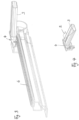
- the flexible sheet 2 is connected at its front end area in the extension direction to a dimensionally stable extension profile 3, which extends transversely across the width of the sheet 2. Based on the Fig. 1 the pull-out profile 3 is shown in two different positions.
- the pull-out profile 3 is coupled at its opposite ends to a guide member 4, which is guided longitudinally in the respective guide rail 6.
- the guide member 4 can be moved longitudinally in the respective guide rail 6 by means of a drive system.
- a longitudinal displacement of the pull-out profile 3 and thus of the guide members 4 can also be carried out manually by appropriately grasping the pull-out profile 3 and moving it along the guide rails 6.
- the respective stiffening band 7 is firmly connected to the guide member 4 in order to be able to be carried along by the guide member 4.
- the stiffening band 7 is designed as a flat band and is made of steel or a fiber-reinforced plastic strip.
- the stiffening band 7 is wound onto the winding shaft in the area of the cassette housing K together with the flexible sheet material and is pulled off from it.
- the stiffening band 7 protrudes beyond the flexible sheet material 2 at its front end area in the pull-out direction (see Fig. 5 to 7 ).
- the stiffening strip 7 is perforated in this area by a total of five holes, which represent passages 8 in the sense of the invention.
- the passages 8 are designed identically to one another and are arranged in a row at equal distances one behind the other.
- All passages 8 are circular and are preferably produced by punching.
- the front end area of the stiffening strip 7 is connected to a holding part 9 in the manner described in more detail below, which is then inserted into a receiving profile 17 of the guide member 4.
- the holding part 9 consists of an upper part 12 and a lower part 10, which are pivotally connected to one another via a film hinge 11.
- a pivot axis formed by the film hinge 11 extends parallel to a transverse extension of the pull-out profile 3.
- the lower part 10 is provided with a total of five pin-shaped profile sections 16, which protrude from the strip-shaped part 10 towards a common side. In the representation according to the Fig. 5 and 6 the pin-shaped profiling sections 16 protrude downwards.
- the upper portion 12 has five plug-in receptacles 15 complementary to the pin-shaped profiling sections 16, which have at least partially complementary plug-in cross-sections to the cross-sections of the pin-shaped profiling sections 16.
- the upper holding area 12 is first placed on the front end area of the stiffening band 7 until the plug-in receptacles 15 are aligned with the passages 8.
- the film hinge 11 is in this position ( Fig. 6 ) approximately at the level of a front edge of the stiffening band 7.
- the lower part 10 which still extends forwards like a tongue from the upper part 12, is cut out according to the arrow in Fig. 6 pivoted downwards, whereby the five pin-shaped profiling sections 16 pass through the passages 8 arranged one behind the other and into the plug receptacles 15.
- both the plug-in receptacles 15 and the pin-shaped profiling sections 16 extend in a radial plane to the pivot axis formed by the film hinge 11
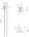
- the Fig. 10 It can be seen that all pin-shaped profile sections 16 and the associated plug-in receptacles 15 are curved in the shape of a circular arc. The circular arcs have different radii that correspond to the different distances of the individual pin-shaped profile sections 16 from the pivot axis formed by the film hinge 11.
- the circular arc curvature of the pin-shaped profile sections and the associated plug-in receptacles decreases in proportion to the distance that the individual profile sections and plug-in receptacles have from the pivot axis of the film hinge 11.
- the tongue that forms the film hinge 11 extends in the fully assembled state of the holding part 9 (see Fig. 7 and 10 ) around the front edge of the stiffening band 7.
- the pin-shaped profiling sections 16 are either held in the plug-in receptacles 15 in a purely force-fitting manner, or the profiling sections 16 and the complementary plug-in receptacles 15 are assigned additional locking profiles (not shown in detail) which secure the inserted end position of the profiling sections 16 and plug-in receptacles 15. Since the profiling sections 16 are also inserted through the passages 8 of the stiffening band 7 in a form-fitting manner, the holding part 9 is firmly connected to the stiffening band 7.
- the holding part 9 is additionally provided in the upper part 12 with a connecting section 13, which is designed as an essentially T-shaped profile.
- the guide member 4 has a complementary receiving profile 17, which is provided with a complementary T-shaped plug-in groove, which is open to the front in the extension direction.
- the receiving profile 17 is provided with a rear wall 18 that serves as an end stop.
- the holding part 9 is inserted with its connecting section 13 into the receiving profile 17 of the guide member 4, which is designed as a plug-in groove, parallel to the direction of extension of the stiffening band 7, until the connecting section 13 comes to rest on the front side of the rear wall 18.
- the connecting section 13 is also provided with an elastically flexible locking lug 14, which locks into a locking groove 19 of the guide member 4 in the inserted end position of the connecting section 13 (see in particular Fig. 10 ).
- the holding part 9 is thus inserted into the guide member 4 in a force-fitting manner and without play and is additionally secured in a form-fitting manner in the locking groove 19 of the guide member 4 via the locking lug 14.
- the form-fitting support in the opposite direction is provided by the rear wall 18.
- a longitudinal displacement of the guide member 4 therefore inevitably leads to a corresponding longitudinal displacement of the stiffening band 7 and consequently to a longitudinal displacement of the flexible sheet structure 2.
Landscapes
- Engineering & Computer Science (AREA)
- Mechanical Engineering (AREA)
- Vehicle Interior And Exterior Ornaments, Soundproofing, And Insulation (AREA)
- Vehicle Step Arrangements And Article Storage (AREA)
- Body Structure For Vehicles (AREA)
Description
- Die Erfindung betrifft eine Schutzvorrichtung für einen Fahrzeuginnenraum mit einem flexiblen Flächengebilde, das zwischen unterschiedlichen Funktionsstellungen im Fahrzeuginnenraum längsverlagerbar ist, und das an gegenüberliegenden Seitenrändern mit jeweils einem Versteifungsband versehen ist, die in fahrzeugfesten Führungsspuren längsverlagerbar geführt sind, sowie mit einem Auszugprofil, das quer zur Längsverlagerungsrichtung des Flächengebildes erstreckt und mit einem in Auszugrichtung vorderen Stirnendbereich des Flächengebildes verbunden ist, wobei das Auszugprofil mittels jeweils eines Führungsglieds in den fahrzeugfesten Führungsspuren geführt ist, und wobei jedes Versteifungsband stirnseitig an jeweils einem Führungsglied befestigt ist.
- Aus der
DE 10 2006 017 538 A1 ist eine Schutzvorrichtung in Form einer Rolloanordnung bekannt, bei der eine Rollobahn auf gegenüberliegenden Längsseiten mit jeweils einem Versteifungsband versehen ist. Das Versteifungsband dient zur Führung in jeweils einer fahrzeugfesten Führungsspur. Stirnseitig des Versteifungsbandes ist jeweils ein Mitnehmer vorgesehen, der fest mit dem Versteifungsband verbunden ist und mit einer Rollokupplung gekoppelt werden kann. Hierzu weist der Mitnehmer zwei Profilierungsabschnitte auf, die formschlüssig in zwei komplementäre Profilierungsaufnahmen der Rollokupplung eingreifen, um mit der Rollokupplung entlang der Führungsspur mitgenommen werden zu können. - Eine weitere Schutzvorrichtung in Form einer Beschattungsvorrichtung für einen Glasdachbereich eines Fahrzeuginnenraums eines Personenkraftwagens ist allgemein bekannt. Ein flexibles Flächengebilde in Form einer Beschattungsbahn ist auf einer Wickelwelle auf- und abwickelbar gehalten. Die Beschattungsbahn ist an ihren gegenüberliegenden Seitenrändern mit jeweils einem Versteifungsband versehen. Die Versteifungsbänder sind in dachfesten Führungsprofilierungen längsverschiebbar geführt. Jedes Versteifungsband ist zudem stirnseitig an einem Führungsglied befestigt, das in der jeweiligen dachfesten Führungsprofilierung längsverschiebbar geführt ist. An den Führungsgliedern ist ein Auszugprofil angelenkt, das sich quer zur Längsverlagerungsrichtung der Beschattungsbahn erstreckt und stirnendseitig an der Beschattungsbahn befestigt ist.
- Aufgabe der Erfindung ist es, eine Schutzvorrichtung der eingangs genannten Art zu schaffen, die eine verbesserte Verbindung der Versteifungsbänder mit den Führungsgliedern ermöglicht.
- Diese Aufgabe wird durch die Merkmale des Anspruchs 1 gelöst. Die wenigstens drei in Längsverlagerungsrichtung zueinander beabstandeten Profilierungsabschnitte ermöglichen eine verbesserte Verbindung zwischen dem jeweiligen Führungsglied und dem Stirnendbereich des Versteifungsbands. Ein unbeabsichtigtes Lösen des Versteifungsbands vom Führungsglied wird hierdurch vermieden. Die erfindungsgemäße Lösung ermöglicht eine gegenüber dem Stand der Technik verbesserte und verschleißarme Befestigung der Versteifungsbänder. Dadurch ist eine erhöhte Funktionssicherheit der Schutzvorrichtung gegeben. Die erfindungsgemäße Schutzvorrichtung kann zur Beschattung transparenter Flächen des Fahrzeuginnenraums wie insbesondere einem transparenten Glasdachbereich, einer Heckscheibe, von Seitenscheiben oder Ähnlichem vorgesehen sein. Alternativ kann die erfindungsgemäße Schutzvorrichtung zum Abtrennen und/oder Abdecken eines Laderaums des Fahrzeuginnenraums vorgesehen sein. Die in Längsverlagerungsrichtung hintereinander vorgesehenen Aufnahmen können als zumindest teilweise geschlossene Vertiefungen Seiten oder als zu gegenüberliegenden offene Durchtritte gestaltet sein. Falls sie als Vertiefungen gestaltet sind, können diese in Form von Einprägungen oder Ähnlichem ausgebildet sein. Die Profilierungsabschnitte sind vorzugsweise bezüglich ihres Querschnitts komplementär zu entsprechenden freien Querschnitten der Aufnahmen ausgeführt, um ein zumindest weitgehend spielfreies Einstecken der Profilierungsabschnitte in die Aufnahmen zu ermöglichen.
- Erfindungsgemäß sind die Profilierungsabschnitte an einem Halteteil angeordnet, das mit dem Führungsglied verbunden ist. Die Profilierungsabschnitte sind vorzugsweise einstückig an dem Halteteil angeformt. Das Halteteil ist vorteilhaft aus Kunststoff hergestellt. Die Profilierungsabschnitte ragen zu einer Seite von dem Halteteil ab. Beim Einsatz der Ausgestaltung für eine Schutzvorrichtung zur Beschattung eines Glasdachbereichs ist das Halteteil vorzugsweise jeweils im Bereich einer Unterseite des jeweiligen Versteifungsbands positioniert und die Profilierungsabschnitte ragen durch die Aufnahmen des Versteifungsbands hindurch nach oben.
- Erfindungsgemäß sind die Profilierungsabschnitte stiftförmig ausgeführt.
- Erfindungsgemäß sind die Aufnahmen des Versteifungsbands als Durchtritte gestaltet, die zu den stiftförmigen Profilierungsabschnitten komplementäre Durchtrittsquerschnitte aufweisen.
- In weiterer Ausgestaltung der Erfindung weisen die stiftförmigen Profilierungsabschnitte und die Durchtritte jeweils kreisförmige Querschnitte auf. Die kreisförmigen Querschnitte sind einfach herstellbar und ermöglichen eine zumindest weitgehend spielfreie Kontaktierung zwischen Profilierungsabschnitten und Durchtritten. In vorteilhafter Weise sind die stiftförmigen Profilierungsabschnitte in Längsverlagerungsrichtung in einer Reihe hintereinander angeordnet. Die Profilierungsabschnitte erstrecken sich vorteilhaft in einer gemeinsamen Ebene, die orthogonal und längs einer Oberfläche des jeweiligen Versteifungsbands verläuft.
- In weiterer Ausgestaltung der Erfindung weist das Halteteil einen Verbindungsabschnitt zur Sicherung des Halteteils an dem Führungsglied auf. Das Halteteil stellt ein vom jeweiligen Führungsglied getrenntes Bauteil dar. Vorzugsweise werden das Halteteil und der jeweilige Stirnendbereich des Versteifungsbands in einem Vormontageschritt miteinander verbunden, bevor anschließend das Halteteil mit dem Führungsglied verbunden wird. Der Verbindungsabschnitt ist vorzugsweise derart ausgeführt, dass ein werkzeugloses Verbinden des Halteteils mit dem Führungsglied ermöglicht ist.
- In weiterer Ausgestaltung der Erfindung ist das Führungsglied mit einer Aufnahmeprofilierung zur Befestigung des Verbindungsabschnitts an dem Führungsglied versehen. In vorteilhafter Ausgestaltung ist die Aufnahmeprofilierung als Stecknut gestaltet, und der Verbindungsabschnitt weist eine zu der Stecknut komplementäre Steckkontur auf. Vorteilhaft ist die Stecknut zu einer in Längsverlagerungsrichtung gerichteten Stirnseite des Führungsglieds hin offen. Dadurch kann der Verbindungsabschnitt des Halteteils über die offene Stirnseite in die Stecknut eingesteckt werden. Vorteilhaft erstreckt sich demzufolge die Stecknut in Längsverlagerungsrichtung. Für eine Montage der Schutzvorrichtung wird zunächst das Halteteil mit den Durchtritten des Versteifungsbands formschlüssig verbunden und anschließend wird das Halteteil mit seinem Verbindungsabschnitt in die Aufnahmeprofilierung des Führungsglieds eingesteckt.
- In weiterer Ausgestaltung der Erfindung ist wenigstens ein elastisch nachgiebiges Rastelement an dem Verbindungsabschnitt oder der Aufnahmeprofilierung vorgesehen, das den Verbindungsabschnitt in eingesteckter Endstellung in der Stecknut formschlüssig sichert. Vorzugsweise weist die Stecknut in Einsteckrichtung einen Endanschlag auf, an dem der Verbindungsabschnitt des Halteteils beim Einstecken in die Stecknut anschlägt. Das elastisch nachgiebige Rastelement ist derart gestaltet, dass es in seine Rastposition einrastet, sobald der Verbindungsabschnitt seine eingesteckte Endstellung in der Stecknut erreicht hat. Die Stecknut weist hierzu vorzugsweise eine zu dem Rastelement komplementäre Rastprofilierung auf, in die das elastisch nachgiebige Rastelement in der Endstellung des Verbindungsabschnitts einrastet.
- Erfindungsgemäß weist das Halteteil zwei Teilbereiche auf, die in montiertem Zustand das Versteifungsband beidseitig flankieren. Beide Teilbereiche sind vorzugsweise aus Kunststoff hergestellt. Das Versteifungsband kann als flaches Stahlband oder als faserverstärktes Kunststoffband, insbesondere als Teflonband, ausgeführt sein.
- Erfindungsgemäß sind die Teilbereiche mittels eines Scharniers miteinander gelenkig verbunden. Das Scharnier definiert eine Schwenkachse, die quer zur Längsverlagerungsrichtung des Versteifungsbands, aber in oder parallel zu einer Ebene des Versteifungsbands, verläuft. Vorzugsweise ist das Scharnier als Filmscharnier gestaltet.
- In weiterer Ausgestaltung der Erfindung sind die stiftförmigen Profilierungsabschnitte und die Steckaufnahmen in einer gemeinsamen Ebene gleichsinnig gekrümmt. Die gemeinsame Ebene wird vorzugsweise durch eine Radialebene der Schwenkachse des Scharniers gebildet.
- In weiterer Ausgestaltung der Erfindung sind die Profilierungsabschnitte und die Steckaufnahmen kreisbogenförmig gekrümmt entsprechend von unterschiedlichen Kreisbögen, die in der gemeinsamen Ebene einen gemeinsamen Mittelpunkt, nämlich eine Schwenkachse des Scharniers, aufweisen, und deren Radien den Abständen der jeweiligen Profilierungsabschnitte bzw. Steckaufnahmen zu dem Mittelpunkt entsprechen. Dadurch ist bei einem Verschwenken der beiden Teilbereiche des Halteteils gegeneinander gewährleistet, dass die Profilierungsabschnitte exakt bei weitgehend gleichbleibender Belastung in die Steckaufnahmen eintauchen. In vorteilhafter Weise können die Profilierungsabschnitte und die komplementären Steckaufnahmen endseitig mit Rastprofilierungen versehen sein, um ein Einrasten und demzufolge ein Sichern der Profilierungsabschnitte in den Steckaufnahmen in der zusammengefügten Endstellung der beiden Teilbereiche des Halteteils zu ermöglichen.
- Weitere Vorteile und Merkmale der Erfindung ergeben sich aus den Ansprüchen sowie aus der nachfolgenden Beschreibung eines bevorzugten Ausführungsbeispiels der Erfindung, das anhand der Zeichnungen dargestellt ist.
- Fig. 1
- zeigt einen Ausschnitt einer Ausführungsform einer erfindungsgemäßen Schutzvorrichtung in Form eines Beschattungssystems für einen Glasdachbereich eines Personenkraftwagens,
- Fig. 2
- einen Ausschnitt II der Darstellung nach
Fig. 1 , jedoch vergrößert, - Fig. 3
- in perspektivischer Darstellung einen Teilbereich der Schutzvorrichtung nach den
Fig. 1 und 2 , - Fig. 4
- in vergrößerter Darstellung einen Teilbereich der Schutzvorrichtung nach
Fig. 3 , - Fig. 5
- einen ersten Montageschritt zur Verbindung eines Führungsglieds mit einem flexiblen Flächengebilde gemäß
Fig. 4 , - Fig. 6
- einen weiteren Montageschritt anschließend an
Fig. 5 , - Fig. 7
- einen weiteren Montageschritt anschließend an
Fig. 6 , - Fig. 8
- eine Längsschnittdarstellung der Schutzvorrichtung gemäß
Fig. 3 , - Fig. 9
- schematisch eine Frontansicht eines Führungsglieds der Schutzvorrichtung nach
Fig. 8 und - Fig. 10
- einen Schnitt entlang der Schnittlinie X-X der Darstellung nach
Fig. 9 . - Eine Schutzvorrichtung 1 nach den
Fig. 1 bis 10 ist als Beschattungsvorrichtung für einen Glasdachbereich eines Personenkraftwagens vorgesehen. Die Beschattungsvorrichtung ist im Fahrzeuginnenraum unterhalb des Glasdachbereichs vorgesehen und weist ein flexibles Flächengebilde 2 auf, das auch als Beschattungsbahn bezeichnet wird. Das flexible Flächengebilde 2 ist auf einer Wickelwelle auf- und abwickelbar gehalten, die in einem dachfest montierten Kassettengehäuse K (Fig. 8 ) drehbar gelagert ist. Das flexible Flächengebilde 2 ist an seinen gegenüberliegenden Seitenrändern mit jeweils einem Versteifungsband 7 versehen, das in jeweils einer dachfesten und damit fahrzeugfesten Führungsspur in Form einer Führungsschiene 6 längsverschiebbar geführt ist. Anhand derFig. 1 bis 10 ist lediglich eine der dachfesten Führungsschienen 6 gezeigt. Eine gegenüberliegende Seite der Schutzvorrichtung 1 einschließlich der Führungsschiene 6 ist relativ zu einer vertikalen Mittellängsachse spiegelsymmetrisch, im Übrigen jedoch identisch gestaltet. Zur Vermeidung von Wiederholungen wird nachfolgend lediglich die eine Seite anhand der Zeichnungen gemäß denFig. 1 bis 10 beschrieben. Für die gegenüberliegende Seite gilt das Gesagte in gleicher Weise. - Das flexible Flächengebilde 2 ist längs der Führungsschienen 6 verlagerbar zwischen einer auf die Wickelwelle aufgewickelten Ruhestellung, d.h. einer ersten Funktionsstellung, und einer bis zu einem Endbereich der Führungsschienen 6 ausgezogenen zweiten Funktionsstellung. Die beiden Versteifungsbänder 7, die den gegenüberliegenden Seitenrändern des flexiblen Flächengebildes 2 zugeordnet und in den fahrzeugfesten Führungsschienen 6 geführt sind, dienen dazu, auf das flexible Flächengebilde 2 eine permanente Querspannung quer zur Längsverlagerungsrichtung auszuüben. Dadurch wird ein Durchhängen des flexiblen Flächengebildes 2 vermieden. Das flexible Flächengebilde 2 ist an seinem in Auszugrichtung vorderen Stirnendbereich mit einem formstabilen Auszugprofil 3 verbunden, das sich in Querrichtung über die Breite des Flächengebildes 2 erstreckt. Anhand der
Fig. 1 ist das Auszugprofil 3 in zwei unterschiedlichen Stellungen dargestellt. Das Auszugprofil 3 ist an seinen gegenüberliegenden Stirnenden mit jeweils einem Führungsglied 4 gekoppelt, das in der jeweiligen Führungsschiene 6 längsverschiebbar geführt ist. Beim dargestellten Ausführungsbeispiel ist das Führungsglied 4 mittels eines Antriebssystems in der jeweiligen Führungsschiene 6 längsverlagerbar. In gleicher Weise kann eine Längsverlagerung des Auszugprofils 3 und damit der Führungsglieder 4 jedoch auch manuell durch entsprechendes Ergreifen des Auszugprofils 3 und Verschieben längs der Führungsschienen 6 erfolgen. - Das jeweilige Versteifungsband 7 ist mit dem Führungsglied 4 fest verbunden, um von dem Führungsglied 4 mitgenommen werden zu können. Das Versteifungsband 7 ist als Flachband ausgeführt und aus Stahl oder einem faserverstärkten Kunststoffstreifen hergestellt. Das Versteifungsband 7 wird im Bereich das Kassettengehäuses K gemeinsam mit dem flexiblen Flächengebilde auf die Wickelwelle aufgewickelt und von dieser abgezogen. Das Versteifungsband 7 ragt an seinem in Auszugrichtung vorderen Stirnendbereich über das flexible Flächengebilde 2 hinaus (siehe
Fig. 5 bis 7 ). Das Versteifungsband 7 ist in diesem Bereich gelocht durch insgesamt fünf Löcher, die Durchtritte 8 im Sinne der Erfindung darstellen. Die Durchtritte 8 sind identisch zueinander gestaltet und in einer Reihe in gleichmäßigen Abständen hintereinander angeordnet. Alle Durchtritte 8 sind kreisförmig ausgeführt und vorzugsweise durch Stanzen hergestellt. Der vordere Stirnendbereich des Versteifungsbands 7 wird in nachfolgend näher beschriebener Weise mit einem Halteteil 9 verbunden, das anschließend in eine Aufnahmeprofilierung 17 des Führungsglieds 4 eingefügt wird. Das Halteteil 9 besteht aus einem oberen Teilbereich 12 und einem unteren Teilbereich 10, die über ein Filmscharnier 11 schwenkbeweglich miteinander verbunden sind. Eine durch das Filmscharnier 11 gebildete Schwenkachse erstreckt sich parallel zu einer Quererstreckung des Auszugprofils 3. Der untere Teilbereich 10 ist mit insgesamt fünf stiftförmigen Profilierungsabschnitten 16 versehen, die zu einer gemeinsamen Seite hin von dem leistenförmigen Teilbereich 10 aus abragen. In der Darstellung gemäß denFig. 5 und 6 ragen die stiftförmigen Profilierungsabschnitte 16 nach unten ab. - Der obere Teilbereich 12 weist komplementär zu den stiftförmigen Profilierungsabschnitten 16 fünf Steckaufnahmen 15 auf, die zumindest teilweise komplementäre Steckquerschnitte zu den Querschnitten der stiftförmigen Profilierungsabschnitte 16 aufweisen.
- Wie anhand der
Fig. 5 bis 7 erkennbar ist, wird zur Verbindung des Halteteils 9 mit dem Versteifungsband 7 zunächst der obere Haltebereich 12 auf den vorderen Stirnendbereich des Versteifungsbands 7 aufgesetzt, bis die Steckaufnahmen 15 mit den Durchtritten 8 fluchten. Das Filmscharnier 11 befindet sich in dieser Position (Fig. 6 ) etwa auf Höhe einer vorderen Stirnkante des Versteifungsbands 7. Anschließend wird der untere Teilbereich 10, der sich noch zungenartig von dem oberen Teilbereich 12 aus nach vorne erstreckt, gemäß der Pfeildarstellung inFig. 6 nach unten verschwenkt, wodurch nacheinander die fünf stiftförmigen Profilierungsabschnitte 16 durch die hintereinander angeordneten Durchtritte 8 hindurchtauchen und in die Steckaufnahmen 15 hineintauchen. - Anhand der
Fig. 10 ist erkennbar, dass sowohl die Steckaufnahmen 15 als auch die stiftförmigen Profilierungsabschnitte 16 in einer Radialebene zur Schwenkachse, die durch das Filmscharnier 11 gebildet ist, erstreckt sind. Zudem ist anhand derFig. 10 erkennbar, dass alle stiftförmigen Profilierungsabschnitte 16 und die zugeordneten Steckaufnahmen 15 kreisbogenförmig gekrümmt sind. Dabei weisen die Kreisbögen unterschiedliche Radien auf, die den unterschiedlichen Abständen der einzelnen stiftförmigen Profilierungsabschnitte 16 zu der durch das Filmscharnier 11 gebildeten Schwenkachse entsprechen. Demzufolge nimmt die kreisbogenförmige Krümmung der stiftförmigen Profilierungsabschnitte und der zugeordneten Steckaufnahmen im Verhältnis zu dem Abstand ab, den die einzelnen Profilierungsabschnitte und Steckaufnahmen zur Schwenkachse des Filmscharniers 11 haben. Die Zunge, die das Filmscharnier 11 bildet, erstreckt sich in fertig montiertem Zustand des Halteteils 9 (sieheFig. 7 und10 ) um die vordere Stirnkante des Versteifungsbands 7 herum. Die stiftförmigen Profilierungsabschnitte 16 sind entweder rein kraftschlüssig in den Steckaufnahmen 15 gehalten, oder den Profilierungsabschnitten 16 und den komplementären Steckaufnahmen 15 sind zusätzliche, nicht näher dargestellte Rastprofilierungen zugeordnet, die die eingesteckte Endstellung von Profilierungsabschnitten 16 und Steckaufnahmen 15 sichern. Da zudem die Profilierungsabschnitte 16 formschlüssig durch die Durchtritte 8 des Versteifungsbands 7 hindurchgesteckt sind, ist das Halteteil 9 fest mit dem Versteifungsband 7 verbunden. - Das Halteteil 9 ist im oberen Teilbereich 12 zusätzlich mit einem Verbindungsabschnitt 13 versehen, der als im Wesentlichen T-förmiges Profil gestaltet ist. Das Führungsglied 4 weist komplementär hierzu eine Aufnahmeprofilierung 17 auf, die mit einer komplementär T-förmigen Stecknut versehen ist, die in Auszugrichtung nach vorne offen ist. Rückseitig ist die Aufnahmeprofilierung 17 mit einer als Endanschlag dienenden Rückwand 18 versehen. Das Halteteil 9 wird mit seinem Verbindungsabschnitt 13 in die als Stecknut gestaltete Aufnahmeprofilierung 17 des Führungsglieds 4 parallel zur Erstreckungsrichtung des Versteifungsbands 7 eingeschoben, bis der Verbindungsabschnitt 13 stirnseitig an der Rückwand 18 zur Anlage kommt. Der Verbindungsabschnitt 13 ist zudem mit einer elastisch nachgiebigen Rastnase 14 versehen, die in der eingesteckten Endstellung des Verbindungsabschnitts 13 in eine Rastnut 19 des Führungsglieds 4 einrastet (siehe insbesondere
Fig. 10 ). Damit ist das Halteteil 9 zum einen kraftschlüssig und spielfrei in das Führungsglied 4 eingesteckt und zusätzlich über die Rastnase 14 formschlüssig in der Rastnut 19 des Führungsglieds 4 gesichert. Die formschlüssige Stützung in entgegengesetzter Richtung wird durch die Rückwand 18 übernommen. - Eine Längsverlagerung des Führungsglieds 4 führt demzufolge zwangsläufig zu einer entsprechenden Längsverlagerung des Versteifungsbands 7 und demzufolge zu einer Längsverlagerung des flexiblen Flächengebildes 2.
Claims (10)
- Schutzvorrichtung (1) für einen Fahrzeuginnenraum mit einem flexiblen Flächengebilde (2), das zwischen unterschiedlichen Funktionsstellungen im Fahrzeuginnenraum längsverlagerbar ist, und das an gegenüberliegenden Seitenrändern mit jeweils einem Versteifungsband (7) versehen ist, die in fahrzeugfesten Führungsspuren längsverlagerbar geführt sind, gekennzeichnet durch einen Auszugprofil (3), das quer zur Längsverlagerungsrichtung des Flächengebildes (2) erstreckt und mit einem in Auszugrichtung vorderen Stirnendbereich des Flächengebildes (2) verbunden ist, wobei das Auszugprofil (3) mittels jeweils eines Führungsglieds (4) in den fahrzeugfesten Führungsspuren geführt ist, und wobei jedes Versteifungsband (7) stirnseitig an dem jeweils einen Führungsglied (4) befestigt ist, wobei jedes Versteifungsband (7) wenigstens drei in Längsverlagerungsrichtung hintereinander vorgesehene Aufnahmen (8) aufweist, und dass dem Führungsglied (4) wenigstens drei in Längsverlagerungsrichtung zueinander beabstandete Profilierungsabschnitte (16) zugeordnet sind, die quer zur Längsverlagerungsrichtung formschlüssig in die Aufnahmen (8) hineinragen, dass die Profilierungsabschnitte stiftförmig ausgeführt und an einem Halteteil (9) angeordnet sind, das mit dem Führungsglied (4) verbunden ist, dass das Halteteil (9) zwei Teilbereiche (10, 12) aufweist, die in montiertem Zustand das Versteifungsband (7) beidseitig flankieren und
dass ein Teilbereich (10) mit den stiftförmigen Profilierungsabschnitten (16) und der gegenüberliegende Teilbereich (12) mit Steckaufnahmen versehen ist, die kraft- und/oder formschlüssig auf die stiftförmigen Profilierungsabschnitte abgestimmt sind, dass die Aufnahmen des Versteifungsbands als Durchtritte (8) gestaltet sind, die zu den stiftförmigen Profilierungsabschnitten (16) komplementäre Durchtrittsquerschnitte aufweisen und dass die Teilbereiche (10, 12) mittels eines Scharniers miteinander gelenkig verbunden sind, wobei das Scharnier eine Schwenkachse definiert, die quer zu einer Längsverlagerungsrichtung des Versteifungsbandes 7, aber in oder parallel zu einer Ebene des Versteifungsbandes 7, verläuft. - Schutzvorrichtung nach Anspruch 1, dadurch gekennzeichnet, dass die stiftförmigen Profilierungsabschnitte (16) und die Durchtritte (8) jeweils kreisförmige Querschnitte aufweisen.
- Schutzvorrichtung nach einem der vorhergehenden Ansprüche, dadurch gekennzeichnet, dass die stiftförmigen Profilierungsabschnitte (16) in Längsverlagerungsrichtung in einer Reihe hintereinander angeordnet sind.
- Schutzvorrichtung nach einem der vorhergehenden Ansprüche, dadurch gekennzeichnet, dass das Halteteil (9) einen Verbindungsabschnitt (13) zur Sicherung des Halteteils (9) an dem Führungsglied (4) aufweist.
- Schutzvorrichtung nach Anspruch 4, dadurch gekennzeichnet, dass das Führungsglied (4) mit einer Aufnahmeprofilierung (17) zur Befestigung des Verbindungsabschnitts (13) an dem Führungsglied (4) versehen ist.
- Schutzvorrichtung nach Anspruch 5, dadurch gekennzeichnet, dass die Aufnahmeprofilierung als Stecknut (17) gestaltet ist, und dass der Verbindungsabschnitt (13) eine zu der Stecknut (17) komplementäre Steckkontur aufweist.
- Schutzvorrichtung nach einem der Ansprüche 4 bis 6, dadurch gekennzeichnet, dass wenigstens ein elastisch nachgiebiges Rastelement (14) an dem Verbindungsabschnitt (13) oder der Aufnahmeprofilierung vorgesehen ist, das den Verbindungsabschnitt (13) in eingesteckter Endstellung in der Aufnahmeprofilierung formschlüssig sichert.
- Schutzvorrichtung nach Anspruch 1, dadurch gekennzeichnet, dass das Scharnier als Filmscharnier (11) gestaltet ist.
- Schutzvorrichtung nach Anspruch 1, dadurch gekennzeichnet, dass die stiftförmigen Profilierungsabschnitte (16) und die Steckaufnahmen (15) in einer gemeinsamen Ebene gleichsinnig gekrümmt sind.
- Schutzvorrichtung nach Anspruch 9, dadurch gekennzeichnet, dass die Profilierungsabschnitte (16) und die Steckaufnahmen (15) kreisbogenförmig gekrümmt sind entsprechend von unterschiedlichen Kreisbögen, die in der gemeinsamen Ebene einen gemeinsamen Mittelpunkt, nämlich eine Schwenkachse des Scharniers, aufweisen und deren Radien den Abständen der jeweiligen Profilierungsabschnitte bzw. Steckaufnahmen zu dem Mittelpunkt entsprechen.
Applications Claiming Priority (1)
| Application Number | Priority Date | Filing Date | Title |
|---|---|---|---|
| DE102017211784.2A DE102017211784A1 (de) | 2017-07-10 | 2017-07-10 | Schutzvorrichtung für einen Fahrzeuginnenraum |
Publications (3)
| Publication Number | Publication Date |
|---|---|
| EP3427984A1 EP3427984A1 (de) | 2019-01-16 |
| EP3427984B1 EP3427984B1 (de) | 2021-08-04 |
| EP3427984B2 true EP3427984B2 (de) | 2025-01-29 |
Family
ID=62715832
Family Applications (1)
| Application Number | Title | Priority Date | Filing Date |
|---|---|---|---|
| EP18177327.6A Active EP3427984B2 (de) | 2017-07-10 | 2018-06-12 | Schutzvorrichtung für einen fahrzeuginnenraum |
Country Status (4)
| Country | Link |
|---|---|
| US (1) | US11034220B2 (de) |
| EP (1) | EP3427984B2 (de) |
| CN (1) | CN109228833A (de) |
| DE (1) | DE102017211784A1 (de) |
Families Citing this family (5)
| Publication number | Priority date | Publication date | Assignee | Title |
|---|---|---|---|---|
| JP7010123B2 (ja) * | 2018-04-12 | 2022-01-26 | 株式会社アイシン | シェード装置 |
| DE102019114302A1 (de) * | 2019-05-28 | 2020-12-03 | Webasto SE | Rolloanordnung für ein Fahrzeug und Verfahren zum Herstellen einer Rolloanordnung |
| FR3096631B1 (fr) | 2019-05-31 | 2021-11-12 | Inteva Products France Sas | Cache-bagages motorisé pour vehicule |
| DE202019104691U1 (de) * | 2019-08-27 | 2020-12-01 | Inalfa Roof Systems Group B.V. | Führungsbaugruppe für ein Rollosystem |
| DE102021108564A1 (de) | 2021-04-07 | 2022-10-13 | Dr. Ing. H.C. F. Porsche Aktiengesellschaft | Bauteil eines Kraftfahrzeugs |
Citations (1)
| Publication number | Priority date | Publication date | Assignee | Title |
|---|---|---|---|---|
| KR101564012B1 (ko) † | 2013-12-23 | 2015-10-28 | (주)베바스토동희 홀딩스 | 롤러 블라인드의 사이드 고정장치 |
Family Cites Families (16)
| Publication number | Priority date | Publication date | Assignee | Title |
|---|---|---|---|---|
| GB9019696D0 (en) * | 1990-09-08 | 1990-10-24 | Britax Weathershields | Blind for vehicle opening roof |
| CA2288382C (en) * | 1998-11-03 | 2008-12-30 | Hunter Douglas Industries B.V. | Holder for a depending architectural covering |
| DE10113621C1 (de) * | 2001-03-20 | 2002-10-10 | Butz Peter Verwaltung | Laderaumabdeckung für Kraftwagen, wie für Kombinations-Personenkraftwagen od. dgl. |
| FR2846284B1 (fr) * | 2002-10-28 | 2006-02-10 | Webasto Systemes Carrosserie | Dispositif de toit ouvrant avec rideau occulteur |
| US6945304B1 (en) * | 2003-04-03 | 2005-09-20 | Tmi Incorporated | Flexible-strip hanger for a strip door system and method of making |
| DE102005024657C5 (de) * | 2004-11-19 | 2016-04-21 | Webasto Ag | Rolloanordnung für ein Fahrzeug |
| EP1960220B1 (de) | 2005-12-12 | 2010-01-20 | Webasto AG | Rollokupplung für ein fahrzeugsonnendachrollo, sowie rolloband, sowie fahrzeugsonnendachrollo |
| DE102006017538B4 (de) | 2006-04-13 | 2010-08-12 | Webasto Ag | Rolloanordnung für ein Fahrzeug |
| DE102006054881A1 (de) * | 2006-11-20 | 2008-05-21 | Bos Gmbh & Co. Kg | Dachfensterrollo |
| US20090195034A1 (en) * | 2008-02-01 | 2009-08-06 | Macauto Industrial Co., Ltd. | Sunshade assembly |
| JP5391165B2 (ja) * | 2009-09-24 | 2014-01-15 | 八千代工業株式会社 | 車両のロールシェード装置 |
| DE102012219523B4 (de) * | 2012-10-25 | 2016-02-18 | Bos Gmbh & Co. Kg | Rollovorrichtung für ein Kraftfahrzeug |
| DE102014209144A1 (de) * | 2013-06-28 | 2014-12-31 | Bos Gmbh & Co. Kg | Schutzvorrichtung für einen Fahrzeuginnenraum |
| DE102014005475A1 (de) | 2014-04-15 | 2015-10-15 | Webasto SE | Rollovorrichtung an einem Fahrzeugdach |
| DE102014005476A1 (de) * | 2014-04-15 | 2015-10-15 | Webasto SE | Rollovorrichtung an einem Fahrzeugdach |
| EP3064386B1 (de) | 2015-03-04 | 2020-02-12 | Inalfa Roof Systems Group B.V. | Sonnenschirmanordnung und damit ausgestattete offene Dachkonstruktion |
-
2017
- 2017-07-10 DE DE102017211784.2A patent/DE102017211784A1/de not_active Ceased
-
2018
- 2018-06-12 EP EP18177327.6A patent/EP3427984B2/de active Active
- 2018-06-27 US US16/019,926 patent/US11034220B2/en active Active
- 2018-07-10 CN CN201810752493.2A patent/CN109228833A/zh active Pending
Patent Citations (1)
| Publication number | Priority date | Publication date | Assignee | Title |
|---|---|---|---|---|
| KR101564012B1 (ko) † | 2013-12-23 | 2015-10-28 | (주)베바스토동희 홀딩스 | 롤러 블라인드의 사이드 고정장치 |
Also Published As
| Publication number | Publication date |
|---|---|
| DE102017211784A1 (de) | 2019-01-10 |
| EP3427984B1 (de) | 2021-08-04 |
| US11034220B2 (en) | 2021-06-15 |
| CN109228833A (zh) | 2019-01-18 |
| EP3427984A1 (de) | 2019-01-16 |
| US20190009656A1 (en) | 2019-01-10 |
Similar Documents
| Publication | Publication Date | Title |
|---|---|---|
| EP3427984B2 (de) | Schutzvorrichtung für einen fahrzeuginnenraum | |
| EP1347896B1 (de) | Wischvorrichtung, insbesondere für scheiben von kraftfahrzeugen | |
| DE102008000708A1 (de) | Wischblatt | |
| DE2724414C3 (de) | Einrichtung zum Überführen des Sonnenblendenkörpers einer Sonnenblende für Fahrzeuge von einer Nichtgebrauchslage in eine Gebrauchslage | |
| EP2979906B1 (de) | Beschattungsvorrichtung für ein transparentes flächenteil eines kraftfahrzeugs | |
| EP0592855B1 (de) | Sonnenblende für Fahrzeuge | |
| DE102015002848A1 (de) | Jalousie insbesondere für ein Ablagefach in einem Kraftwagen | |
| EP3331716B1 (de) | Windabweiser mit befestigungssystem für aufspannbares abweiserelement | |
| DE10147621B4 (de) | Befestigungsanordnung für einen seitlichen Endbereich einer Front- oder Heckschürze eines Fahrzeugs | |
| DE60016116T2 (de) | Lüftungsgitter, insbesondere für Kraftfahrzeuge | |
| WO2016096251A1 (de) | Schutzvorrichtung für einen fahrzeuginnenraum | |
| DE102020114966A1 (de) | Schiebeabdeckung für eine Dachöffnung eines Nutzfahrzeug-Laderaums | |
| DE19511066C1 (de) | Schiebehimmel für Kraftfahrzeugdächer | |
| DE102015003719B4 (de) | Jalousie insbesondere für ein Ablagefach in einem Kraftwagen | |
| EP2487058A1 (de) | Deckel für ein Schiebedachsystem | |
| DE102021206022A1 (de) | Beschattungsvorrichtung für einen Fahrzeuginnenraum eines Kraftfahrzeugs | |
| DE3718840C1 (en) | Window lifter for motor vehicles | |
| EP3199733B1 (de) | Vorrichtung zum verschliessen von gebäudeöffnungen | |
| DE102021208515B4 (de) | Beschattungsvorrichtung für einen transparenten Flächenabschnitt eines Kraftfahrzeugs | |
| DE102019200266B4 (de) | Antriebssystem für ein Spoilerdachmodul eines Kraftfahrzeugs | |
| DE19611499B4 (de) | Lamellenanordnung für, insbesondere lichtdurchlässige, Kraftfahrzeug-Sonnendächer | |
| DE202007008049U1 (de) | Führungsbaugruppe eines Kraftfahrzeugfensterhebers | |
| DE10309185B4 (de) | Schiebefenster für ein Fahrzeug | |
| DE102007025506A1 (de) | Lamellenwalze | |
| DE102022125686A1 (de) | Fächersystem |
Legal Events
| Date | Code | Title | Description |
|---|---|---|---|
| PUAI | Public reference made under article 153(3) epc to a published international application that has entered the european phase |
Free format text: ORIGINAL CODE: 0009012 |
|
| STAA | Information on the status of an ep patent application or granted ep patent |
Free format text: STATUS: THE APPLICATION HAS BEEN PUBLISHED |
|
| AK | Designated contracting states |
Kind code of ref document: A1 Designated state(s): AL AT BE BG CH CY CZ DE DK EE ES FI FR GB GR HR HU IE IS IT LI LT LU LV MC MK MT NL NO PL PT RO RS SE SI SK SM TR |
|
| AX | Request for extension of the european patent |
Extension state: BA ME |
|
| STAA | Information on the status of an ep patent application or granted ep patent |
Free format text: STATUS: REQUEST FOR EXAMINATION WAS MADE |
|
| 17P | Request for examination filed |
Effective date: 20190715 |
|
| RBV | Designated contracting states (corrected) |
Designated state(s): AL AT BE BG CH CY CZ DE DK EE ES FI FR GB GR HR HU IE IS IT LI LT LU LV MC MK MT NL NO PL PT RO RS SE SI SK SM TR |
|
| STAA | Information on the status of an ep patent application or granted ep patent |
Free format text: STATUS: EXAMINATION IS IN PROGRESS |
|
| 17Q | First examination report despatched |
Effective date: 20200529 |
|
| GRAP | Despatch of communication of intention to grant a patent |
Free format text: ORIGINAL CODE: EPIDOSNIGR1 |
|
| STAA | Information on the status of an ep patent application or granted ep patent |
Free format text: STATUS: GRANT OF PATENT IS INTENDED |
|
| INTG | Intention to grant announced |
Effective date: 20210301 |
|
| GRAS | Grant fee paid |
Free format text: ORIGINAL CODE: EPIDOSNIGR3 |
|
| GRAA | (expected) grant |
Free format text: ORIGINAL CODE: 0009210 |
|
| STAA | Information on the status of an ep patent application or granted ep patent |
Free format text: STATUS: THE PATENT HAS BEEN GRANTED |
|
| AK | Designated contracting states |
Kind code of ref document: B1 Designated state(s): AL AT BE BG CH CY CZ DE DK EE ES FI FR GB GR HR HU IE IS IT LI LT LU LV MC MK MT NL NO PL PT RO RS SE SI SK SM TR |
|
| REG | Reference to a national code |
Ref country code: GB Ref legal event code: FG4D Free format text: NOT ENGLISH |
|
| REG | Reference to a national code |
Ref country code: AT Ref legal event code: REF Ref document number: 1416635 Country of ref document: AT Kind code of ref document: T Effective date: 20210815 |
|
| REG | Reference to a national code |
Ref country code: CH Ref legal event code: EP |
|
| REG | Reference to a national code |
Ref country code: DE Ref legal event code: R096 Ref document number: 502018006398 Country of ref document: DE |
|
| REG | Reference to a national code |
Ref country code: IE Ref legal event code: FG4D Free format text: LANGUAGE OF EP DOCUMENT: GERMAN |
|
| REG | Reference to a national code |
Ref country code: LT Ref legal event code: MG9D |
|
| REG | Reference to a national code |
Ref country code: NL Ref legal event code: MP Effective date: 20210804 |
|
| PG25 | Lapsed in a contracting state [announced via postgrant information from national office to epo] |
Ref country code: NO Free format text: LAPSE BECAUSE OF FAILURE TO SUBMIT A TRANSLATION OF THE DESCRIPTION OR TO PAY THE FEE WITHIN THE PRESCRIBED TIME-LIMIT Effective date: 20211104 Ref country code: PT Free format text: LAPSE BECAUSE OF FAILURE TO SUBMIT A TRANSLATION OF THE DESCRIPTION OR TO PAY THE FEE WITHIN THE PRESCRIBED TIME-LIMIT Effective date: 20211206 Ref country code: BG Free format text: LAPSE BECAUSE OF FAILURE TO SUBMIT A TRANSLATION OF THE DESCRIPTION OR TO PAY THE FEE WITHIN THE PRESCRIBED TIME-LIMIT Effective date: 20211104 Ref country code: LT Free format text: LAPSE BECAUSE OF FAILURE TO SUBMIT A TRANSLATION OF THE DESCRIPTION OR TO PAY THE FEE WITHIN THE PRESCRIBED TIME-LIMIT Effective date: 20210804 Ref country code: RS Free format text: LAPSE BECAUSE OF FAILURE TO SUBMIT A TRANSLATION OF THE DESCRIPTION OR TO PAY THE FEE WITHIN THE PRESCRIBED TIME-LIMIT Effective date: 20210804 Ref country code: SE Free format text: LAPSE BECAUSE OF FAILURE TO SUBMIT A TRANSLATION OF THE DESCRIPTION OR TO PAY THE FEE WITHIN THE PRESCRIBED TIME-LIMIT Effective date: 20210804 Ref country code: HR Free format text: LAPSE BECAUSE OF FAILURE TO SUBMIT A TRANSLATION OF THE DESCRIPTION OR TO PAY THE FEE WITHIN THE PRESCRIBED TIME-LIMIT Effective date: 20210804 Ref country code: FI Free format text: LAPSE BECAUSE OF FAILURE TO SUBMIT A TRANSLATION OF THE DESCRIPTION OR TO PAY THE FEE WITHIN THE PRESCRIBED TIME-LIMIT Effective date: 20210804 Ref country code: ES Free format text: LAPSE BECAUSE OF FAILURE TO SUBMIT A TRANSLATION OF THE DESCRIPTION OR TO PAY THE FEE WITHIN THE PRESCRIBED TIME-LIMIT Effective date: 20210804 |
|
| PG25 | Lapsed in a contracting state [announced via postgrant information from national office to epo] |
Ref country code: PL Free format text: LAPSE BECAUSE OF FAILURE TO SUBMIT A TRANSLATION OF THE DESCRIPTION OR TO PAY THE FEE WITHIN THE PRESCRIBED TIME-LIMIT Effective date: 20210804 Ref country code: LV Free format text: LAPSE BECAUSE OF FAILURE TO SUBMIT A TRANSLATION OF THE DESCRIPTION OR TO PAY THE FEE WITHIN THE PRESCRIBED TIME-LIMIT Effective date: 20210804 Ref country code: GR Free format text: LAPSE BECAUSE OF FAILURE TO SUBMIT A TRANSLATION OF THE DESCRIPTION OR TO PAY THE FEE WITHIN THE PRESCRIBED TIME-LIMIT Effective date: 20211105 |
|
| PG25 | Lapsed in a contracting state [announced via postgrant information from national office to epo] |
Ref country code: NL Free format text: LAPSE BECAUSE OF FAILURE TO SUBMIT A TRANSLATION OF THE DESCRIPTION OR TO PAY THE FEE WITHIN THE PRESCRIBED TIME-LIMIT Effective date: 20210804 |
|
| PG25 | Lapsed in a contracting state [announced via postgrant information from national office to epo] |
Ref country code: DK Free format text: LAPSE BECAUSE OF FAILURE TO SUBMIT A TRANSLATION OF THE DESCRIPTION OR TO PAY THE FEE WITHIN THE PRESCRIBED TIME-LIMIT Effective date: 20210804 |
|
| REG | Reference to a national code |
Ref country code: DE Ref legal event code: R026 Ref document number: 502018006398 Country of ref document: DE |
|
| PLBI | Opposition filed |
Free format text: ORIGINAL CODE: 0009260 |
|
| PLAX | Notice of opposition and request to file observation + time limit sent |
Free format text: ORIGINAL CODE: EPIDOSNOBS2 |
|
| PG25 | Lapsed in a contracting state [announced via postgrant information from national office to epo] |
Ref country code: SM Free format text: LAPSE BECAUSE OF FAILURE TO SUBMIT A TRANSLATION OF THE DESCRIPTION OR TO PAY THE FEE WITHIN THE PRESCRIBED TIME-LIMIT Effective date: 20210804 Ref country code: SK Free format text: LAPSE BECAUSE OF FAILURE TO SUBMIT A TRANSLATION OF THE DESCRIPTION OR TO PAY THE FEE WITHIN THE PRESCRIBED TIME-LIMIT Effective date: 20210804 Ref country code: RO Free format text: LAPSE BECAUSE OF FAILURE TO SUBMIT A TRANSLATION OF THE DESCRIPTION OR TO PAY THE FEE WITHIN THE PRESCRIBED TIME-LIMIT Effective date: 20210804 Ref country code: EE Free format text: LAPSE BECAUSE OF FAILURE TO SUBMIT A TRANSLATION OF THE DESCRIPTION OR TO PAY THE FEE WITHIN THE PRESCRIBED TIME-LIMIT Effective date: 20210804 Ref country code: CZ Free format text: LAPSE BECAUSE OF FAILURE TO SUBMIT A TRANSLATION OF THE DESCRIPTION OR TO PAY THE FEE WITHIN THE PRESCRIBED TIME-LIMIT Effective date: 20210804 Ref country code: AL Free format text: LAPSE BECAUSE OF FAILURE TO SUBMIT A TRANSLATION OF THE DESCRIPTION OR TO PAY THE FEE WITHIN THE PRESCRIBED TIME-LIMIT Effective date: 20210804 |
|
| 26 | Opposition filed |
Opponent name: WEBASTO SE Effective date: 20220504 |
|
| PG25 | Lapsed in a contracting state [announced via postgrant information from national office to epo] |
Ref country code: IT Free format text: LAPSE BECAUSE OF FAILURE TO SUBMIT A TRANSLATION OF THE DESCRIPTION OR TO PAY THE FEE WITHIN THE PRESCRIBED TIME-LIMIT Effective date: 20210804 |
|
| PG25 | Lapsed in a contracting state [announced via postgrant information from national office to epo] |
Ref country code: SI Free format text: LAPSE BECAUSE OF FAILURE TO SUBMIT A TRANSLATION OF THE DESCRIPTION OR TO PAY THE FEE WITHIN THE PRESCRIBED TIME-LIMIT Effective date: 20210804 |
|
| PLBB | Reply of patent proprietor to notice(s) of opposition received |
Free format text: ORIGINAL CODE: EPIDOSNOBS3 |
|
| PG25 | Lapsed in a contracting state [announced via postgrant information from national office to epo] |
Ref country code: MC Free format text: LAPSE BECAUSE OF FAILURE TO SUBMIT A TRANSLATION OF THE DESCRIPTION OR TO PAY THE FEE WITHIN THE PRESCRIBED TIME-LIMIT Effective date: 20210804 |
|
| REG | Reference to a national code |
Ref country code: CH Ref legal event code: PL |
|
| REG | Reference to a national code |
Ref country code: BE Ref legal event code: MM Effective date: 20220630 |
|
| GBPC | Gb: european patent ceased through non-payment of renewal fee |
Effective date: 20220612 |
|
| PG25 | Lapsed in a contracting state [announced via postgrant information from national office to epo] |
Ref country code: LU Free format text: LAPSE BECAUSE OF NON-PAYMENT OF DUE FEES Effective date: 20220612 Ref country code: LI Free format text: LAPSE BECAUSE OF NON-PAYMENT OF DUE FEES Effective date: 20220630 Ref country code: IE Free format text: LAPSE BECAUSE OF NON-PAYMENT OF DUE FEES Effective date: 20220612 Ref country code: FR Free format text: LAPSE BECAUSE OF NON-PAYMENT OF DUE FEES Effective date: 20220630 Ref country code: CH Free format text: LAPSE BECAUSE OF NON-PAYMENT OF DUE FEES Effective date: 20220630 |
|
| PG25 | Lapsed in a contracting state [announced via postgrant information from national office to epo] |
Ref country code: GB Free format text: LAPSE BECAUSE OF NON-PAYMENT OF DUE FEES Effective date: 20220612 Ref country code: BE Free format text: LAPSE BECAUSE OF NON-PAYMENT OF DUE FEES Effective date: 20220630 |
|
| P01 | Opt-out of the competence of the unified patent court (upc) registered |
Effective date: 20230519 |
|
| PG25 | Lapsed in a contracting state [announced via postgrant information from national office to epo] |
Ref country code: HU Free format text: LAPSE BECAUSE OF FAILURE TO SUBMIT A TRANSLATION OF THE DESCRIPTION OR TO PAY THE FEE WITHIN THE PRESCRIBED TIME-LIMIT; INVALID AB INITIO Effective date: 20180612 |
|
| PG25 | Lapsed in a contracting state [announced via postgrant information from national office to epo] |
Ref country code: MK Free format text: LAPSE BECAUSE OF FAILURE TO SUBMIT A TRANSLATION OF THE DESCRIPTION OR TO PAY THE FEE WITHIN THE PRESCRIBED TIME-LIMIT Effective date: 20210804 Ref country code: CY Free format text: LAPSE BECAUSE OF FAILURE TO SUBMIT A TRANSLATION OF THE DESCRIPTION OR TO PAY THE FEE WITHIN THE PRESCRIBED TIME-LIMIT Effective date: 20210804 |
|
| PG25 | Lapsed in a contracting state [announced via postgrant information from national office to epo] |
Ref country code: TR Free format text: LAPSE BECAUSE OF FAILURE TO SUBMIT A TRANSLATION OF THE DESCRIPTION OR TO PAY THE FEE WITHIN THE PRESCRIBED TIME-LIMIT Effective date: 20210804 |
|
| REG | Reference to a national code |
Ref country code: AT Ref legal event code: MM01 Ref document number: 1416635 Country of ref document: AT Kind code of ref document: T Effective date: 20230612 |
|
| PG25 | Lapsed in a contracting state [announced via postgrant information from national office to epo] |
Ref country code: MT Free format text: LAPSE BECAUSE OF FAILURE TO SUBMIT A TRANSLATION OF THE DESCRIPTION OR TO PAY THE FEE WITHIN THE PRESCRIBED TIME-LIMIT Effective date: 20210804 |
|
| PG25 | Lapsed in a contracting state [announced via postgrant information from national office to epo] |
Ref country code: AT Free format text: LAPSE BECAUSE OF NON-PAYMENT OF DUE FEES Effective date: 20230612 |
|
| PG25 | Lapsed in a contracting state [announced via postgrant information from national office to epo] |
Ref country code: AT Free format text: LAPSE BECAUSE OF NON-PAYMENT OF DUE FEES Effective date: 20230612 |
|
| PUAH | Patent maintained in amended form |
Free format text: ORIGINAL CODE: 0009272 |
|
| STAA | Information on the status of an ep patent application or granted ep patent |
Free format text: STATUS: PATENT MAINTAINED AS AMENDED |
|
| 27A | Patent maintained in amended form |
Effective date: 20250129 |
|
| AK | Designated contracting states |
Kind code of ref document: B2 Designated state(s): AL AT BE BG CH CY CZ DE DK EE ES FI FR GB GR HR HU IE IS IT LI LT LU LV MC MK MT NL NO PL PT RO RS SE SI SK SM TR |
|
| REG | Reference to a national code |
Ref country code: DE Ref legal event code: R102 Ref document number: 502018006398 Country of ref document: DE |
|
| PGFP | Annual fee paid to national office [announced via postgrant information from national office to epo] |
Ref country code: DE Payment date: 20250624 Year of fee payment: 8 |