EP3426618B1 - Perforierte, thermoplastische kunststofffolien und ihre verwendung zur herstellung keilförmiger folien - Google Patents
Perforierte, thermoplastische kunststofffolien und ihre verwendung zur herstellung keilförmiger folien Download PDFInfo
- Publication number
- EP3426618B1 EP3426618B1 EP17705667.8A EP17705667A EP3426618B1 EP 3426618 B1 EP3426618 B1 EP 3426618B1 EP 17705667 A EP17705667 A EP 17705667A EP 3426618 B1 EP3426618 B1 EP 3426618B1
- Authority
- EP
- European Patent Office
- Prior art keywords
- perforated
- wedge
- films
- perforations
- panes
- Prior art date
- Legal status (The legal status is an assumption and is not a legal conclusion. Google has not performed a legal analysis and makes no representation as to the accuracy of the status listed.)
- Active
Links
- 229920001169 thermoplastic Polymers 0.000 title claims description 65
- 239000004416 thermosoftening plastic Substances 0.000 title claims description 23
- 239000002985 plastic film Substances 0.000 claims description 65
- 239000002131 composite material Substances 0.000 claims description 40
- 238000000034 method Methods 0.000 claims description 32
- 229920006255 plastic film Polymers 0.000 claims description 23
- 239000011521 glass Substances 0.000 claims description 14
- 239000000463 material Substances 0.000 claims description 14
- 229920002037 poly(vinyl butyral) polymer Polymers 0.000 claims description 14
- 238000004519 manufacturing process Methods 0.000 claims description 10
- 229920003023 plastic Polymers 0.000 claims description 9
- 239000004033 plastic Substances 0.000 claims description 9
- 239000000203 mixture Substances 0.000 claims description 6
- 238000005520 cutting process Methods 0.000 claims description 4
- 239000005038 ethylene vinyl acetate Substances 0.000 claims description 3
- 239000004814 polyurethane Substances 0.000 claims description 3
- 238000007731 hot pressing Methods 0.000 claims description 2
- 230000000181 anti-adherent effect Effects 0.000 claims 2
- 239000000853 adhesive Substances 0.000 claims 1
- 230000001070 adhesive effect Effects 0.000 claims 1
- 229920001577 copolymer Polymers 0.000 claims 1
- 238000005304 joining Methods 0.000 claims 1
- 239000005340 laminated glass Substances 0.000 description 15
- 238000003475 lamination Methods 0.000 description 14
- 239000011888 foil Substances 0.000 description 10
- -1 polyethylene terephthalate Polymers 0.000 description 7
- 239000004698 Polyethylene Substances 0.000 description 4
- 239000004743 Polypropylene Substances 0.000 description 4
- 230000005540 biological transmission Effects 0.000 description 4
- 229920000573 polyethylene Polymers 0.000 description 4
- 229920001155 polypropylene Polymers 0.000 description 4
- 238000010276 construction Methods 0.000 description 3
- 239000005329 float glass Substances 0.000 description 3
- 229920003229 poly(methyl methacrylate) Polymers 0.000 description 3
- 239000004417 polycarbonate Substances 0.000 description 3
- 229920000515 polycarbonate Polymers 0.000 description 3
- 239000004926 polymethyl methacrylate Substances 0.000 description 3
- 239000004800 polyvinyl chloride Substances 0.000 description 3
- 229920000915 polyvinyl chloride Polymers 0.000 description 3
- 238000007493 shaping process Methods 0.000 description 3
- 239000004952 Polyamide Substances 0.000 description 2
- 239000004793 Polystyrene Substances 0.000 description 2
- VYPSYNLAJGMNEJ-UHFFFAOYSA-N Silicium dioxide Chemical compound O=[Si]=O VYPSYNLAJGMNEJ-UHFFFAOYSA-N 0.000 description 2
- 239000005388 borosilicate glass Substances 0.000 description 2
- 238000004364 calculation method Methods 0.000 description 2
- 150000001875 compounds Chemical class 0.000 description 2
- 238000004590 computer program Methods 0.000 description 2
- 230000003247 decreasing effect Effects 0.000 description 2
- 238000009826 distribution Methods 0.000 description 2
- 230000000694 effects Effects 0.000 description 2
- 238000001125 extrusion Methods 0.000 description 2
- 239000005357 flat glass Substances 0.000 description 2
- 239000002184 metal Substances 0.000 description 2
- 239000000123 paper Substances 0.000 description 2
- 229920000058 polyacrylate Polymers 0.000 description 2
- 229920002647 polyamide Polymers 0.000 description 2
- 229920000728 polyester Polymers 0.000 description 2
- 229920000139 polyethylene terephthalate Polymers 0.000 description 2
- 239000005020 polyethylene terephthalate Substances 0.000 description 2
- 229920002223 polystyrene Polymers 0.000 description 2
- 229920005989 resin Polymers 0.000 description 2
- 239000011347 resin Substances 0.000 description 2
- 239000005361 soda-lime glass Substances 0.000 description 2
- 239000000758 substrate Substances 0.000 description 2
- 239000002023 wood Substances 0.000 description 2
- 239000004812 Fluorinated ethylene propylene Substances 0.000 description 1
- 229930182556 Polyacetal Natural products 0.000 description 1
- 230000001154 acute effect Effects 0.000 description 1
- 230000002457 bidirectional effect Effects 0.000 description 1
- 238000005266 casting Methods 0.000 description 1
- 230000007423 decrease Effects 0.000 description 1
- 229920001038 ethylene copolymer Polymers 0.000 description 1
- 229920000840 ethylene tetrafluoroethylene copolymer Polymers 0.000 description 1
- 230000003760 hair shine Effects 0.000 description 1
- 230000001771 impaired effect Effects 0.000 description 1
- 238000007689 inspection Methods 0.000 description 1
- 238000009434 installation Methods 0.000 description 1
- 230000033001 locomotion Effects 0.000 description 1
- 230000003287 optical effect Effects 0.000 description 1
- 229920009441 perflouroethylene propylene Polymers 0.000 description 1
- 229920006324 polyoxymethylene Polymers 0.000 description 1
- 229920002620 polyvinyl fluoride Polymers 0.000 description 1
- 238000004080 punching Methods 0.000 description 1
- 230000003595 spectral effect Effects 0.000 description 1
- 238000001228 spectrum Methods 0.000 description 1
- 238000004544 sputter deposition Methods 0.000 description 1
- 238000003860 storage Methods 0.000 description 1
- 239000012815 thermoplastic material Substances 0.000 description 1
- 230000007704 transition Effects 0.000 description 1
- 239000012780 transparent material Substances 0.000 description 1
- 230000000007 visual effect Effects 0.000 description 1
- 239000002699 waste material Substances 0.000 description 1
- XLYOFNOQVPJJNP-UHFFFAOYSA-N water Substances O XLYOFNOQVPJJNP-UHFFFAOYSA-N 0.000 description 1
Images


Classifications
-
- B—PERFORMING OPERATIONS; TRANSPORTING
- B32—LAYERED PRODUCTS
- B32B—LAYERED PRODUCTS, i.e. PRODUCTS BUILT-UP OF STRATA OF FLAT OR NON-FLAT, e.g. CELLULAR OR HONEYCOMB, FORM
- B32B17/00—Layered products essentially comprising sheet glass, or glass, slag, or like fibres
- B32B17/06—Layered products essentially comprising sheet glass, or glass, slag, or like fibres comprising glass as the main or only constituent of a layer, next to another layer of a specific material
- B32B17/10—Layered products essentially comprising sheet glass, or glass, slag, or like fibres comprising glass as the main or only constituent of a layer, next to another layer of a specific material of synthetic resin
- B32B17/10005—Layered products essentially comprising sheet glass, or glass, slag, or like fibres comprising glass as the main or only constituent of a layer, next to another layer of a specific material of synthetic resin laminated safety glass or glazing
- B32B17/10009—Layered products essentially comprising sheet glass, or glass, slag, or like fibres comprising glass as the main or only constituent of a layer, next to another layer of a specific material of synthetic resin laminated safety glass or glazing characterized by the number, the constitution or treatment of glass sheets
- B32B17/10036—Layered products essentially comprising sheet glass, or glass, slag, or like fibres comprising glass as the main or only constituent of a layer, next to another layer of a specific material of synthetic resin laminated safety glass or glazing characterized by the number, the constitution or treatment of glass sheets comprising two outer glass sheets
-
- B—PERFORMING OPERATIONS; TRANSPORTING
- B32—LAYERED PRODUCTS
- B32B—LAYERED PRODUCTS, i.e. PRODUCTS BUILT-UP OF STRATA OF FLAT OR NON-FLAT, e.g. CELLULAR OR HONEYCOMB, FORM
- B32B17/00—Layered products essentially comprising sheet glass, or glass, slag, or like fibres
- B32B17/06—Layered products essentially comprising sheet glass, or glass, slag, or like fibres comprising glass as the main or only constituent of a layer, next to another layer of a specific material
- B32B17/10—Layered products essentially comprising sheet glass, or glass, slag, or like fibres comprising glass as the main or only constituent of a layer, next to another layer of a specific material of synthetic resin
- B32B17/10005—Layered products essentially comprising sheet glass, or glass, slag, or like fibres comprising glass as the main or only constituent of a layer, next to another layer of a specific material of synthetic resin laminated safety glass or glazing
- B32B17/1055—Layered products essentially comprising sheet glass, or glass, slag, or like fibres comprising glass as the main or only constituent of a layer, next to another layer of a specific material of synthetic resin laminated safety glass or glazing characterized by the resin layer, i.e. interlayer
- B32B17/10559—Shape of the cross-section
- B32B17/10568—Shape of the cross-section varying in thickness
-
- B—PERFORMING OPERATIONS; TRANSPORTING
- B32—LAYERED PRODUCTS
- B32B—LAYERED PRODUCTS, i.e. PRODUCTS BUILT-UP OF STRATA OF FLAT OR NON-FLAT, e.g. CELLULAR OR HONEYCOMB, FORM
- B32B17/00—Layered products essentially comprising sheet glass, or glass, slag, or like fibres
- B32B17/06—Layered products essentially comprising sheet glass, or glass, slag, or like fibres comprising glass as the main or only constituent of a layer, next to another layer of a specific material
- B32B17/10—Layered products essentially comprising sheet glass, or glass, slag, or like fibres comprising glass as the main or only constituent of a layer, next to another layer of a specific material of synthetic resin
- B32B17/10005—Layered products essentially comprising sheet glass, or glass, slag, or like fibres comprising glass as the main or only constituent of a layer, next to another layer of a specific material of synthetic resin laminated safety glass or glazing
- B32B17/1055—Layered products essentially comprising sheet glass, or glass, slag, or like fibres comprising glass as the main or only constituent of a layer, next to another layer of a specific material of synthetic resin laminated safety glass or glazing characterized by the resin layer, i.e. interlayer
- B32B17/10761—Layered products essentially comprising sheet glass, or glass, slag, or like fibres comprising glass as the main or only constituent of a layer, next to another layer of a specific material of synthetic resin laminated safety glass or glazing characterized by the resin layer, i.e. interlayer containing vinyl acetal
-
- B—PERFORMING OPERATIONS; TRANSPORTING
- B32—LAYERED PRODUCTS
- B32B—LAYERED PRODUCTS, i.e. PRODUCTS BUILT-UP OF STRATA OF FLAT OR NON-FLAT, e.g. CELLULAR OR HONEYCOMB, FORM
- B32B17/00—Layered products essentially comprising sheet glass, or glass, slag, or like fibres
- B32B17/06—Layered products essentially comprising sheet glass, or glass, slag, or like fibres comprising glass as the main or only constituent of a layer, next to another layer of a specific material
- B32B17/10—Layered products essentially comprising sheet glass, or glass, slag, or like fibres comprising glass as the main or only constituent of a layer, next to another layer of a specific material of synthetic resin
- B32B17/10005—Layered products essentially comprising sheet glass, or glass, slag, or like fibres comprising glass as the main or only constituent of a layer, next to another layer of a specific material of synthetic resin laminated safety glass or glazing
- B32B17/1055—Layered products essentially comprising sheet glass, or glass, slag, or like fibres comprising glass as the main or only constituent of a layer, next to another layer of a specific material of synthetic resin laminated safety glass or glazing characterized by the resin layer, i.e. interlayer
- B32B17/1077—Layered products essentially comprising sheet glass, or glass, slag, or like fibres comprising glass as the main or only constituent of a layer, next to another layer of a specific material of synthetic resin laminated safety glass or glazing characterized by the resin layer, i.e. interlayer containing polyurethane
-
- B—PERFORMING OPERATIONS; TRANSPORTING
- B32—LAYERED PRODUCTS
- B32B—LAYERED PRODUCTS, i.e. PRODUCTS BUILT-UP OF STRATA OF FLAT OR NON-FLAT, e.g. CELLULAR OR HONEYCOMB, FORM
- B32B17/00—Layered products essentially comprising sheet glass, or glass, slag, or like fibres
- B32B17/06—Layered products essentially comprising sheet glass, or glass, slag, or like fibres comprising glass as the main or only constituent of a layer, next to another layer of a specific material
- B32B17/10—Layered products essentially comprising sheet glass, or glass, slag, or like fibres comprising glass as the main or only constituent of a layer, next to another layer of a specific material of synthetic resin
- B32B17/10005—Layered products essentially comprising sheet glass, or glass, slag, or like fibres comprising glass as the main or only constituent of a layer, next to another layer of a specific material of synthetic resin laminated safety glass or glazing
- B32B17/1055—Layered products essentially comprising sheet glass, or glass, slag, or like fibres comprising glass as the main or only constituent of a layer, next to another layer of a specific material of synthetic resin laminated safety glass or glazing characterized by the resin layer, i.e. interlayer
- B32B17/10788—Layered products essentially comprising sheet glass, or glass, slag, or like fibres comprising glass as the main or only constituent of a layer, next to another layer of a specific material of synthetic resin laminated safety glass or glazing characterized by the resin layer, i.e. interlayer containing ethylene vinylacetate
-
- C—CHEMISTRY; METALLURGY
- C08—ORGANIC MACROMOLECULAR COMPOUNDS; THEIR PREPARATION OR CHEMICAL WORKING-UP; COMPOSITIONS BASED THEREON
- C08J—WORKING-UP; GENERAL PROCESSES OF COMPOUNDING; AFTER-TREATMENT NOT COVERED BY SUBCLASSES C08B, C08C, C08F, C08G or C08H
- C08J5/00—Manufacture of articles or shaped materials containing macromolecular substances
- C08J5/18—Manufacture of films or sheets
Definitions
- the present invention relates to perforated thermoplastic plastic films.
- the present invention also relates to the use of the perforated, thermoplastic plastic films for the production of perforations free, thermoplastic, wedge-shaped films.
- the present invention also relates to a method for producing perforations of free, thermoplastic, wedge-shaped films from the perforated, thermoplastic plastic films.
- VCS Laminated glass panes
- Laminated glass panes are also used in other areas. These include, for example, building glazing or information displays, e.g. in museums or as advertising displays.
- a laminated glass pane generally has two glass surfaces or panes that are laminated onto an intermediate layer.
- the disks themselves can have a curvature and are generally of constant thickness.
- the intermediate layer usually comprises a thermoplastic material, preferably polyvinyl butyral (PVB), of a predetermined thickness, e.g. 0.76 mm.
- PVB polyvinyl butyral
- Laminated glass panes are also often used as a head-up display (HUD) to display information.
- HUD head-up display
- an image is projected onto the laminated glass panes by means of a projection device in order to display information in the field of view for the viewer.
- the projection device is arranged, for example, on the dashboard so that the projected image is reflected in the direction of the viewer on the closest glass surface of the laminated glass pane inclined towards the viewer (cf., for example, the European patent EP 0 420 228 B1 or the German Offenlegungsschrift DE 10 2012 211 729 A1 ).
- the intermediate layer has a wedge-shaped intermediate layer with a continuously linear and / or non-linear increasing and / or decreasing thickness.
- the thickness is typically varied in such a way that the smallest thickness is provided at the lower end of the laminated glass pane towards the engine compartment, while the thickness increases towards the roof.
- Laminated glass panes of this type with a wedge-shaped intermediate layer and the optical laws on which they are based are known per se and are described, for example, in international patent applications WO 2015/134836 A1 , WO 2015/086234 A1 , WO 2015/086233 A1 and WO 2015/078989 A1 , the American patents US 8,451,541 B2 , US 7,060,343 B2 , US 6,881,472 B2 , US 6,636,370 B2 , U.S. 5,812,332 A and U.S.
- the thickness profile according to the invention has been achieved by using a corresponding slot nozzle during the extrusion of the film, or by specifically shaping the film heated with a corresponding temperature profile.
- These methods can also be combined in that, for example, the thickness profile is generated in one direction by a corresponding slot nozzle during extrusion and in the other direction by subsequent appropriate shaping of the film.
- the sheets are cut in the middle for further processing, cut to the desired shape and combined with the individual panes of glass so that the wedge-shaped part of the sheet is in the lower area of the windshield where the HUD viewing window is arranged.
- the protruding parts of the films must be removed with a uniform thickness profile and disposed of as unusable waste. also this way of production causes great problems in the production of variable thickness profiles in two lateral dimensions.
- the object of the present invention is to find a new process for the production of wedge-shaped plastic films as intermediate layers for laminated glass panes, which is precise, flexible in terms of shaping and material-saving and provides wedge-shaped plastic films that can also be used in horizontally and vertically curved laminated glass panes, e.g. Effectively suppresses panorama panes, double images and ghost images.
- the present invention accordingly relates to perforated, thermoplastic plastic films with preferably at least two parallel edges. It should be noted that the plastic films do not necessarily have parallel edges after they have been shaped.
- the perforated, thermoplastic plastic films are of the same or essentially the same thickness over their entire surface.
- the perforated, thermoplastic plastic films are preferably transparent.
- a plastic film that has a transmission in the visible spectral range of> 70% is then understood as transparent in the context of the invention.
- the transmission can also be much lower, for example> 5%.
- the perforated, thermoplastic plastic films are preferably colorless. In particular, they are clear.
- the preferred thermoplastics are polyvinyl butyral (PVB), ethylene vinyl acetate (EVA), polyethylene terephthalate (PET), polyurethane (PU), polypropylene (PP), polyacrylate, polyethylene (PE), polycarbonate (PC), polymethyl methacrylate, Polyvinyl chloride, polyacetal resin, casting resins, polyacrylates, fluorinated ethylene-propylene copolymers, polyvinyl fluoride, ethylene-tetrafluoroethylene copolymers and copolymers and mixtures thereof are used, particularly preferably polyvinyl butyral (PVB), ethylene vinyl acetate (EVA) or polyurethane (PU) are used.
- PVB is used.
- the thickness of the perforated, thermoplastic plastic films can vary widely and is primarily based on the intended use.
- the perforated thermoplastic plastic films can be formed by one or also by several thermoplastic films arranged one above the other, the thickness of the perforated thermoplastic plastic films preferably being from 0.25 mm to 2 mm and typically 0.38 mm or 0.76 mm.
- the perforation of the perforated, thermoplastic plastic films is in each case formed by at least one, in particular a grid field made up of a large number of cutouts (perforations).
- the grid field extends over part of the entire surface or over the entire surface of the perforated, thermoplastic plastic films.
- the perforations are arranged in such a way that a mass gradient results in at least one direction, preferably in the direction of the parallel edges.
- Mass gradient means that due to the perforation, the mass of the perforated thermoplastic plastic film changes in this direction.
- the change can be linear, stepped or in the form of a concave or convex curve.
- thermoplastic plastic films have in the transverse direction, i.e. in the direction perpendicular to the parallel edges, a uniform or substantially uniform thickness.
- the perforated, thermoplastic plastic films have at least one mass gradient running perpendicularly or essentially perpendicularly to the mass gradient described above.
- this at least second mass gradient runs transversely or substantially transversely to the perforated thermoplastic plastic films.
- the at least second mass gradient means that due to the perforation, the mass of the perforated, thermoplastic plastic film changes in this direction.
- the change can also be linear, stepped or in the form of a concave or convex curve.
- the mass gradient runs in a curve, the size of the recesses running through at least one curve minimum or curve maximum between two opposite edges of the plastic film.
- these extreme values of the size profile are positioned before lamination of the pane in such a way that they lie within the area of the pane used as a head-up display.
- This has the advantage that, in the area of the head-up display, a wedge angle which can be precisely defined via the size of the cutouts is created, which enables very exact compensation of ghost images.
- a plastic film with more than one maximum or minimum can be produced in a simple manner with precisely definable wedge angles by means of the method according to the invention. This is a decisive advantage over the prior art.
- windshields with a (variable or constant) wedge angle in two lateral directions it is possible to place HUD fields in windshields closer to the so-called A-pillar of the body.
- windshields in this window region have a bend running in the direction of the A-pillar.
- the perforations in a grid field can be of different or the same size. They can have a different or the same outline.
- the outline of the perforations can vary widely and can therefore be perfectly adapted to the respective purpose.
- the perforations preferably have a circular, oval or elliptical outline or an at least triangular outline.
- Suitable at least triangular outlines are triangular, square, pentagonal, hexagonal, heptagonal, octagonal, nine-sided and decagonal, preferably triangular and square, outlines. These outlines can have at least one rounded corner and / or edge. These outlines or the corresponding perforations are preferably stretched in the direction parallel or essentially parallel to the parallel edges of the perforated, thermoplastic plastic films.
- Triangular or trapezoidal recesses are preferred as these make a wide range of wedge angles accessible. Trapezoidal cutouts are particularly preferred, since the tapering corners of a triangle are more difficult to cut than the obtuse corner angles of a trapezoid. In particular, at least one of the two parallel edges of the trapezoid is rounded. The longer of the two parallel edges of the trapezoid is preferably rounded. This further simplifies the method, since on the one hand the acute angles at the base of the trapezoid are omitted and thus the cutting is made easier and on the other hand the closing of the recess during the lamination process is made easier.
- the choice of recesses with a trapezoidal basic shape, which taper off in the shape of a drop at the base of the trapezoid, has proven to be particularly advantageous in tests.
- the teardrop-shaped shape at the base of the trapezoid is advantageous because when the recess flows into the lamination process, the material has to travel the same distance from both sides of the drop. This enables a very precise inflow of the perforation.
- the perforations are distributed over the perforated thermoplastic film in the form of a checkerboard pattern. This is advantageous because the material is removed evenly in this way and the flow of the perforations is facilitated. It can also be observed that the perforated thermoplastic films themselves have a higher mechanical stability if the recesses are made in the form of a checkerboard pattern. This increased stability is advantageous in the case of manual or automated transport of the perforated films.
- the size of the individual recesses in the checkerboard pattern preferably varies depending on the desired wedge angle and wedge angle profile of the later wedge film. Particularly preferably, the size of the recesses increases continuously or discontinuously in one direction, whereby the direction of the resulting wedge of the wedge film is determined.
- the perforated thermoplastic plastic films according to the invention can be numerous Uses are supplied. In particular, however, they are used for the production of wedge-shaped foils free of perforations in the composite.
- wedge-shaped films which are free of perforations, can also be used for numerous purposes due to their advantageous application properties, in particular with regard to the precision of their wedge angles. In particular, however, they are used as an intermediate layer for firmly adhering two panes for the purpose of producing a composite pane.
- the panes can be opaque or transparent depending on their function. They can be made up of materials selected from the group consisting of wood, paper, metal, plastic and glass as well as mixtures and compounds of these materials. Glass and / or plastic are particularly preferably used as the transparent material.
- the first pane and / or the second pane of the transparent composite pane preferably contain glass, particularly preferably flat glass, float glass, quartz glass, borosilicate glass or soda-lime glass, or clear plastics, preferably rigid clear plastics, in particular polyethylene, polypropylene, polycarbonate, polymethyl methacrylate, Polystyrene, polyamide, polyester, polyvinyl chloride and / or mixtures thereof.
- the thickness of the transparent panes can vary widely and thus be adapted to the requirements of the individual case.
- the size of the disks can vary widely and depends on the size of the device according to the invention.
- the first pane and optionally the second pane have areas of 200 cm 2 to 20 m 2, which are common in vehicle construction and architecture, for example.
- the transparent pane can have any three-dimensional shape.
- the three-dimensional shape preferably has no shadow zones so that it can be coated, for example, by cathode sputtering.
- the substrates are preferably planar or slightly or strongly curved in one direction or in several directions of space. In particular, planar substrates are used.
- the transparent panes can be colorless or colored.
- composite panes in particular the composite glass panes, can be used excellently as a movable, functional and / or decorative individual piece and / or as a built-in part in furniture, appliances and buildings as well as in means of transport for locomotion on land, in the air or on water, but especially in motor vehicles, can be used, for example, as a movable rear window and side window and / or movable glass roof.
- the laminated glass panes are preferably designed as windshields.
- the wedge-shaped foils free of perforations are produced by a process in which, in a first process step, the at least one mass gradient required to produce a wedge-shaped foil free of perforations with at least one desired wedge angle from a perforated thermoplastic plastic film is calculated.
- Computer programs with which such calculations can be carried out routinely are known.
- the grid field of the perforated, thermoplastic plastic film with the perforations which is required for generating the desired at least one mass gradient, is calculated.
- Computer programs with which such calculations can be carried out routinely are also available for this purpose.
- the calculated grid field with the perforations is made from a thermoplastic plastic film with a uniform thickness over its entire surface.
- the recesses can be produced, for example, by cutting or punching out or any other method known to the person skilled in the art for producing recesses.
- thermoplastic plastic films are cut to the required sizes and in a fifth process step are placed between two panes.
- the two method steps three and four can also be carried out in reverse order.
- thermoplastic plastic films are hot-pressed between two panes.
- the perforations are closed by the flowing plastic and the desired wedge-shaped foils free of perforations with at least one desired wedge angle.
- the panes used in the fifth process step can have a non-stick surface, so that after the sixth process step the cut wedge-shaped foils can be removed, stored and transported for further use.
- the material of the panes can be selected from the group consisting of wood, paper, metal, plastic and glass, as well as mixtures and compounds of these materials.
- the panes have no non-stick surfaces, so that the wedge-shaped foils free of perforations join the two panes firmly to form composite panes, as described above by way of example.
- the panes contain glass or plastic.
- the wedge-shaped film and the two individual panes are preferably transparent and particularly preferably have a transmission of at least 70% in the visible range of the spectrum.
- the material of the single panes is preferably selected from the group consisting of flat glass, float glass, quartz glass, borosilicate glass, soda lime glass, polyethylene, polypropylene, polycarbonate, polymethyl methacrylate, polystyrene, polyamide, polyester, polyvinyl chloride and / or mixtures thereof.
- a composite pane obtainable by the process according to the invention is also described, but not the subject of the present invention.
- the composite pane comprises at least two individual panes containing glass or plastic and at least one wedge-shaped film.
- a grid of recesses is preferably first made in a thermoplastic plastic film according to the method according to the invention, so that a perforated, thermoplastic plastic film is produced.
- the perforated plastic film has a mass gradient in at least one direction between two opposite edges.
- the perforated thermoplastic plastic film is then cut to the desired size and placed between the individual panes, with these two steps being in any order.
- the stack of layers of thermoplastic plastic film and panes is then laminated to form a composite pane.
- a person skilled in the art can easily distinguish the composite pane from composite panes according to the prior art, since the Perforations in the plastic film remain faintly visible in the product, even after the film has been fused in the lamination process. If a strong light source is directed onto the edge of the composite pane, the perforations in the plastic film can be seen even after lamination on closer inspection. This is not disruptive for the end user, since the edge of the laminated pane is framed after installation in the vehicle and therefore no light is radiated from this side. When light shines through the pane, the previous perforations can no longer be seen after lamination, which prevents the visual comfort from being impaired.
- the wedge angle runs in a curve between the pane edges adjacent to the A-pillars.
- a perforated thermoplastic film is used in which the size of the recesses runs through at least one curve minimum or curve maximum between two opposite edges of the plastic film, as already described for the perforated plastic film according to the invention. These two opposite edges preferably correspond to the pane edges adjacent to the A-pillars of the composite pane.
- a wedge angle preferably also runs between the engine edge and the roof edge. This gives a bidirectional wedge angle.
- Such wedge angle profiles are for example in WO2015086233 and can be produced simply and economically using the thermoplastic plastic film according to the invention.
- the composite pane preferably has an intermediate layer with a wedge angle of 0.1 mrad to 1 mrad, particularly preferably 0.3 mrad to 1 mrad, in particular 0.75 mrad to 1 mrad, for example 0.75 mrad to 0.8 mrad.
- the production method according to the invention accordingly also makes such large wedge angles of over 0.75 mrad accessible, while known, commercially available wedge foils have maximum wedge angles of 0.70 to 0.73 mrad.
- the composite pane it is the windshield of a motor vehicle.
- it is the side window of a motor vehicle.
- the edge of the pane referred to below as the motor edge
- the roof edge of the pane corresponds to the edge of the composite pane adjacent to the A-pillar of the vehicle.
- A-pillar is well known to the person skilled in the art and is designated in Vehicle area the fixed body pillar located between the windshield and the side window.
- the perforations preferably have a width of a maximum of 10 mm, preferably a maximum of 6 mm, for example 5.2 mm or less.
- the width of the perforations is defined as the maximum dimension of an individual recess, measured in the direction of a tangent applied to the motor edge in the middle.
- a preferred embodiment of the composite pane is produced by inserting the perforated plastic film between the panes in such a way that the at least one mass gradient of the perforated thermoplastic plastic film runs between the roof edge and the engine edge of the composite pane, based on the installed state in a motor vehicle.
- the mass fraction of the plastic film in the vicinity of the motor edge of the window is preferably less than the proportion of the plastic film that is adjacent to the roof edge.
- the edge of the laminated pane that faces the engine compartment after assembly in a vehicle body is referred to as the engine edge, while the opposite roof edge borders the headliner of the vehicle.
- the grid field with perforations is preferably only attached in the lower area of the composite pane adjacent to the motor edge and extends from the motor edge up to a pane height of a maximum of 75% of the total pane height, particularly preferably up to a pane height of a maximum of 50% of the total pane height, in particular 40% of the total pane height.
- the composite pane is produced using a thermoplastic perforated plastic film with recesses of a trapezoidal basic shape.
- the two mutually parallel sides of the trapezoids are aligned essentially parallel to the roof edge or the motor edge of the later composite pane before lamination of the composite pane.
- the distance between the longer of the two parallel sides of the trapezoid and the motor edge is preferably less than the distance between the shorter of the two parallel sides of the trapezoid and the motor edge.
- the longer of the parallel sides of the trapezoid is thus oriented in the direction of the motor edge.
- One or more edges of the trapezoidal basic shape are preferably rounded.
- the longer of the two parallel sides of the trapezoid has a teardrop-shaped bulge.
- These trapezoidal recesses with teardrop-shaped bulges at the base of the trapezoid are in shape a checkerboard pattern distributed over the perforated thermoplastic film.
- the area of the individual cutouts preferably rises from the roof edge of the later composite pane to the engine edge of the composite pane, so that more material is removed adjacent to the engine edge than in the vicinity of the roof edge. As already mentioned, this is advantageous with regard to an exact cutting out of the cutouts, a good inflow of the cutouts and a continuous wedge-shaped material distribution in the lamination process.
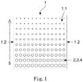
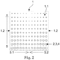
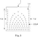
- the Figures 1 to 5 show top views of five embodiments of perforated, thermoplastic polyvinyl butyral films 1.
- the polyvinyl butyral films 1 had dimensions of 300 mm by 300 mm and a uniform thickness of 0.7 mm. Their surface 1.1 was evenly smooth. They had two parallel edges 1.2.
- the in Figures 1 to 5 The embodiments of the grid field shown are square patterns of the square dimensions mentioned above. The good feasibility of the hole patterns shown was proven. The pattern was then transferred to the windshields and side windows, in which case only part of the window has a grid field and no recesses are made in another part.
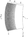
- Figure 7 shows such a windshield with a grid field.
- the Figure 1 had a grid field 3 with round perforations 4 as the perforation 2.
- the mass gradient running along the parallel edges 1.2 was set by the fact that the clear widths of the round perforations 4 in each column of the grid field 3 became smaller and smaller.
- the perforation 2 of the Figure 2 essentially corresponded to the Figure 1 with the difference that, in addition to the mass gradient 5, there were also two mass gradients 5.1 at 5.2 arranged perpendicular thereto. These were set in that the clear widths of the perforations 4 in each line of the grid field 3 initially became smaller and smaller, in order then to rise again towards the edge 1.2.
- the perforation 2 of the Figure 3 had a complex grid field 3 with round holes 4 of the same size, which, however, were not arranged in a regular grid.
- the perforations 4 were arranged along an edge 1.2 in a straight line, whereas the majority of the perforations 4 were arranged in an upwardly decreasing number, equidistantly in the horizontal direction.
- the mass gradient 5 was set by a relatively large area without holes 4.
- the Figure 4 had a perforation 2 with a grid field 3, which consisted of elongated, identically aligned triangles 4 arranged parallel to the side edges 1.2.
- the mass gradient 5 resulted from this arrangement.
- the Figure 5 had a perforation 2 with a grid field 3, which was formed by elongated, identically aligned, "tie-shaped" perforations 4 arranged parallel to the side edges 1.2.
- the perforations 4 could also be interpreted as elongated trapezoids in which the longer of the two parallel edges was rounded.
- the holes 4 were nested within one another over short distances.
- the mass gradient 5 resulted from the fact that the clear width of the perforations 4 in the columns of the grid field 3 became smaller, whereas it remained the same in the rows.
- Figure 5 is an example of the fact that the rows of perforations (2,3,4) are offset from one another.
- the Figure 6 shows a cross section through a laminated glass pane 7.
- the individual panes 7.1 and 7.2 made of float glass had an area of 1 m 2 and were 1.4 mm thick. she were firmly bonded by a wedge-shaped polyvinyl butyral film 6 free of perforations. The wedge angle ⁇ was 0.75 mrad.
- the wedge-shaped polyvinyl butyral film 6 free of perforations was in each case produced by hot-pressing the perforated, thermoplastic polyvinyl butyral films according to FIGS Figures 1 to 5 manufactured.
- FIG. 11 shows a top view of the composite pane 7 from FIG Figure 6 before lamination.
- the composite pane 7 corresponds to a windshield after lamination.
- a perforated thermoplastic plastic film 1 is inserted between the two individual panes 7.1, 7.2 of the composite pane.
- the perforations 4 shown in the perforated film 1 are not true to scale. It is only intended to show an exemplary distribution and a size profile of the perforations.
- the ratio of the film material removed by means of perforations to the film material still present is also not true to scale.
- the perforated film 1 has three different areas in which the proportion of the material removed through perforations 4 differs. The second area lies between the first area and the third area.
- perforations 4 are made in the form of a uniform grid, the area of the perforations within the first area 9 being constant.
- the perforations 4 are made in the form of rows, which for example can run parallel to the engine edge.
- the second area 10 directly adjoins the first area 9 and also has perforations 4 arranged in rows.
- the perforations of this first Row of the second area 10 correspond in size to the size of the perforations 4 in the first area.
- the size of the perforations 4 in the second area 10 decreases in the direction of the roof edge of the composite pane 7, preferably continuously.
- the size progression of the perforations according to Figure 7 is particularly advantageous because in this way, after lamination of the arrangement, a composite pane with wedge foil can be produced in a simple manner.
- To generate the wedge is it is necessary to remove a larger proportion of the material in the lower, first area adjacent to the motor edge.
- No perforations are required in the upper, third area adjacent to the roof edge, as this area is usually not used as a HUD field and therefore no wedge profile of the film is necessary here.
- the second area lying between the first and third area serves as a transition area between these, in which the film shows a wedge course after lamination, preferably a continuous wedge course between the first and third area.
- a HUD field is preferably positioned within this second area, since the wedge course present there is particularly suitable for compensating for ghost images.
- Holes 4 shown are shown by way of example in the form of circular recesses. However, these can also take any of the forms disclosed within the scope of this invention.
- the perforations preferably have the trapezoidal basic shape already described, the longer of the two parallel edges of the trapezoid being rounded.
- a further second mass gradient between the side edges of the composite pane run essentially perpendicular to the first mass gradient.
Landscapes
- Chemical & Material Sciences (AREA)
- Engineering & Computer Science (AREA)
- Manufacturing & Machinery (AREA)
- Materials Engineering (AREA)
- Health & Medical Sciences (AREA)
- Chemical Kinetics & Catalysis (AREA)
- Medicinal Chemistry (AREA)
- Polymers & Plastics (AREA)
- Organic Chemistry (AREA)
- Laminated Bodies (AREA)
- Joining Of Glass To Other Materials (AREA)
Description
- Die vorliegende Erfindung betrifft perforierte, thermoplastische Kunststofffolien.
- Außerdem betrifft die vorliegende Erfindung die Verwendung der perforierten, thermoplastischen Kunststofffolien zur Herstellung von Perforierungen freier, thermoplastischer, keilförmiger Folien.
- Des Weiteren betrifft die vorliegende Erfindung ein Verfahren zur Herstellung von Perforierungen freier, thermoplastischer keilförmiger Folien aus den perforierten, thermoplastischen Kunststofffolien.
- Verbundglasscheiben (VGS) werden heutzutage an vielen Orten, insbesondere im Fahrzeugbau, verwendet. Dabei umfasst der Begriff Fahrzeug unter anderem Straßenfahrzeuge, Flugzeuge, Schiffe, landwirtschaftliche Maschinen oder auch Arbeitsgeräte.
- Auch in anderen Bereichen werden Verbundglasscheiben verwendet. Hierzu zählen beispielsweise Gebäudeverglasungen oder Informationsdisplays, z.B. in Museen oder als Werbedisplays.
- Dabei weist eine Verbundglasscheibe im Allgemeinen zwei Glasflächen oder Scheiben auf, die auf eine Zwischenschicht laminiert sind. Die Scheiben selbst können eine Krümmung aufweisen und sind in aller Regel von konstanter Dicke. Die Zwischenschicht weist in aller Regel ein thermoplastisches Material, vorzugsweise Polyvinylbutyral (PVB), einer vorbestimmten Dicke, z.B. 0,76 mm, auf.
- Da die Verbundglasscheiben häufig in Bezug auf einen Betrachter geneigt sind, kommt es zu Doppelbildern. Diese Doppelbilder sind dadurch bedingt, dass einfallendes Licht in aller Regel nicht vollständig durch beide Scheiben tritt, sondern dass zumindest ein Teil des Lichtes reflektiert wird und erst danach durch die zweite Scheibe tritt.
- Diese Doppelbilder sind insbesondere bei Dunkelheit wahrnehmbar, vor allem bei stark einstrahlenden Lichtquellen, wie z.B. die Scheinwerfer eines entgegenkommenden Fahrzeugs.
- Diese Doppelbilder sind extrem störend und ein Sicherheitsproblem.
- Häufig werden Verbundglasscheiben auch als Head-Up-Display (HUD) zur Anzeige von Informationen verwendet. Dabei wird mittels einer Projektionsvorrichtung ein Bild auf die Verbundglasscheiben projiziert, um dem Betrachter eine Information in Sichtfeld einzublenden. Im Fahrzeugbereich wird die Projektionseinrichtung z.B. auf dem Armaturenbrett angeordnet, so dass das projizierte Bild auf der nächstliegenden Glasfläche der zum Betrachter hin geneigten Verbundglasscheibe in Richtung des Betrachters reflektiert wird (vgl. z.B. das europäische Patent
EP 0 420 228 B1 oder die deutsche OffenlegungsschriftDE 10 2012 211 729 A1 ). - Hier tritt wiederum ein Teil des Lichts in die Verbundglasscheiben ein und wird nun z.B. an der inneren Grenzschicht der vom Betrachter aus gesehen weiter außen liegenden Glasfläche und der Zwischenschicht reflektiert und tritt anschließend versetzt aus der Verbundglasscheibe aus. Auch hier tritt ein ähnlicher Effekt, der Effekt der Geisterbilder, in Bezug auf das darzustellende Bild auf.
- Eine reine klassische Kompensation von Geisterbildern führt dazu, dass eine Überkompensation für Doppelbilder in Transmission zu beobachten ist. Dies führt dazu, dass der jeweilige Betrachter irritiert wird oder im schlimmsten Fall eine Fehlinformation erhält. Bislang wird versucht dieses Problem dadurch zu lösen, dass die Oberflächen der Scheiben nicht mehr parallel, sondern in einem festen Winkel angeordnet werden. Dies wird zum Beispiel dadurch erreicht, dass die Zwischenschicht eine keilförmige Zwischenschicht mit kontinuierlich linear und/oder nichtlinear ansteigender und/oder abnehmender Dicke aufweist. Im Fahrzeugbau wird typischerweise die Dicke so variiert, dass am unteren Ende der Verbundglasscheibe hin zum Motorraum die kleinste Dicke vorgesehen ist, während die Dicke zum Dach hin ansteigt.
- Verbundglasscheiben dieser Art mit keilförmiger Zwischenschicht und die optischen Gesetze, auf denen sie beruhen, sind an sich bekannt und werden beispielsweise in den internationalen Patentanmeldungen
WO 2015/134836 A1 ,WO 2015/086234 A1 ,WO 2015/086233 A1 undWO 2015/078989 A1 , den amerikanischen PatentenUS 8,451,541 B2 ,US 7,060,343 B2 ,US 6,881,472 B2 ,US 6,636,370 B2 ,US 5,812,332 A undUS 5,013,134 , den europäischen PatentschriftenEP 2 767 393 A1 ,EP 2 017 237 A1 undEP 1 800 855 A1 oder den deutschen OffenlegungsschriftenDE 10 2007 095 323 A1 ,DE 196 11 483 A1 undDE 195 35 053 A1 beschrieben. - Der erforderliche Keilwinkelverlauf und das daraus resultierende Dickenprofil der Zwischenschicht muss für jede Scheibenform gesondert berechnet werden. Bislang wird das erfindungsgemäße Dickenprofil durch Verwendung einer entsprechenden Schlitzdüse bei der Extrusion der Folie, oder aber durch gezieltes in Form bringen der mit einem entsprechenden Temperaturprofil aufgeheizten Folie erreicht. Es ist aber auch möglich, durch nachträgliches Abtragen der Folie das gewünschte Dickenprofil zu erzeugen. Diese Methoden können auch kombiniert werden, indem beispielsweise das Dickenprofil in der einen Richtung durch eine entsprechende Schlitzdüse bei der Extrusion und in der anderen Richtung durch nachträgliches entsprechendes in Form bringen der Folie erzeugt wird.
- Bei dieser Art der Herstellung treten jedoch Probleme auf.
- Wenn die hergestellten Folienbahnen für die Lagerung und den Versand zu Rollen aufgewickelt werden, nehmen die Rollen eine zunehmend konische Form an, was bei der Handhabung und dem Transport der Rollen zu Schwierigkeiten führt. Um diese Schwierigkeiten zu vermeiden, ist es aus dem europäischen Patent
EP 0 647 329 B1 bekannt, Folienbahnen herzustellen, die an beiden Rändern auf einer Breite von wenigstens 20 % der Bandbreite ein gleichmäßiges Dickenprofil und ein anschließendes keilförmige Dickenprofil aufweisen, dass sich jeweils bis zur Mitte der Folienbahn erstreckt. Diese nur im Mittelfeld keilförmig ausgebildeten Folienbahnen können dann auf herkömmliche zylindrische Kerne bis zu einer Länge von etwa 300 m aufgewickelt werden. Die Bahnen werden für die Weiterverarbeitung in der Mitte durchgetrennt, auf die gewünschte Form zugeschnitten und so mit den Einzelglasscheiben zusammengelegt, dass der keilförmigen Teil der Bahn im unteren Bereich der Windschutzscheibe liegt, indem das HUD-Sichtfenster angeordnet ist. Bei diesem Verfahren müssen aber die herausragenden Teile der Folien mit gleichmäßigem Dickenprofil entfernt werden und als unbrauchbarer Abfall entsorgt werden. Außerdem bereitet diese Art und Weise der Herstellung große Probleme bei der Herstellung variabler Dickenprofile in zwei lateralen Dimensionen. - Demgegenüber besteht die Aufgabe der vorliegenden Erfindung, ein neues Verfahren zur Herstellung von keilförmigen Kunststofffolien als Zwischenschichten für Verbundglasscheiben zu finden, das präzise, hinsichtlich der Formgebung flexibel und materialsparend ist und keilförmige Kunststofffolien liefert, die auch in horizontal und vertikal gekrümmten Verbundglasscheiben, wie z.B. Panoramascheiben, Doppelbilder und Geisterbilder wirksam unterdrückt.
- Diese und weitere Aufgaben werden nach dem Vorschlag der Erfindung durch die Folien und das Verfahren mit den Merkmalen der unabhängigen Patentansprüche gelöst. Vorteilhafte Ausgestaltungen der Erfindung sind durch die Merkmale der Unteransprüche gegeben.
- Gegenstand der vorliegenden Erfindung sind demnach perforierte, thermoplastische Kunststofffolien mit vorzugsweise mindestens zwei parallelen Kanten. Wobei zu beachten ist, dass die Kunststofffolien nachdem sie in Form gebracht sind, nicht zwingend parallele Kanten aufweisen. Die perforierten, thermoplastischen Kunststofffolien sind über ihre gesamte Fläche hinweg von gleichmäßiger oder von im Wesentlichen gleicher Dicke.
- Hier und im Folgenden bedeutet der Begriff »im Wesentlichen«, dass die betreffende Größe von dem exakten Wert in einem Maße abweicht, das das anwendungstechnische Profil nicht beeinflusst.
- Vorzugsweise sind die perforierten, thermoplastischen Kunststofffolien transparent. Als transparent im Sinne der Erfindung wird dann eine Kunststofffolie verstanden, die eine Transmission im sichtbaren Spektralbereich >70 % aufweist. Für Kunststofffolien für den Fahrzeugbereich, die nicht im verkehrsrelevanten Sichtfeld eines Fahrers liegen, beispielsweise für Dachscheiben, kann die Transmission aber auch viel geringer sein, beispielsweise >5 %.
- Bevorzugt sind die perforierten, thermoplastischen Kunststofffolien farblos. Insbesondere sind sie klar.
- Vorzugsweise werden als thermoplastische Kunststoffe Polyvinylbutyral (PVB), Ethylenvinylacetat (EVA), Polyethylenterephthalat (PET), Polyurethan (PU), Polypropylen (PP), Polyacrylat, Polyethylen (PE), Polycarbonat (PC), Polymethylmethacrylat, Polyvinylchlorid, Polyacetalharz, Gießharze, Polyacrylate, fluorierte Ethylen-Propylen-Copolymerisate, Polyvinylfluorid, Ethylen-Tetrafluorethylen-Copolymerisate sowie Copolymere und Gemische davon verwendet, besonders bevorzugt werden Polyvinylbutyral (PVB), Ethylenvinylacetat (EVA) oder Polyurethan (PU) verwendet. Insbesondere wird PVB verwendet.
- Die Dicke der perforierten, thermoplastischen Kunststofffolien kann breit variieren und richtet sich in erster Linie nach dem vorgegebenen Verwendungszweck.
- Die perforierten, thermoplastischen Kunststofffolien können durch eine oder auch durch mehrere übereinander angeordnete thermoplastische Folien ausgebildet werden, wobei die Dicke der perforierten, thermoplastischen Kunststofffolien bevorzugt von 0,25 mm bis 2 mm und typischerweise 0,38 mm oder 0,76 mm beträgt.
- Die Perforierung der perforierten, thermoplastischen Kunststofffolien wird jeweils von mindestens einem, insbesondere einem Rasterfeld aus einer Vielzahl von Aussparungen (Lochungen) gebildet. Das Rasterfeld erstreckt sich über einen Teil der gesamten Fläche oder über die gesamte Fläche der perforierten, thermoplastischen Kunststofffolien. Dabei sind die Lochungen derart angeordnet, dass in mindestens einer Richtung, vorzugsweise in Richtung der parallelen Kanten, ein Massegradient resultiert.
- »Massegradient« bedeutet, dass aufgrund der Perforierung sich die Masse der perforierten, thermoplastischen Kunststofffolien in dieser Richtung ändert. Die Änderung kann linear, stufenförmig oder Form einer konkaven oder konvexen Kurve verlaufen.
- Liegt nur ein solcher Massegradient vor, dann haben die perforierten, thermoplastischen Kunststofffolien in Querrichtung, d.h. in der Richtung senkrecht zu den parallelen Kanten, eine gleichmäßige oder im Wesentlichen gleichmäßige Dicke.
- In einer vorteilhaften Ausführungsform weisen die perforierten, thermoplastischen Kunststofffolien mindestens einen senkrecht oder in Wesentlichen senkrecht zu dem vorstehend beschriebenen Massegradienten verlaufenden Massegradienten auf. Anders gesagt, verläuft dieser mindestens zweite Massegradient jeweils quer oder im Wesentlichen quer zu den perforierten, thermoplastischen Kunststofffolien. Der mindestens zweite Massegradient bedeutet, dass aufgrund der Perforierung sich die Masse der perforierten, thermoplastischen Kunststofffolien in dieser Richtung ändert. Die Änderung kann ebenfalls linear, stufenförmig oder in Form einer konkaven oder konvexen Kurve verlaufen.
- In einer möglichen Ausführungsform der perforierten, thermoplastischen Kunststofffolie verläuft der Massegradient kurvenförmig, wobei die Größe der Aussparungen mindestens ein Kurvenminimum oder Kurvenmaximum zwischen zwei gegenüberliegenden Kanten der Kunststofffolie durchläuft. Bei Herstellung einer Verbundscheibe werden diese Extremwerte des Größenverlaufs vor Lamination der Scheibe so positioniert, dass sie innerhalb des als Head-Up-Display genutzten Bereichs der Scheibe liegen. Dabei können auch mehrere Kurvenminima oder Kurvenmaxima vorliegen, beispielsweise zwei Minima oder zwei Maxima, wobei je ein Minimum oder Maximum im Bereich eines HUD-Feldes liegt. Dies hat den Vorteil, dass im Bereich des Head-Up-Displays ein über die Größe der Aussparungen genau definierbarer Keilwinkel entsteht, der eine sehr exakte Kompensation von Ghostbildern ermöglicht. Besonders eine Kunststofffolie mit mehr als einem Maximum oder Minimum ist mittels des erfindungsgemäßen Verfahrens auf einfache Art und Weise mit genau definierbaren Keilwinkeln herstellbar. Dies ist ein entscheidender Vorteil gegenüber dem Stand der Technik.
- Darüber hinaus ist es bei Windschutzscheiben mit jeweils einem (variablen oder konstanten) Keilwinkel in zwei laterale Richtungen möglich, HUD-Felder in Windschutzscheiben näher am sogenannten A-Holm der Karosserie zu platzieren. In der Regel weisen Windschutzscheiben in dieser Scheibenregion eine in Richtung des A-Holm verlaufende Biegung auf. Mittels des erfindungsgemäßen Verfahrens lässt sich sehr einfach eine Keilfolie erzeugen, die eine solche Biegung ausgleichen kann. Im Bereich des HUD-Feldes werden somit unerwünschte Verzerrungen oder Ghostbilder vermieden.
- Die Lochungen in einem Rasterfeld können von unterschiedlicher oder von gleicher Größe sein. Dabei können sie von unterschiedlichem oder gleichem Umriss sein.
- Der Umriss der Lochungen kann breit variieren und deshalb dem jeweiligen Verwendungszweck hervorragend angepasst werden. Vorzugsweise weisen die Lochungen einen kreisförmigen, einen ovalen oder einen elliptischen Umriss oder einen mindestens dreieckigen Umriss auf.
- Beispiele geeigneter mindestens dreieckiger Umrisse sind dreieckige, viereckige, fünfeckige, sechseckige, siebeneckige, achteckige, neuneckige und zehneckige, vorzugsweise dreieckige und viereckige, Umrisse. Diese Umrisse können mindestens eine abgerundete Ecke und/oder Kante haben. Vorzugsweise sind diese Umrisse bzw. die entsprechenden Lochungen in der Richtung parallel oder im Wesentlichen parallel zu den parallelen Kanten der perforierten, thermoplastischen Kunststofffolien gestreckt.
- Dreieckige oder trapezförmige Aussparungen (Lochungen) sind bevorzugt, da diese ein weites Spektrum von Keilwinkeln zugänglich machen. Trapezförmige Aussparungen sind besonders bevorzugt, da die spitz zulaufenden Ecken eines Dreiecks schwieriger zuzuschneiden sind als die stumpfen Eckwinkel eines Trapezes. Insbesondere ist mindestens eine der beiden parallelen Kanten des Trapezes abgerundet. Bevorzugt ist die längere der beiden parallelen Kanten des Trapezes abgerundet. Dadurch wird eine weitere Vereinfachung des Verfahrens bewerkstelligt, da einerseits die spitzen Winkel an der Basis des Trapezes wegfallen und somit der Zuschnitt erleichtert wird und andererseits das Schließen der Aussparung beim Laminiervorgang erleichtert wird. Die Wahl von Aussparungen mit einer trapezförmigen Grundform, die an der Basis des Trapezes tropfenförmig auslaufen, hat sich in Versuchen als besonders vorteilhaft erwiesen. Die tropfenförmige Form an der Basis des Trapezes ist vorteilhaft, da der bei Zufließen der Aussparung im Laminationsprozess das Material von beiden Seiten des Tropfens den gleichen Weg zurückzulegen hat. Dadurch ist ein sehr exaktes Zufließen der Lochung möglich.
- In einer bevorzugten Ausführungsform sind die Lochungen in Form eines Schachbrettmusters über die perforierte thermoplastische Folie verteilt. Dies ist vorteilhaft, da das Material auf diese Weise gleichmäßig entfernt wird und so das Zufließen der Lochungen erleichtert wird. Außerdem ist zu beobachten, dass die perforierten thermoplastischen Folien selbst über eine höhere mechanische Stabilität verfügen wenn die Aussparungen in Form eines Schachbrettmusters angebracht sind. Diese erhöhte Stabilität ist vorteilhaft bei einem manuellen oder automatisierten Transport der perforierten Folien.
- Bevorzugt variiert die Größe der einzelnen Aussparungen im Schachbrettmuster je nach gewünschtem Keilwinkel und Keilwinkelverlauf der späteren Keilfolie. Besonders bevorzugt steigt die Größe der Aussparungen in einer Richtung kontinuierlich oder diskontinuierlich an, wodurch die Richtung des entstehenden Keils der Keilfolie festgelegt wird.
- Aufgrund ihrer vorteilhaften anwendungstechnischen Eigenschaften können die erfindungsgemäßen perforierten, thermoplastischen Kunststofffolien zahlreichen Verwendungszwecken zugeführt werden. Insbesondere werden sie aber zur Herstellung von im Verbund von Perforierungen freien, keilförmigen Folien verwendet.
- Auch diese von Perforierungen freien, keilförmigen Folien können aufgrund ihrer vorteilhaften anwendungstechnischen Eigenschaften, insbesondere was die Präzision ihrer Keilwinkel betrifft, zahlreichen Verwendungszwecken zugeführt werden. Insbesondere werden sie aber als Zwischenschicht zum haftfesten Verbinden zweier Scheiben zwecks Herstellung einer Verbundscheibe verwendet.
- Die Scheiben können je nach ihrer Funktion opak oder transparent sein. Sie können aus Materialien, ausgewählt aus der Gruppe, bestehend aus Holz, Papier, Metall, Kunststoff und Glas sowie Gemischen und Verbunden dieser Materialien, aufgebaut sein. Besonders bevorzugt werden Glas und/oder Kunststoff als transparentes Material verwendet.
- Die erste Scheibe und/oder die zweite Scheibe der transparenten Verbundscheibe enthalten bevorzugt Glas, besonders bevorzugt Flachglas, Floatglas, Quarzglas, Borosilikatglas oder Kalk-Natron-Glas, oder klare Kunststoffe, vorzugsweise starre klare Kunststoffe, insbesondere Polyethylen, Polypropylen, Polycarbonat, Polymethylmethacrylat, Polystyrol, Polyamid, Polyester, Polyvinylchlorid und/oder Gemische davon.
- Die Dicke der transparenten Scheiben kann breit variieren und so hervorragend den Erfordernissen des Einzelfalls angepasst werden. Vorzugsweise werden Scheiben mit den Standardstärken von 1,0 mm bis 25 mm, bevorzugt von 1,4 mm bis 5 mm für Fahrzeugglas und bevorzugt von 4 mm bis 25 mm für Möbel, Geräte und Gebäude, insbesondere für elektrische Heizkörper, verwendet. Die Größe der Scheiben kann breit variieren und richtet sich nach der Größe der erfindungsgemäßen Vorrichtung. Die erste Scheibe und gegebenenfalls die zweite Scheibe weisen beispielsweise im Fahrzeugbau und Architekturbereich übliche Flächen von 200 cm2 bis zu 20 m2 auf.
- Die transparente Scheibe kann eine beliebige dreidimensionale Form aufweisen. Vorzugsweise hat die dreidimensionale Form keine Schattenzonen, so dass sie beispielsweise durch Kathodenzerstäubung beschichtet werden kann. Bevorzugt sind die Substrate planar oder leicht oder stark in einer Richtung oder in mehreren Richtungen des Raumes gebogen. Insbesondere werden planare Substrate verwendet. Die transparenten Scheiben können farblos oder gefärbt sein.
- Diese Verbundscheiben, insbesondere die Verbundglasscheiben, können hervorragend als bewegliches funktionales und/oder dekoratives Einzelstück und/oder als Einbauteil in Möbeln, Geräten und Gebäuden sowie in Fortbewegungsmitteln zur Fortbewegung auf dem Lande, in der Luft, oder zu Wasser, insbesondere aber in Kraftfahrzeugen, beispielsweise als bewegliche Heckscheibe und Seitenscheibe und/oder bewegliches Glasdach verwendet werden. Vorzugsweise sind die Verbundglasscheiben als Windschutzscheiben ausgeführt.
- Erfindungsgemäß werden die von Perforierungen freien, keilförmigen Folien durch ein Verfahren hergestellt, bei dem man in einem ersten Verfahrensschritt den mindestens einen Massegradienten, der zur Erzeugung einer von Perforierungen freien, keilförmigen Folie mit mindestens einem gewünschten Keilwinkel aus einer perforierten, thermoplastischen Kunststofffolie berechnet. Computerprogramme, mit denen solche Berechnungen routinemäßig durchgeführt werden können, sind bekannt.
- In einem zweiten Verfahrensschritt wird das Rasterfeld der perforierten, thermoplastischen Kunststofffolie mit den Lochungen, das für die Erzeugung des gewünschten mindestens einen Massegradienten erforderlich ist, berechnet. Auch hierfür stehen Computerprogramme, mit denen solche Berechnungen routinemäßig durchgeführt werden können, zur Verfügung.
- In einem dritten Verfahrensschritt wird das berechnete Rasterfeld mit den Lochungen aus einer thermoplastischen Kunststofffolie mit einer über ihre gesamte Fläche hinweg gleichmäßigen Dicke angebracht. In dieser Weise werden die vorstehend beschriebenen, jeweils gewünschten, perforierten, thermoplastischen Kunststofffolien erhalten. Die Aussparungen (Lochungen) können beispielsweise durch Schneiden oder Ausstanzen oder auch jedes andere dem Fachmann bekannte Verfahren zur Erzeugung von Aussparungen hergestellt werden.
- In einem vierten Verfahrensschritte werden die perforierten, thermoplastischen Kunststofffolien auf die jeweils gewünschten Größen zugeschnitten und in einem fünften Verfahrensschritt jeweils zwischen zwei Scheiben platziert. Die beiden Verfahrensschritte drei und vier können auch in umgekehrter Reihenfolge ausgeführt werden.
- In einem sechsten Verfahrensschritt werden die zugeschnittenen, perforierten, thermoplastischen Kunststofffolien zwischen jeweils zwei Scheiben heiß verpresst. Dabei werden die Lochungen durch den fließenden Kunststoff geschlossen und es bilden sich die gewünschten, von Perforierungen freien, keilförmigen Folien mit mindestens einem gewünschten Keilwinkel.
- Die in dem fünften Verfahrensschritt verwendeten Scheiben können eine antihaftende Oberfläche aufweisen, so dass nach dem sechsten Verfahrensschritt die zugeschnittenen keilförmigen Folien zur weiteren Verwendung entnommen, gelagert und transportiert werden können. In diesem Fall kann das Material der Scheiben beliebig aus der Gruppe, bestehend aus Holz, Papier, Metall, Kunststoff und Glas sowie Gemischen und Verbunden dieser Materialien, ausgewählt werden.
- Erfindungsgemäß ist es jedoch bevorzugt, dass die Scheiben keine antihaftenden Oberflächen aufweisen, so dass die von Perforierungen freien, keilförmigen Folien die beiden Scheiben haftfest zu Verbundscheiben, wie sie vorstehend beispielhaft beschrieben werden, verbinden. In diesem Fall enthalten die Scheiben Glas oder Kunststoff. Die keilförmige Folie und die beiden Einzelscheiben sind bevorzugt transparent und weisen besonders bevorzugt eine Transmission von mindestens 70% im sichtbaren Bereich des Spektrums auf. Das Material der Einzelscheiben ist bevorzugt aus der Gruppe, bestehend aus Flachglas, Floatglas, Quarzglas, Borosilikatglas, Kalk-Natron-Glas, Polyethylen, Polypropylen, Polycarbonat, Polymethylmethacrylat, Polystyrol, Polyamid, Polyester, Polyvinylchlorid und/oder Gemischen davon, ausgewählt.
- Beschrieben, aber nicht Gegenstand der vorliegenden Erfindung ist darüber hinaus eine Verbundscheibe erhältlich nach dem erfindungsgemäßen Verfahren. Die Verbundscheibe umfasst mindestens zwei Einzelscheiben enthaltend Glas oder Kunststoff sowie mindestens eine keilförmige Folie. Zur Herstellung der Verbundscheibe wird bevorzugt zunächst ein Rasterfeld von Aussparungen (Lochungen) gemäß dem erfindungsgemäßen Verfahren in einer thermoplastischen Kunststofffolie angebracht, so dass eine perforierte, thermoplastische Kunststofffolie entsteht. Die perforierte Kunststofffolie weist dabei erfindungsgemäß in mindestens einer Richtung zwischen zwei gegenüberliegenden Kanten einen Massegradienten auf. Die perforierte thermoplastische Kunststofffolie wird daraufhin auf die gewünschte Größe zugeschnitten und zwischen den Einzelscheiben platziert, wobei die Reihenfolge dieser beiden Schritte beliebig ist. Anschließend wird der Schichtstapel aus thermoplastischer Kunststofffolie und Scheiben zu einer Verbundscheibe laminiert.
- Die Verbundscheibe lässt sich für den Fachmann in einfacher Art und Weise von Verbundscheiben nach dem Stand der Technik unterscheiden, da die Perforationen der Kunststofffolie im Produkt schwach sichtbar bleiben, auch nachdem die Folie im Laminationsprozess verschmolzen wurde. Wird eine starke Lichtquelle auf die Kante der Verbundscheibe gerichtet, so sind die Perforationen der Kunststofffolie selbst nach Lamination bei näherer Betrachtung erkennbar. Für den Endverbraucher ist dies nicht störend, da die Kante der Verbundscheibe nach Einbau im Fahrzeug eingefasst ist und von dieser Seite somit kein Licht einstrahlt. Bei Einstrahlung von Licht durch die Scheibe hindurch sind die vormaligen Perforationen nach Lamination nicht mehr erkennbar, wodurch eine Beeinträchtigung des Sichtkomforts vermieden wird.
- In einer möglichen Ausführungsform verläuft der Keilwinkel kurvenförmig zwischen den den A-Holmen benachbarten Scheibenkanten. Dabei wird eine perforierte thermoplastische Folie eingesetzt, bei der die Größe der Aussparungen mindestens ein Kurvenminimum oder Kurvenmaximum zwischen zwei gegenüberliegenden Kanten der Kunststofffolie durchläuft, wie bereits für die erfindungsgemäße perforierte Kunststofffolie beschrieben. Bevorzugt entsprechen diese beiden gegenüberliegenden Kanten den zu den A-Holmen der Verbundscheibe benachbarten Scheibenkanten. Zwischen Motorkante und Dachkante verläuft dabei bevorzugt ebenfalls ein Keilwinkel. Dadurch wird ein bidirektionaler Keilwinkel erhalten. Derartige Keilwinkelverläufe sind beispielsweise in
WO2015086233 beschrieben und lassen sich unter Verwendung der erfindungsgemäßen thermoplastischen Kunststofffolie einfach und wirtschaftlich herstellen. - Die Verbundscheibe weist bevorzugt eine Zwischenschicht mit einem Keilwinkel von 0,1 mrad bis 1 mrad, besonders bevorzugt 0,3 mrad bis 1 mrad, insbesondere 0,75 mrad bis 1 mrad, beispielsweise 0,75 mrad bis 0,8 mrad auf. Das erfindungsgemäße Herstellungsverfahren macht demnach auch derartig große Keilwinkel von über 0,75 mrad zugänglich, während bekannte kommerziell erhältliche Keilfolien maximale Keilwinkel von 0,70 bis 0,73 mrad aufweisen.
- In einer bevorzugten Ausführungsform der Verbundscheibe handelt es sich um die Windschutzscheibe eines Kraftfahrzeugs. Alternativ handelt es sich um die Seitenscheibe eines Kraftfahrzeugs. Sofern die Scheibe eine Seitenscheibe betrifft, handelt es sich bei der im Folgenden als Motorkante bezeichneten Kante der Scheibe um die im Einbauzustand an der Türkante liegenden Seite der Scheibe. Die Dachkante der Scheibe entspricht hingegen bei einer Seitenscheibe der dem A-Holm des Fahrzeugs benachbarten Kante der Verbundscheibe. Der Begriff A-Holm ist dem Fachmann wohlbekannt und bezeichnet im Fahrzeugbereich die feststehende zwischen Windschutzscheibe und Seitenscheibe befindliche Karosseriesäule.
- Bevorzugt haben die Lochungen eine Breite von maximal 10 mm, bevorzugt maximal 6 mm, beispielsweise 5,2 mm oder kleiner. Die Breite der Lochungen ist dabei als die maximale Abmessung einer einzelnen Aussparung, gemessen in Richtung einer in der Mitte der Motorkante an diese angelegte Tangente, definiert.
- Eine bevorzugte Ausführungsform der Verbundscheibe wird hergestellt, indem die perforierte Kunststofffolie so zwischen den Scheiben eingelegt wird, dass der mindestens eine Massegradient der perforierten thermoplastischen Kunststofffolie zwischen Dachkante und Motorkante der Verbundscheibe, bezogen auf den Einbauzustand in einem Kraftfahrzeug, verläuft. Der Massenanteil der Kunststofffolie in Nachbarschaft zur Motorkante der Scheibe ist dabei bevorzugt geringer als der benachbart zur Dachkante befindliche Anteil der Kunststofffolie. Als Motorkante wird in diesem Sinne die, nach Montage in einer Fahrzeugkarosserie, dem Motorraum zugewandte Kante der Verbundscheibe bezeichnet, während die gegenüberliegende Dachkante an den Dachhimmel des Fahrzeugs grenzt.
- Bevorzugt ist das Rasterfeld mit Lochungen nur im unteren, der Motorkante benachbarten, Bereich der Verbundscheibe angebracht und erstreckt sich von der Motorkante aus bis zu einer Scheibenhöhe von maximal 75% der Gesamtscheibenhöhe, besonders bevorzugt bis zu einer Scheibenhöhe von maximal 50% der Gesamtscheibenhöhe, insbesondere 40% der Gesamtscheibenhöhe.
- In einer besonders bevorzugten Ausführungsform wird die Verbundscheibe unter Verwendung einer thermoplastischen perforierten Kunststofffolie mit Aussparungen von trapezförmiger Grundform hergestellt. Die beiden zueinander parallelen Seiten der Trapeze sind vor Lamination der Verbundscheibe im Wesentlichen parallel zur Dachkante bzw. Motorkante der späteren Verbundscheibe ausgerichtet. Bevorzugt ist der Abstand der längeren der beiden parallelen Seiten des Trapezes zur Motorkante geringer als der Abstand der kürzeren der beiden parallelen Seiten des Trapezes zur Motorkante. Die längere der parallelen Seiten des Trapezes ist somit in Richtung der Motorkante orientiert. Eine oder mehrere Kanten der trapezförmigen Grundform sind bevorzugt abgerundet. In einer besonders bevorzugten Ausführungsform verfügt die längere der beiden parallelen Seiten des Trapezes über eine tropfenförmige Ausbuchtung. Diese trapezförmigen Aussparungen mit tropfenförmiger Ausbuchtung an der Basis des Trapezes sind in Form eines Schachbrettmusters über die perforierte thermoplastische Folie verteilt. Die Fläche der einzelnen Aussparungen steigt dabei bevorzugt von der Dachkante der späteren Verbundscheibe zur Motorkante der Verbundscheibe an, so dass benachbart zur Motorkante mehr Material entfernt wird als in Nachbarschaft zur Dachkante. Wie bereits erwähnt ist dies vorteilhaft im Hinblick auf ein exaktes Ausschneiden der Aussparungen, ein gutes Zufließen der Aussparungen und eine kontinuierliche keilförmige Materialverteilung im Laminationsprozess.
- Es versteht sich, dass die vorstehend genannten und nachstehend näher erläuterten Merkmale nicht nur in den angegebenen Kombinationen und Konfigurationen, sondern auch in anderen Kombinationen und Konfigurationen oder in Alleinstellung einsetzbar sind, ohne den Rahmen der vorliegenden Erfindung zu verlassen.
- Die Erfindung wird nun anhand von Ausführungsbeispielen näher erläutert, wobei Bezug auf die beigefügten Figuren genommen wird. Es zeigen in vereinfachter nicht maßstäblicher Darstellung:
- Figur 1
- eine Draufsicht auf eine erste Ausführungsform einer perforierten, thermoplastischen Kunststofffolie 1;
- Figur 2
- eine Draufsicht auf eine zweite Ausführungsform einer perforierten, thermoplastischen Kunststofffolie 1;
- Figur 3
- eine Draufsicht auf eine dritte Ausführungsform einer perforierten, thermoplastischen Kunststofffolie 1;
- Figur 4
- eine Draufsicht auf eine vierte Ausführungsform einer perforierten, thermoplastischen Kunststofffolie 1;
- Figur 5
- eine Draufsicht auf eine fünfte Ausführungsform einer perforierten thermoplastischen Kunststofffolie 1;
- Figur 6
- einen Querschnitt durch eine Verbundscheibe 7 mit keilförmiger Folie;
- Figur 7
- Einzelscheiben 7.1, 7.2 und perforierte thermoplastische Kunststofffolie 1 der Verbundscheibe 7 als Windschutzscheibe vor Lamination.
- In den
Figuren 1 bis 7 haben die Bezugszeichen die folgende Bedeutung: - 1
- perforierte, thermoplastische Kunststofffolie
- 1.1
- Oberfläche der perforierten, thermoplastischen Kunststofffolie 1
- 1.2
- parallele Seitenkanten der perforierten, thermoplastischen Kunststofffolie 1
- 2
- Perforierung
- 3
- Rasterfeld
- 4
- Aussparung, Lochung
- 5
- Massegradient
- 5.1, 5.2
- Massegradient senkrecht zum Massegradienten 5
- 6
- von Perforierungen freie, keilförmige Folie
- 7
- Verbundscheibe
- 7.1, 7.2
- Einzelscheiben der Verbundscheibe 7
- 8
- Keilwinkel
- 9
- erster Bereich
- 10
- zweiter Bereich
- 11
- dritter Bereich
- Die
Figuren 1 bis 5 zeigen Draufsichten auf fünf Ausführungsformen von perforierten, thermoplastischen Polyvinylbutyral-Folien 1. Die Polyvinylbutyral-Folien 1 wiesen eine Abmessung von 300 mm mal 300 mm und eine gleichmäßige Dicke von 0,7 mm auf. Ihre Oberfläche 1.1 war gleichmäßig glatt. Sie hatten zwei parallele Kanten 1.2. Bei den inFiguren 1 bis 5 gezeigten Ausführungsformen des Rasterfeldes handelt es sich um quadratische Muster der oben genannten quadratischen Abmessung. Dabei wurde die gute Ausführbarkeit der gezeigten Lochmuster bewiesen. Danach wurde das Muster auf Windschutzscheiben und Seitenscheiben übertragen, wobei in diesem Fall nur ein Teil der Scheibe ein Rasterfeld aufweist und in einem anderen Teil keine Aussparungen angebracht sind.Figur 7 zeigt eine solche Windschutzscheibe mit Rasterfeld. - Die
Figur 1 wies als Perforierung 2 ein Rasterfeld 3 mit runden Lochungen 4 auf. Der längs der parallelen Kanten 1.2 verlaufende Massegradient wurde dadurch eingestellt, dass die lichten Weiten der runden Lochungen 4 in jeweils einer Spalte des Rasterfeldes 3 immer kleiner wurden. - Die Perforierung 2 der
Figur 2 entsprach im Wesentlichen derFigur 1 mit dem Unterschied, dass außer dem Massegradienten 5 noch zwei senkrecht hierzu angeordnete Massegradienten 5.1 an 5.2 vorhanden waren. Diese wurden eingestellt, indem in jeder Zeile des Rasterfeldes 3 die lichten Weiten der Lochungen 4 zunächst immer kleiner wurden, um dann zur Kante 1.2 hin wieder zu anzusteigen. - Die Perforierung 2 der
Figur 3 wies ein komplexes Rasterfeld 3 mit gleichgroßen runden Lochungen 4 auf, die indes nicht in einem regelmäßigen Raster angeordnet waren. So waren die Lochungen 4 längs einer Kante 1.2 in einer geraden Linie angeordnet, wogegen die Mehrzahl der Lochungen 4 in nach oben abnehmender Anzahl, äquidistant in horizontaler Richtung angeordnet waren. Der Massegradient 5 wurde durch eine verhältnismäßig große Fläche ohne Lochungen 4 eingestellt. - Die
Figur 4 wies eine Perforierung 2 mit einem Rasterfeld 3 auf, das aus lang gestreckten, gleich ausgerichteten, parallel zu den Seitenkanten 1.2 angeordneten Dreiecken 4 bestand. Der Massegradient 5 ergab sich aus dieser Anordnung. - Die
Figur 5 wies eine Perforierung 2 mit einem Rasterfeld 3 auf, das von lang gestreckten, gleich ausgerichteten, parallel zu den Seitenkanten 1.2 angeordneten, "krawattenförmigen" Lochungen 4 gebildet wurde. Die Lochungen 4 konnten auch als lang gestreckte Trapeze, bei denen die längere der beiden parallelen Kanten abgerundet war, aufgefasst werden. Die Lochungen 4 waren auf kurzen Strecken ineinander geschachtelt. Der Massegradient 5 resultierte daraus, dass die lichte Weite der Lochungen 4 in den Spalten des Rasterfeldes 3 kleiner wurde, wogegen sie in den Zeilen gleich blieb.Figur 5 ist ein Beispiel dafür, dass die Reihen von Lochungen (2,3,4) zueinander versetzt sind. - Die
Figur 6 zeigt einen Querschnitt durch eine Verbundglasscheibe 7. Die Einzelscheiben 7.1 und 7.2 aus Floatglas wiesen eine Fläche von 1 m2 auf und waren 1,4 mm dick. Sie waren durch eine von Perforierungen freie, keilförmige Polyvinylbutyral-Folie 6 haftfest verbunden. Der Keilwinkel 8 war 0,75 mrad. - Die von Perforierungen freie, keilförmige Polyvinylbutyral-Folie 6 wurde jeweils durch Heißpressen der entsprechend berechneten und hergestellten perforierten, thermoplastischen Polyvinylbutyral-Folien gemäß den
Figuren 1 bis 5 hergestellt. - Es erwies sich als ein ganz besonderer Vorteil, dass durch dieses Verfahren der Keilwinkel besonders präzise eingestellt werden konnte.
-
Figur 7 zeigt eine Draufsicht der Verbundscheibe 7 ausFigur 6 vor Lamination. Die Verbundscheibe 7 entspricht nach Lamination einer Windschutzscheibe. Zwischen den beiden Einzelscheiben 7.1, 7.2 der Verbundscheibe ist eine perforierte thermoplastische Kunststofffolie 1 eingelegt. Die in der perforierten Folie 1 gezeigten Lochungen 4 sind nicht maßstabsgetreu. Es soll lediglich eine beispielhafte Verteilung und ein Größenverlauf der Lochungen gezeigt werden. Das Verhältnis des mittels Lochungen entfernten Folienmaterials zu dem noch vorhandenen Folienmaterial ist ebenfalls nicht maßstabsgetreu. Die perforierte Folie 1 verfügt dabei über drei verschiedene Bereiche, in denen sich der Anteil des durch Lochungen 4 entfernten Materials unterscheidet. Der zweite Bereich liegt dabei zwischen dem ersten Bereich und dem dritten Bereich. Im ersten Bereich 9, der benachbart zur Motorkante der Verbundscheibe 7 liegt, sind Lochungen 4 in Form eines gleichmäßigen Rasters angebracht, wobei die Fläche der Lochungen innerhalb des ersten Bereichs 9 konstant ist. Die Lochungen 4 sind in Form von Reihen angebracht, die beispielsweise parallel zur Motorkante verlaufen können. Der zweite Bereich 10 grenzt unmittelbar an den ersten Bereich 9 an und verfügt ebenfalls über in Reihen angeordnete Lochungen 4. Eine von der Motorkante aus betrachtet erste Reihe von Lochungen 4 innerhalb des zweiten Bereichs 10 grenzt dabei an den ersten Bereich 9. Die Lochungen dieser ersten Reihe des zweiten Bereichs 10 entsprechen in ihrer Größe der Größe der Lochungen 4 im ersten Bereich. Im weiteren Verlauf nimmt die Größe der Lochungen 4 im zweiten Bereich 10 in Richtung der Dachkante der Verbundscheibe 7 ab, bevorzugt kontinuierlich ab. Im dritten Bereich 11 befinden sich keine Lochungen. Der Größenverlauf der Lochungen gemäßFigur 7 ist besonders vorteilhaft, da auf diese Weise nach Lamination der Anordnung auf einfache Weise eine Verbundscheibe mit Keilfolie erzeugt werden kann. Zur Erzeugung des Keils ist es notwendig im unteren, der Motorkante benachbarten, ersten Bereich einen größeren Anteil des Materials zu entfernen. Im oberen, der Dachkante benachbarten, dritten Bereich sind keine Lochungen erforderlich, da dieser Bereich üblicherweise nicht als HUD-Feld genutzt wird und somit hier kein Keilverlauf der Folie notwendig ist. Der zwischen erstem und drittem Bereich liegende zweite Bereich dient als Übergangsbereich zwischen diesen, in dem die Folie nach Lamination einen Keilverlauf, bevorzugt einen kontinuierlichen Keilverlauf zwischen erstem und drittem Bereich zeigt. Ein HUD-Feld wird bevorzugt innerhalb dieses zweiten Bereichs positioniert, da der dort vorliegende Keilverlauf besonders geeignet ist zur Kompensation von Ghostbildern. Die inFigur 7 gezeigten Lochungen 4 sind beispielhaft in Form von kreisförmigen Aussparungen dargestellt. Diese können jedoch ebenso jede beliebige im Rahmen dieser Erfindung offenbarte Form annehmen. Bevorzugt weisen die Lochungen die bereits beschriebene trapenzförmige Grundform auf, wobei die längere der beiden parallelen Kanten des Trapezes abgerundet ist. Des Weiteren kann zusätzlich zu dem inFigur 7 beschriebenen ersten Massegradienten ein weiterer zweiter Massegradient zwischen den Seitenkanten der Verbundscheibe im Wesentlichen senkrecht zum ersten Massegradienten verlaufen.
Claims (13)
- Perforierte, thermoplastische Kunststofffolien (1) von über ihre gesamte Fläche (1.1) hinweg gleichmäßiger Dicke, geeignet zur Verwendung als Zwischenschicht einer Verbundscheibe, worin die Perforierung (2) von mindestens einem Rasterfeld (3) aus einer Vielzahl von Lochungen (4) gebildet ist, das sich über einen Teil der gesamten Fläche (1.1) oder über die gesamte Fläche (1.1) hinweg erstreckt, wobei die Lochungen (4) derart angeordnet sind, dass in mindestens einer Richtung in den Kunststofffolien (1) ein Massegradient (5) resultiert, wobei Massegradient bedeutet, dass sich aufgrund der Perforierung (2) die Masse der perforierten, thermoplastischen Kunststofffolien (1) in dieser Richtung ändert.
- Kunststofffolien (1) nach Anspruch 1, dadurch gekennzeichnet, dass sie mindestens einen senkrecht zu dem Massegradienten (5) verlaufenden Massegradienten (5.1, 5.2, .... 5.n) mit n = eine ganze Zahl >2 aufweisen.
- Kunststofffolien (1) nach Anspruch 1 oder 2, dadurch gekennzeichnet, dass die Lochungen (4) in einem Rasterfeld (3) von unterschiedlicher oder von gleicher Größe sind.
- Kunststofffolien (1) nach einem der Ansprüche 1 bis 3, dadurch gekennzeichnet, dass die Lochungen (4) in einem Rasterfeld (3) von unterschiedlichem oder gleichem Umriss sind und die Reihen von Lochungen (4) zueinander versetzt sind.
- Kunststofffolien (1) nach Anspruch 4, dadurch gekennzeichnet, dass die Lochungen (4) mindestens einen kreisförmigen, einen ovalen, einen elliptischen Umriss oder eine Kombination davon oder einen mindestens dreieckigen Umriss aufweisen.
- Kunststofffolien (1) nach Anspruch 5, dadurch gekennzeichnet, dass die mindestens dreieckigen Lochungen (4) mindestens eine abgerundete Ecke und/oder Kante haben.
- Kunststofffolien (1) nach einem der Ansprüche 1 bis 6, dadurch gekennzeichnet, dass die Lochungen (4) in Form eines Schachbrettmusters angeordnet sind.
- Verwendung der perforierten, thermoplastischen Kunststofffolien gemäß einem der Ansprüche 1 bis 7 zur Herstellung von von Perforierungen freien, keilförmigen Folien (6).
- Verwendung nach Anspruch 8, wobei die von Perforierungen freien, keilförmigen Folien (6) als Zwischenschicht zum haftfesten Verbinden zweier Scheiben (7.1) und (7.2) zwecks Herstellung einer Verbundscheibe (7) dienen.
- Verfahren zur Herstellung von von Perforierungen freien, keilförmigen Folien (6), umfassend die Verfahrensschritte(A) Berechnung des mindestens einen Massegradienten (5, 5.1, 5.2 .... 5n), worin n die vorstehend angegebene Bedeutung hat, der zur Erzeugung einer von Perforierungen freien, keilförmigen Folie (6) mit mindestens einem gewünschten Keilwinkel (8) aus einer perforierten, thermoplastischen Kunststofffolie (1) gemäß einem der Ansprüche 1 bis 9 erforderlich ist,(B) Berechnung des Rasterfeldes (3) mit Lochungen (4) der perforierten, thermoplastischen Kunststofffolie (1), das für die Erzeugung des gewünschten mindestens einen Massegradienten (5, 5.1, 5.2 .... 5n), worin n die vorstehend angegebene Bedeutung hat, erforderlich ist, und(C) Anbringen des berechneten Rasterfeldes (3) mit den Lochungen (4) aus einer thermoplastischen Kunststofffolie mit einer über die gesamte Fläche hinweg gleichmäßigen Dicke und Erhalt der gewünschten perforierten, thermoplastischen Kunststofffolie (1) gemäß einem der Ansprüche 1 bis 9
sowie(D) Zuschneiden der perforierten, thermoplastischen Kunststofffolie (1) auf die gewünschte Größe,(E) Platzieren der zugeschnittenen, perforierten, thermoplastischen Kunststofffolie (1) zwischen zwei Einzelscheiben (7.1) und (7.2) und(F) Heißverpressen der zugeschnittenen, perforierten, thermoplastischen Kunststofffolie (1) zwischen den beiden Scheiben (7.1) und (7.2) unter Bildung einer von Perforierungen freien, keilförmigen Folie (6) mit mindestens einem gewünschten Keilwinkel (8). - Verfahren nach Anspruch 10, dadurch gekennzeichnet, dass die im Verfahrensschritt (E) verwendeten Einzelscheiben (7.1) und (7.2) eine antihaftende Oberfläche aufweisen und dass nach dem Verfahrensschritt (F) die zugeschnittenen, keilförmigen Folien (6) zur weiteren Verwendung entnommen und gelagert werden.
- Verfahren nach Anspruch 10, dadurch gekennzeichnet, dass die in den Verfahrensschritten (D) und (F) verwendeten Einzelscheiben (7.1) und (7.2) keine antihaftenden Oberflächen aufweisen, so dass die keilförmige Folie (6) die beiden Scheiben (7.1) und (7.2) als Zwischenschicht (6) unter Bildung einer Verbundscheibe (7) haftfest verbindet und die Scheiben (7.1, 7.2) Glas oder Kunststoff umfassen.
- Verfahren nach Anspruch einem der Ansprüche 10 bis 12, dadurch gekennzeichnet, dass das Material der perforierten, thermoplastischen Kunststofffolien (1) aus der Gruppe, bestehend aus Polyvinylbutyral (PVB), Ethylenvinylacetat (EVA), Polyurethan (PU), und/oder Copolymerisaten und Gemischen hiervon, ausgewählt wird.
Applications Claiming Priority (2)
| Application Number | Priority Date | Filing Date | Title |
|---|---|---|---|
| EP16159872 | 2016-03-11 | ||
| PCT/EP2017/054013 WO2017153166A1 (de) | 2016-03-11 | 2017-02-22 | Perforierte, thermoplastische kunststofffolien und ihre verwendung zur herstellung keilförmiger folien |
Publications (2)
| Publication Number | Publication Date |
|---|---|
| EP3426618A1 EP3426618A1 (de) | 2019-01-16 |
| EP3426618B1 true EP3426618B1 (de) | 2020-09-09 |
Family
ID=55589664
Family Applications (1)
| Application Number | Title | Priority Date | Filing Date |
|---|---|---|---|
| EP17705667.8A Active EP3426618B1 (de) | 2016-03-11 | 2017-02-22 | Perforierte, thermoplastische kunststofffolien und ihre verwendung zur herstellung keilförmiger folien |
Country Status (6)
| Country | Link |
|---|---|
| EP (1) | EP3426618B1 (de) |
| CN (1) | CN107614456B (de) |
| ES (1) | ES2834005T3 (de) |
| HU (1) | HUE052683T2 (de) |
| PL (1) | PL3426618T3 (de) |
| WO (1) | WO2017153166A1 (de) |
Families Citing this family (1)
| Publication number | Priority date | Publication date | Assignee | Title |
|---|---|---|---|---|
| ES2902173T3 (es) | 2019-06-25 | 2022-03-25 | Saint Gobain | Panel de material compuesto de vehículo con área de sensor y capa intermedia termoplástica curvada en el área de sensor |
Family Cites Families (20)
| Publication number | Priority date | Publication date | Assignee | Title |
|---|---|---|---|---|
| US5812332A (en) | 1989-09-28 | 1998-09-22 | Ppg Industries, Inc. | Windshield for head-up display system |
| US5013134A (en) | 1989-09-28 | 1991-05-07 | Hughes Aircraft Company | Ghost-free automotive head-up display employing a wedged windshield |
| DE69218007T2 (de) | 1992-06-25 | 1997-08-28 | Du Pont | Zwischenschichte für windschutzscheiben mit head-up-display und verfahren zur herstellung der schichten |
| DE19535053A1 (de) | 1994-10-04 | 1996-04-11 | Volkswagen Ag | Gekrümmte Verbundscheibe |
| DE19611483A1 (de) | 1995-09-21 | 1997-10-02 | Volkswagen Ag | Gekrümmte Verbundscheibe |
| US20030171730A1 (en) * | 2002-02-14 | 2003-09-11 | Kelly William G. F. | Three-dimensional apertured film |
| JP2007223883A (ja) | 2005-12-26 | 2007-09-06 | Asahi Glass Co Ltd | 車両用合せガラス |
| CN102976637B (zh) | 2006-05-12 | 2016-03-30 | 积水化学工业株式会社 | 夹层玻璃用中间膜及夹层玻璃 |
| CN101888927B (zh) | 2007-12-07 | 2013-05-29 | 法国圣戈班玻璃厂 | 由夹层玻璃制成的弧形机动车挡风玻璃 |
| NL2006223C2 (nl) * | 2011-02-17 | 2012-08-20 | Chameleon Lab B V | Gelaagde veiligheidsbeglazing met mogelijk geperforeerde tussenlaag. |
| JP5866152B2 (ja) * | 2011-06-30 | 2016-02-17 | スリーエム イノベイティブ プロパティズ カンパニー | 貫通孔を有する窓貼り用積層フィルム |
| KR20140035494A (ko) * | 2011-07-15 | 2014-03-21 | 덴끼 가가꾸 고교 가부시키가이샤 | 투광성 경질 기판 적층체의 제조방법 및 투광성 경질 기판 라미네이팅 장치 |
| CN102525747B (zh) * | 2012-01-30 | 2013-08-07 | 厦门延江工贸有限公司 | 打孔热塑性塑料薄膜卷材 |
| DE102012211729A1 (de) | 2012-07-05 | 2014-01-09 | Bayerische Motoren Werke Aktiengesellschaft | Kamerasystem zum Erfassen der Position eines Fahrers eines Kraftfahrzeugs |
| JP5910404B2 (ja) * | 2012-08-08 | 2016-04-27 | 旭硝子株式会社 | 積層体および車両用ルーフウインド |
| EP2767393A1 (de) | 2013-02-14 | 2014-08-20 | Kuraray Europe GmbH | Verfahren zur Herstellung von Verbundglaslaminaten mit Schalldämmeigenschaften durch Laminieren von Glasscheiben mit mindestens einer dünnen weichmacherarmen Schicht auf Basis von Polyvinylacetal und mindestens einer weiteren Schicht aus weichmacherhaltigem Polyvinylacetal |
| EP2878442A1 (de) | 2013-11-29 | 2015-06-03 | Kuraray Europe GmbH | Verbundglaslaminate mit Wärmestrahlung abschirmenden Eigenschaften |
| BR112016012378B1 (pt) | 2013-12-12 | 2021-09-28 | Saint-Gobain Glass France | Película termoplástica para uma chapa de vidro laminada tendo um inserto em cunha contínua não linear na direção vertical em algumas seções |
| CA2932635C (en) | 2013-12-12 | 2018-04-03 | Saint-Gobain Glass France | Thermoplastic film for a laminated glass pane having a nonlinear continuous wedge insert in the vertical and horizontal direction in some sections |
| US20150251377A1 (en) | 2014-03-07 | 2015-09-10 | Corning Incorporated | Glass laminate structures for head-up display system |
-
2017
- 2017-02-22 EP EP17705667.8A patent/EP3426618B1/de active Active
- 2017-02-22 CN CN201780000241.8A patent/CN107614456B/zh not_active Expired - Fee Related
- 2017-02-22 WO PCT/EP2017/054013 patent/WO2017153166A1/de not_active Ceased
- 2017-02-22 PL PL17705667.8T patent/PL3426618T3/pl unknown
- 2017-02-22 ES ES17705667T patent/ES2834005T3/es active Active
- 2017-02-22 HU HUE17705667A patent/HUE052683T2/hu unknown
Non-Patent Citations (1)
| Title |
|---|
| None * |
Also Published As
| Publication number | Publication date |
|---|---|
| CN107614456A (zh) | 2018-01-19 |
| CN107614456B (zh) | 2021-09-28 |
| HUE052683T2 (hu) | 2021-05-28 |
| WO2017153166A1 (de) | 2017-09-14 |
| ES2834005T3 (es) | 2021-06-16 |
| EP3426618A1 (de) | 2019-01-16 |
| PL3426618T3 (pl) | 2021-02-22 |
Similar Documents
| Publication | Publication Date | Title |
|---|---|---|
| DE69402207T2 (de) | Zwischenschicht mit runzeliger oberfläche | |
| EP3079902B1 (de) | Thermoplastische folie für eine verbundglas-scheibe mit nichtlinear-kontinuierlicher keileinlage in vertikaler richtung | |
| EP2883693B1 (de) | Verfahren zur Herstellung einer thermoplastischen Kombinationsfolie für eine Verbundglas-Scheibe | |
| EP3484707B1 (de) | Fahrzeug-verbundscheibe mit optimiertem strahlengang für einen daran angebrachten sensor | |
| EP3621804B1 (de) | Verfahren zur herstellung einer thermoplastischen kombinationsfolie | |
| WO2015086233A1 (de) | Thermoplastische folie für eine verbundglas-scheibe mit abschnittsweiser nichtlinear-kontinuierlicher keileinlage in vertikaler und horizontaler richtung | |
| EP2512795B1 (de) | Datenträgerkarte und verfahren zur herstellung einer datenträgerkarte | |
| EP3658371B1 (de) | Thermoplastische kunststofffolie für eine verbundglasscheibe | |
| WO2018010865A1 (de) | Verbundscheibe mit einer mehrlagigen verbundschicht und verfahren zu ihrer herstellung | |
| WO2017153167A1 (de) | Verfahren zur herstellung keilförmiger, thermoplastischer kunststofffolien und ihre verwendung | |
| EP2040917A1 (de) | Geprägte kunststofffolien für verbundverglasungen | |
| WO2020007610A1 (de) | Keilförmige mehrlagige zwischenschicht mit akustisch dämpfenden eigenschaften | |
| WO2020094419A1 (de) | Verbundscheibe für ein head-up-display | |
| WO2019038288A1 (de) | Verbundglas, verbundsicherheitsglas und verfahren zur herstellung eines solchen | |
| DE19622670C2 (de) | Lichtumlenkplatte mit zwei flächig ausgebildeten Elementen | |
| EP3630483B1 (de) | Verbundscheibe und verfahren zum herstellen der verbundscheibe | |
| EP3426618A1 (de) | Perforierte, thermoplastische kunststofffolien und ihre verwendung zur herstellung keilförmiger folien | |
| DE112021004646T5 (de) | Gekrümmte lichtlenkungsstrukturen | |
| WO2021254910A1 (de) | Verbundscheibe | |
| EP3630484B1 (de) | Gebogene verbundglasscheibe mit einem eingelassenen gebogenen zusammenhängenden display und verfahren zur herstellung derselben | |
| WO2020094420A1 (de) | Verbundscheibe mit keilförmigem querschnitt | |
| WO2020094421A1 (de) | Verbundscheibe für ein head-up-display | |
| DE202016008420U1 (de) | Verbundscheibe | |
| DE102013112421A1 (de) | Verkehrsleitelement und Frontelement dafür mit lichtreflektierender Sichtfläche | |
| WO2021063660A1 (de) | Verbundsicherheitsglasscheibe für head-up displays |
Legal Events
| Date | Code | Title | Description |
|---|---|---|---|
| STAA | Information on the status of an ep patent application or granted ep patent |
Free format text: STATUS: UNKNOWN |
|
| STAA | Information on the status of an ep patent application or granted ep patent |
Free format text: STATUS: THE INTERNATIONAL PUBLICATION HAS BEEN MADE |
|
| PUAI | Public reference made under article 153(3) epc to a published international application that has entered the european phase |
Free format text: ORIGINAL CODE: 0009012 |
|
| STAA | Information on the status of an ep patent application or granted ep patent |
Free format text: STATUS: REQUEST FOR EXAMINATION WAS MADE |
|
| 17P | Request for examination filed |
Effective date: 20180807 |
|
| AK | Designated contracting states |
Kind code of ref document: A1 Designated state(s): AL AT BE BG CH CY CZ DE DK EE ES FI FR GB GR HR HU IE IS IT LI LT LU LV MC MK MT NL NO PL PT RO RS SE SI SK SM TR |
|
| AX | Request for extension of the european patent |
Extension state: BA ME |
|
| DAV | Request for validation of the european patent (deleted) | ||
| DAX | Request for extension of the european patent (deleted) | ||
| STAA | Information on the status of an ep patent application or granted ep patent |
Free format text: STATUS: EXAMINATION IS IN PROGRESS |
|
| 17Q | First examination report despatched |
Effective date: 20190910 |
|
| RAP1 | Party data changed (applicant data changed or rights of an application transferred) |
Owner name: SAINT-GOBAIN GLASS FRANCE |
|
| GRAP | Despatch of communication of intention to grant a patent |
Free format text: ORIGINAL CODE: EPIDOSNIGR1 |
|
| STAA | Information on the status of an ep patent application or granted ep patent |
Free format text: STATUS: GRANT OF PATENT IS INTENDED |
|
| INTG | Intention to grant announced |
Effective date: 20200615 |
|
| GRAS | Grant fee paid |
Free format text: ORIGINAL CODE: EPIDOSNIGR3 |
|
| GRAA | (expected) grant |
Free format text: ORIGINAL CODE: 0009210 |
|
| STAA | Information on the status of an ep patent application or granted ep patent |
Free format text: STATUS: THE PATENT HAS BEEN GRANTED |
|
| AK | Designated contracting states |
Kind code of ref document: B1 Designated state(s): AL AT BE BG CH CY CZ DE DK EE ES FI FR GB GR HR HU IE IS IT LI LT LU LV MC MK MT NL NO PL PT RO RS SE SI SK SM TR |
|
| REG | Reference to a national code |
Ref country code: GB Ref legal event code: FG4D Free format text: NOT ENGLISH |
|
| REG | Reference to a national code |
Ref country code: AT Ref legal event code: REF Ref document number: 1311372 Country of ref document: AT Kind code of ref document: T Effective date: 20200915 Ref country code: CH Ref legal event code: EP |
|
| REG | Reference to a national code |
Ref country code: DE Ref legal event code: R096 Ref document number: 502017007145 Country of ref document: DE |
|
| REG | Reference to a national code |
Ref country code: IE Ref legal event code: FG4D Free format text: LANGUAGE OF EP DOCUMENT: GERMAN |
|
| REG | Reference to a national code |
Ref country code: RO Ref legal event code: EPE |
|
| REG | Reference to a national code |
Ref country code: NL Ref legal event code: FP |
|
| REG | Reference to a national code |
Ref country code: LT Ref legal event code: MG4D |
|
| REG | Reference to a national code |
Ref country code: SK Ref legal event code: T3 Ref document number: E 35865 Country of ref document: SK |
|
| PG25 | Lapsed in a contracting state [announced via postgrant information from national office to epo] |
Ref country code: GR Free format text: LAPSE BECAUSE OF FAILURE TO SUBMIT A TRANSLATION OF THE DESCRIPTION OR TO PAY THE FEE WITHIN THE PRESCRIBED TIME-LIMIT Effective date: 20201210 Ref country code: LT Free format text: LAPSE BECAUSE OF FAILURE TO SUBMIT A TRANSLATION OF THE DESCRIPTION OR TO PAY THE FEE WITHIN THE PRESCRIBED TIME-LIMIT Effective date: 20200909 Ref country code: BG Free format text: LAPSE BECAUSE OF FAILURE TO SUBMIT A TRANSLATION OF THE DESCRIPTION OR TO PAY THE FEE WITHIN THE PRESCRIBED TIME-LIMIT Effective date: 20201209 Ref country code: FI Free format text: LAPSE BECAUSE OF FAILURE TO SUBMIT A TRANSLATION OF THE DESCRIPTION OR TO PAY THE FEE WITHIN THE PRESCRIBED TIME-LIMIT Effective date: 20200909 Ref country code: NO Free format text: LAPSE BECAUSE OF FAILURE TO SUBMIT A TRANSLATION OF THE DESCRIPTION OR TO PAY THE FEE WITHIN THE PRESCRIBED TIME-LIMIT Effective date: 20201209 Ref country code: SE Free format text: LAPSE BECAUSE OF FAILURE TO SUBMIT A TRANSLATION OF THE DESCRIPTION OR TO PAY THE FEE WITHIN THE PRESCRIBED TIME-LIMIT Effective date: 20200909 Ref country code: HR Free format text: LAPSE BECAUSE OF FAILURE TO SUBMIT A TRANSLATION OF THE DESCRIPTION OR TO PAY THE FEE WITHIN THE PRESCRIBED TIME-LIMIT Effective date: 20200909 |
|
| PG25 | Lapsed in a contracting state [announced via postgrant information from national office to epo] |
Ref country code: LV Free format text: LAPSE BECAUSE OF FAILURE TO SUBMIT A TRANSLATION OF THE DESCRIPTION OR TO PAY THE FEE WITHIN THE PRESCRIBED TIME-LIMIT Effective date: 20200909 Ref country code: RS Free format text: LAPSE BECAUSE OF FAILURE TO SUBMIT A TRANSLATION OF THE DESCRIPTION OR TO PAY THE FEE WITHIN THE PRESCRIBED TIME-LIMIT Effective date: 20200909 |
|
| PG25 | Lapsed in a contracting state [announced via postgrant information from national office to epo] |
Ref country code: EE Free format text: LAPSE BECAUSE OF FAILURE TO SUBMIT A TRANSLATION OF THE DESCRIPTION OR TO PAY THE FEE WITHIN THE PRESCRIBED TIME-LIMIT Effective date: 20200909 Ref country code: SM Free format text: LAPSE BECAUSE OF FAILURE TO SUBMIT A TRANSLATION OF THE DESCRIPTION OR TO PAY THE FEE WITHIN THE PRESCRIBED TIME-LIMIT Effective date: 20200909 Ref country code: PT Free format text: LAPSE BECAUSE OF FAILURE TO SUBMIT A TRANSLATION OF THE DESCRIPTION OR TO PAY THE FEE WITHIN THE PRESCRIBED TIME-LIMIT Effective date: 20210111 |
|
| PGFP | Annual fee paid to national office [announced via postgrant information from national office to epo] |
Ref country code: LU Payment date: 20210210 Year of fee payment: 5 Ref country code: IT Payment date: 20210112 Year of fee payment: 5 Ref country code: RO Payment date: 20210127 Year of fee payment: 5 Ref country code: NL Payment date: 20210212 Year of fee payment: 5 Ref country code: FR Payment date: 20210112 Year of fee payment: 5 Ref country code: CZ Payment date: 20210128 Year of fee payment: 5 |
|
| REG | Reference to a national code |
Ref country code: HU Ref legal event code: AG4A Ref document number: E052683 Country of ref document: HU |
|
| PG25 | Lapsed in a contracting state [announced via postgrant information from national office to epo] |
Ref country code: AL Free format text: LAPSE BECAUSE OF FAILURE TO SUBMIT A TRANSLATION OF THE DESCRIPTION OR TO PAY THE FEE WITHIN THE PRESCRIBED TIME-LIMIT Effective date: 20200909 Ref country code: IS Free format text: LAPSE BECAUSE OF FAILURE TO SUBMIT A TRANSLATION OF THE DESCRIPTION OR TO PAY THE FEE WITHIN THE PRESCRIBED TIME-LIMIT Effective date: 20210109 |
|
| PGFP | Annual fee paid to national office [announced via postgrant information from national office to epo] |
Ref country code: GB Payment date: 20210210 Year of fee payment: 5 Ref country code: HU Payment date: 20210116 Year of fee payment: 5 Ref country code: ES Payment date: 20210310 Year of fee payment: 5 Ref country code: BE Payment date: 20210114 Year of fee payment: 5 Ref country code: TR Payment date: 20210219 Year of fee payment: 5 Ref country code: PL Payment date: 20201229 Year of fee payment: 5 Ref country code: DE Payment date: 20210209 Year of fee payment: 5 |
|
| REG | Reference to a national code |
Ref country code: DE Ref legal event code: R097 Ref document number: 502017007145 Country of ref document: DE |
|
| REG | Reference to a national code |
Ref country code: ES Ref legal event code: FG2A Ref document number: 2834005 Country of ref document: ES Kind code of ref document: T3 Effective date: 20210616 |
|
| PGFP | Annual fee paid to national office [announced via postgrant information from national office to epo] |
Ref country code: SK Payment date: 20210113 Year of fee payment: 5 |
|
| PLBE | No opposition filed within time limit |
Free format text: ORIGINAL CODE: 0009261 |
|
| STAA | Information on the status of an ep patent application or granted ep patent |
Free format text: STATUS: NO OPPOSITION FILED WITHIN TIME LIMIT |
|
| 26N | No opposition filed |
Effective date: 20210610 |
|
| PG25 | Lapsed in a contracting state [announced via postgrant information from national office to epo] |
Ref country code: SI Free format text: LAPSE BECAUSE OF FAILURE TO SUBMIT A TRANSLATION OF THE DESCRIPTION OR TO PAY THE FEE WITHIN THE PRESCRIBED TIME-LIMIT Effective date: 20200909 Ref country code: DK Free format text: LAPSE BECAUSE OF FAILURE TO SUBMIT A TRANSLATION OF THE DESCRIPTION OR TO PAY THE FEE WITHIN THE PRESCRIBED TIME-LIMIT Effective date: 20200909 |
|
| PG25 | Lapsed in a contracting state [announced via postgrant information from national office to epo] |
Ref country code: MC Free format text: LAPSE BECAUSE OF FAILURE TO SUBMIT A TRANSLATION OF THE DESCRIPTION OR TO PAY THE FEE WITHIN THE PRESCRIBED TIME-LIMIT Effective date: 20200909 |
|
| PG25 | Lapsed in a contracting state [announced via postgrant information from national office to epo] |
Ref country code: CH Free format text: LAPSE BECAUSE OF NON-PAYMENT OF DUE FEES Effective date: 20210228 Ref country code: LI Free format text: LAPSE BECAUSE OF NON-PAYMENT OF DUE FEES Effective date: 20210228 |
|
| PG25 | Lapsed in a contracting state [announced via postgrant information from national office to epo] |
Ref country code: IE Free format text: LAPSE BECAUSE OF NON-PAYMENT OF DUE FEES Effective date: 20210222 |
|
| REG | Reference to a national code |
Ref country code: DE Ref legal event code: R119 Ref document number: 502017007145 Country of ref document: DE |
|
| REG | Reference to a national code |
Ref country code: NL Ref legal event code: MM Effective date: 20220301 |
|
| REG | Reference to a national code |
Ref country code: SK Ref legal event code: MM4A Ref document number: E 35865 Country of ref document: SK Effective date: 20220222 |
|
| REG | Reference to a national code |
Ref country code: BE Ref legal event code: MM Effective date: 20220228 |
|
| GBPC | Gb: european patent ceased through non-payment of renewal fee |
Effective date: 20220222 |
|
| PG25 | Lapsed in a contracting state [announced via postgrant information from national office to epo] |
Ref country code: SK Free format text: LAPSE BECAUSE OF NON-PAYMENT OF DUE FEES Effective date: 20220222 Ref country code: RO Free format text: LAPSE BECAUSE OF NON-PAYMENT OF DUE FEES Effective date: 20220222 Ref country code: LU Free format text: LAPSE BECAUSE OF NON-PAYMENT OF DUE FEES Effective date: 20220222 Ref country code: CZ Free format text: LAPSE BECAUSE OF NON-PAYMENT OF DUE FEES Effective date: 20220222 |
|
| PG25 | Lapsed in a contracting state [announced via postgrant information from national office to epo] |
Ref country code: HU Free format text: LAPSE BECAUSE OF NON-PAYMENT OF DUE FEES Effective date: 20220223 |
|
| PG25 | Lapsed in a contracting state [announced via postgrant information from national office to epo] |
Ref country code: NL Free format text: LAPSE BECAUSE OF NON-PAYMENT OF DUE FEES Effective date: 20220301 Ref country code: FR Free format text: LAPSE BECAUSE OF NON-PAYMENT OF DUE FEES Effective date: 20220228 |
|
| PG25 | Lapsed in a contracting state [announced via postgrant information from national office to epo] |
Ref country code: GB Free format text: LAPSE BECAUSE OF NON-PAYMENT OF DUE FEES Effective date: 20220222 Ref country code: DE Free format text: LAPSE BECAUSE OF NON-PAYMENT OF DUE FEES Effective date: 20220901 |
|
| PG25 | Lapsed in a contracting state [announced via postgrant information from national office to epo] |
Ref country code: BE Free format text: LAPSE BECAUSE OF NON-PAYMENT OF DUE FEES Effective date: 20220228 |
|
| REG | Reference to a national code |
Ref country code: ES Ref legal event code: FD2A Effective date: 20230331 |
|
| REG | Reference to a national code |
Ref country code: AT Ref legal event code: MM01 Ref document number: 1311372 Country of ref document: AT Kind code of ref document: T Effective date: 20220222 |
|
| PG25 | Lapsed in a contracting state [announced via postgrant information from national office to epo] |
Ref country code: ES Free format text: LAPSE BECAUSE OF NON-PAYMENT OF DUE FEES Effective date: 20220223 Ref country code: AT Free format text: LAPSE BECAUSE OF NON-PAYMENT OF DUE FEES Effective date: 20220222 |
|
| PG25 | Lapsed in a contracting state [announced via postgrant information from national office to epo] |
Ref country code: PL Free format text: LAPSE BECAUSE OF NON-PAYMENT OF DUE FEES Effective date: 20220222 Ref country code: IT Free format text: LAPSE BECAUSE OF NON-PAYMENT OF DUE FEES Effective date: 20220222 |
|
| PG25 | Lapsed in a contracting state [announced via postgrant information from national office to epo] |
Ref country code: CY Free format text: LAPSE BECAUSE OF FAILURE TO SUBMIT A TRANSLATION OF THE DESCRIPTION OR TO PAY THE FEE WITHIN THE PRESCRIBED TIME-LIMIT Effective date: 20200909 |
|
| PG25 | Lapsed in a contracting state [announced via postgrant information from national office to epo] |
Ref country code: MK Free format text: LAPSE BECAUSE OF FAILURE TO SUBMIT A TRANSLATION OF THE DESCRIPTION OR TO PAY THE FEE WITHIN THE PRESCRIBED TIME-LIMIT Effective date: 20200909 |
|
| PG25 | Lapsed in a contracting state [announced via postgrant information from national office to epo] |
Ref country code: MT Free format text: LAPSE BECAUSE OF FAILURE TO SUBMIT A TRANSLATION OF THE DESCRIPTION OR TO PAY THE FEE WITHIN THE PRESCRIBED TIME-LIMIT Effective date: 20200909 |