EP3425875B1 - Method and apparatus for determining relative position - Google Patents
Method and apparatus for determining relative position Download PDFInfo
- Publication number
- EP3425875B1 EP3425875B1 EP17759125.2A EP17759125A EP3425875B1 EP 3425875 B1 EP3425875 B1 EP 3425875B1 EP 17759125 A EP17759125 A EP 17759125A EP 3425875 B1 EP3425875 B1 EP 3425875B1
- Authority
- EP
- European Patent Office
- Prior art keywords
- terminal device
- location information
- location
- relative
- marked
- Prior art date
- Legal status (The legal status is an assumption and is not a legal conclusion. Google has not performed a legal analysis and makes no representation as to the accuracy of the status listed.)
- Active
Links
Images


Classifications
-
- H—ELECTRICITY
- H04—ELECTRIC COMMUNICATION TECHNIQUE
- H04W—WIRELESS COMMUNICATION NETWORKS
- H04W4/00—Services specially adapted for wireless communication networks; Facilities therefor
- H04W4/02—Services making use of location information
- H04W4/023—Services making use of location information using mutual or relative location information between multiple location based services [LBS] targets or of distance thresholds
-
- H—ELECTRICITY
- H04—ELECTRIC COMMUNICATION TECHNIQUE
- H04L—TRANSMISSION OF DIGITAL INFORMATION, e.g. TELEGRAPHIC COMMUNICATION
- H04L67/00—Network arrangements or protocols for supporting network services or applications
- H04L67/50—Network services
- H04L67/52—Network services specially adapted for the location of the user terminal
-
- G—PHYSICS
- G01—MEASURING; TESTING
- G01S—RADIO DIRECTION-FINDING; RADIO NAVIGATION; DETERMINING DISTANCE OR VELOCITY BY USE OF RADIO WAVES; LOCATING OR PRESENCE-DETECTING BY USE OF THE REFLECTION OR RERADIATION OF RADIO WAVES; ANALOGOUS ARRANGEMENTS USING OTHER WAVES
- G01S5/00—Position-fixing by co-ordinating two or more direction or position line determinations; Position-fixing by co-ordinating two or more distance determinations
- G01S5/0009—Transmission of position information to remote stations
- G01S5/0072—Transmission between mobile stations, e.g. anti-collision systems
-
- G—PHYSICS
- G01—MEASURING; TESTING
- G01S—RADIO DIRECTION-FINDING; RADIO NAVIGATION; DETERMINING DISTANCE OR VELOCITY BY USE OF RADIO WAVES; LOCATING OR PRESENCE-DETECTING BY USE OF THE REFLECTION OR RERADIATION OF RADIO WAVES; ANALOGOUS ARRANGEMENTS USING OTHER WAVES
- G01S5/00—Position-fixing by co-ordinating two or more direction or position line determinations; Position-fixing by co-ordinating two or more distance determinations
- G01S5/02—Position-fixing by co-ordinating two or more direction or position line determinations; Position-fixing by co-ordinating two or more distance determinations using radio waves
- G01S5/0284—Relative positioning
-
- H—ELECTRICITY
- H04—ELECTRIC COMMUNICATION TECHNIQUE
- H04W—WIRELESS COMMUNICATION NETWORKS
- H04W4/00—Services specially adapted for wireless communication networks; Facilities therefor
- H04W4/20—Services signaling; Auxiliary data signalling, i.e. transmitting data via a non-traffic channel
-
- H—ELECTRICITY
- H04—ELECTRIC COMMUNICATION TECHNIQUE
- H04W—WIRELESS COMMUNICATION NETWORKS
- H04W8/00—Network data management
- H04W8/005—Discovery of network devices, e.g. terminals
-
- H—ELECTRICITY
- H04—ELECTRIC COMMUNICATION TECHNIQUE
- H04W—WIRELESS COMMUNICATION NETWORKS
- H04W8/00—Network data management
- H04W8/22—Processing or transfer of terminal data, e.g. status or physical capabilities
- H04W8/24—Transfer of terminal data
- H04W8/245—Transfer of terminal data from a network towards a terminal
Definitions
- the present invention relates to the field of computer technologies, and in particular, to a method and an apparatus for determining a relative location.
- a user not only can obtain, by using a terminal device, various services provided by an online system (for example, a website), but also can interact with other users by using the terminal device.
- an online system for example, a website
- location sharing based on a positioning service enables terminal devices to share locations with each other, so that users can learn the locations of other users.
- a location determined based on a positioning service is an absolute location.
- Terminal devices need to keep a smooth network connection to a server providing location data. Due to limited precision of the positioning data provided by the positioning service, terminal devices close to each other may obtain the same absolute location. Consequently, relative locations of the terminal devices cannot be differentiated.
- a specific device for example, an external location sensor
- each terminal device to differentiate relative locations of terminal devices by using the specific device.
- a relative location of each terminal device can be determined only by using the specific device. Without the specific device, the relative location of each terminal device cannot be determined. Consequently, such a method is limited.
- WO 2007/031844 A2 describes a network, and a method of operating a network.
- the network comprises a plurality of stations each able to transmit and receive data so that the network can transmit data between stations via at least one selected intermediate station.
- Each station transmits probe signals in broadcast fashion to other stations to gather a list of neighbor stations.
- the stations transmit position data and/or position determining data in at least some of the probe signals.
- the position data includes data indicative of the absolute or relative position of a station transmitting a probe signal
- the position determining data includes data usable by a station receiving a probe signal to determine the absolute or relative position of the station and/or other stations.
- Each station maintains position data and/or position determining data received from selected probing stations, and utilizes the data to determine the absolute or relative position of itself and/or other stations.
- the stations can determine the relative or absolute position of other stations in direct communication with themselves, and also of other stations not in direct communication with themselves.
- WO 2015/110019 A1 describes a location information sharing method and apparatus.
- the method includes: receiving, by a first terminal, current location information of a second terminal; and updating, by the first terminal and on a location display area of the first terminal, a previous location of the second terminal that is marked by using previous location information of the second terminal to a current location of the second terminal that is marked by using the current location information, where the previous location information is received by the first terminal before receiving the current location information.
- US 2008/254811 A1 describes a method of identifying mobile computing devices. The method includes sending a request from a first mobile computing device to a second mobile computing device for the location of the second mobile computing device, receiving the location of the second mobile computing device at the first mobile computing device, and providing a notification to one of the first and second mobile computing devices based upon the location of the second mobile computing device.
- Implementations of the present invention provide a method and an apparatus for determining a relative location, to resolve a problem in the existing technology that determining relative locations of terminal devices is greatly limited.
- the present invention is directed to the method for determining a relative location of a second terminal device relative to a first terminal device defined in claims 1 and 8. Apparatuses for determining a relative are defined in claims 13 and 14. The dependent claims depict advantageous embodiments of the present invention.
- the implementations of the present invention provide the method and apparatus for determining a relative location.
- the first terminal device that initiates relative location determining first generates the reference location information of the first terminal device, and sends the reference location information to the second terminal device, so that the second terminal device can use a location of the first terminal device as a reference location, to determine the marked location information of the second terminal device.
- the second terminal device sends the marked location information to the first terminal device, so that the first terminal device can determine the relative locations of the first terminal device and the second terminal device based on the reference location information of the first terminal device and the marked location information of the second terminal device.
- practicability of determining relative locations of a plurality of terminal devices by the terminal devices can be effectively improved without a need of using an external location sensing device.
- an implementation of the present invention provides a method for determining a relative location, to obtain the relative locations of the plurality of terminal devices without a need of using a specific device.
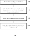
- FIG 1 illustrates a process of determining a relative location, according to an implementation of the present invention. The process includes the following steps.
- a first terminal device generates reference location information of the first terminal device.
- the first terminal device includes but is not limited to a computer terminal device, or a mobile device such as a smartphone, a tablet, or a notebook computer. In this implementation of the present invention, the first terminal device can be considered as an initiator of relative positioning.
- the reference location information reflects a relative location of the first terminal device. It is worthwhile to note that an absolute location of the first terminal device does not need to be accurately obtained because a relative location of each terminal device is determined in this implementation of the present invention.
- the first terminal device can be in due north, due south, etc. Or in another method of the present invention, the first terminal device can be in a central location in a positioning interface. Certainly, the described methods do not constitute a limitation on the present invention.
- a location corresponding to the reference location information generated by the first terminal device is used by another terminal device for reference, to determine a location of each terminal device. Therefore, after generating the reference location information of the first terminal device, the first terminal device needs to notify another terminal device. To be specific, the following step S102 is performed.
- S102 Send the reference location information to a second terminal device, so that the second terminal device sets location information of the second terminal device based on the reference location information, and uses the location information as marked location information.
- the second terminal device includes but is not limited to a computer terminal device, or a mobile device such as a smartphone, a tablet, or a notebook computer. In this implementation of the present invention, the second terminal device can be considered as a participant of the positioning for a relative location.
- the second terminal device After receiving the reference location information of the first terminal device, the second terminal device can determine a current location of the first terminal device, and use the location as a reference location to determine a location of the second terminal device.
- the second terminal device determines the location information of the second terminal device, and the location information of the second terminal device marks a current location of the second terminal device. Therefore, the location information of the second terminal device can be used as the marked location information.
- the location information of the second terminal device can be set by a user who uses the second terminal device, or can be set by the second terminal device (for example, under support of some applications, the second terminal device can perform location interaction with the first terminal device by using Bluetooth, infrared, etc., to determine the location information of the second terminal device, which is not limited here).
- the second terminal device sends the location information (that is, the marked location information) of the second terminal device to the first terminal device, so that the first terminal device determines relative locations of the terminal devices.
- the following step S104 is performed.
- S104 Determine relative locations of the first terminal device and the second terminal device based on the reference location information and the received marked location information.
- the reference location information reflects the current location of the first terminal device
- the marked location information reflects the current location of the second terminal device. Therefore, the relative locations of the first terminal device and the second terminal device can be determined.
- the first terminal device that initiates relative location determining first generates the reference location information of the first terminal device, and sends the reference location information to the second terminal device, so that the second terminal device can use the location of the first terminal device as the reference location, to determine the marked location information of the second terminal device. Then the second terminal device sends the marked location information to the first terminal device, so that the first terminal device can determine the relative locations of the first terminal device and the second terminal device based on the reference location information of the first terminal device and the marked location information of the second terminal device.
- practicability of determining relative locations of a plurality of terminal devices by the terminal devices can be effectively improved without a need of using an external location sensing device.
- sending the reference location information to the second terminal device in step S102 includes: determining, by the first terminal device, a group that includes the first terminal device, and sending the reference location information to each second terminal device in the group.
- the first terminal device initiates a relative location determining operation in the group that includes the first terminal device.
- the group can be an instant messaging group established by using a corresponding application, can be a local area network group established for terminal devices in the same local area network (for example, a WiFi network), or can be established on a network service platform under support of a corresponding server.
- the group can be established by the first terminal device, the second terminal device, or a network device (for example, a server providing a network service platform, or a router providing a local area network), which constitutes no limitation on the present invention here.
- each second terminal device receives the reference location information from the first terminal device, and each second terminal device marks location information of the second terminal device, and provides the location information for the first terminal device.
- the first terminal device can determine relative locations of all terminal devices (including the first terminal device) in the group. Therefore, the first terminal device needs to notify each second terminal device in the group of the relative locations of all the terminal devices, so that each second terminal device can learn the relative locations of all the terminal devices. Therefore, in this implementation of the present invention, the method further includes: determining, by the first terminal device, relative locations of the first terminal device and each second terminal device in the group, based on the received marked location information, and sending the determined relative location of each second terminal device to all second terminal devices in the group.
- All terminal devices in a group can learn relative locations of each other in such method.
- the first terminal device and the second terminal device can determine respective location information in the following methods.
- the first terminal device and the second terminal device can determine the reference location information and the marked location information by using corresponding positioning interfaces.
- the generating, by a first terminal device, reference location information of the first terminal device includes: generating, by the first terminal device in a positioning interface including a coordinate system, the reference location information of the first terminal device based on an origin of the coordinate system, where the first terminal device uses the origin of the coordinate system as a reference location of the first terminal device.
- the coordinate system is usually two-dimensional.
- the coordinate system can be three-dimensional.
- the three-dimensional coordinate system can present spatial relative locations of terminal devices when the terminal devices are on different floors of the same building. Certainly, it constitutes no limitation on the present invention here.
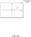
- FIG. 2a shows a positioning interface displayed by terminal device A (that is, the first terminal device). It can be seen from FIG. 2a that the positioning interface includes a two-dimensional coordinate system.
- terminal device A can determine an origin of the two-dimensional coordinate system as a reference location of terminal device A (that is, point LA). To be specific, terminal device A generates reference location information of terminal device A based on the origin of the two-dimensional coordinate system.
- sending the reference location information to the second terminal device includes: sending a positioning interface including the reference location information to the second terminal device.
- the second terminal device can mark a location of the second terminal device in the coordinate system of the positioning interface based on the positioning interface sent by the first terminal device, to set the marked location information, and feed back the marked location information to the first terminal device.
- receiving the marked location information sent by the second terminal device includes: receiving a positioning interface that is fed back by the second terminal device and that includes the marked location information of the second terminal device.
- terminal device A if terminal device A is in the same group as terminal device B1 and terminal device B2, terminal device A separately sends the positioning interface shown in FIG. 2a to terminal device B1 and terminal device B2. Based on this, terminal device B1 and terminal device B2 set respective marked location information in the coordinate system based on the positioning interface shown in FIG. 2a , and feed back the respective marked location information to terminal device A.
- point LB1 shown in FIG 2b is a location that is set by terminal device B1 in the positioning interface.
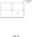
- point LB2 shown in FIG 2c is a location that is set by terminal device B2 in the positioning interface.
- terminal device A can determine relative locations of the three terminal devices in the same group based on the reference location (point LA) of terminal device A and the received marked location information (point LB 1 and point LB2) of terminal device B1 and terminal device B2.
- the two-dimensional coordinate system shown in FIG. 2a to FIG. 2d can also display coordinates of the locations.
- coordinates of point LA are (0, 0)
- coordinates of point LB1 are (1, 1). It constitutes no limitation on the present invention here.
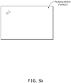
- Locations can be displayed by directly using a positioning interface (without a coordinate system) in addition to using a coordinate system.
- the generating, by a first terminal device, reference location information of the first terminal device includes: generating, by the first terminal device, the reference location information of the first terminal device in a positioning interface.
- the sending the reference location information to a second terminal device includes: sending the positioning interface to the second terminal device.
- the receiving the marked location information sent by the second terminal device includes: receiving a positioning interface that is fed back by the second terminal device and that includes the marked location information of the second terminal device.
- the first terminal device can determine a reference location of the first terminal device in the positioning interface in the method, to generate the reference location information.
- the first terminal device can use, based on an operation performed by a user in the positioning interface, a location selected by the user as the reference location of the first terminal device, to generate the reference location information.
- the first terminal device can use a predefined default location as the reference location of the first terminal device.
- the default location can be a central location of the positioning interface. It constitutes no limitation on the present invention here.
- the second terminal device can also set the marked location information of the second terminal device in the positioning interface sent by the first terminal device.
- the first terminal device After receiving the positioning interface fed back by the second terminal device, the first terminal device can further determine the relative locations of the first terminal device and the second terminal device.
- the first terminal device generates the reference location information based on the operation performed by the user in the positioning interface.
- point LA in FIG. 3a is a reference location of terminal device A.
- terminal device A Similar to the preceding example, if terminal device A is in the same group as terminal device B1 and terminal device B2, terminal device A separately sends a positioning interface including the reference location information to terminal device B1 and terminal device B2, and receives positioning interfaces that are fed back by terminal device B1 and terminal device B2 that both include marked location information.
- terminal device A determines relative locations of all terminal devices in the group.
- all terminal devices can conveniently set respective locations in the preceding two methods, and intuitively display all locations. Therefore, a subsequent operation can be performed after relative locations of terminal devices are determined.
- the method further includes: transferring information between the terminal devices in a specific sequence based on the relative locations of the terminal devices; or displaying a specific image on the terminal devices through screen combination based on the relative locations of the terminal devices.
- terminal device A can send information to terminal device B1
- terminal device B1 needs to transmit the information to terminal device B2 after receiving the information
- terminal device B2 needs to transmit the information to terminal device A.
- the three terminal devices can display a complete image through screen combination. As such, the images displayed on the three terminal devices can form a complete image.
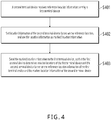
- an implementation of the present invention further provides a method for determining a relative location.
- a process of determining a relative location shown in FIG. 4 includes the following steps:
- the second terminal device can conveniently determine the relative locations of the second terminal device and the first terminal device.
- the second terminal device further receives marked location information of other second terminal devices sent by the first terminal device, so that each second terminal device in the group can determine relative locations of all terminal devices in the group. Details are omitted here for simplicity.
- the receiving, by a second terminal device, reference location information sent by a first terminal device includes: receiving, by the second terminal device, the positioning interface that is sent by the first terminal device and that includes the coordinate system. An origin of the coordinate system is used as a reference location of the first terminal device.
- the setting location information of the second terminal device based on the reference location information includes: receiving, by the second terminal device, an operation instruction of a user in the positioning interface; using, as a marked location of the second terminal device, a location selected by the user in the coordinate system in the positioning interface; and generating the marked location information.
- the sending the marked location information to the first terminal device includes: sending a positioning interface including the marked location information to the first terminal device.
- the receiving, by a second terminal device, reference location information sent by a first terminal device includes: receiving, by the second terminal device, a positioning interface that is sent by the first terminal device and that includes the reference location information.
- the setting location information of the second terminal device based on the reference location information includes: receiving an operation instruction of a user in the positioning interface; using, as a marked location of the second terminal device, a location selected by the user in the positioning interface; and generating the marked location information.
- the sending the marked location information to the first terminal device includes: sending a positioning interface including the marked location information to the first terminal device.
- Content of the preceding two methods is similar to the previously described content (content corresponding to FIG 2a to FIG. 2d and FIG. 3a to FIG. 3b ). Details are omitted here for simplicity.
- an implementation of the present invention provides the preceding methods for determining a relative location. As shown in FIG. 5 , based on the same idea, an implementation of the present invention further provides an apparatus for determining a relative location.
- the apparatus for determining a relative location in FIG. 5 includes: a reference location module 501, configured to generate reference location information of a first terminal device; a sending module 502, configured to send the reference location information to a second terminal device, so that the second terminal device sets location information of the second terminal device based on the reference location information, and uses the location information as marked location information; a receiving module 503, configured to receive the marked location information sent by the second terminal device; and a location determining module 504, configured to determine relative locations of the first terminal device and the second terminal device based on the reference location information and the received marked location information.
- the sending module 502 is configured to: determine a group including the first terminal device; and send the reference location information to each second terminal device in the group.
- the location determining module 504 is further configured to: determine relative locations of the first terminal device and each second terminal device in the group based on the received marked location information; and send the determined relative location of each second terminal device to all second terminal devices in the group.
- the reference location module 501 is configured to generate, in a positioning interface including a coordinate system, the reference location information of the first terminal device based on an origin of the coordinate system, where the first terminal device uses the origin of the coordinate system as a reference location of the first terminal device; the sending module 502 is configured to send a positioning interface including the reference location information to the second terminal device; and the receiving module 503 is configured to receive a positioning interface that is fed back by the second terminal device and that includes the marked location information of the second terminal device.
- the reference location module 501 is configured to generate the reference location information of the first terminal device in a positioning interface; the sending module 502 is configured to send the positioning interface to the second terminal device; and the receiving module 503 is configured to receive a positioning interface that is fed back by the second terminal device and that includes the marked location information of the second terminal device.
- the apparatus further includes: a processing module 505, configured to: transfer information between the terminal devices in a specific sequence based on the relative locations of the terminal devices; or display a specific image on the terminal devices through screen combination of images from different terminal devices based on the relative locations of the terminal devices.
- a processing module 505 configured to: transfer information between the terminal devices in a specific sequence based on the relative locations of the terminal devices; or display a specific image on the terminal devices through screen combination of images from different terminal devices based on the relative locations of the terminal devices.
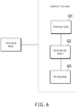
- an implementation of the present invention further provides an apparatus for determining a relative location.
- the apparatus includes: a receiving module 601, configured to receive reference location information sent by a first terminal device; a marked location module 602, configured to set location information of a second terminal device based on the reference location information, and use the location information as marked location information; and a sending module 603, configured to send the marked location information to the first terminal device, so that the first terminal device determines relative locations of the first terminal device and the second terminal device based on the reference location information of the first terminal device and the marked location information of the second terminal device.
- the receiving module 601 is configured to receive a positioning interface that is sent by the first terminal device and that includes a coordinate system, where an origin of the coordinate system is used as a reference location of the first terminal device;
- the marked location module 602 is configured to: receive an operation instruction of a user in the positioning interface; use, as a marked location of the second terminal device, a location selected by the user in the coordinate system in the positioning interface, and generate the marked location information;
- the sending module 603 is configured to send a positioning interface including the marked location information to the first terminal device.
- the receiving module 601 is configured to receive a positioning interface that is sent by the first terminal device and that includes the reference location information;
- the marked location module 602 is configured to: receive an operation instruction of a user in the positioning interface; use, as a marked location of the second terminal device, a location selected by the user in the positioning interface; and generate the marked location information;
- the sending module 603 is configured to send a positioning interface including the marked location information to the first terminal device.
- a computing device includes one or more processors (CPU), an input/output interface, a network interface, and a memory.
- the memory can include a non-persistent storage, a random access memory (RAM), a nonvolatile memory, and/or another form that are in a computer readable medium, for example, a read-only memory (ROM) or a flash memory (flash RAM).
- RAM random access memory
- flash RAM flash memory
- the memory is an example of the computer readable medium.
- the computer readable medium includes persistent, non-persistent, movable, and unmovable media that can implement information storage by using any method or technology.
- Information can be a computer readable instruction, a data structure, a program module, or other data.
- a computer storage medium includes but is not limited to a phase change memory (PRAM), a static random access memory (SRAM), a dynamic random access memory (DRAM), a random access memory (RAM) of another type, a read-only memory, an electrically erasable programmable read-only memory (EEPROM), a flash memory or another memory technology, a compact disc read-only memory (CD-ROM), a digital versatile disc (DVD), or another optical storage, a cassette, a cassette magnetic disk storage, or another magnetic storage device or any other non-transmission medium.
- PRAM phase change memory
- SRAM static random access memory
- DRAM dynamic random access memory
- RAM random access memory
- EEPROM electrically erasable programmable read-only memory
- CD-ROM compact disc
- the computer storage medium can be configured to store information that can be accessed by the computing device. Based on the definition in the present specification, the computer readable medium does not include transitory computer-readable media (transitory computer-readable media), for example, a modulated data signal and carrier.
- the implementations of the present invention can be provided as a method, a system, or a computer program product. Therefore, the present invention can use a form of hardware only implementations, software only implementations, or implementations with a combination of software and hardware. In addition, the present invention can use a form of a computer program product that is implemented on one or more computer-usable storage media (including but not limited to a magnetic disk storage, a CD-ROM, and an optical memory) that include computer-usable program code.
- computer-usable storage media including but not limited to a magnetic disk storage, a CD-ROM, and an optical memory
Landscapes
- Engineering & Computer Science (AREA)
- Computer Networks & Wireless Communication (AREA)
- Signal Processing (AREA)
- Remote Sensing (AREA)
- General Physics & Mathematics (AREA)
- Radar, Positioning & Navigation (AREA)
- Physics & Mathematics (AREA)
- Databases & Information Systems (AREA)
- Telephone Function (AREA)
- Telephonic Communication Services (AREA)
- User Interface Of Digital Computer (AREA)
- Mobile Radio Communication Systems (AREA)
- Position Fixing By Use Of Radio Waves (AREA)
- Navigation (AREA)
Applications Claiming Priority (2)
| Application Number | Priority Date | Filing Date | Title |
|---|---|---|---|
| CN201610112657.6A CN107135243B (zh) | 2016-02-29 | 2016-02-29 | 一种相对位置的确定方法及装置 |
| PCT/CN2017/073913 WO2017148274A1 (zh) | 2016-02-29 | 2017-02-17 | 一种相对位置的确定方法及装置 |
Publications (3)
| Publication Number | Publication Date |
|---|---|
| EP3425875A1 EP3425875A1 (en) | 2019-01-09 |
| EP3425875A4 EP3425875A4 (en) | 2019-10-30 |
| EP3425875B1 true EP3425875B1 (en) | 2021-08-25 |
Family
ID=59720750
Family Applications (1)
| Application Number | Title | Priority Date | Filing Date |
|---|---|---|---|
| EP17759125.2A Active EP3425875B1 (en) | 2016-02-29 | 2017-02-17 | Method and apparatus for determining relative position |
Country Status (6)
| Country | Link |
|---|---|
| US (1) | US11019453B2 (enExample) |
| EP (1) | EP3425875B1 (enExample) |
| JP (1) | JP7113751B2 (enExample) |
| CN (1) | CN107135243B (enExample) |
| TW (1) | TW201732730A (enExample) |
| WO (1) | WO2017148274A1 (enExample) |
Families Citing this family (4)
| Publication number | Priority date | Publication date | Assignee | Title |
|---|---|---|---|---|
| CN109587188B (zh) * | 2017-09-28 | 2021-10-22 | 阿里巴巴集团控股有限公司 | 确定终端设备之间相对位置关系的方法、装置及电子设备 |
| CN111221416B (zh) * | 2020-01-06 | 2021-12-07 | 腾讯科技(深圳)有限公司 | 一种虚拟道具分配的方法、服务器及终端设备 |
| US12313760B2 (en) | 2020-09-18 | 2025-05-27 | Qualcomm Incorporated | Relative location reporting for UE based positioning |
| CN116133090A (zh) * | 2021-11-12 | 2023-05-16 | 中国移动通信有限公司研究院 | 通信方法、装置、终端及存储介质 |
Family Cites Families (29)
| Publication number | Priority date | Publication date | Assignee | Title |
|---|---|---|---|---|
| JP3424328B2 (ja) * | 1994-06-21 | 2003-07-07 | 株式会社日立製作所 | 携帯端末装置 |
| JPH09178833A (ja) * | 1995-12-28 | 1997-07-11 | Sony Corp | 端末装置 |
| JP2002165258A (ja) | 2000-11-27 | 2002-06-07 | Yokohama Rubber Co Ltd:The | グループメンバーの所在位置認識装置及び所在位置認識プログラム並びにそれを記録した記録媒体 |
| JP2003121194A (ja) | 2001-10-19 | 2003-04-23 | Ttt Kk | 待ち合わせ場所表示方法 |
| US7421466B2 (en) * | 2001-10-29 | 2008-09-02 | Hewlett-Packard Development Company, L.P. | Dynamic mapping of wireless network devices |
| JP2006276380A (ja) | 2005-03-29 | 2006-10-12 | Hitachi Ltd | グループメンバ位置情報共有システムならびにそのサーバ装置および携帯端末 |
| MY163773A (en) * | 2005-09-13 | 2017-10-31 | Taiwan Semiconductor Mfg Co Ltd | Position determination of mobile stations in a wireless network |
| TW200602660A (en) | 2005-09-30 | 2006-01-16 | Yu-Ying Yang | Relative-locating-type method for searching people and device thereof |
| JP4694357B2 (ja) | 2005-11-28 | 2011-06-08 | 京セラ株式会社 | 通信方法、通信システム及び通信端末 |
| US8340682B2 (en) * | 2006-07-06 | 2012-12-25 | Qualcomm Incorporated | Method for disseminating geolocation information for network infrastructure devices |
| JP2008182612A (ja) | 2007-01-26 | 2008-08-07 | Fujitsu Ltd | 携帯端末 |
| US20080254811A1 (en) * | 2007-04-11 | 2008-10-16 | Palm, Inc. | System and method for monitoring locations of mobile devices |
| JP2009031210A (ja) | 2007-07-30 | 2009-02-12 | Toyota Motor Corp | 車両位置報知システム及びこのシステムに用いられる車両側装置 |
| JP5166160B2 (ja) | 2008-08-05 | 2013-03-21 | 株式会社東海理化電機製作所 | 位置教示機能を利用した携帯端末位置探索システム及び携帯端末位置探索方法 |
| JP5188993B2 (ja) | 2009-01-07 | 2013-04-24 | アルプス電気株式会社 | 車両探索システム |
| WO2010150323A1 (ja) | 2009-06-26 | 2010-12-29 | 富士通株式会社 | 移動通信装置、位置情報取得方法、及びプログラム |
| JP2012015636A (ja) | 2010-06-29 | 2012-01-19 | Navitime Japan Co Ltd | 位置情報提供システム、サーバ装置、端末装置、位置情報提供方法、および、プログラム |
| JP5584070B2 (ja) | 2010-09-22 | 2014-09-03 | 株式会社東海理化電機製作所 | 位置教示システム |
| CN102831113B (zh) * | 2011-06-14 | 2015-10-21 | 腾讯科技(深圳)有限公司 | 位置信息分享方法及系统 |
| CN102223602B (zh) * | 2011-06-20 | 2015-04-08 | 深圳市比维视创科技有限公司 | 位置信息共享的方法、终端及系统 |
| US9161166B2 (en) * | 2012-02-24 | 2015-10-13 | Blackberry Limited | Method and apparatus for interconnected devices |
| JP2014164207A (ja) | 2013-02-27 | 2014-09-08 | Mitsubishi Electric Corp | 地図情報システム |
| CN104333564A (zh) * | 2013-07-22 | 2015-02-04 | 腾讯科技(深圳)有限公司 | 目标操作方法、系统及设备 |
| CN104333845B (zh) * | 2013-07-22 | 2019-11-22 | 腾讯科技(深圳)有限公司 | 目标查找方法、装置、设备及系统 |
| CN103702281A (zh) * | 2013-11-29 | 2014-04-02 | 康佳集团股份有限公司 | 一种位置信息共享系统及其方法 |
| CN104811423B (zh) * | 2014-01-24 | 2019-03-01 | 腾讯科技(深圳)有限公司 | 位置信息的共享方法和装置 |
| CN103905986A (zh) * | 2014-04-02 | 2014-07-02 | 汪家祥 | 共享位置的方法及系统 |
| CN104486464A (zh) * | 2014-11-26 | 2015-04-01 | 四川长虹电器股份有限公司 | 支持室内定位的移动终端 |
| CN104468335B (zh) * | 2014-12-11 | 2019-03-01 | 北京奇虎科技有限公司 | 基于相对位置信息的通讯方法和装置 |
-
2016
- 2016-02-29 CN CN201610112657.6A patent/CN107135243B/zh active Active
- 2016-12-29 TW TW105143947A patent/TW201732730A/zh unknown
-
2017
- 2017-02-17 EP EP17759125.2A patent/EP3425875B1/en active Active
- 2017-02-17 JP JP2018545455A patent/JP7113751B2/ja active Active
- 2017-02-17 WO PCT/CN2017/073913 patent/WO2017148274A1/zh not_active Ceased
-
2018
- 2018-08-28 US US16/115,176 patent/US11019453B2/en active Active
Also Published As
| Publication number | Publication date |
|---|---|
| JP2019511711A (ja) | 2019-04-25 |
| US20180367950A1 (en) | 2018-12-20 |
| CN107135243A (zh) | 2017-09-05 |
| US11019453B2 (en) | 2021-05-25 |
| EP3425875A4 (en) | 2019-10-30 |
| EP3425875A1 (en) | 2019-01-09 |
| CN107135243B (zh) | 2020-10-16 |
| TW201732730A (zh) | 2017-09-16 |
| WO2017148274A1 (zh) | 2017-09-08 |
| JP7113751B2 (ja) | 2022-08-05 |
Similar Documents
| Publication | Publication Date | Title |
|---|---|---|
| EP3474523B1 (en) | Pairing a mobile terminal with a wireless device | |
| CA2889933C (en) | Seamless tethering setup between phone and laptop using peer-to-peer mechanisms | |
| EP3237991B1 (en) | Communication system comprising head wearable devices | |
| EP3425875B1 (en) | Method and apparatus for determining relative position | |
| US20140184821A1 (en) | Image management system, image management method, and computer program product | |
| US10455354B2 (en) | Systems and methods for real-time user engagement and interactions | |
| US20150035762A1 (en) | Electronic device and pairing method thereof | |
| US9532221B2 (en) | Communicating credentials and content between multiple mobile electronic devices located within content sharing geographical area | |
| CN108702602A (zh) | 分享图像的方法、电子设备及系统 | |
| TW201601559A (zh) | 基於位置的服務(lbs)的使用者匹配方法、訊息用戶端、伺服器及系統 | |
| US9864552B2 (en) | Communication apparatus, control method of communication apparatus, and storage medium | |
| AU2016397278A1 (en) | System and method for determining location | |
| KR20160138547A (ko) | 무선 통신 시스템 | |
| JP2016062604A (ja) | 複数の携帯機器を接続する方法、機器、およびプログラム | |
| TWI467209B (zh) | 使用及促進大地三角測量的機構以判定計算裝置之全球定位 | |
| WO2013178863A1 (en) | A method, a server and a computer program for local discovery | |
| JP6026703B2 (ja) | ルータアクセス制御方法、装置、ルータ、プログラム、及び記録媒体 | |
| JPWO2011099590A1 (ja) | アドホックサービス提供システム | |
| HK1243835A1 (zh) | 一种相对位置的确定方法及装置 | |
| US8548451B2 (en) | Information processing system, apparatus, and method | |
| JP6095713B2 (ja) | 位置デバイスを搭載する携帯端末装置の動作を制御する方法、携帯端末装置およびコンピュータ・プログラム | |
| HK1243835B (zh) | 一种相对位置的确定方法及装置 | |
| TWI540917B (zh) | 建立裝置間直接連線的方法以及使用該方法的系統 | |
| CN112822790B (zh) | 数据传输方法、装置、电子设备和计算机可读存储介质 | |
| JP2015108977A (ja) | 情報処理端末、情報処理装置、情報処理端末の制御方法および情報処理システム |
Legal Events
| Date | Code | Title | Description |
|---|---|---|---|
| STAA | Information on the status of an ep patent application or granted ep patent |
Free format text: STATUS: THE INTERNATIONAL PUBLICATION HAS BEEN MADE |
|
| PUAI | Public reference made under article 153(3) epc to a published international application that has entered the european phase |
Free format text: ORIGINAL CODE: 0009012 |
|
| STAA | Information on the status of an ep patent application or granted ep patent |
Free format text: STATUS: REQUEST FOR EXAMINATION WAS MADE |
|
| 17P | Request for examination filed |
Effective date: 20180918 |
|
| AK | Designated contracting states |
Kind code of ref document: A1 Designated state(s): AL AT BE BG CH CY CZ DE DK EE ES FI FR GB GR HR HU IE IS IT LI LT LU LV MC MK MT NL NO PL PT RO RS SE SI SK SM TR |
|
| AX | Request for extension of the european patent |
Extension state: BA ME |
|
| DAV | Request for validation of the european patent (deleted) | ||
| DAX | Request for extension of the european patent (deleted) | ||
| A4 | Supplementary search report drawn up and despatched |
Effective date: 20191001 |
|
| RIC1 | Information provided on ipc code assigned before grant |
Ipc: H04W 4/20 20180101ALI20190925BHEP Ipc: H04W 4/02 20180101AFI20190925BHEP Ipc: H04L 29/08 20060101ALI20190925BHEP |
|
| RAP1 | Party data changed (applicant data changed or rights of an application transferred) |
Owner name: ADVANCED NEW TECHNOLOGIES CO., LTD. |
|
| REG | Reference to a national code |
Ref country code: DE Ref legal event code: R079 Ref document number: 602017044756 Country of ref document: DE Free format text: PREVIOUS MAIN CLASS: H04L0029080000 Ipc: H04W0004020000 |
|
| GRAP | Despatch of communication of intention to grant a patent |
Free format text: ORIGINAL CODE: EPIDOSNIGR1 |
|
| STAA | Information on the status of an ep patent application or granted ep patent |
Free format text: STATUS: GRANT OF PATENT IS INTENDED |
|
| RIC1 | Information provided on ipc code assigned before grant |
Ipc: H04L 29/08 20060101ALN20210308BHEP Ipc: G01S 5/02 20100101ALI20210308BHEP Ipc: G01S 5/00 20060101ALI20210308BHEP Ipc: H04W 4/20 20180101ALI20210308BHEP Ipc: H04W 4/02 20180101AFI20210308BHEP |
|
| INTG | Intention to grant announced |
Effective date: 20210322 |
|
| GRAS | Grant fee paid |
Free format text: ORIGINAL CODE: EPIDOSNIGR3 |
|
| GRAA | (expected) grant |
Free format text: ORIGINAL CODE: 0009210 |
|
| STAA | Information on the status of an ep patent application or granted ep patent |
Free format text: STATUS: THE PATENT HAS BEEN GRANTED |
|
| AK | Designated contracting states |
Kind code of ref document: B1 Designated state(s): AL AT BE BG CH CY CZ DE DK EE ES FI FR GB GR HR HU IE IS IT LI LT LU LV MC MK MT NL NO PL PT RO RS SE SI SK SM TR |
|
| REG | Reference to a national code |
Ref country code: CH Ref legal event code: EP |
|
| REG | Reference to a national code |
Ref country code: IE Ref legal event code: FG4D Ref country code: AT Ref legal event code: REF Ref document number: 1425072 Country of ref document: AT Kind code of ref document: T Effective date: 20210915 |
|
| REG | Reference to a national code |
Ref country code: DE Ref legal event code: R096 Ref document number: 602017044756 Country of ref document: DE |
|
| REG | Reference to a national code |
Ref country code: LT Ref legal event code: MG9D |
|
| REG | Reference to a national code |
Ref country code: NL Ref legal event code: MP Effective date: 20210825 |
|
| REG | Reference to a national code |
Ref country code: AT Ref legal event code: MK05 Ref document number: 1425072 Country of ref document: AT Kind code of ref document: T Effective date: 20210825 |
|
| PG25 | Lapsed in a contracting state [announced via postgrant information from national office to epo] |
Ref country code: PT Free format text: LAPSE BECAUSE OF FAILURE TO SUBMIT A TRANSLATION OF THE DESCRIPTION OR TO PAY THE FEE WITHIN THE PRESCRIBED TIME-LIMIT Effective date: 20211227 Ref country code: NO Free format text: LAPSE BECAUSE OF FAILURE TO SUBMIT A TRANSLATION OF THE DESCRIPTION OR TO PAY THE FEE WITHIN THE PRESCRIBED TIME-LIMIT Effective date: 20211125 Ref country code: FI Free format text: LAPSE BECAUSE OF FAILURE TO SUBMIT A TRANSLATION OF THE DESCRIPTION OR TO PAY THE FEE WITHIN THE PRESCRIBED TIME-LIMIT Effective date: 20210825 Ref country code: ES Free format text: LAPSE BECAUSE OF FAILURE TO SUBMIT A TRANSLATION OF THE DESCRIPTION OR TO PAY THE FEE WITHIN THE PRESCRIBED TIME-LIMIT Effective date: 20210825 Ref country code: LT Free format text: LAPSE BECAUSE OF FAILURE TO SUBMIT A TRANSLATION OF THE DESCRIPTION OR TO PAY THE FEE WITHIN THE PRESCRIBED TIME-LIMIT Effective date: 20210825 Ref country code: BG Free format text: LAPSE BECAUSE OF FAILURE TO SUBMIT A TRANSLATION OF THE DESCRIPTION OR TO PAY THE FEE WITHIN THE PRESCRIBED TIME-LIMIT Effective date: 20211125 Ref country code: AT Free format text: LAPSE BECAUSE OF FAILURE TO SUBMIT A TRANSLATION OF THE DESCRIPTION OR TO PAY THE FEE WITHIN THE PRESCRIBED TIME-LIMIT Effective date: 20210825 Ref country code: RS Free format text: LAPSE BECAUSE OF FAILURE TO SUBMIT A TRANSLATION OF THE DESCRIPTION OR TO PAY THE FEE WITHIN THE PRESCRIBED TIME-LIMIT Effective date: 20210825 Ref country code: SE Free format text: LAPSE BECAUSE OF FAILURE TO SUBMIT A TRANSLATION OF THE DESCRIPTION OR TO PAY THE FEE WITHIN THE PRESCRIBED TIME-LIMIT Effective date: 20210825 Ref country code: HR Free format text: LAPSE BECAUSE OF FAILURE TO SUBMIT A TRANSLATION OF THE DESCRIPTION OR TO PAY THE FEE WITHIN THE PRESCRIBED TIME-LIMIT Effective date: 20210825 |
|
| PG25 | Lapsed in a contracting state [announced via postgrant information from national office to epo] |
Ref country code: PL Free format text: LAPSE BECAUSE OF FAILURE TO SUBMIT A TRANSLATION OF THE DESCRIPTION OR TO PAY THE FEE WITHIN THE PRESCRIBED TIME-LIMIT Effective date: 20210825 Ref country code: LV Free format text: LAPSE BECAUSE OF FAILURE TO SUBMIT A TRANSLATION OF THE DESCRIPTION OR TO PAY THE FEE WITHIN THE PRESCRIBED TIME-LIMIT Effective date: 20210825 Ref country code: GR Free format text: LAPSE BECAUSE OF FAILURE TO SUBMIT A TRANSLATION OF THE DESCRIPTION OR TO PAY THE FEE WITHIN THE PRESCRIBED TIME-LIMIT Effective date: 20211126 |
|
| PG25 | Lapsed in a contracting state [announced via postgrant information from national office to epo] |
Ref country code: NL Free format text: LAPSE BECAUSE OF FAILURE TO SUBMIT A TRANSLATION OF THE DESCRIPTION OR TO PAY THE FEE WITHIN THE PRESCRIBED TIME-LIMIT Effective date: 20210825 |
|
| PG25 | Lapsed in a contracting state [announced via postgrant information from national office to epo] |
Ref country code: DK Free format text: LAPSE BECAUSE OF FAILURE TO SUBMIT A TRANSLATION OF THE DESCRIPTION OR TO PAY THE FEE WITHIN THE PRESCRIBED TIME-LIMIT Effective date: 20210825 |
|
| REG | Reference to a national code |
Ref country code: DE Ref legal event code: R097 Ref document number: 602017044756 Country of ref document: DE |
|
| PG25 | Lapsed in a contracting state [announced via postgrant information from national office to epo] |
Ref country code: SM Free format text: LAPSE BECAUSE OF FAILURE TO SUBMIT A TRANSLATION OF THE DESCRIPTION OR TO PAY THE FEE WITHIN THE PRESCRIBED TIME-LIMIT Effective date: 20210825 Ref country code: SK Free format text: LAPSE BECAUSE OF FAILURE TO SUBMIT A TRANSLATION OF THE DESCRIPTION OR TO PAY THE FEE WITHIN THE PRESCRIBED TIME-LIMIT Effective date: 20210825 Ref country code: RO Free format text: LAPSE BECAUSE OF FAILURE TO SUBMIT A TRANSLATION OF THE DESCRIPTION OR TO PAY THE FEE WITHIN THE PRESCRIBED TIME-LIMIT Effective date: 20210825 Ref country code: EE Free format text: LAPSE BECAUSE OF FAILURE TO SUBMIT A TRANSLATION OF THE DESCRIPTION OR TO PAY THE FEE WITHIN THE PRESCRIBED TIME-LIMIT Effective date: 20210825 Ref country code: CZ Free format text: LAPSE BECAUSE OF FAILURE TO SUBMIT A TRANSLATION OF THE DESCRIPTION OR TO PAY THE FEE WITHIN THE PRESCRIBED TIME-LIMIT Effective date: 20210825 Ref country code: AL Free format text: LAPSE BECAUSE OF FAILURE TO SUBMIT A TRANSLATION OF THE DESCRIPTION OR TO PAY THE FEE WITHIN THE PRESCRIBED TIME-LIMIT Effective date: 20210825 |
|
| PLBE | No opposition filed within time limit |
Free format text: ORIGINAL CODE: 0009261 |
|
| STAA | Information on the status of an ep patent application or granted ep patent |
Free format text: STATUS: NO OPPOSITION FILED WITHIN TIME LIMIT |
|
| PG25 | Lapsed in a contracting state [announced via postgrant information from national office to epo] |
Ref country code: IT Free format text: LAPSE BECAUSE OF FAILURE TO SUBMIT A TRANSLATION OF THE DESCRIPTION OR TO PAY THE FEE WITHIN THE PRESCRIBED TIME-LIMIT Effective date: 20210825 |
|
| 26N | No opposition filed |
Effective date: 20220527 |
|
| PG25 | Lapsed in a contracting state [announced via postgrant information from national office to epo] |
Ref country code: SI Free format text: LAPSE BECAUSE OF FAILURE TO SUBMIT A TRANSLATION OF THE DESCRIPTION OR TO PAY THE FEE WITHIN THE PRESCRIBED TIME-LIMIT Effective date: 20210825 |
|
| PG25 | Lapsed in a contracting state [announced via postgrant information from national office to epo] |
Ref country code: MC Free format text: LAPSE BECAUSE OF FAILURE TO SUBMIT A TRANSLATION OF THE DESCRIPTION OR TO PAY THE FEE WITHIN THE PRESCRIBED TIME-LIMIT Effective date: 20210825 |
|
| REG | Reference to a national code |
Ref country code: CH Ref legal event code: PL |
|
| REG | Reference to a national code |
Ref country code: BE Ref legal event code: MM Effective date: 20220228 |
|
| PG25 | Lapsed in a contracting state [announced via postgrant information from national office to epo] |
Ref country code: LU Free format text: LAPSE BECAUSE OF NON-PAYMENT OF DUE FEES Effective date: 20220217 |
|
| PG25 | Lapsed in a contracting state [announced via postgrant information from national office to epo] |
Ref country code: LI Free format text: LAPSE BECAUSE OF NON-PAYMENT OF DUE FEES Effective date: 20220228 Ref country code: IE Free format text: LAPSE BECAUSE OF NON-PAYMENT OF DUE FEES Effective date: 20220217 Ref country code: CH Free format text: LAPSE BECAUSE OF NON-PAYMENT OF DUE FEES Effective date: 20220228 |
|
| PG25 | Lapsed in a contracting state [announced via postgrant information from national office to epo] |
Ref country code: BE Free format text: LAPSE BECAUSE OF NON-PAYMENT OF DUE FEES Effective date: 20220228 |
|
| P01 | Opt-out of the competence of the unified patent court (upc) registered |
Effective date: 20230521 |
|
| PG25 | Lapsed in a contracting state [announced via postgrant information from national office to epo] |
Ref country code: HU Free format text: LAPSE BECAUSE OF FAILURE TO SUBMIT A TRANSLATION OF THE DESCRIPTION OR TO PAY THE FEE WITHIN THE PRESCRIBED TIME-LIMIT; INVALID AB INITIO Effective date: 20170217 |
|
| PG25 | Lapsed in a contracting state [announced via postgrant information from national office to epo] |
Ref country code: MK Free format text: LAPSE BECAUSE OF FAILURE TO SUBMIT A TRANSLATION OF THE DESCRIPTION OR TO PAY THE FEE WITHIN THE PRESCRIBED TIME-LIMIT Effective date: 20210825 Ref country code: CY Free format text: LAPSE BECAUSE OF FAILURE TO SUBMIT A TRANSLATION OF THE DESCRIPTION OR TO PAY THE FEE WITHIN THE PRESCRIBED TIME-LIMIT Effective date: 20210825 |
|
| PG25 | Lapsed in a contracting state [announced via postgrant information from national office to epo] |
Ref country code: MT Free format text: LAPSE BECAUSE OF FAILURE TO SUBMIT A TRANSLATION OF THE DESCRIPTION OR TO PAY THE FEE WITHIN THE PRESCRIBED TIME-LIMIT Effective date: 20210825 |
|
| PGFP | Annual fee paid to national office [announced via postgrant information from national office to epo] |
Ref country code: GB Payment date: 20241227 Year of fee payment: 9 |
|
| PGFP | Annual fee paid to national office [announced via postgrant information from national office to epo] |
Ref country code: FR Payment date: 20241209 Year of fee payment: 9 |
|
| PGFP | Annual fee paid to national office [announced via postgrant information from national office to epo] |
Ref country code: DE Payment date: 20241224 Year of fee payment: 9 |