EP3425151B1 - Ausstossvorrichtung für ein möbelteil - Google Patents
Ausstossvorrichtung für ein möbelteil Download PDFInfo
- Publication number
- EP3425151B1 EP3425151B1 EP17180219.2A EP17180219A EP3425151B1 EP 3425151 B1 EP3425151 B1 EP 3425151B1 EP 17180219 A EP17180219 A EP 17180219A EP 3425151 B1 EP3425151 B1 EP 3425151B1
- Authority
- EP
- European Patent Office
- Prior art keywords
- housing
- sleeve
- plunger
- ejecting device
- base
- Prior art date
- Legal status (The legal status is an assumption and is not a legal conclusion. Google has not performed a legal analysis and makes no representation as to the accuracy of the status listed.)
- Active
Links
Images


Classifications
-
- E—FIXED CONSTRUCTIONS
- E05—LOCKS; KEYS; WINDOW OR DOOR FITTINGS; SAFES
- E05F—DEVICES FOR MOVING WINGS INTO OPEN OR CLOSED POSITION; CHECKS FOR WINGS; WING FITTINGS NOT OTHERWISE PROVIDED FOR, CONCERNED WITH THE FUNCTIONING OF THE WING
- E05F1/00—Closers or openers for wings, not otherwise provided for in this subclass
- E05F1/08—Closers or openers for wings, not otherwise provided for in this subclass spring-actuated, e.g. for horizontally sliding wings
- E05F1/10—Closers or openers for wings, not otherwise provided for in this subclass spring-actuated, e.g. for horizontally sliding wings for swinging wings, e.g. counterbalance
- E05F1/1041—Closers or openers for wings, not otherwise provided for in this subclass spring-actuated, e.g. for horizontally sliding wings for swinging wings, e.g. counterbalance with a coil spring perpendicular to the pivot axis
- E05F1/105—Closers or openers for wings, not otherwise provided for in this subclass spring-actuated, e.g. for horizontally sliding wings for swinging wings, e.g. counterbalance with a coil spring perpendicular to the pivot axis with a compression spring
-
- E—FIXED CONSTRUCTIONS
- E05—LOCKS; KEYS; WINDOW OR DOOR FITTINGS; SAFES
- E05F—DEVICES FOR MOVING WINGS INTO OPEN OR CLOSED POSITION; CHECKS FOR WINGS; WING FITTINGS NOT OTHERWISE PROVIDED FOR, CONCERNED WITH THE FUNCTIONING OF THE WING
- E05F5/00—Braking devices, e.g. checks; Stops; Buffers
- E05F5/02—Braking devices, e.g. checks; Stops; Buffers specially for preventing the slamming of swinging wings during final closing movement, e.g. jamb stops
-
- E—FIXED CONSTRUCTIONS
- E05—LOCKS; KEYS; WINDOW OR DOOR FITTINGS; SAFES
- E05F—DEVICES FOR MOVING WINGS INTO OPEN OR CLOSED POSITION; CHECKS FOR WINGS; WING FITTINGS NOT OTHERWISE PROVIDED FOR, CONCERNED WITH THE FUNCTIONING OF THE WING
- E05F5/00—Braking devices, e.g. checks; Stops; Buffers
- E05F5/06—Buffers or stops limiting opening of swinging wings, e.g. floor or wall stops
- E05F5/08—Buffers or stops limiting opening of swinging wings, e.g. floor or wall stops with springs
-
- E—FIXED CONSTRUCTIONS
- E05—LOCKS; KEYS; WINDOW OR DOOR FITTINGS; SAFES
- E05Y—INDEXING SCHEME ASSOCIATED WITH SUBCLASSES E05D AND E05F, RELATING TO CONSTRUCTION ELEMENTS, ELECTRIC CONTROL, POWER SUPPLY, POWER SIGNAL OR TRANSMISSION, USER INTERFACES, MOUNTING OR COUPLING, DETAILS, ACCESSORIES, AUXILIARY OPERATIONS NOT OTHERWISE PROVIDED FOR, APPLICATION THEREOF
- E05Y2900/00—Application of doors, windows, wings or fittings thereof
- E05Y2900/20—Application of doors, windows, wings or fittings thereof for furniture, e.g. cabinets
Definitions
- the invention relates to an ejection device according to the preamble of claim 1.
- Such an ejector is from DE 20 2013 102 035 U1 known.
- a so-called push-to-open fitting is described there. This is used in a piece of furniture with a furniture part mounted on a furniture body such that it can be pivoted, in particular pivoted upwards, and with two push-to-open fittings arranged on both sides of the furniture part on the furniture body for ejecting the furniture part from its closed position into an open position.
- the push-to-open fittings each have a slidably guided ram (ejector ram) that is pretensioned by a spring in the ejection direction of the furniture part, an ejection guide with a heart curve and a control lever articulated on the ejector ram, which is guided in the ejection guide and counteracts the ejector ram the ejection force of the spring latches in a detent recess of the heart curve.
- the ejector plunger rests against an inside end stop of the sleeve of the housing.
- Such ejection devices are attached to a furniture body in different ways.
- One of the possibilities is to provide a hole in a side wall into which the ejection device is inserted.
- the device has a mechanism that allows the door leaf in the closed position to be given a movement in the opening direction by means of additional pressure exerted in the direction of the interior of the body , so that the back of the door leaf can then be gripped in the edge area and the door leaf can be opened - even without the presence of a handle fitting.
- the mechanism has a housing in which a pressure piece is arranged to be longitudinally displaceable. The pressure piece is loaded with force in the direction of an extended position via a spring, which is supported against the housing via an adjusting screw.
- a heart-shaped control curve is formed, which is engaged by a lever that is pivotably connected to the adjusting screw.
- the object of the present invention is to provide an ejection device with the smallest possible external diameter.
- the stop element is thus located within the helical spring that sits on the mandrel, so that an extremely compact design is guaranteed. It is not necessary for the sleeve of the tappet to have, for example, an outwardly facing collar which abuts axially against a corresponding inwardly facing collar of the housing. Thus, the sleeve and housing can be made thinner, resulting in a reduced outer diameter.
- the tappet has a control lever with a coupling element, the coupling element interacting with a heart-shaped cam in the bottom of the housing at least over part of the axial displacement path of the tappet relative to the housing.
- a mechanism is provided that is similar to a Ballpoint pen mechanism ensures that when the plunger is initially transferred to the retracted position, it remains in an intermediate position between the retracted position and the extended position and, when the plunger is actuated or pressed again to the retracted position, then transferred by the coil spring to the extended position becomes.
- a so-called heart-shaped control curve is used, such as that in FIG DE 20 2013 102 035 U1 is described.
- the stop element can be a wire.
- the wire can have a substantially U-shaped configuration and its free ends can be attached to the bottom of the housing.
- the mandrel can have a stop element which is guided axially between the legs of the U-shaped wire and, in the extended position, abuts against a connecting section between the two legs of the U-shaped wire.
- the bottom may be represented by a plug member seated in a housing sleeve of the housing.
- the housing sleeve can be designed as a cylindrical tube which has two openings facing away from one another.
- the plug element sits in one of the two openings and thus closes the housing sleeve on one side.
- the opening facing away from the plug element is that opening from which the plunger can be moved out.
- the sleeve of the mandrel can have guide projections pointing inwards, against which the helical spring is radially supported.
- the helical spring is supported axially against the plunger on the one hand and against the bottom of the housing on the other hand, so that the helical spring urges the plunger towards the extended position.
- the coil spring is compressed. If there is no radial support, this can lead to the helical spring bulging radially.
- the guide projections are provided.
- the guide projections can be designed as axially extending ribs.
- the housing has a support sleeve which is attached to the bottom of the housing and in which the helical spring is accommodated, the support sleeve having axially extending slots into which the guide projections, when the plunger is axially displaced relative to the housing, immerse
- the helical spring is supported radially on the inside against the support sleeve, so that it cannot bulge radially either in the area of the support sleeve. This ensures that the helical spring is supported in the radial direction over the greatest possible axial area.
- the support sleeve can be accommodated in an axially displaceable manner in the sleeve of the plunger, at least over part of the displacement path of the plunger.
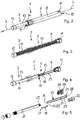
- figure 1 shows a piece of furniture 1 with a body 2 and a flap 4 (furniture part) attached to the body 2 so that it can pivot about a horizontal axis 3 .
- the flap 4 is pivoted from a closed position, in which it is arranged substantially vertically, to an upwardly pivoted position figure 1 shown open position movable.
- Lid adjusters can be used for this purpose.
- the body 2 has an ejection device 5 on each of the lower right and left corners, which is used to move the flap 4 from the closed position into a position that is pushed forward. For this, click on the flap 4 pressed against the flap 4 against the ejection directions A of the ejection devices. As a result, the ejection devices 5 are unlocked and push the flap forwards away from the body 2 in the ejection direction A.
- the ejection devices 5 each have a housing 6 which can be embedded in a bore in a side wall of the body 2, for example. Furthermore, the ejection devices 5 each have a plunger 7 which can be adjusted in the ejection direction A and opposite to the ejection direction A relative to the housing 6 .
- FIG. 12 shows a perspective view of one of the ejection devices 5 according to FIG figure 1 .
- the housing 6 has a substantially cylindrical, tubular housing sleeve 8 which has an opening 9 from which the plunger 7 protrudes. Furthermore, the housing sleeve 8 has an opening 10 which faces away from the opening 9 and from which the plunger 7 protrudes and which is closed by a plug element 11 .
- the plug element 11 here forms a bottom of the housing 6.
- the plunger 7 can be adjusted in the direction of the ejection direction A and counter to the ejection direction A along a longitudinal axis L of the ejection device 5 relative to the housing 6.
- the plunger 7 has a pressure piece 12 which merges into a sleeve 13 in the direction of the housing 6 .
- the sleeve 13 is adjustably guided in the housing sleeve 8 .
- the housing 6 also has a collar 14 in the area of the opening 9, which projects radially outwards from the housing sleeve 8 and serves as a stop. If the housing sleeve 8 in a bore of a side wall of the body 2 according figure 1 is pushed in, the collar 14 ensures that the housing 6 is not inserted too deeply into the bore of the body 2 .
- FIG figure 3 shows the ejection device 5 according to FIG figure 2 ,
- the housing sleeve 8 and the sleeve 13 are only indicated. It can be seen that in the housing sleeve 8 and in A helical spring 15 is arranged on the sleeve 13 of the tappet 7 and is supported axially on the one hand against the plug element 11 and on the other hand against the tappet 7 .
- the helical spring 15 is arranged pretensioned in such a way that it pushes the plunger 7 into the in figure 2 shown extended position applied.
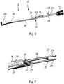
- figure 4 shows the ejection device 5 according to FIG figure 3 , in addition to which the coil spring 15 is omitted. It can be seen that inside the sleeve 13 of the ram 7 there is a mandrel 16 which is arranged coaxially to the longitudinal axis L and adjoins the pressure piece 12 . The mandrel 16 extends in the direction of the plug element 11. The coil spring 15 according to figure 3 is mounted on the mandrel 16.
- a control lever 18 is pivotably connected to the mandrel 16 about an axis which runs perpendicular to the longitudinal axis L.
- the control lever 18 has a coupling element 19 which is provided with an in figure 5 heart-shaped cam 20 shown in the plug element 11 interacts.
- the control lever 18 is made of a wire which runs substantially parallel to the longitudinal axis L and has a first end 21 and a second end 22 .
- the first end 21 and the second end 22 are bent in a direction perpendicular to the longitudinal axis L.
- the first end 21 of the control lever 18 sits pivotably in an opening in the mandrel 16.
- the second end 22 forms the coupling element 19.
- a stop element 23 is also provided.
- the stop element 23 is made of wire and has two legs 24, 25 arranged parallel to one another, which are connected to one another in a U-shape via a connecting section 26. At the ends facing away from the connecting section 26, the legs 25, 26 each have fastening sections 27, 28, which are bent perpendicularly to the longitudinal axis L. The fastening sections 27, 28 are secured in corresponding bores of the plug element 11.
- a stop 29 which is designed as an extension running transversely to the longitudinal axis L and protrudes between the legs 24 , 25 of the stop element 23 .
- the stop 29 moves between the legs 25, 26 in the axial direction.
- the stop 29 abuts axially against the connecting section 26 of the stop element 23, so that the ram 7 cannot be extended any further in the ejection direction A.
- figure 6 shows the components of the ejection device 5 according to FIG figure 4 , wherein the ejection device 5 is shown rotated by 90° about the longitudinal axis L.
- figure 7 shows the components of the ejection device 5 according to FIG figure 6 in an enlarged view in the area of the stop 19 and the control lever 18.
- the mandrel 16 has a slot 30 which extends in the direction of the pressure piece 12 but ends in front of the pressure piece 12 .
- the slot 30 completely penetrates the mandrel 16 in the radial direction.
- the stop element 23 in particular the connecting section 26 of the stop element 23 , is guided in the slot 30 .
- the stop 29 extends in the radial direction between the two legs 24, 25 of the stop element 23, so that the stop 29 is supported axially against the connecting section 26 in the extended position of the ram 7 and the ram 7 cannot be extended any further.
- the control lever 18 sits with its first end 21 in the radial direction in an opening 31 of the mandrel 16, the opening 31 extending in the radial direction transversely to the slot 30.
- the control lever 18 is secured in the opening 31 by the stop 29 in such a way that it cannot be accidentally removed from the opening 31 .
- the stop 29 allows the control lever 18 to pivot about an axis radial to the longitudinal axis L and parallel to the first end 21 .
- figure 8 shows a view of the plunger 7 according to FIG figure 2 in the direction of the ejection direction including the housing 6 and including the stop element 23.
- the coil spring 15 is arranged in an annular gap 32 between the mandrel 16 and the sleeve 13 of the plunger 7.
- the outside diameter of the mandrel 16 is closely matched to the inner diameter of the helical spring 15, so that the helical spring 15 is guided securely on the mandrel 16.
- the annular gap 32 between the sleeve 13 and the helical spring 15 is not filled.
- the sleeve 13 has guide projections 33 in the form of ribs extending parallel to the longitudinal axis L, which extend inward from the Sleeve 13 protrude.
- the shaped spring 15 is supported radially outwards by these guide projections 33 .
- a guide sleeve 34 is arranged in the housing 6 , which is connected to the plug element 11 and protrudes axially from the plug element 11 in the direction of the plunger 7 .
- the support sleeve 34 according to figure 9 has a cylindrical, tubular section 35 with which, as will be shown later, the support sleeve 34 is attached to the plug element 11 .
- the support sleeve 34 On the side facing away from the plug element 11, the support sleeve 34 has three wall sections 36 extending in the longitudinal direction, which form slots 37 between them, which also extend parallel to the longitudinal axis L.
- the sleeve 13 of the tappet 7 has three rib-like guide projections 33 distributed over the circumference.
- three slots 37 distributed over the circumference are formed in the support sleeve 34 .
- a different number of guide projections 33 and slots 37 can also be provided.
- the support sleeve 34 enters the radial gap 32 of the plunger 7, with the guide projections 33 entering and being guided in the slots 37, so that the plunger 7 is prevented from twisting in relation to the housing 6.
- the support sleeve 34 surrounds the helical spring 15 so that it is also supported radially outwards by the support sleeve 34 .
- the Figures 10 to 13 show the ejection device 5 in different positions in longitudinal section.
- the figure 10 shows the plunger 7 in the extended position.
- the Figures 11 and 13 show the plunger 7 in the retracted position and the figure 12 shows the ram in an intermediate position.
- the plunger 7 Starting from the extended position according to figure 10 can the plunger 7 against the extension A in the retracted position according to figure 11 to press.
- the control lever 18 interacts with the cam 20 in this case.
- the plunger 7 When the plunger 7 is relieved, the plunger moves to the intermediate position according to FIG figure 12 pressed, wherein the control lever 18 holds the plunger 17 against the spring force of the coil spring 15 in the intermediate position. If the plunger 7 is pushed in again against the ejection direction A up to the retracted position according to FIG figure 13 the control lever 18 is released so that the plunger 7 returns to the extended position in the ejection direction A according to FIG figure 10 is moved.
- the plug element 11 is composed of a first half 38 and a second half 39 .
- the cam 20 is introduced.
- the cam 20 is incorporated into an inner surface of the first half 38 .
- the inner surface of the second half 39 has a recess which allows the control lever 18 to pivot.
- the cam 20, which in figure 14 is shown enlarged, is designed in the form of a so-called heart curve and has a guide section 40 which opens into an opening 41 of the control cam 20 .
- the cam 20 When moving the ram 7 from the in figure 10 illustrated extended position towards the retracted position according to figure 11 dips the first end 21 of the control lever 18, which forms the coupling element 19, through the opening 41 in the guide portion 40 of the cam 20 a.
- the coupling element 19 abuts against a guide surface 42 of the cam 20 and directs the coupling element 19 into an insertion branch 43, which leads to a detent trough 44 of the cam.
- the coupling element 19 is deflected in such a way that when the ram 7 is released from the pushed-in position, the ram dips into the latching recess 44 and there against further extension in the intermediate position according to FIG figure 12 is secured.
- a second guide surface 45 is used for this purpose figure 13 pushes the coupling element 19 against a third guide surface 46 and is in the direction of an ejection branch 47 of Cam 20 deflected.
- the support sleeve 34 can be seen, which is connected to the plug element 11 and surrounds the coil spring 15.
Landscapes
- Closing And Opening Devices For Wings, And Checks For Wings (AREA)
Priority Applications (3)
| Application Number | Priority Date | Filing Date | Title |
|---|---|---|---|
| EP17180219.2A EP3425151B1 (de) | 2017-07-07 | 2017-07-07 | Ausstossvorrichtung für ein möbelteil |
| PL17180219.2T PL3425151T3 (pl) | 2017-07-07 | 2017-07-07 | Urządzenie wypychające do części mebla |
| ES17180219T ES2929184T3 (es) | 2017-07-07 | 2017-07-07 | Dispositivo de expulsión de un mueble |
Applications Claiming Priority (1)
| Application Number | Priority Date | Filing Date | Title |
|---|---|---|---|
| EP17180219.2A EP3425151B1 (de) | 2017-07-07 | 2017-07-07 | Ausstossvorrichtung für ein möbelteil |
Publications (2)
| Publication Number | Publication Date |
|---|---|
| EP3425151A1 EP3425151A1 (de) | 2019-01-09 |
| EP3425151B1 true EP3425151B1 (de) | 2022-08-31 |
Family
ID=59313036
Family Applications (1)
| Application Number | Title | Priority Date | Filing Date |
|---|---|---|---|
| EP17180219.2A Active EP3425151B1 (de) | 2017-07-07 | 2017-07-07 | Ausstossvorrichtung für ein möbelteil |
Country Status (3)
| Country | Link |
|---|---|
| EP (1) | EP3425151B1 (pl) |
| ES (1) | ES2929184T3 (pl) |
| PL (1) | PL3425151T3 (pl) |
Cited By (1)
| Publication number | Priority date | Publication date | Assignee | Title |
|---|---|---|---|---|
| EP4629857A4 (en) * | 2022-12-06 | 2026-01-07 | Samet Kalip Ve Madeni Esya San Ve Tic A S | PUSH-OPEN MECHANISM FOR FURNITURE |
Families Citing this family (1)
| Publication number | Priority date | Publication date | Assignee | Title |
|---|---|---|---|---|
| IT202200017889A1 (it) * | 2022-08-31 | 2024-03-02 | Effegi Brevetti Srl | Dispositivo per l’apertura a scatto di ante di mobili |
Family Cites Families (2)
| Publication number | Priority date | Publication date | Assignee | Title |
|---|---|---|---|---|
| DE202004019238U1 (de) * | 2004-12-10 | 2005-02-17 | MEPLA-WERKE LAUTENSCHLäGER GMBH & CO. KG | Möbel-Scharnier mit Schließ- und Öffnungsvorrichtung |
| DE202013102035U1 (de) | 2013-05-10 | 2013-05-21 | Huwil Kft | Klappenmöbel mit zwei Push-to-open-Beschlägen |
-
2017
- 2017-07-07 EP EP17180219.2A patent/EP3425151B1/de active Active
- 2017-07-07 PL PL17180219.2T patent/PL3425151T3/pl unknown
- 2017-07-07 ES ES17180219T patent/ES2929184T3/es active Active
Cited By (1)
| Publication number | Priority date | Publication date | Assignee | Title |
|---|---|---|---|---|
| EP4629857A4 (en) * | 2022-12-06 | 2026-01-07 | Samet Kalip Ve Madeni Esya San Ve Tic A S | PUSH-OPEN MECHANISM FOR FURNITURE |
Also Published As
| Publication number | Publication date |
|---|---|
| PL3425151T3 (pl) | 2023-02-13 |
| ES2929184T3 (es) | 2022-11-25 |
| EP3425151A1 (de) | 2019-01-09 |
Similar Documents
| Publication | Publication Date | Title |
|---|---|---|
| EP2286048B1 (de) | Dämpfungseinrichtung für möbeltüren | |
| EP2661195B1 (de) | VERRIEGELBARE AUSSTOßVORRICHTUNG MIT ÜBERLASTMECHANISMUS | |
| EP3238568B1 (de) | Schubladensystem | |
| EP3141153B1 (de) | Vorrichtung zum bewegen eines bewegbaren möbelteils in eine öffnungsrichtung in bezug zu einem möbelkorpus eines möbels | |
| DE102017107461A1 (de) | Bewegungsanordnung | |
| EP2175093A2 (de) | Rastbolzen mit Verriegelungsmechanik | |
| EP1907657B1 (de) | Dämpfungselement | |
| EP2801688B1 (de) | Klappenmöbel mit zwei push-to-open-beschlägen | |
| EP3518707B1 (de) | Einzugsvorrichtung für einen schubladenauszug | |
| EP3181013B1 (de) | Auswerferanordnung für ein bewegbares möbelteil | |
| EP3625415B1 (de) | Klappenlager mit einer einstellhilfe | |
| EP3098461A1 (de) | Rastbolzen | |
| WO2010112522A1 (de) | Einzugvorrichtung | |
| EP3153646A1 (de) | Fenster- und/oder türsicherung | |
| EP2713822B1 (de) | Schiebeanordnung | |
| EP3425151B1 (de) | Ausstossvorrichtung für ein möbelteil | |
| EP3142516B1 (de) | Einzugsvorrichtung für möbel | |
| EP2560520B1 (de) | AUSSTOßER ZUM AUSSTOßEN EINES BEWEGBAREN MÖBELTEILS | |
| DE102009020994B4 (de) | Einzugvorrichtung | |
| EP3034728A1 (de) | Öffnungsbegrenzereinrichtung | |
| EP3625416A1 (de) | Federpaket für einen klappenhalter | |
| EP2744963B1 (de) | Vorrichtung zum einziehen eines bewegbaren möbelteils in eine mittelstellung | |
| EP4077843B1 (de) | Führungsanordnung zur führung wenigstens eines bewegbaren möbelteils | |
| EP3563724B1 (de) | Vorrichtung zum schliessen eines bewegbaren möbelteils | |
| DE10024113B4 (de) | Klammerformvorrichtung |
Legal Events
| Date | Code | Title | Description |
|---|---|---|---|
| PUAI | Public reference made under article 153(3) epc to a published international application that has entered the european phase |
Free format text: ORIGINAL CODE: 0009012 |
|
| STAA | Information on the status of an ep patent application or granted ep patent |
Free format text: STATUS: THE APPLICATION HAS BEEN PUBLISHED |
|
| AK | Designated contracting states |
Kind code of ref document: A1 Designated state(s): AL AT BE BG CH CY CZ DE DK EE ES FI FR GB GR HR HU IE IS IT LI LT LU LV MC MK MT NL NO PL PT RO RS SE SI SK SM TR |
|
| AX | Request for extension of the european patent |
Extension state: BA ME |
|
| STAA | Information on the status of an ep patent application or granted ep patent |
Free format text: STATUS: REQUEST FOR EXAMINATION WAS MADE |
|
| 17P | Request for examination filed |
Effective date: 20190607 |
|
| RBV | Designated contracting states (corrected) |
Designated state(s): AL AT BE BG CH CY CZ DE DK EE ES FI FR GB GR HR HU IE IS IT LI LT LU LV MC MK MT NL NO PL PT RO RS SE SI SK SM TR |
|
| GRAP | Despatch of communication of intention to grant a patent |
Free format text: ORIGINAL CODE: EPIDOSNIGR1 |
|
| STAA | Information on the status of an ep patent application or granted ep patent |
Free format text: STATUS: GRANT OF PATENT IS INTENDED |
|
| INTG | Intention to grant announced |
Effective date: 20220608 |
|
| GRAS | Grant fee paid |
Free format text: ORIGINAL CODE: EPIDOSNIGR3 |
|
| GRAA | (expected) grant |
Free format text: ORIGINAL CODE: 0009210 |
|
| STAA | Information on the status of an ep patent application or granted ep patent |
Free format text: STATUS: THE PATENT HAS BEEN GRANTED |
|
| AK | Designated contracting states |
Kind code of ref document: B1 Designated state(s): AL AT BE BG CH CY CZ DE DK EE ES FI FR GB GR HR HU IE IS IT LI LT LU LV MC MK MT NL NO PL PT RO RS SE SI SK SM TR |
|
| REG | Reference to a national code |
Ref country code: CH Ref legal event code: EP Ref country code: GB Ref legal event code: FG4D Free format text: NOT ENGLISH |
|
| REG | Reference to a national code |
Ref country code: AT Ref legal event code: REF Ref document number: 1515400 Country of ref document: AT Kind code of ref document: T Effective date: 20220915 Ref country code: DE Ref legal event code: R096 Ref document number: 502017013702 Country of ref document: DE |
|
| REG | Reference to a national code |
Ref country code: IE Ref legal event code: FG4D Free format text: LANGUAGE OF EP DOCUMENT: GERMAN |
|
| REG | Reference to a national code |
Ref country code: SE Ref legal event code: TRGR |
|
| REG | Reference to a national code |
Ref country code: ES Ref legal event code: FG2A Ref document number: 2929184 Country of ref document: ES Kind code of ref document: T3 Effective date: 20221125 |
|
| REG | Reference to a national code |
Ref country code: LT Ref legal event code: MG9D |
|
| REG | Reference to a national code |
Ref country code: NL Ref legal event code: MP Effective date: 20220831 |
|
| PG25 | Lapsed in a contracting state [announced via postgrant information from national office to epo] |
Ref country code: RS Free format text: LAPSE BECAUSE OF FAILURE TO SUBMIT A TRANSLATION OF THE DESCRIPTION OR TO PAY THE FEE WITHIN THE PRESCRIBED TIME-LIMIT Effective date: 20220831 Ref country code: NO Free format text: LAPSE BECAUSE OF FAILURE TO SUBMIT A TRANSLATION OF THE DESCRIPTION OR TO PAY THE FEE WITHIN THE PRESCRIBED TIME-LIMIT Effective date: 20221130 Ref country code: LV Free format text: LAPSE BECAUSE OF FAILURE TO SUBMIT A TRANSLATION OF THE DESCRIPTION OR TO PAY THE FEE WITHIN THE PRESCRIBED TIME-LIMIT Effective date: 20220831 Ref country code: LT Free format text: LAPSE BECAUSE OF FAILURE TO SUBMIT A TRANSLATION OF THE DESCRIPTION OR TO PAY THE FEE WITHIN THE PRESCRIBED TIME-LIMIT Effective date: 20220831 Ref country code: FI Free format text: LAPSE BECAUSE OF FAILURE TO SUBMIT A TRANSLATION OF THE DESCRIPTION OR TO PAY THE FEE WITHIN THE PRESCRIBED TIME-LIMIT Effective date: 20220831 |
|
| PG25 | Lapsed in a contracting state [announced via postgrant information from national office to epo] |
Ref country code: IS Free format text: LAPSE BECAUSE OF FAILURE TO SUBMIT A TRANSLATION OF THE DESCRIPTION OR TO PAY THE FEE WITHIN THE PRESCRIBED TIME-LIMIT Effective date: 20221231 Ref country code: HR Free format text: LAPSE BECAUSE OF FAILURE TO SUBMIT A TRANSLATION OF THE DESCRIPTION OR TO PAY THE FEE WITHIN THE PRESCRIBED TIME-LIMIT Effective date: 20220831 Ref country code: GR Free format text: LAPSE BECAUSE OF FAILURE TO SUBMIT A TRANSLATION OF THE DESCRIPTION OR TO PAY THE FEE WITHIN THE PRESCRIBED TIME-LIMIT Effective date: 20221201 |
|
| PG25 | Lapsed in a contracting state [announced via postgrant information from national office to epo] |
Ref country code: SM Free format text: LAPSE BECAUSE OF FAILURE TO SUBMIT A TRANSLATION OF THE DESCRIPTION OR TO PAY THE FEE WITHIN THE PRESCRIBED TIME-LIMIT Effective date: 20220831 Ref country code: RO Free format text: LAPSE BECAUSE OF FAILURE TO SUBMIT A TRANSLATION OF THE DESCRIPTION OR TO PAY THE FEE WITHIN THE PRESCRIBED TIME-LIMIT Effective date: 20220831 Ref country code: PT Free format text: LAPSE BECAUSE OF FAILURE TO SUBMIT A TRANSLATION OF THE DESCRIPTION OR TO PAY THE FEE WITHIN THE PRESCRIBED TIME-LIMIT Effective date: 20230102 Ref country code: DK Free format text: LAPSE BECAUSE OF FAILURE TO SUBMIT A TRANSLATION OF THE DESCRIPTION OR TO PAY THE FEE WITHIN THE PRESCRIBED TIME-LIMIT Effective date: 20220831 Ref country code: CZ Free format text: LAPSE BECAUSE OF FAILURE TO SUBMIT A TRANSLATION OF THE DESCRIPTION OR TO PAY THE FEE WITHIN THE PRESCRIBED TIME-LIMIT Effective date: 20220831 |
|
| PG25 | Lapsed in a contracting state [announced via postgrant information from national office to epo] |
Ref country code: SK Free format text: LAPSE BECAUSE OF FAILURE TO SUBMIT A TRANSLATION OF THE DESCRIPTION OR TO PAY THE FEE WITHIN THE PRESCRIBED TIME-LIMIT Effective date: 20220831 Ref country code: EE Free format text: LAPSE BECAUSE OF FAILURE TO SUBMIT A TRANSLATION OF THE DESCRIPTION OR TO PAY THE FEE WITHIN THE PRESCRIBED TIME-LIMIT Effective date: 20220831 |
|
| REG | Reference to a national code |
Ref country code: DE Ref legal event code: R097 Ref document number: 502017013702 Country of ref document: DE |
|
| P01 | Opt-out of the competence of the unified patent court (upc) registered |
Effective date: 20230329 |
|
| PG25 | Lapsed in a contracting state [announced via postgrant information from national office to epo] |
Ref country code: NL Free format text: LAPSE BECAUSE OF FAILURE TO SUBMIT A TRANSLATION OF THE DESCRIPTION OR TO PAY THE FEE WITHIN THE PRESCRIBED TIME-LIMIT Effective date: 20220831 Ref country code: AL Free format text: LAPSE BECAUSE OF FAILURE TO SUBMIT A TRANSLATION OF THE DESCRIPTION OR TO PAY THE FEE WITHIN THE PRESCRIBED TIME-LIMIT Effective date: 20220831 |
|
| PLBE | No opposition filed within time limit |
Free format text: ORIGINAL CODE: 0009261 |
|
| STAA | Information on the status of an ep patent application or granted ep patent |
Free format text: STATUS: NO OPPOSITION FILED WITHIN TIME LIMIT |
|
| 26N | No opposition filed |
Effective date: 20230601 |
|
| PG25 | Lapsed in a contracting state [announced via postgrant information from national office to epo] |
Ref country code: SI Free format text: LAPSE BECAUSE OF FAILURE TO SUBMIT A TRANSLATION OF THE DESCRIPTION OR TO PAY THE FEE WITHIN THE PRESCRIBED TIME-LIMIT Effective date: 20220831 |
|
| PGFP | Annual fee paid to national office [announced via postgrant information from national office to epo] |
Ref country code: SE Payment date: 20230724 Year of fee payment: 7 |
|
| PG25 | Lapsed in a contracting state [announced via postgrant information from national office to epo] |
Ref country code: MC Free format text: LAPSE BECAUSE OF FAILURE TO SUBMIT A TRANSLATION OF THE DESCRIPTION OR TO PAY THE FEE WITHIN THE PRESCRIBED TIME-LIMIT Effective date: 20220831 |
|
| PG25 | Lapsed in a contracting state [announced via postgrant information from national office to epo] |
Ref country code: MC Free format text: LAPSE BECAUSE OF FAILURE TO SUBMIT A TRANSLATION OF THE DESCRIPTION OR TO PAY THE FEE WITHIN THE PRESCRIBED TIME-LIMIT Effective date: 20220831 |
|
| REG | Reference to a national code |
Ref country code: CH Ref legal event code: PL |
|
| REG | Reference to a national code |
Ref country code: BE Ref legal event code: MM Effective date: 20230731 |
|
| PG25 | Lapsed in a contracting state [announced via postgrant information from national office to epo] |
Ref country code: LU Free format text: LAPSE BECAUSE OF NON-PAYMENT OF DUE FEES Effective date: 20230707 |
|
| PG25 | Lapsed in a contracting state [announced via postgrant information from national office to epo] |
Ref country code: LU Free format text: LAPSE BECAUSE OF NON-PAYMENT OF DUE FEES Effective date: 20230707 |
|
| REG | Reference to a national code |
Ref country code: IE Ref legal event code: MM4A |
|
| PG25 | Lapsed in a contracting state [announced via postgrant information from national office to epo] |
Ref country code: CH Free format text: LAPSE BECAUSE OF NON-PAYMENT OF DUE FEES Effective date: 20230731 |
|
| PG25 | Lapsed in a contracting state [announced via postgrant information from national office to epo] |
Ref country code: BE Free format text: LAPSE BECAUSE OF NON-PAYMENT OF DUE FEES Effective date: 20230731 |
|
| PG25 | Lapsed in a contracting state [announced via postgrant information from national office to epo] |
Ref country code: IE Free format text: LAPSE BECAUSE OF NON-PAYMENT OF DUE FEES Effective date: 20230707 |
|
| PG25 | Lapsed in a contracting state [announced via postgrant information from national office to epo] |
Ref country code: IE Free format text: LAPSE BECAUSE OF NON-PAYMENT OF DUE FEES Effective date: 20230707 |
|
| REG | Reference to a national code |
Ref country code: AT Ref legal event code: MM01 Ref document number: 1515400 Country of ref document: AT Kind code of ref document: T Effective date: 20230707 |
|
| PG25 | Lapsed in a contracting state [announced via postgrant information from national office to epo] |
Ref country code: AT Free format text: LAPSE BECAUSE OF NON-PAYMENT OF DUE FEES Effective date: 20230707 |
|
| PG25 | Lapsed in a contracting state [announced via postgrant information from national office to epo] |
Ref country code: AT Free format text: LAPSE BECAUSE OF NON-PAYMENT OF DUE FEES Effective date: 20230707 |
|
| PG25 | Lapsed in a contracting state [announced via postgrant information from national office to epo] |
Ref country code: BG Free format text: LAPSE BECAUSE OF FAILURE TO SUBMIT A TRANSLATION OF THE DESCRIPTION OR TO PAY THE FEE WITHIN THE PRESCRIBED TIME-LIMIT Effective date: 20220831 |
|
| PG25 | Lapsed in a contracting state [announced via postgrant information from national office to epo] |
Ref country code: BG Free format text: LAPSE BECAUSE OF FAILURE TO SUBMIT A TRANSLATION OF THE DESCRIPTION OR TO PAY THE FEE WITHIN THE PRESCRIBED TIME-LIMIT Effective date: 20220831 |
|
| REG | Reference to a national code |
Ref country code: SE Ref legal event code: EUG |
|
| PGFP | Annual fee paid to national office [announced via postgrant information from national office to epo] |
Ref country code: PL Payment date: 20250624 Year of fee payment: 9 |
|
| PG25 | Lapsed in a contracting state [announced via postgrant information from national office to epo] |
Ref country code: CY Free format text: LAPSE BECAUSE OF FAILURE TO SUBMIT A TRANSLATION OF THE DESCRIPTION OR TO PAY THE FEE WITHIN THE PRESCRIBED TIME-LIMIT; INVALID AB INITIO Effective date: 20170707 |
|
| PG25 | Lapsed in a contracting state [announced via postgrant information from national office to epo] |
Ref country code: HU Free format text: LAPSE BECAUSE OF FAILURE TO SUBMIT A TRANSLATION OF THE DESCRIPTION OR TO PAY THE FEE WITHIN THE PRESCRIBED TIME-LIMIT; INVALID AB INITIO Effective date: 20170707 |
|
| PGFP | Annual fee paid to national office [announced via postgrant information from national office to epo] |
Ref country code: ES Payment date: 20250819 Year of fee payment: 9 |
|
| PGFP | Annual fee paid to national office [announced via postgrant information from national office to epo] |
Ref country code: DE Payment date: 20250722 Year of fee payment: 9 |
|
| PG25 | Lapsed in a contracting state [announced via postgrant information from national office to epo] |
Ref country code: SE Free format text: LAPSE BECAUSE OF NON-PAYMENT OF DUE FEES Effective date: 20240708 |
|
| PGFP | Annual fee paid to national office [announced via postgrant information from national office to epo] |
Ref country code: TR Payment date: 20250702 Year of fee payment: 9 Ref country code: IT Payment date: 20250731 Year of fee payment: 9 |
|
| PGFP | Annual fee paid to national office [announced via postgrant information from national office to epo] |
Ref country code: GB Payment date: 20250724 Year of fee payment: 9 |
|
| PGFP | Annual fee paid to national office [announced via postgrant information from national office to epo] |
Ref country code: FR Payment date: 20250723 Year of fee payment: 9 |