EP3425151B1 - Ausstossvorrichtung für ein möbelteil - Google Patents
Ausstossvorrichtung für ein möbelteil Download PDFInfo
- Publication number
- EP3425151B1 EP3425151B1 EP17180219.2A EP17180219A EP3425151B1 EP 3425151 B1 EP3425151 B1 EP 3425151B1 EP 17180219 A EP17180219 A EP 17180219A EP 3425151 B1 EP3425151 B1 EP 3425151B1
- Authority
- EP
- European Patent Office
- Prior art keywords
- housing
- sleeve
- plunger
- ejecting device
- base
- Prior art date
- Legal status (The legal status is an assumption and is not a legal conclusion. Google has not performed a legal analysis and makes no representation as to the accuracy of the status listed.)
- Active
Links
Images



Classifications
-
- E—FIXED CONSTRUCTIONS
- E05—LOCKS; KEYS; WINDOW OR DOOR FITTINGS; SAFES
- E05F—DEVICES FOR MOVING WINGS INTO OPEN OR CLOSED POSITION; CHECKS FOR WINGS; WING FITTINGS NOT OTHERWISE PROVIDED FOR, CONCERNED WITH THE FUNCTIONING OF THE WING
- E05F1/00—Closers or openers for wings, not otherwise provided for in this subclass
- E05F1/08—Closers or openers for wings, not otherwise provided for in this subclass spring-actuated, e.g. for horizontally sliding wings
- E05F1/10—Closers or openers for wings, not otherwise provided for in this subclass spring-actuated, e.g. for horizontally sliding wings for swinging wings, e.g. counterbalance
- E05F1/1041—Closers or openers for wings, not otherwise provided for in this subclass spring-actuated, e.g. for horizontally sliding wings for swinging wings, e.g. counterbalance with a coil spring perpendicular to the pivot axis
- E05F1/105—Closers or openers for wings, not otherwise provided for in this subclass spring-actuated, e.g. for horizontally sliding wings for swinging wings, e.g. counterbalance with a coil spring perpendicular to the pivot axis with a compression spring
-
- E—FIXED CONSTRUCTIONS
- E05—LOCKS; KEYS; WINDOW OR DOOR FITTINGS; SAFES
- E05F—DEVICES FOR MOVING WINGS INTO OPEN OR CLOSED POSITION; CHECKS FOR WINGS; WING FITTINGS NOT OTHERWISE PROVIDED FOR, CONCERNED WITH THE FUNCTIONING OF THE WING
- E05F5/00—Braking devices, e.g. checks; Stops; Buffers
- E05F5/02—Braking devices, e.g. checks; Stops; Buffers specially for preventing the slamming of swinging wings during final closing movement, e.g. jamb stops
-
- E—FIXED CONSTRUCTIONS
- E05—LOCKS; KEYS; WINDOW OR DOOR FITTINGS; SAFES
- E05F—DEVICES FOR MOVING WINGS INTO OPEN OR CLOSED POSITION; CHECKS FOR WINGS; WING FITTINGS NOT OTHERWISE PROVIDED FOR, CONCERNED WITH THE FUNCTIONING OF THE WING
- E05F5/00—Braking devices, e.g. checks; Stops; Buffers
- E05F5/06—Buffers or stops limiting opening of swinging wings, e.g. floor or wall stops
- E05F5/08—Buffers or stops limiting opening of swinging wings, e.g. floor or wall stops with springs
-
- E—FIXED CONSTRUCTIONS
- E05—LOCKS; KEYS; WINDOW OR DOOR FITTINGS; SAFES
- E05Y—INDEXING SCHEME ASSOCIATED WITH SUBCLASSES E05D AND E05F, RELATING TO CONSTRUCTION ELEMENTS, ELECTRIC CONTROL, POWER SUPPLY, POWER SIGNAL OR TRANSMISSION, USER INTERFACES, MOUNTING OR COUPLING, DETAILS, ACCESSORIES, AUXILIARY OPERATIONS NOT OTHERWISE PROVIDED FOR, APPLICATION THEREOF
- E05Y2900/00—Application of doors, windows, wings or fittings thereof
- E05Y2900/20—Application of doors, windows, wings or fittings thereof for furniture, e.g. cabinets
Definitions
- the invention relates to an ejection device according to the preamble of claim 1.
- Such an ejector is from DE 20 2013 102 035 U1 known.
- a so-called push-to-open fitting is described there. This is used in a piece of furniture with a furniture part mounted on a furniture body such that it can be pivoted, in particular pivoted upwards, and with two push-to-open fittings arranged on both sides of the furniture part on the furniture body for ejecting the furniture part from its closed position into an open position.
- the push-to-open fittings each have a slidably guided ram (ejector ram) that is pretensioned by a spring in the ejection direction of the furniture part, an ejection guide with a heart curve and a control lever articulated on the ejector ram, which is guided in the ejection guide and counteracts the ejector ram the ejection force of the spring latches in a detent recess of the heart curve.
- the ejector plunger rests against an inside end stop of the sleeve of the housing.
- Such ejection devices are attached to a furniture body in different ways.
- One of the possibilities is to provide a hole in a side wall into which the ejection device is inserted.
- the device has a mechanism that allows the door leaf in the closed position to be given a movement in the opening direction by means of additional pressure exerted in the direction of the interior of the body , so that the back of the door leaf can then be gripped in the edge area and the door leaf can be opened - even without the presence of a handle fitting.
- the mechanism has a housing in which a pressure piece is arranged to be longitudinally displaceable. The pressure piece is loaded with force in the direction of an extended position via a spring, which is supported against the housing via an adjusting screw.
- a heart-shaped control curve is formed, which is engaged by a lever that is pivotably connected to the adjusting screw.
- the object of the present invention is to provide an ejection device with the smallest possible external diameter.
- the stop element is thus located within the helical spring that sits on the mandrel, so that an extremely compact design is guaranteed. It is not necessary for the sleeve of the tappet to have, for example, an outwardly facing collar which abuts axially against a corresponding inwardly facing collar of the housing. Thus, the sleeve and housing can be made thinner, resulting in a reduced outer diameter.
- the tappet has a control lever with a coupling element, the coupling element interacting with a heart-shaped cam in the bottom of the housing at least over part of the axial displacement path of the tappet relative to the housing.
- a mechanism is provided that is similar to a Ballpoint pen mechanism ensures that when the plunger is initially transferred to the retracted position, it remains in an intermediate position between the retracted position and the extended position and, when the plunger is actuated or pressed again to the retracted position, then transferred by the coil spring to the extended position becomes.
- a so-called heart-shaped control curve is used, such as that in FIG DE 20 2013 102 035 U1 is described.
- the stop element can be a wire.
- the wire can have a substantially U-shaped configuration and its free ends can be attached to the bottom of the housing.
- the mandrel can have a stop element which is guided axially between the legs of the U-shaped wire and, in the extended position, abuts against a connecting section between the two legs of the U-shaped wire.
- the bottom may be represented by a plug member seated in a housing sleeve of the housing.
- the housing sleeve can be designed as a cylindrical tube which has two openings facing away from one another.
- the plug element sits in one of the two openings and thus closes the housing sleeve on one side.
- the opening facing away from the plug element is that opening from which the plunger can be moved out.
- the sleeve of the mandrel can have guide projections pointing inwards, against which the helical spring is radially supported.
- the helical spring is supported axially against the plunger on the one hand and against the bottom of the housing on the other hand, so that the helical spring urges the plunger towards the extended position.
- the coil spring is compressed. If there is no radial support, this can lead to the helical spring bulging radially.
- the guide projections are provided.
- the guide projections can be designed as axially extending ribs.
- the housing has a support sleeve which is attached to the bottom of the housing and in which the helical spring is accommodated, the support sleeve having axially extending slots into which the guide projections, when the plunger is axially displaced relative to the housing, immerse
- the helical spring is supported radially on the inside against the support sleeve, so that it cannot bulge radially either in the area of the support sleeve. This ensures that the helical spring is supported in the radial direction over the greatest possible axial area.
- the support sleeve can be accommodated in an axially displaceable manner in the sleeve of the plunger, at least over part of the displacement path of the plunger.
- figure 1 shows a piece of furniture 1 with a body 2 and a flap 4 (furniture part) attached to the body 2 so that it can pivot about a horizontal axis 3 .
- the flap 4 is pivoted from a closed position, in which it is arranged substantially vertically, to an upwardly pivoted position figure 1 shown open position movable.
- Lid adjusters can be used for this purpose.
- the body 2 has an ejection device 5 on each of the lower right and left corners, which is used to move the flap 4 from the closed position into a position that is pushed forward. For this, click on the flap 4 pressed against the flap 4 against the ejection directions A of the ejection devices. As a result, the ejection devices 5 are unlocked and push the flap forwards away from the body 2 in the ejection direction A.
- the ejection devices 5 each have a housing 6 which can be embedded in a bore in a side wall of the body 2, for example. Furthermore, the ejection devices 5 each have a plunger 7 which can be adjusted in the ejection direction A and opposite to the ejection direction A relative to the housing 6 .
- FIG. 12 shows a perspective view of one of the ejection devices 5 according to FIG figure 1 .
- the housing 6 has a substantially cylindrical, tubular housing sleeve 8 which has an opening 9 from which the plunger 7 protrudes. Furthermore, the housing sleeve 8 has an opening 10 which faces away from the opening 9 and from which the plunger 7 protrudes and which is closed by a plug element 11 .
- the plug element 11 here forms a bottom of the housing 6.
- the plunger 7 can be adjusted in the direction of the ejection direction A and counter to the ejection direction A along a longitudinal axis L of the ejection device 5 relative to the housing 6.
- the plunger 7 has a pressure piece 12 which merges into a sleeve 13 in the direction of the housing 6 .
- the sleeve 13 is adjustably guided in the housing sleeve 8 .
- the housing 6 also has a collar 14 in the area of the opening 9, which projects radially outwards from the housing sleeve 8 and serves as a stop. If the housing sleeve 8 in a bore of a side wall of the body 2 according figure 1 is pushed in, the collar 14 ensures that the housing 6 is not inserted too deeply into the bore of the body 2 .
- FIG figure 3 shows the ejection device 5 according to FIG figure 2 ,
- the housing sleeve 8 and the sleeve 13 are only indicated. It can be seen that in the housing sleeve 8 and in A helical spring 15 is arranged on the sleeve 13 of the tappet 7 and is supported axially on the one hand against the plug element 11 and on the other hand against the tappet 7 .
- the helical spring 15 is arranged pretensioned in such a way that it pushes the plunger 7 into the in figure 2 shown extended position applied.
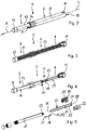
- figure 4 shows the ejection device 5 according to FIG figure 3 , in addition to which the coil spring 15 is omitted. It can be seen that inside the sleeve 13 of the ram 7 there is a mandrel 16 which is arranged coaxially to the longitudinal axis L and adjoins the pressure piece 12 . The mandrel 16 extends in the direction of the plug element 11. The coil spring 15 according to figure 3 is mounted on the mandrel 16.
- a control lever 18 is pivotably connected to the mandrel 16 about an axis which runs perpendicular to the longitudinal axis L.
- the control lever 18 has a coupling element 19 which is provided with an in figure 5 heart-shaped cam 20 shown in the plug element 11 interacts.
- the control lever 18 is made of a wire which runs substantially parallel to the longitudinal axis L and has a first end 21 and a second end 22 .
- the first end 21 and the second end 22 are bent in a direction perpendicular to the longitudinal axis L.
- the first end 21 of the control lever 18 sits pivotably in an opening in the mandrel 16.
- the second end 22 forms the coupling element 19.
- a stop element 23 is also provided.
- the stop element 23 is made of wire and has two legs 24, 25 arranged parallel to one another, which are connected to one another in a U-shape via a connecting section 26. At the ends facing away from the connecting section 26, the legs 25, 26 each have fastening sections 27, 28, which are bent perpendicularly to the longitudinal axis L. The fastening sections 27, 28 are secured in corresponding bores of the plug element 11.
- a stop 29 which is designed as an extension running transversely to the longitudinal axis L and protrudes between the legs 24 , 25 of the stop element 23 .
- the stop 29 moves between the legs 25, 26 in the axial direction.
- the stop 29 abuts axially against the connecting section 26 of the stop element 23, so that the ram 7 cannot be extended any further in the ejection direction A.
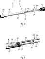
- figure 6 shows the components of the ejection device 5 according to FIG figure 4 , wherein the ejection device 5 is shown rotated by 90° about the longitudinal axis L.
- figure 7 shows the components of the ejection device 5 according to FIG figure 6 in an enlarged view in the area of the stop 19 and the control lever 18.
- the mandrel 16 has a slot 30 which extends in the direction of the pressure piece 12 but ends in front of the pressure piece 12 .
- the slot 30 completely penetrates the mandrel 16 in the radial direction.
- the stop element 23 in particular the connecting section 26 of the stop element 23 , is guided in the slot 30 .
- the stop 29 extends in the radial direction between the two legs 24, 25 of the stop element 23, so that the stop 29 is supported axially against the connecting section 26 in the extended position of the ram 7 and the ram 7 cannot be extended any further.
- the control lever 18 sits with its first end 21 in the radial direction in an opening 31 of the mandrel 16, the opening 31 extending in the radial direction transversely to the slot 30.
- the control lever 18 is secured in the opening 31 by the stop 29 in such a way that it cannot be accidentally removed from the opening 31 .
- the stop 29 allows the control lever 18 to pivot about an axis radial to the longitudinal axis L and parallel to the first end 21 .
- figure 8 shows a view of the plunger 7 according to FIG figure 2 in the direction of the ejection direction including the housing 6 and including the stop element 23.
- the coil spring 15 is arranged in an annular gap 32 between the mandrel 16 and the sleeve 13 of the plunger 7.
- the outside diameter of the mandrel 16 is closely matched to the inner diameter of the helical spring 15, so that the helical spring 15 is guided securely on the mandrel 16.
- the annular gap 32 between the sleeve 13 and the helical spring 15 is not filled.
- the sleeve 13 has guide projections 33 in the form of ribs extending parallel to the longitudinal axis L, which extend inward from the Sleeve 13 protrude.
- the shaped spring 15 is supported radially outwards by these guide projections 33 .
- a guide sleeve 34 is arranged in the housing 6 , which is connected to the plug element 11 and protrudes axially from the plug element 11 in the direction of the plunger 7 .
- the support sleeve 34 according to figure 9 has a cylindrical, tubular section 35 with which, as will be shown later, the support sleeve 34 is attached to the plug element 11 .
- the support sleeve 34 On the side facing away from the plug element 11, the support sleeve 34 has three wall sections 36 extending in the longitudinal direction, which form slots 37 between them, which also extend parallel to the longitudinal axis L.
- the sleeve 13 of the tappet 7 has three rib-like guide projections 33 distributed over the circumference.
- three slots 37 distributed over the circumference are formed in the support sleeve 34 .
- a different number of guide projections 33 and slots 37 can also be provided.
- the support sleeve 34 enters the radial gap 32 of the plunger 7, with the guide projections 33 entering and being guided in the slots 37, so that the plunger 7 is prevented from twisting in relation to the housing 6.
- the support sleeve 34 surrounds the helical spring 15 so that it is also supported radially outwards by the support sleeve 34 .
- the Figures 10 to 13 show the ejection device 5 in different positions in longitudinal section.
- the figure 10 shows the plunger 7 in the extended position.
- the Figures 11 and 13 show the plunger 7 in the retracted position and the figure 12 shows the ram in an intermediate position.
- the plunger 7 Starting from the extended position according to figure 10 can the plunger 7 against the extension A in the retracted position according to figure 11 to press.
- the control lever 18 interacts with the cam 20 in this case.
- the plunger 7 When the plunger 7 is relieved, the plunger moves to the intermediate position according to FIG figure 12 pressed, wherein the control lever 18 holds the plunger 17 against the spring force of the coil spring 15 in the intermediate position. If the plunger 7 is pushed in again against the ejection direction A up to the retracted position according to FIG figure 13 the control lever 18 is released so that the plunger 7 returns to the extended position in the ejection direction A according to FIG figure 10 is moved.
- the plug element 11 is composed of a first half 38 and a second half 39 .
- the cam 20 is introduced.
- the cam 20 is incorporated into an inner surface of the first half 38 .
- the inner surface of the second half 39 has a recess which allows the control lever 18 to pivot.
- the cam 20, which in figure 14 is shown enlarged, is designed in the form of a so-called heart curve and has a guide section 40 which opens into an opening 41 of the control cam 20 .
- the cam 20 When moving the ram 7 from the in figure 10 illustrated extended position towards the retracted position according to figure 11 dips the first end 21 of the control lever 18, which forms the coupling element 19, through the opening 41 in the guide portion 40 of the cam 20 a.
- the coupling element 19 abuts against a guide surface 42 of the cam 20 and directs the coupling element 19 into an insertion branch 43, which leads to a detent trough 44 of the cam.
- the coupling element 19 is deflected in such a way that when the ram 7 is released from the pushed-in position, the ram dips into the latching recess 44 and there against further extension in the intermediate position according to FIG figure 12 is secured.
- a second guide surface 45 is used for this purpose figure 13 pushes the coupling element 19 against a third guide surface 46 and is in the direction of an ejection branch 47 of Cam 20 deflected.
- the support sleeve 34 can be seen, which is connected to the plug element 11 and surrounds the coil spring 15.
Landscapes
- Closing And Opening Devices For Wings, And Checks For Wings (AREA)
Description
- Die Erfindung betrifft eine Ausstoßvorrichtung nach dem Oberbegriff des Anspruchs 1.
- Eine solche Ausstoßvorrichtung ist aus der
DE 20 2013 102 035 U1 bekannt. Dort ist ein sogenannter Push-to-open Beschlag beschrieben. Dieser findet Anwendung in einem Möbel mit einem an einem Möbelkorpus schwenkbar, insbesondere hochschwenkbar, gelagerten Möbelteil und mit zwei beidseitig des Möbelteils am Möbelkorpus angeordneten Push-to-open-Beschlägen zum Ausstoßen des Möbelteils aus seiner geschlossenen Position in eine geöffnete Position. Die Push-to-open-Beschläge weisen jeweils einen verschiebbar geführten, durch eine Feder in Ausstoßrichtung des Möbelteils vorgespannten Stößel (Auswerferstößel), eine eine Herzkurve aufweisende Ausstoßführung und einen am Auswerferstößel angelenkten Steuerhebel auf, welcher in der Ausstoßführung geführt ist und den Auswerferstößel gegen die Ausstoßkraft der Feder in einer Rastmulde der Herzkurve verrastet. In der maximal ausgestoßenen bzw. ausgefahrenen Position liegt der Auswerferstößel an einem innenseitigen Endanschlag der Hülse des Gehäuses an. - Solche Ausstoßvorrichtungen werden in unterschiedlichen Weisen an einem Möbelkorpus befestigt. Eine der Möglichkeiten besteht darin, in einer Seitenwand eine Bohrung vorzusehen, in die die Ausstoßvorrichtung eingesteckt wird.
-
DE 20 2004 019 238 U1 zeigt eine Schließ- und Öffnungsvorrichtung an Scharnieren zur verschwenkbaren Anlenkung von Türflügeln am Korpus von Möbelstücken. - Im Bestreben aus optisch/ästhetischen Gründen zum Öffnen und Schließen der Türflügel übliche Griffbeschläge zu vermeiden, weist die Vorrichtung einen Mechanismus auf, der es erlauben, dem in der Schließstellung befindlichen Türflügel mittels eines zusätzlich in Richtung des Korpusinnern ausgeübten Druck eine Bewegung in Öffnungsrichtung zu erteilen, so dass die Rückseite des Türflügels dann im Randbereich hintergriffen und der Türflügel - auch ohne Vorhandensein eines Griffbeschlags - geöffnet werden kann. Der Mechanismus weist ein Gehäuse auf, in dem ein Druckstück längsverschieblich angeordnet ist. Das Druckstück ist über eine Feder, die sich über eine Verstellschraube gegen das Gehäuse abgestützt, in Richtung einer ausgeschobenen Position mit Kraft beaufschlagt. In dem Druckstück ist eine herzkurvenähnliche Steuerkurve ausgebildet, in die ein Hebel eingreift, der schwenkbar mit der Verstellschraube verbunden ist. Durch Einschieben des Druckstücks in das Gehäuseinnere wird dieses abwechselnd in einer in das Gehäuse eingeschobenen und einer demgegenüber aus dem Gehäuse vortretenden Position verriegelt.
- Aufgabe der vorliegenden Erfindung ist es, eine Ausstoßvorrichtung mit einem möglichst geringen Außendurchmesser bereit zu stellen.
- Die Aufgabe wird erfindungsgemäß durch eine Ausstoßvorrichtung gemäß Anspruch 1 gelöst.
- Das Anschlagelement befindet sich somit innerhalb der Schraubenfeder, die auf dem Dorn sitzt, sodass eine äußerst kompakte Bauform gewährleistet ist. Es ist nicht erforderlich, dass die Hülse des Stößels einen zum Beispiel nach außen weisenden Bund aufweist, der gegen einen entsprechenden nach innen weisenden Bund des Gehäuses axial anstößt. Somit können die Hülse und das Gehäuse dünner ausgestaltet werden, was zu einem reduzierten Außendurchmesser führt.
- Der Stößel weist einen Steuerhebel mit einem Koppelelement auf, wobei das Koppelelement zumindest über einen Teil des axialen Verschiebewegs des Stößels gegenüber dem Gehäuse mit einer herzkurvenförmigen Steuerkurve im Boden des Gehäuses zusammenwirkt. Somit wird ein Mechanismus bereit gestellt, der ähnlich eines Kugelschreibermechanismus dafür sorgt, dass bei einem ersten Überführen des Stößels in die eingefahrene Position dieser in einer Zwischenposition zwischen der eingefahrenen Position und der ausgefahrenen Position verharrt und bei einem weiteren Betätigen bzw. Eindrücken des Stößels zur eingefahrenen Position daraufhin durch die Schraubenfeder bis zur ausgefahrenen Position überführt wird. Hierzu wird eine sogenannte herzkurvenförmige Steuerkurve verwendet, wie diese zum Beispiel in der
DE 20 2013 102 035 U1 beschrieben ist. - In Ausgestaltung kann das Anschlagelement ein Draht sein. Insbesondere kann der Draht im Wesentlichen U-förmig gestaltet sein und mit seinen freien Enden am Boden des Gehäuses befestigt sein. In dieser Ausführung kann der Dorn ein Anschlagelement aufweisen, welches zwischen den Schenkeln des U-förmigen Drahts axial geführt ist und in der ausgefahrenen Position gegen einen Verbindungsabschnitt zwischen den beiden Schenkeln des U-förmigen Drahts anschlägt.
- Der Boden kann durch ein Stopfenelement dargestellt sein, das in einer Gehäusehülse des Gehäuses sitzt. Hierbei kann die Gehäusehülse als zylinderförmiges Rohr gestaltet sein, welches zwei voneinander abgewandte Öffnungen aufweist. In einer der beiden Öffnungen sitzt das Stopfenelement und verschließt die Gehäusehülse somit einseitig. Die von dem Stopfenelement abgewandte Öffnung ist diejenige Öffnung aus der der Stößel herausgefahren werden kann.
- Die Hülse des Dorns kann nach innen weisende Führungsvorsprünge aufweisen, gegen die die Schraubenfeder radial abgestützt ist. Die Schraubenfeder ist axial einerseits gegen den Stößel und andererseits gegen den Boden des Gehäuses abgestützt, sodass die Schraubenfeder den Stößel in Richtung zur ausgefahrenen Position mit Kraft beaufschlagt. Beim Einfahren des Stößels in Richtung zur eingefahrenen Position wird die Schraubenfeder komprimiert. Dies kann bei fehlender radialer Abstützung dazu führen, dass die Schraubenfeder radial ausbeult. Um dies zu verhindern, sind die Führungsvorsprünge vorgesehen.
- In einer Ausgestaltung können die Führungsvorsprünge als sich axial erstreckende Rippen gestaltet sein.
- Ferner kann vorgesehen sein, dass das Gehäuse eine Stützhülse aufweist, welche am Boden des Gehäuses befestigt ist und in der die Schraubenfeder aufgenommen ist, wobei die Stützhülse sich axial erstreckende Schlitze aufweist, in welche die Führungsvorsprünge, bei axialem Verschieben des Stößels gegenüber dem Gehäuse, eintauchen. Hierbei ist die Schraubenfeder radial innen gegen die Stützhülse abgestützt, sodass diese ebenfalls in dem Bereich der Stützhülse nicht radial ausbeulen kann. Somit ist gewährleistet, dass die Schraubenfeder über einen größtmöglichen axialen Bereich in radialer Richtung abgestützt ist.
- Hierbei kann die Stützhülse zumindest über einen Teil des Verschiebewegs des Stößels in der Hülse des Stößels axial verschiebbar aufgenommen sein.
- Ein bevorzugtes Ausführungsbeispiel wird im Folgenden anhand der Figuren näher erläutert. Hierin zeigen:
- Figur 1
- eine perspektivische Darstellung eines Möbels mit geöffneter Klappe und zwei erfindungsgemäßen Ausstoßvorrichtungen;
- Figur 2
- eine perspektivische Ansicht einer Ausstoßvorrichtung gemäß
Figur 1 ; - Figur 3
- die Ausstoßvorrichtung gemäß
Figur 2 , wobei die Gehäusehülse und die Hülse nur angedeutet sind; - Figur 4
- die Ausstoßvorrichtung 5 gemäß
Figur 3 , wobei zusätzlich die Schraubenfeder 15 weggelassen ist; - Figur 5
- eine Explosionsdarstellung der Bauteile gemäß
Figur 4 ; - Figur 6
- die Bauteile der Ausstoßvorrichtung gemäß
Figur 4 , wobei die Ausstoßvorrichtung 90° um die Langsachse L gedreht dargestellt ist; - Figur 7
- eine vergrößerte Darstellung der Ausstoßvorrichtung gemäß
Figur 6 im Bereich des Anschlags; - Figur 8
- eine Ansicht des Stößels gemäß
Figur 2 in Richtung der Ausstoßrichtung einschließlich des Gehäuses und des Anschlagelements; - Figur 9
- eine perspektivische Darstellung der Stützhülse;
- Figur 10
- einen Längsschnitt der Ausstoßvorrichtung gemäß
Figur 2 in der ausgefahrenen Position; - Figur 11
- einen Längsschnitt der Ausstoßvorrichtung gemäß
Figur 2 in der eingefahrenen Position mit dem Steuerhebel in einer ersten Stellung; - Figur 12
- die Ausstoßvorrichtung gemäß
Figur 2 in einer Zwischenposition; - Figur 13
- einen Längsschnitt der Ausstoßvorrichtung gemäß
Figur 2 in der eingefahrenen Position mit dem Steuerhebel in einer zweiten Stellung; und - Figur 14
- eine vergrößerte Darstellung der Steuerkurve.
-
Figur 1 zeigt ein Möbel 1 mit einem Korpus 2 und einer um eine horizontale Achse 3 schwenkbar an dem Korpus 2 befestigten Klappe 4 (Möbelteil). Die Klappe 4 ist von einer geschlossenen Stellung, in der sie im Wesentlichen vertikal angeordnet ist, in eine nach oben geschwenkte inFigur 1 dargestellte Offenstellung bewegbar. Hierzu können hier nicht dargestellte Deckelsteller dienen. - Der Korpus 2 weist an einer rechten und an einer linken unteren Ecke jeweils eine Ausstoßvorrichtung 5 auf, die dazu dient, die Klappe 4 von der geschlossenen Stellung in eine nach vorne vorgeschobene Stellung zu überführen. Hierzu wird auf die Klappe 4 entgegen der Ausstoßrichtungen A der Ausstoßvorrichtungen gegen die Klappe 4 gedrückt. Hierdurch werden die Ausstoßvorrichtungen 5 entriegelt und stoßen die Klappe in Ausstoßrichtung A nach vorne vom Korpus 2 weg.
- Die Ausstoßvorrichtungen 5 weisen jeweils ein Gehäuse 6 auf, welches zum Beispiel in einer Bohrung einer Seitenwand des Korpus 2 eingelassen sein kann. Ferner weisen die Ausstoßvorrichtungen 5 jeweils einen Stößel 7 auf, der in Ausstoßrichtung A und entgegengesetzt der Ausstoßrichtung A relativ zum Gehäuse 6 verstellbar ist.
-
Figur 2 zeigt eine perspektivische Ansicht einer der Ausstoßvorrichtungen 5 gemäßFigur 1 . Das Gehäuse 6 weist eine im Wesentlichen zylinderförmige rohrförmige Gehäusehülse 8 auf, welche eine Öffnung 9 aufweist, aus welcher der Stößel 7 herausragt. Ferner weist die Gehäusehülse 8 einer von der Öffnung 9, aus der der Stößel 7 herausragt, abgewandte Öffnung 10 auf, welche durch ein Stopfenelement 11 verschlossen ist. Das Stopfenelement 11 bildet hierbei einen Boden des Gehäuses 6. Der Stößel 7 ist in Richtung der Ausstoßrichtung A und entgegen der Ausstoßrichtung A entlang einer Längsachse L der Ausstoßvorrichtung 5 relativ zum Gehäuse 6 verstellbar. - An einem dem Gehäuse 6 abgewandten Ende weist der Stößel 7 ein Druckstück 12 auf, welches in Richtung zum Gehäuse 6 in eine Hülse 13 übergeht. Die Hülse 13 ist in der Gehäusehülse 8 verstellbar geführt.
- Das Gehäuse 6 weist ferner im Bereich der Öffnung 9 einen Kragen 14 auf, der radial nach außen von der Gehäusehülse 8 vorsteht und als Anschlag dient. Wenn die Gehäusehülse 8 in eine Bohrung einer Seitenwand des Korpus 2 gemäß
Figur 1 eingeschoben wird, ist durch den Kragen 14 sichergestellt, dass das Gehäuse 6 nicht zu tief in die Bohrung des Korpus 2 eingelassen wird. -
Figur 3 zeigt die Ausstoßvorrichtung 5 gemäßFigur 2 , wobei die Gehäusehülse 8 und die Hülse 13 nur angedeutet sind. Zu erkennen ist, dass in der Gehäusehülse 8 und in der Hülse 13 des Stößels 7 eine Schraubenfeder 15 angeordnet ist, die sich axial einerseits gegen das Stopfenelement 11 und andererseits gegen den Stößel 7 abstützt. Die Schraubfeder 15 ist dabei derart vorgespannt angeordnet, dass sie den Stößel 7 in die inFigur 2 dargestellte ausgeschobene Position beaufschlagt. -
Figur 4 zeigt die Ausstoßvorrichtung 5 gemäßFigur 3 , wobei zusätzlich die Schraubenfeder 15 weggelassen ist. Zu erkennen ist, dass innerhalb der Hülse 13 des Stößels 7 ein koaxial zur Längsachse L angeordneter Dorn 16 vorgesehen ist, der sich an das Druckstück 12 anschließt. Der Dorn 16 verläuft in Richtung zum Stopfenelement 11. Die Schraubenfeder 15 gemäßFigur 3 ist auf dem Dorn 16 gelagert. - An einem, dem Druckstück 11 zugewandten freien Ende 17 des Dorns 16 ist ein Steuerhebel 18 mit dem Dorn 16 schwenkbar um eine Achse verbunden, die senkrecht zur Längsachse L verläuft. Der Steuerhebel 18 weist ein Koppelelement 19 auf, welches mit einer in
Figur 5 gezeigten herzkurvenförmigen Steuerkurve 20 im Stopfenelement 11 zusammenwirkt. - Wie in
Figur 5 ersichtlich ist, welches eine Explosionsdarstellung der inFigur 4 dargestellten Elemente ist, ist der Steuerhebel 18 aus einem Draht gefertigt, welcher im Wesentlichen parallel zur Längsachse L verläuft und ein erstes Ende 21 und ein zweites Ende 22 aufweist. Das erste Ende 21 und das zweite Ende 22 sind in eine Richtung senkrecht zur Längsachse L umgebogen. Mit dem ersten Ende 21 sitzt der Steuerhebel 18 schwenkbar in einem Durchbruch des Dorns 16. Das zweite Ende 22 bildet das Koppelelement 19. - Ferner ist ein Anschlagelement 23 vorgesehen. Das Anschlagelement 23 ist aus Draht gefertigt und weist zwei parallel zueinander angeordnete Schenkel 24, 25 auf, die über einen Verbindungsabschnitt 26 U-förmig miteinander verbunden sind. An den dem Verbindungsabschnitt 26 abgewandten Enden weisen die Schenkel 25, 26 jeweils Befestigungsabschnitte 27, 28 auf, die senkrecht zur Längsachse L umgebogen sind. Die Befestigungsabschnitte 27, 28 sind in entsprechenden Bohrungen des Stopfenelements 11 gesichert.
- An dem Dorn 16 befindet sich ein Anschlag 29, welcher als quer zur Längsachse L verlaufender Fortsatz ausgebildet ist und zwischen die Schenkel 24, 25 des Anschlagelements 23 hineinragt. Beim Verfahren des Stößels 7 relativ zum Gehäuse 6 verfährt der Anschlag 29 zwischen den Schenkeln 25, 26 in axialer Richtung. In der ausgefahrenen Position des Stößels 7 schlägt der Anschlag 29 axial gegen den Verbindungsabschnitt 26 des Anschlagelements 23 an, sodass der Stößel 7 nicht weiter in Ausstoßrichtung A ausgefahren werden kann.
-
Figur 6 zeigt die Bauteile der Ausstoßvorrichtung 5 gemäßFigur 4 , wobei die Ausstoßvorrichtung 5 um 90° um die Längsachse L gedreht dargestellt ist.Figur 7 zeigt die Bauteile der Ausstoßvorrichtung 5 gemäßFigur 6 in einer vergrößerten Darstellung im Bereich des Anschlags 19 und des Steuerhebels 18. - Der Dorn 16 weist ausgehend von seinem freien Ende 17 einen Schlitz 30 auf, der sich in Richtung zum Druckstück 12 erstreckt, jedoch vor dem Druckstück 12 endet. Der Schlitz 30 durchdringt den Dorn 16 in radialer Richtung vollständig. In dem Schlitz 30 ist das Anschlagelement 23, insbesondere der Verbindungsabschnitt 26 des Anschlagelements 23, geführt. Der Anschlag 29 erstreckt sich in radialer Richtung zwischen den beiden Schenkeln 24, 25 des Anschlagelements 23, sodass der Anschlag 29 in der ausgefahrenen Position des Stößels 7 axial gegen den Verbindungsabschnitt 26 abgestützt ist und der Stößel 7 nicht weiter ausgefahren werden kann.
- Der Steuerhebel 18 sitzt mit seinem ersten Ende 21 in radialer Richtung in einem Durchbruch 31 des Dorns 16, wobei der Durchbruch 31 sich in radialer Richtung quer zum Schlitz 30 erstreckt. Der Steuerhebel 18 ist durch den Anschlag 29 in den Durchbruch 31 derart gesichert, dass er nicht unbeabsichtigt aus dem Durchbruch 31 entfernt werden kann. Der Anschlag 29 lässt jedoch ein Schwenken des Steuerhebels 18 um eine Achse radial zur Längsachse L und parallel zum ersten Ende 21 zu.
-
Figur 8 zeigt eine Ansicht des Stößels 7 gemäßFigur 2 in Richtung der Ausstoßrichtung einschließlich des Gehäuses 6 und einschließlich des Anschlagelements 23. Zu erkennen ist, dass die Schraubenfeder 15 in einem Ringspalt 32 zwischen dem Dorn 16 und der Hülse 13 des Stößels 7 angeordnet ist. Der Außendurchmesser des Dorns 16 ist eng an den Innendurchmesser der Schraubenfeder 15 angepasst, sodass die Schraubenfeder 15 auf den Dorn 16 sicher geführt ist. Zwischen der Hülse 13 und der Schraubenfeder 15 ist der Ringspalt 32 nicht ausgefüllt. Um sicherzustellen, dass in den Bereichen, in denen die Schraubenfeder 15 nicht vom Dorn 16 geführt ist, die Schraubfeder nicht radial ausbeulen kann, weist die Hülse 13 Führungsvorsprünge 33 in Form von sich parallel zur Längsachse L erstreckenden Rippen auf, die nach innen von der Hülse 13 vorstehen. Durch diese Führungsvorsprünge 33 ist die Formfeder 15 radial nach außen abgestützt. - In dem Gehäuse 6 ist eine Führungshülse 34 angeordnet, die mit dem Stopfenelement 11 verbunden ist und axial in Richtung zum Stößel 7 von dem Stopfenelement 11 vorsteht. Die Stützhülse 34 gemäß
Figur 9 weist einen zylindrischen rohrförmigen Abschnitt 35 auf, mit dem, wie später noch gezeigt, die Stützhülse 34 an dem Stopfenelement 11 befestigt ist. Auf der dem Stopfenelement 11 abgewandten Seite weist die Stützhülse 34 drei sich in Längsrichtung erstreckende Wandungsabschnitte 36 auf, welche zwischen sich ebenfalls parallel zur Längsachse L erstreckende Schlitze 37 bilden. Im vorliegenden Ausführungsbeispiel weist die Hülse 13 des Stößels 7 drei über den Umfang verteilt angeordnete rippenartige Führungsvorsprünge 33 auf. Entsprechend sind in der Stützhülse 34 drei über den Umfang verteilt angeordnete Schlitze 37 gebildet. Es kann jedoch auch eine hiervon abweichende Anzahl an Führungsvorsprüngen 33 und Schlitzen 37 vorgesehen werden. - Im montierten Zustand taucht die Stützhülse 34 in den Radialspalt 32 des Stößels 7 ein, wobei die Führungsvorsprünge 33 in die Schlitze 37 eintauchen und geführt sind, sodass ein Verdrehen des Stößels 7 gegenüber dem Gehäuse 6 vermieden ist. Darüber hinaus umgibt die Stützhülse 34 die Schraubenfeder 15, sodass diese auch von der Stützhülse 34 radial nach außen gestützt ist.
- Die
Figuren 10 bis 13 zeigen die Ausstoßvorrichtung 5 in unterschiedlichen Stellungen im Längsschnitt. DieFigur 10 zeigt hierbei den Stößel 7 in der ausgefahrenen Position. DieFiguren 11 und 13 zeigen den Stößel 7 in der eingefahrenen Position und dieFigur 12 zeigt den Stößel in einer Zwischenposition. - Ausgehend von der ausgefahrenen Position gemäß
Figur 10 lässt sich der Stößel 7 entgegen der Ausfahrrichtung A in die eingefahrene Position gemäßFigur 11 drücken. Wie später noch erläutert wird, wirkt hierbei der Steuerhebel 18 mit der Steuerkurve 20 zusammen. Bei Entlastung des Stößels 7 wird der Stößel in die Zwischenposition gemäßFigur 12 gedrückt, wobei der Steuerhebel 18 den Stößel 17 entgegen der Federkraft der Schraubenfeder 15 in der Zwischenstellung hält. Bei erneutem Eindrücken des Stößels 7 entgegen der Ausstoßrichtung A bis zur eingefahrenen Position gemäßFigur 13 wird der Steuerhebel 18 freigegeben, sodass der Stößel 7 in Ausstoßrichtung A wieder in die ausgefahrene Position gemäßFigur 10 bewegt wird. - Wie aus
Figur 5 ersichtlich, ist das Stopfenelement 11 aus einer ersten Hälfte 38 und einer zweiten Hälfte 39 zusammengesetzt. In der ersten Hälfte 38, die auch in denFiguren 10 bis 13 gezeigt ist, ist die Steuerkurve 20 eingebracht. Die Steuerkurve 20 ist in eine Innenfläche der ersten Hälfte 38 eingebracht. Die Innenfläche der zweiten Hälfte 39 weist eine Ausnehmung auf, die das Verschwenken des Steuerhebels 18 ermöglicht. - Die Steuerkurve 20, welche in
Figur 14 vergrößert dargestellt ist, ist in Form einer sogenannten Herzkurve ausgeführt und weist einen Führungsabschnitt 40 auf, der in eine Öffnung 41 der Steuerkurve 20 mündet. Beim Verfahren des Stößels 7 aus der inFigur 10 dargestellten ausgefahrenen Position in Richtung zur eingefahrenen Position gemäßFigur 11 taucht das erste Ende 21 des Steuerhebels 18, welches das Koppelelement 19 bildet, durch die Öffnung 41 in den Führungsabschnitt 40 der Steuerkurve 20 ein. Im weiteren Verlauf des Einschiebens stößt das Kuppelelement 19 gegen eine Führungsfläche 42 der Steuerkurve 20 an und lenkt das Koppelelement 19 in einen Einführast 43, welcher zu einer Rastmulde 44 der Steuerkurve führt. In dem Einführast 43 wird das Koppelelement 19 derart umgelenkt, dass beim Entlasten des Stößels 7 aus der eingeschobenen Position das Stößel in die Rastmulde 44 eintaucht und dort gegen weiteres Ausfahren in der Zwischenstellung gemäßFigur 12 gesichert ist. Hierzu dient eine zweite Führungsfläche 45. Beim erneuten Einfahren des Stößels 7 in Richtung zur eingefahrenen Position gemäßFigur 13 stößt das Koppelelement 19 gegen eine dritte Führungsfläche 46 und wird in Richtung eines Auswurfastes 47 der Steuerkurve 20 umgelenkt. Beim weiteren Ausfahren des Stößels 7 gleitet das Koppelelement entlang des Ausstoßastes 47, welcher in den Führungsabschnitt 40 mündet, sodass das Koppelelement 19 wieder aus der Öffnung 41 aus der Steuerkurve 20 austreten kann und der Stößel 7 freigegeben ist. Der Stößel 7 wird daraufhin bis in die ausgefahrene Position gemäßFigur 10 ausgeschoben. - Des Weiteren ist in den
Figuren 10 bis 13 die Stützhülse 34 erkennbar, die mit dem Stopfenelement 11 verbunden ist und die Schraubenfeder 15 umgibt. -
- 1
- Möbel
- 2
- Korpus
- 3
- Achse
- 4
- Klappe
- 5
- Ausstoßvorrichtung
- 6
- Gehäuse
- 7
- Stößel
- 8
- Gehäusehülse
- 9
- Öffnung
- 10
- Öffnung
- 11
- Stopfenelement
- 12
- Druckstück
- 13
- Hülse
- 14
- Kragen
- 15
- Schraubenfeder
- 16
- Dorn
- 17
- freies Ende
- 18
- Steuerhebel
- 19
- Koppelelement
- 20
- Steuerkurve
- 21
- erstes Ende
- 22
- zweites Ende
- 23
- Anschlagelement
- 24
- Schenkel
- 25
- Schenkel
- 26
- Verbindungsabschnitt
- 27
- Befestigungsabschnitt
- 28
- Befestigungsabschnitt
- 29
- Anschlag
- 30
- Schlitz
- 31
- Durchbruch
- 32
- Radialspalt
- 33
- Führungsvorsprung
- 34
- Stützhülse
- 35
- rohrförmiger Abschnitt
- 36
- Wandungsabschnitt
- 37
- Schlitz
- 38
- erste Hälfte
- 39
- zweite Hälfte
- 40
- Führungsabschnitt
- 41
- Öffnung
- 42
- erste Führungsfläche
- 43
- Einführast
- 44
- Rastmulde
- 45
- zweite Führungsfläche
- 46
- dritte Führungsfläche
- 47
- Auswurfast
- A
- Ausstoßrichtung
- L
- Längsachse
Claims (8)
- Ausstoßvorrichtung (5) für ein Möbelteil (4), wobei die Ausstoßvorrichtung (5) Folgendes aufweist:ein Gehäuse (6) mit einem Boden (11) und einer Öffnung (9),einen Stößel (7), der in dem Gehäuse (6) entlang einer Längsachse (L) zwischen einer aus der Öffnung (9) ausgefahrenen Position und einer eingefahrenen Position axial verstellbar geführt ist, der eine Hülse (13) aufweist und der einen Steuerhebel (18) mit einem Koppelelement (19) aufweist, wobei das Koppelelement (19) zumindest über einen Teil des axialen Verschiebewegs des Stößels (7) gegenüber dem Gehäuse (6) mit einer herzkurvenförmigen Steuerkurve (20) im Boden (11) des Gehäuses (6) zusammenwirkt,ein Dorn (16), der in der Hülse (13) des Stößels (7) aufgenommen und mit der Hülse (13) verbunden ist, undeine Schraubenfeder (15), die auf dem Dorn (16) sitzt und in der Hülse (13) aufgenommen ist,dadurch gekennzeichnet,dass die Ausstoßvorrichtung (5) ein Anschlagelement (23) aufweist, das an dem Boden (11) des Gehäuses (6) befestigt ist und gegen das der Dorn (16) in seiner ausgefahrenen Position axial abgestützt ist.
- Ausstoßvorrichtung nach Anspruch 1,
dadurch gekennzeichnet,
dass das Anschlagelement (23) ein Draht ist. - Ausstoßvorrichtung nach Anspruch 2,
dadurch gekennzeichnet,
dass der Draht (23) im Wesentlichen U-förmig gestaltet ist und mit seinen freien Enden (27, 28) am Boden (11) des Gehäuses (6) befestigt ist. - Ausstoßvorrichtung nach einem der Ansprüche 1 bis 3,
dadurch gekennzeichnet,
dass der Boden ein Stopfenelement (11) ist, das in einer Gehäusehülse (8) des Gehäuses (6) sitzt. - Ausstoßvorrichtung nach einem der Ansprüche 1 bis 4,
dadurch gekennzeichnet,
dass die Hülse (13) des Stößels (7) nach innen weisende Führungsvorsprünge (33) aufweist, gegen die die Schraubenfeder (15) radial abgestützt ist. - Ausstoßvorrichtung nach Anspruch 5,
dadurch gekennzeichnet,
dass die Führungsvorsprünge (33) als sich axial erstreckende Rippen gestaltet sind. - Ausstoßvorrichtung nach einem der Ansprüche 5 oder 6,
dadurch gekennzeichnet,
dass das Gehäuse (6) eine Stützhülse (34) aufweist, welche am Boden (11) des Gehäuses (6) befestigt ist und in der die Schraubenfeder (15) aufgenommen ist, wobei die Stützhülse (34) sich axial erstreckende Schlitze (37) aufweist, in welche die Führungsvorsprünge (33), bei axialem Verschieben des Stößels (7) gegenüber dem Gehäuse (6), eintauchen. - Ausstoßvorrichtung nach Anspruch 7,
dadurch gekennzeichnet,
dass die Stützhülse (34) in der Hülse (13) des Stößels (7) axial verschiebbar aufgenommen ist.
Priority Applications (3)
| Application Number | Priority Date | Filing Date | Title |
|---|---|---|---|
| PL17180219.2T PL3425151T3 (pl) | 2017-07-07 | 2017-07-07 | Urządzenie wypychające do części mebla |
| ES17180219T ES2929184T3 (es) | 2017-07-07 | 2017-07-07 | Dispositivo de expulsión de un mueble |
| EP17180219.2A EP3425151B1 (de) | 2017-07-07 | 2017-07-07 | Ausstossvorrichtung für ein möbelteil |
Applications Claiming Priority (1)
| Application Number | Priority Date | Filing Date | Title |
|---|---|---|---|
| EP17180219.2A EP3425151B1 (de) | 2017-07-07 | 2017-07-07 | Ausstossvorrichtung für ein möbelteil |
Publications (2)
| Publication Number | Publication Date |
|---|---|
| EP3425151A1 EP3425151A1 (de) | 2019-01-09 |
| EP3425151B1 true EP3425151B1 (de) | 2022-08-31 |
Family
ID=59313036
Family Applications (1)
| Application Number | Title | Priority Date | Filing Date |
|---|---|---|---|
| EP17180219.2A Active EP3425151B1 (de) | 2017-07-07 | 2017-07-07 | Ausstossvorrichtung für ein möbelteil |
Country Status (3)
| Country | Link |
|---|---|
| EP (1) | EP3425151B1 (de) |
| ES (1) | ES2929184T3 (de) |
| PL (1) | PL3425151T3 (de) |
Cited By (2)
| Publication number | Priority date | Publication date | Assignee | Title |
|---|---|---|---|---|
| EP4629857A4 (de) * | 2022-12-06 | 2026-01-07 | Samet Kalip Ve Madeni Esya San Ve Tic A S | Mechanismus zum öffnen durch drücken für möbel |
| WO2026102251A1 (en) * | 2024-11-08 | 2026-05-15 | Marathonnorco Aerospace, Inc. | Lock for spring door operating system |
Families Citing this family (1)
| Publication number | Priority date | Publication date | Assignee | Title |
|---|---|---|---|---|
| IT202200017889A1 (it) * | 2022-08-31 | 2024-03-02 | Effegi Brevetti Srl | Dispositivo per l’apertura a scatto di ante di mobili |
Family Cites Families (2)
| Publication number | Priority date | Publication date | Assignee | Title |
|---|---|---|---|---|
| DE202004019238U1 (de) * | 2004-12-10 | 2005-02-17 | MEPLA-WERKE LAUTENSCHLäGER GMBH & CO. KG | Möbel-Scharnier mit Schließ- und Öffnungsvorrichtung |
| DE202013102035U1 (de) | 2013-05-10 | 2013-05-21 | Huwil Kft | Klappenmöbel mit zwei Push-to-open-Beschlägen |
-
2017
- 2017-07-07 EP EP17180219.2A patent/EP3425151B1/de active Active
- 2017-07-07 PL PL17180219.2T patent/PL3425151T3/pl unknown
- 2017-07-07 ES ES17180219T patent/ES2929184T3/es active Active
Cited By (2)
| Publication number | Priority date | Publication date | Assignee | Title |
|---|---|---|---|---|
| EP4629857A4 (de) * | 2022-12-06 | 2026-01-07 | Samet Kalip Ve Madeni Esya San Ve Tic A S | Mechanismus zum öffnen durch drücken für möbel |
| WO2026102251A1 (en) * | 2024-11-08 | 2026-05-15 | Marathonnorco Aerospace, Inc. | Lock for spring door operating system |
Also Published As
| Publication number | Publication date |
|---|---|
| ES2929184T3 (es) | 2022-11-25 |
| PL3425151T3 (pl) | 2023-02-13 |
| EP3425151A1 (de) | 2019-01-09 |
Similar Documents
| Publication | Publication Date | Title |
|---|---|---|
| EP2286048B1 (de) | Dämpfungseinrichtung für möbeltüren | |
| EP3238568B1 (de) | Schubladensystem | |
| EP3518707B1 (de) | Einzugsvorrichtung für einen schubladenauszug | |
| EP3141153B1 (de) | Vorrichtung zum bewegen eines bewegbaren möbelteils in eine öffnungsrichtung in bezug zu einem möbelkorpus eines möbels | |
| DE102017107461A1 (de) | Bewegungsanordnung | |
| EP3098461B1 (de) | Rastbolzen | |
| EP1907657B1 (de) | Dämpfungselement | |
| EP2801688B1 (de) | Klappenmöbel mit zwei push-to-open-beschlägen | |
| EP3133232B1 (de) | Vorrichtung zum bewegen eines bewegbaren möbelteils sowie möbel mit einer vorrichtung zum bewegen eines bewegbaren möbelteils | |
| EP3181013B1 (de) | Auswerferanordnung für ein bewegbares möbelteil | |
| EP3625415B1 (de) | Klappenlager mit einer einstellhilfe | |
| DE102015106919A1 (de) | Möbelscharnier mit einem Dämpfer | |
| WO2010112522A1 (de) | Einzugvorrichtung | |
| EP3153646A1 (de) | Fenster- und/oder türsicherung | |
| EP2713822B1 (de) | Schiebeanordnung | |
| EP3142516B1 (de) | Einzugsvorrichtung für möbel | |
| EP3425151A1 (de) | Ausstossvorrichtung für ein möbelteil | |
| EP2560520B1 (de) | AUSSTOßER ZUM AUSSTOßEN EINES BEWEGBAREN MÖBELTEILS | |
| DE102009020994B4 (de) | Einzugvorrichtung | |
| EP3034728A1 (de) | Öffnungsbegrenzereinrichtung | |
| WO2018212722A1 (de) | Federpaket für einen klappenhalter | |
| EP2744963B1 (de) | Vorrichtung zum einziehen eines bewegbaren möbelteils in eine mittelstellung | |
| EP4077843B1 (de) | Führungsanordnung zur führung wenigstens eines bewegbaren möbelteils | |
| EP3563724B1 (de) | Vorrichtung zum schliessen eines bewegbaren möbelteils | |
| DE10024113B4 (de) | Klammerformvorrichtung |
Legal Events
| Date | Code | Title | Description |
|---|---|---|---|
| PUAI | Public reference made under article 153(3) epc to a published international application that has entered the european phase |
Free format text: ORIGINAL CODE: 0009012 |
|
| STAA | Information on the status of an ep patent application or granted ep patent |
Free format text: STATUS: THE APPLICATION HAS BEEN PUBLISHED |
|
| AK | Designated contracting states |
Kind code of ref document: A1 Designated state(s): AL AT BE BG CH CY CZ DE DK EE ES FI FR GB GR HR HU IE IS IT LI LT LU LV MC MK MT NL NO PL PT RO RS SE SI SK SM TR |
|
| AX | Request for extension of the european patent |
Extension state: BA ME |
|
| STAA | Information on the status of an ep patent application or granted ep patent |
Free format text: STATUS: REQUEST FOR EXAMINATION WAS MADE |
|
| 17P | Request for examination filed |
Effective date: 20190607 |
|
| RBV | Designated contracting states (corrected) |
Designated state(s): AL AT BE BG CH CY CZ DE DK EE ES FI FR GB GR HR HU IE IS IT LI LT LU LV MC MK MT NL NO PL PT RO RS SE SI SK SM TR |
|
| GRAP | Despatch of communication of intention to grant a patent |
Free format text: ORIGINAL CODE: EPIDOSNIGR1 |
|
| STAA | Information on the status of an ep patent application or granted ep patent |
Free format text: STATUS: GRANT OF PATENT IS INTENDED |
|
| INTG | Intention to grant announced |
Effective date: 20220608 |
|
| GRAS | Grant fee paid |
Free format text: ORIGINAL CODE: EPIDOSNIGR3 |
|
| GRAA | (expected) grant |
Free format text: ORIGINAL CODE: 0009210 |
|
| STAA | Information on the status of an ep patent application or granted ep patent |
Free format text: STATUS: THE PATENT HAS BEEN GRANTED |
|
| AK | Designated contracting states |
Kind code of ref document: B1 Designated state(s): AL AT BE BG CH CY CZ DE DK EE ES FI FR GB GR HR HU IE IS IT LI LT LU LV MC MK MT NL NO PL PT RO RS SE SI SK SM TR |
|
| REG | Reference to a national code |
Ref country code: CH Ref legal event code: EP Ref country code: GB Ref legal event code: FG4D Free format text: NOT ENGLISH |
|
| REG | Reference to a national code |
Ref country code: AT Ref legal event code: REF Ref document number: 1515400 Country of ref document: AT Kind code of ref document: T Effective date: 20220915 Ref country code: DE Ref legal event code: R096 Ref document number: 502017013702 Country of ref document: DE |
|
| REG | Reference to a national code |
Ref country code: IE Ref legal event code: FG4D Free format text: LANGUAGE OF EP DOCUMENT: GERMAN |
|
| REG | Reference to a national code |
Ref country code: SE Ref legal event code: TRGR |
|
| REG | Reference to a national code |
Ref country code: ES Ref legal event code: FG2A Ref document number: 2929184 Country of ref document: ES Kind code of ref document: T3 Effective date: 20221125 |
|
| REG | Reference to a national code |
Ref country code: LT Ref legal event code: MG9D |
|
| REG | Reference to a national code |
Ref country code: NL Ref legal event code: MP Effective date: 20220831 |
|
| PG25 | Lapsed in a contracting state [announced via postgrant information from national office to epo] |
Ref country code: RS Free format text: LAPSE BECAUSE OF FAILURE TO SUBMIT A TRANSLATION OF THE DESCRIPTION OR TO PAY THE FEE WITHIN THE PRESCRIBED TIME-LIMIT Effective date: 20220831 Ref country code: NO Free format text: LAPSE BECAUSE OF FAILURE TO SUBMIT A TRANSLATION OF THE DESCRIPTION OR TO PAY THE FEE WITHIN THE PRESCRIBED TIME-LIMIT Effective date: 20221130 Ref country code: LV Free format text: LAPSE BECAUSE OF FAILURE TO SUBMIT A TRANSLATION OF THE DESCRIPTION OR TO PAY THE FEE WITHIN THE PRESCRIBED TIME-LIMIT Effective date: 20220831 Ref country code: LT Free format text: LAPSE BECAUSE OF FAILURE TO SUBMIT A TRANSLATION OF THE DESCRIPTION OR TO PAY THE FEE WITHIN THE PRESCRIBED TIME-LIMIT Effective date: 20220831 Ref country code: FI Free format text: LAPSE BECAUSE OF FAILURE TO SUBMIT A TRANSLATION OF THE DESCRIPTION OR TO PAY THE FEE WITHIN THE PRESCRIBED TIME-LIMIT Effective date: 20220831 |
|
| PG25 | Lapsed in a contracting state [announced via postgrant information from national office to epo] |
Ref country code: IS Free format text: LAPSE BECAUSE OF FAILURE TO SUBMIT A TRANSLATION OF THE DESCRIPTION OR TO PAY THE FEE WITHIN THE PRESCRIBED TIME-LIMIT Effective date: 20221231 Ref country code: HR Free format text: LAPSE BECAUSE OF FAILURE TO SUBMIT A TRANSLATION OF THE DESCRIPTION OR TO PAY THE FEE WITHIN THE PRESCRIBED TIME-LIMIT Effective date: 20220831 Ref country code: GR Free format text: LAPSE BECAUSE OF FAILURE TO SUBMIT A TRANSLATION OF THE DESCRIPTION OR TO PAY THE FEE WITHIN THE PRESCRIBED TIME-LIMIT Effective date: 20221201 |
|
| PG25 | Lapsed in a contracting state [announced via postgrant information from national office to epo] |
Ref country code: SM Free format text: LAPSE BECAUSE OF FAILURE TO SUBMIT A TRANSLATION OF THE DESCRIPTION OR TO PAY THE FEE WITHIN THE PRESCRIBED TIME-LIMIT Effective date: 20220831 Ref country code: RO Free format text: LAPSE BECAUSE OF FAILURE TO SUBMIT A TRANSLATION OF THE DESCRIPTION OR TO PAY THE FEE WITHIN THE PRESCRIBED TIME-LIMIT Effective date: 20220831 Ref country code: PT Free format text: LAPSE BECAUSE OF FAILURE TO SUBMIT A TRANSLATION OF THE DESCRIPTION OR TO PAY THE FEE WITHIN THE PRESCRIBED TIME-LIMIT Effective date: 20230102 Ref country code: DK Free format text: LAPSE BECAUSE OF FAILURE TO SUBMIT A TRANSLATION OF THE DESCRIPTION OR TO PAY THE FEE WITHIN THE PRESCRIBED TIME-LIMIT Effective date: 20220831 Ref country code: CZ Free format text: LAPSE BECAUSE OF FAILURE TO SUBMIT A TRANSLATION OF THE DESCRIPTION OR TO PAY THE FEE WITHIN THE PRESCRIBED TIME-LIMIT Effective date: 20220831 |
|
| PG25 | Lapsed in a contracting state [announced via postgrant information from national office to epo] |
Ref country code: SK Free format text: LAPSE BECAUSE OF FAILURE TO SUBMIT A TRANSLATION OF THE DESCRIPTION OR TO PAY THE FEE WITHIN THE PRESCRIBED TIME-LIMIT Effective date: 20220831 Ref country code: EE Free format text: LAPSE BECAUSE OF FAILURE TO SUBMIT A TRANSLATION OF THE DESCRIPTION OR TO PAY THE FEE WITHIN THE PRESCRIBED TIME-LIMIT Effective date: 20220831 |
|
| REG | Reference to a national code |
Ref country code: DE Ref legal event code: R097 Ref document number: 502017013702 Country of ref document: DE |
|
| P01 | Opt-out of the competence of the unified patent court (upc) registered |
Effective date: 20230329 |
|
| PG25 | Lapsed in a contracting state [announced via postgrant information from national office to epo] |
Ref country code: NL Free format text: LAPSE BECAUSE OF FAILURE TO SUBMIT A TRANSLATION OF THE DESCRIPTION OR TO PAY THE FEE WITHIN THE PRESCRIBED TIME-LIMIT Effective date: 20220831 Ref country code: AL Free format text: LAPSE BECAUSE OF FAILURE TO SUBMIT A TRANSLATION OF THE DESCRIPTION OR TO PAY THE FEE WITHIN THE PRESCRIBED TIME-LIMIT Effective date: 20220831 |
|
| PLBE | No opposition filed within time limit |
Free format text: ORIGINAL CODE: 0009261 |
|
| STAA | Information on the status of an ep patent application or granted ep patent |
Free format text: STATUS: NO OPPOSITION FILED WITHIN TIME LIMIT |
|
| 26N | No opposition filed |
Effective date: 20230601 |
|
| PG25 | Lapsed in a contracting state [announced via postgrant information from national office to epo] |
Ref country code: SI Free format text: LAPSE BECAUSE OF FAILURE TO SUBMIT A TRANSLATION OF THE DESCRIPTION OR TO PAY THE FEE WITHIN THE PRESCRIBED TIME-LIMIT Effective date: 20220831 |
|
| PGFP | Annual fee paid to national office [announced via postgrant information from national office to epo] |
Ref country code: SE Payment date: 20230724 Year of fee payment: 7 |
|
| PG25 | Lapsed in a contracting state [announced via postgrant information from national office to epo] |
Ref country code: MC Free format text: LAPSE BECAUSE OF FAILURE TO SUBMIT A TRANSLATION OF THE DESCRIPTION OR TO PAY THE FEE WITHIN THE PRESCRIBED TIME-LIMIT Effective date: 20220831 |
|
| PG25 | Lapsed in a contracting state [announced via postgrant information from national office to epo] |
Ref country code: MC Free format text: LAPSE BECAUSE OF FAILURE TO SUBMIT A TRANSLATION OF THE DESCRIPTION OR TO PAY THE FEE WITHIN THE PRESCRIBED TIME-LIMIT Effective date: 20220831 |
|
| REG | Reference to a national code |
Ref country code: CH Ref legal event code: PL |
|
| REG | Reference to a national code |
Ref country code: BE Ref legal event code: MM Effective date: 20230731 |
|
| PG25 | Lapsed in a contracting state [announced via postgrant information from national office to epo] |
Ref country code: LU Free format text: LAPSE BECAUSE OF NON-PAYMENT OF DUE FEES Effective date: 20230707 |
|
| PG25 | Lapsed in a contracting state [announced via postgrant information from national office to epo] |
Ref country code: LU Free format text: LAPSE BECAUSE OF NON-PAYMENT OF DUE FEES Effective date: 20230707 |
|
| REG | Reference to a national code |
Ref country code: IE Ref legal event code: MM4A |
|
| PG25 | Lapsed in a contracting state [announced via postgrant information from national office to epo] |
Ref country code: CH Free format text: LAPSE BECAUSE OF NON-PAYMENT OF DUE FEES Effective date: 20230731 |
|
| PG25 | Lapsed in a contracting state [announced via postgrant information from national office to epo] |
Ref country code: BE Free format text: LAPSE BECAUSE OF NON-PAYMENT OF DUE FEES Effective date: 20230731 |
|
| PG25 | Lapsed in a contracting state [announced via postgrant information from national office to epo] |
Ref country code: IE Free format text: LAPSE BECAUSE OF NON-PAYMENT OF DUE FEES Effective date: 20230707 |
|
| PG25 | Lapsed in a contracting state [announced via postgrant information from national office to epo] |
Ref country code: IE Free format text: LAPSE BECAUSE OF NON-PAYMENT OF DUE FEES Effective date: 20230707 |
|
| REG | Reference to a national code |
Ref country code: AT Ref legal event code: MM01 Ref document number: 1515400 Country of ref document: AT Kind code of ref document: T Effective date: 20230707 |
|
| PG25 | Lapsed in a contracting state [announced via postgrant information from national office to epo] |
Ref country code: AT Free format text: LAPSE BECAUSE OF NON-PAYMENT OF DUE FEES Effective date: 20230707 |
|
| PG25 | Lapsed in a contracting state [announced via postgrant information from national office to epo] |
Ref country code: AT Free format text: LAPSE BECAUSE OF NON-PAYMENT OF DUE FEES Effective date: 20230707 |
|
| PG25 | Lapsed in a contracting state [announced via postgrant information from national office to epo] |
Ref country code: BG Free format text: LAPSE BECAUSE OF FAILURE TO SUBMIT A TRANSLATION OF THE DESCRIPTION OR TO PAY THE FEE WITHIN THE PRESCRIBED TIME-LIMIT Effective date: 20220831 |
|
| PG25 | Lapsed in a contracting state [announced via postgrant information from national office to epo] |
Ref country code: BG Free format text: LAPSE BECAUSE OF FAILURE TO SUBMIT A TRANSLATION OF THE DESCRIPTION OR TO PAY THE FEE WITHIN THE PRESCRIBED TIME-LIMIT Effective date: 20220831 |
|
| REG | Reference to a national code |
Ref country code: SE Ref legal event code: EUG |
|
| PG25 | Lapsed in a contracting state [announced via postgrant information from national office to epo] |
Ref country code: CY Free format text: LAPSE BECAUSE OF FAILURE TO SUBMIT A TRANSLATION OF THE DESCRIPTION OR TO PAY THE FEE WITHIN THE PRESCRIBED TIME-LIMIT; INVALID AB INITIO Effective date: 20170707 |
|
| PG25 | Lapsed in a contracting state [announced via postgrant information from national office to epo] |
Ref country code: HU Free format text: LAPSE BECAUSE OF FAILURE TO SUBMIT A TRANSLATION OF THE DESCRIPTION OR TO PAY THE FEE WITHIN THE PRESCRIBED TIME-LIMIT; INVALID AB INITIO Effective date: 20170707 |
|
| PGFP | Annual fee paid to national office [announced via postgrant information from national office to epo] |
Ref country code: ES Payment date: 20250819 Year of fee payment: 9 |
|
| PGFP | Annual fee paid to national office [announced via postgrant information from national office to epo] |
Ref country code: DE Payment date: 20250722 Year of fee payment: 9 |
|
| PG25 | Lapsed in a contracting state [announced via postgrant information from national office to epo] |
Ref country code: SE Free format text: LAPSE BECAUSE OF NON-PAYMENT OF DUE FEES Effective date: 20240708 |
|
| PGFP | Annual fee paid to national office [announced via postgrant information from national office to epo] |
Ref country code: TR Payment date: 20250702 Year of fee payment: 9 Ref country code: IT Payment date: 20250731 Year of fee payment: 9 |
|
| PGFP | Annual fee paid to national office [announced via postgrant information from national office to epo] |
Ref country code: GB Payment date: 20250724 Year of fee payment: 9 |
|
| PGFP | Annual fee paid to national office [announced via postgrant information from national office to epo] |
Ref country code: FR Payment date: 20250723 Year of fee payment: 9 |
|
| PGFP | Annual fee paid to national office [announced via postgrant information from national office to epo] |
Ref country code: PL Payment date: 20260625 Year of fee payment: 10 |