EP3424360B1 - Schuhober mit extrudierten komponenten für schuhartikel - Google Patents
Schuhober mit extrudierten komponenten für schuhartikel Download PDFInfo
- Publication number
- EP3424360B1 EP3424360B1 EP18181464.1A EP18181464A EP3424360B1 EP 3424360 B1 EP3424360 B1 EP 3424360B1 EP 18181464 A EP18181464 A EP 18181464A EP 3424360 B1 EP3424360 B1 EP 3424360B1
- Authority
- EP
- European Patent Office
- Prior art keywords
- extruded
- footwear
- article
- panel
- extruded component
- Prior art date
- Legal status (The legal status is an assumption and is not a legal conclusion. Google has not performed a legal analysis and makes no representation as to the accuracy of the status listed.)
- Active
Links
Images
















Classifications
-
- A—HUMAN NECESSITIES
- A43—FOOTWEAR
- A43B—CHARACTERISTIC FEATURES OF FOOTWEAR; PARTS OF FOOTWEAR
- A43B23/00—Uppers; Boot legs; Stiffeners; Other single parts of footwear
- A43B23/02—Uppers; Boot legs
- A43B23/0245—Uppers; Boot legs characterised by the constructive form
-
- A—HUMAN NECESSITIES
- A43—FOOTWEAR
- A43B—CHARACTERISTIC FEATURES OF FOOTWEAR; PARTS OF FOOTWEAR
- A43B1/00—Footwear characterised by the material
- A43B1/0072—Footwear characterised by the material made at least partially of transparent or translucent materials
-
- A—HUMAN NECESSITIES
- A43—FOOTWEAR
- A43B—CHARACTERISTIC FEATURES OF FOOTWEAR; PARTS OF FOOTWEAR
- A43B13/00—Soles; Sole-and-heel integral units
- A43B13/02—Soles; Sole-and-heel integral units characterised by the material
- A43B13/04—Plastics, rubber or vulcanised fibre
-
- A—HUMAN NECESSITIES
- A43—FOOTWEAR
- A43B—CHARACTERISTIC FEATURES OF FOOTWEAR; PARTS OF FOOTWEAR
- A43B13/00—Soles; Sole-and-heel integral units
- A43B13/02—Soles; Sole-and-heel integral units characterised by the material
- A43B13/12—Soles with several layers of different materials
- A43B13/125—Soles with several layers of different materials characterised by the midsole or middle layer
- A43B13/127—Soles with several layers of different materials characterised by the midsole or middle layer the midsole being multilayer
-
- A—HUMAN NECESSITIES
- A43—FOOTWEAR
- A43B—CHARACTERISTIC FEATURES OF FOOTWEAR; PARTS OF FOOTWEAR
- A43B13/00—Soles; Sole-and-heel integral units
- A43B13/14—Soles; Sole-and-heel integral units characterised by the constructive form
- A43B13/18—Resilient soles
- A43B13/181—Resiliency achieved by the structure of the sole
- A43B13/186—Differential cushioning region, e.g. cushioning located under the ball of the foot
-
- A—HUMAN NECESSITIES
- A43—FOOTWEAR
- A43B—CHARACTERISTIC FEATURES OF FOOTWEAR; PARTS OF FOOTWEAR
- A43B13/00—Soles; Sole-and-heel integral units
- A43B13/14—Soles; Sole-and-heel integral units characterised by the constructive form
- A43B13/18—Resilient soles
- A43B13/187—Resiliency achieved by the features of the material, e.g. foam, non liquid materials
- A43B13/188—Differential cushioning regions
-
- A—HUMAN NECESSITIES
- A43—FOOTWEAR
- A43B—CHARACTERISTIC FEATURES OF FOOTWEAR; PARTS OF FOOTWEAR
- A43B23/00—Uppers; Boot legs; Stiffeners; Other single parts of footwear
- A43B23/02—Uppers; Boot legs
- A43B23/0205—Uppers; Boot legs characterised by the material
- A43B23/0215—Plastics or artificial leather
-
- A—HUMAN NECESSITIES
- A43—FOOTWEAR
- A43B—CHARACTERISTIC FEATURES OF FOOTWEAR; PARTS OF FOOTWEAR
- A43B23/00—Uppers; Boot legs; Stiffeners; Other single parts of footwear
- A43B23/02—Uppers; Boot legs
- A43B23/0245—Uppers; Boot legs characterised by the constructive form
- A43B23/025—Uppers; Boot legs characterised by the constructive form assembled by stitching
-
- A—HUMAN NECESSITIES
- A43—FOOTWEAR
- A43B—CHARACTERISTIC FEATURES OF FOOTWEAR; PARTS OF FOOTWEAR
- A43B23/00—Uppers; Boot legs; Stiffeners; Other single parts of footwear
- A43B23/02—Uppers; Boot legs
- A43B23/0245—Uppers; Boot legs characterised by the constructive form
- A43B23/0255—Uppers; Boot legs characterised by the constructive form assembled by gluing or thermo bonding
-
- A—HUMAN NECESSITIES
- A43—FOOTWEAR
- A43B—CHARACTERISTIC FEATURES OF FOOTWEAR; PARTS OF FOOTWEAR
- A43B23/00—Uppers; Boot legs; Stiffeners; Other single parts of footwear
- A43B23/02—Uppers; Boot legs
- A43B23/0245—Uppers; Boot legs characterised by the constructive form
- A43B23/0265—Uppers; Boot legs characterised by the constructive form having different properties in different directions
-
- A—HUMAN NECESSITIES
- A43—FOOTWEAR
- A43B—CHARACTERISTIC FEATURES OF FOOTWEAR; PARTS OF FOOTWEAR
- A43B23/00—Uppers; Boot legs; Stiffeners; Other single parts of footwear
- A43B23/02—Uppers; Boot legs
- A43B23/0245—Uppers; Boot legs characterised by the constructive form
- A43B23/0265—Uppers; Boot legs characterised by the constructive form having different properties in different directions
- A43B23/027—Uppers; Boot legs characterised by the constructive form having different properties in different directions with a part of the upper particularly flexible, e.g. permitting articulation or torsion
-
- A—HUMAN NECESSITIES
- A43—FOOTWEAR
- A43B—CHARACTERISTIC FEATURES OF FOOTWEAR; PARTS OF FOOTWEAR
- A43B23/00—Uppers; Boot legs; Stiffeners; Other single parts of footwear
- A43B23/02—Uppers; Boot legs
- A43B23/0245—Uppers; Boot legs characterised by the constructive form
- A43B23/0265—Uppers; Boot legs characterised by the constructive form having different properties in different directions
- A43B23/0275—Uppers; Boot legs characterised by the constructive form having different properties in different directions with a part of the upper particularly rigid, e.g. resisting articulation or torsion
-
- A—HUMAN NECESSITIES
- A43—FOOTWEAR
- A43B—CHARACTERISTIC FEATURES OF FOOTWEAR; PARTS OF FOOTWEAR
- A43B23/00—Uppers; Boot legs; Stiffeners; Other single parts of footwear
- A43B23/02—Uppers; Boot legs
- A43B23/0245—Uppers; Boot legs characterised by the constructive form
- A43B23/0295—Pieced uppers
-
- A—HUMAN NECESSITIES
- A43—FOOTWEAR
- A43B—CHARACTERISTIC FEATURES OF FOOTWEAR; PARTS OF FOOTWEAR
- A43B23/00—Uppers; Boot legs; Stiffeners; Other single parts of footwear
- A43B23/08—Heel stiffeners; Toe stiffeners
- A43B23/088—Heel stiffeners
-
- A—HUMAN NECESSITIES
- A43—FOOTWEAR
- A43C—FASTENINGS OR ATTACHMENTS OF FOOTWEAR; LACES IN GENERAL
- A43C11/00—Other fastenings specially adapted for shoes
-
- B—PERFORMING OPERATIONS; TRANSPORTING
- B29—WORKING OF PLASTICS; WORKING OF SUBSTANCES IN A PLASTIC STATE IN GENERAL
- B29C—SHAPING OR JOINING OF PLASTICS; SHAPING OF MATERIAL IN A PLASTIC STATE, NOT OTHERWISE PROVIDED FOR; AFTER-TREATMENT OF THE SHAPED PRODUCTS, e.g. REPAIRING
- B29C48/00—Extrusion moulding, i.e. expressing the moulding material through a die or nozzle which imparts the desired form; Apparatus therefor
- B29C48/15—Extrusion moulding, i.e. expressing the moulding material through a die or nozzle which imparts the desired form; Apparatus therefor incorporating preformed parts or layers, e.g. extrusion moulding around inserts
-
- B—PERFORMING OPERATIONS; TRANSPORTING
- B29—WORKING OF PLASTICS; WORKING OF SUBSTANCES IN A PLASTIC STATE IN GENERAL
- B29C—SHAPING OR JOINING OF PLASTICS; SHAPING OF MATERIAL IN A PLASTIC STATE, NOT OTHERWISE PROVIDED FOR; AFTER-TREATMENT OF THE SHAPED PRODUCTS, e.g. REPAIRING
- B29C48/00—Extrusion moulding, i.e. expressing the moulding material through a die or nozzle which imparts the desired form; Apparatus therefor
- B29C48/15—Extrusion moulding, i.e. expressing the moulding material through a die or nozzle which imparts the desired form; Apparatus therefor incorporating preformed parts or layers, e.g. extrusion moulding around inserts
- B29C48/151—Coating hollow articles
-
- B—PERFORMING OPERATIONS; TRANSPORTING
- B29—WORKING OF PLASTICS; WORKING OF SUBSTANCES IN A PLASTIC STATE IN GENERAL
- B29C—SHAPING OR JOINING OF PLASTICS; SHAPING OF MATERIAL IN A PLASTIC STATE, NOT OTHERWISE PROVIDED FOR; AFTER-TREATMENT OF THE SHAPED PRODUCTS, e.g. REPAIRING
- B29C48/00—Extrusion moulding, i.e. expressing the moulding material through a die or nozzle which imparts the desired form; Apparatus therefor
- B29C48/15—Extrusion moulding, i.e. expressing the moulding material through a die or nozzle which imparts the desired form; Apparatus therefor incorporating preformed parts or layers, e.g. extrusion moulding around inserts
- B29C48/154—Coating solid articles, i.e. non-hollow articles
- B29C48/155—Partial coating thereof
-
- B—PERFORMING OPERATIONS; TRANSPORTING
- B29—WORKING OF PLASTICS; WORKING OF SUBSTANCES IN A PLASTIC STATE IN GENERAL
- B29C—SHAPING OR JOINING OF PLASTICS; SHAPING OF MATERIAL IN A PLASTIC STATE, NOT OTHERWISE PROVIDED FOR; AFTER-TREATMENT OF THE SHAPED PRODUCTS, e.g. REPAIRING
- B29C48/00—Extrusion moulding, i.e. expressing the moulding material through a die or nozzle which imparts the desired form; Apparatus therefor
- B29C48/15—Extrusion moulding, i.e. expressing the moulding material through a die or nozzle which imparts the desired form; Apparatus therefor incorporating preformed parts or layers, e.g. extrusion moulding around inserts
- B29C48/156—Coating two or more articles simultaneously
-
- B—PERFORMING OPERATIONS; TRANSPORTING
- B29—WORKING OF PLASTICS; WORKING OF SUBSTANCES IN A PLASTIC STATE IN GENERAL
- B29C—SHAPING OR JOINING OF PLASTICS; SHAPING OF MATERIAL IN A PLASTIC STATE, NOT OTHERWISE PROVIDED FOR; AFTER-TREATMENT OF THE SHAPED PRODUCTS, e.g. REPAIRING
- B29C65/00—Joining or sealing of preformed parts, e.g. welding of plastics materials; Apparatus therefor
- B29C65/48—Joining or sealing of preformed parts, e.g. welding of plastics materials; Apparatus therefor using adhesives, i.e. using supplementary joining material; solvent bonding
- B29C65/50—Joining or sealing of preformed parts, e.g. welding of plastics materials; Apparatus therefor using adhesives, i.e. using supplementary joining material; solvent bonding using adhesive tape, e.g. thermoplastic tape; using threads or the like
-
- B—PERFORMING OPERATIONS; TRANSPORTING
- B29—WORKING OF PLASTICS; WORKING OF SUBSTANCES IN A PLASTIC STATE IN GENERAL
- B29C—SHAPING OR JOINING OF PLASTICS; SHAPING OF MATERIAL IN A PLASTIC STATE, NOT OTHERWISE PROVIDED FOR; AFTER-TREATMENT OF THE SHAPED PRODUCTS, e.g. REPAIRING
- B29C65/00—Joining or sealing of preformed parts, e.g. welding of plastics materials; Apparatus therefor
- B29C65/56—Joining or sealing of preformed parts, e.g. welding of plastics materials; Apparatus therefor using mechanical means or mechanical connections, e.g. form-fits
- B29C65/62—Stitching
-
- B—PERFORMING OPERATIONS; TRANSPORTING
- B33—ADDITIVE MANUFACTURING TECHNOLOGY
- B33Y—ADDITIVE MANUFACTURING, i.e. MANUFACTURING OF THREE-DIMENSIONAL [3D] OBJECTS BY ADDITIVE DEPOSITION, ADDITIVE AGGLOMERATION OR ADDITIVE LAYERING, e.g. BY 3D PRINTING, STEREOLITHOGRAPHY OR SELECTIVE LASER SINTERING
- B33Y80/00—Products made by additive manufacturing
Definitions
- Embodiments of the present invention relate generally to articles of footwear; and more specifically to articles of footwear with extruded (e.g., dispensed) components.
- the human foot is a complex and remarkable piece of machinery, capable of withstanding and dissipating many impact forces.
- the human foot possesses natural cushioning and rebounding characteristics, the foot alone is incapable of effectively overcoming many of the forces encountered during every day activity.
- the soreness and fatigue associated with every day activity is more acute, and its onset accelerated.
- the discomfort for the wearer that results may diminish the incentive for further activity.
- inadequate cushioning, support, or flexibility in an article of footwear can lead to injuries such as blisters; muscle, tendon, and ligament damage; and bone stress fractures.
- Fig. 1 a shoe consisting of two quarters 7 and 9 which have been fastened together by a seam 11, wherein this seam comprises a reinforcing material 15 over adjacent portions of the quarters that can be extruded.
- US 2013/260104 A1 discloses a yarn or thread may include a plurality of substantially aligned filaments, with at least ninety-five percent of a material of the filaments being a thermoplastic polymer material.
- Various woven textiles and knitted textiles may be formed from the yarn or thread. The woven textiles or knitted textiles may be thermal bonded to other elements to form seams.
- a strand that is at least partially formed from a thermoplastic polymer material may extend through the seam, and the strand may be thermal bonded at the seam.
- the woven textiles or knitted textiles may be shaped or molded, incorporated into products, and recycled to form other products.
- the invention relates to an upper for an article of footwear as specified in appended independent claim 1, and to a method of making an upper as specified in appended independent claim 12. Preferred embodiments of the invention are disclosed in the dependent claims.
- an upper for an article of footwear includes a first upper panel, a second upper panel, and an extruded component.
- the extruded component is disposed along a border between the first upper panel and the second upper panel. In some embodiments, the extruded component joins the first upper panel to the second upper panel.
- the extruded component is polyurethane (or another suitable polymeric material).
- a material of the first upper panel is different than a material of the second upper panel.
- the extruded component forms a portion of a closure system for the article of footwear.
- the upper also includes a seam joining the first upper panel and the second upper panel.
- the extruded component is disposed on an exterior surface of the first upper panel and the second upper panel. In some embodiments, the extruded component forms an exterior surface of the upper.
- the upper also includes a third upper panel and an additional extruded component.
- the additional extruded component is disposed along a border between the first upper panel and the third upper panel. In some embodiments, the additional extruded component joins the first upper panel to the third upper panel.
- an article of footwear includes a sole, an upper having a plurality of panels, and an upper extruded component joining two adjacent panels of the plurality of panels together. In some embodiments, the two adjacent panels are joined together only by the upper extruded component.
- the upper extruded component joins each of the plurality of panels to adjacent panels. In some embodiments, each of the plurality of panels are joined together only by the upper extruded component.
- the sole includes a sole extruded component.
- the sole extruded component is a ground-contacting surface of the article of footwear.
- the sole extruded component extends from a heel area of the article of footwear to a toe area of the article of footwear.
- the sole extruded component may be discontinuous (e.g., separate heel and forefoot extruded components).
- the sole extruded component may be positioned only in a portion of the article of footwear (e.g., heel area only, midfoot area only, forefoot area only, or a combination thereof).
- the sole extruded component extends above the sole to form a closure system for the article of footwear.
- the plurality of panels includes at least ten panels. In some embodiments, at least one panel of the plurality of panels is a heel counter.
- a method of making an upper includes shaping a first panel to form part of the upper, shaping a second panel to form another part of the upper, placing the first panel adjacent to the second panel, and extruding a component along a border between the first panel and the second panel to join the first panel and the second panel together.
- placing the first panel adjacent to the second panel includes abutting the first panel against the second panel.
- the method also includes shaping additional panels to form parts of the upper and extruding the component along borders between the additional panels, the first panel, and the second panel to join each of the panels to form the entire upper.
- the first panel completely surrounds the second panel.
- invention or "present invention” as used herein is a non-limiting term and is not intended to refer to any single embodiment of the particular invention but encompasses all possible embodiments as described in the application.
- Embodiments of the present invention provide articles of footwear having one or more extruded components created by an automated dispensing process. It is understood that while the term “extruded” is generally used herein to refer to certain materials, these materials may also be “dispensed,” for example, dispensed from a mechanical device. Thus, the term “extruded component” includes components that are extruded and components that are dispensed.
- an upper and/or a sole of the article of footwear may have one or more extruded components.
- an upper and/or a sole, or portions thereof can be formed from one or more extruded components.
- the extruded component can be a single, continuous piece of solid material.
- An extruded footwear component can have advantages over traditionally-formed components, such as those made by casting, pouring, injection molding, screen-printing, or thermo-plastically forming. For example, an extruded component can be customized without having to machine a new, expensive mold. The use of extruded components can also allow for the use of shapes and geometries that are difficult to achieve using conventional upper or bottom molding techniques. Moreover, the data and knowledge to make an extruded component can be quickly deployed to any location that houses equipment and material suitable for processing.
- the width, length, shape, wall thickness, color, density, elasticity, material, viscosity, hardness, etc. of the extruded component can vary along the extruded component or between a first and second extruded component.
- an extruded component on an upper may be less viscous than an extruded component on a sole, which can help the extruded component on the upper lay flat.
- an extruded upper component may be rigid in a first portion, flexible in a second portion that is continuous with the first portion, and rigid in a third portion that is continuous with the first portion.
- the extruded upper component may similarly vary in other characteristics, such as color.
- the extruded component can be made of rubber, foam (e.g., dispensed polyurethane foam), silicone, plastic including thermoplastic (e.g., polyurethane (such as TPU), nylon, or polypropylene), or any other suitable material.
- the extruded component can be made of a composite material.
- the cross-section of the extruded component can be substantially circular, oval, rectangular, triangular, square, or any other suitable shape or design (e.g., star-shaped).
- the cross-section of the extruded component can be relatively flat (i.e., low profile).
- the cross-section of the extruded component may be adjusted dynamically and may vary throughout the automated dispensing process.
- the extruded component can be extruded directly onto the article of footwear, such as directly onto the sole (e.g., insole, midsole, and/or outsole) or the upper.
- the extruded component can be extruded or dispensed directly onto a formed upper on a last (e.g., a flat knit upper, a circular knit upper, a formed three-dimensional knit, a sock, a fully-finished traditionally-lasted upper, etc.).
- the upper may be made of a textile fabric, leather, synthetic, or film product.
- the extruding or dispensing is done automatically (i.e., robotically).
- a scanner may scan the upper and then robotically dispense the extruded component onto the upper based on the scan.
- the extruded component can be used to partially or completely join a plurality of panels together to form the upper. In some embodiments, the extruded component can be extruded along the border between two panels. In some embodiments, the extruded component may bond (e.g., by thermal fusion, chemical adhesion, or mechanical locking) to a portion of the article of footwear (e.g., one or more panels). In some embodiments, a portion of the extruded component may bond to the article of footwear, while another portion of the extruded component does not bond to the article of footwear.
- the extruded component may form an upper support element for the article of footwear.
- the extruded component forms a portion of a closure system for the article of footwear.
- the extruded component may support laces or other securement straps for securing the article of footwear to the wearer.
- the article of footwear may include or utilize any of the extruded components or other features disclosed in U.S. Application No. 14/455,650, filed August 8, 2014 , and/or U.S. Application 14/945,077, filed November 18, 2015 .
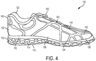
- extruded components may be extruded directly onto other portions of an article of footwear, such as article of footwear 100 shown in FIGS. 1-7 .
- article of footwear 100 may include a sole 110 and an upper 120.
- sole 110 and/or upper 120 include an extruded component.
- the component may be extruded onto a surface so as to provide an extruded component that extends above the surface at a certain width and height profile.
- the height, width, or geometry or physical appearance/characteristic of the extruded components may be dynamically changed as the components are extruded onto article of footwear 100, such as onto upper 120.
- the geometry or physical appearance/characteristics of the extruded components may be changed by dynamically changing the height of the nozzle (relative to the dispensing surface or substrate) from which the material, used to form the component, is extruded. In some embodiments, the geometry or physical appearance/characteristics of the extruded components may be changed by dynamically changing the speed at which the nozzle is moving as the material is extruded and the component is formed. In some embodiments, the geometry or physical appearance/characteristics of the extruded components may be changed by dynamically changing the flow rate of the material that is extruded. Other parameters may be changed to dynamically change the height, width, or other characteristic of the extruded components. In some embodiments, the density or viscosity of the extruded components maybe changed. For example, a low density extruded component may be used to form a collar of the upper 120.
- upper 120 has one or more panels 130 and one or more upper extruded components 140 that define all or a portion of the area of the upper.
- panels 130 comprise individual textile pieces.
- panels 130 may be made of leather, synthetic leather, plastic (e.g., thermoplastic film), mesh, textile, knit-goods, woven-goods, non-woven, or other suitable materials.
- panels 130 may be made of a knitted or woven fabric.
- panels 130 may be made of a non-knitted or non-woven fabric.
- upper 120 is a knit upper.
- upper 120 is a circular knit upper.
- a portion or the entirety of upper 120 may be circular knit.
- upper 120 is a 360 degree circular knit upper.
- upper 120 is a flat knit upper.
- a portion or the entirety of upper 120 may be flat knit.
- upper 120 comprises at least five panels 130. In some embodiments, upper 120 comprises at least ten panels 130. In some embodiments, panels 130 may differ from one another in size, shape, material, and/or other characteristics. In some embodiments, the characteristics vary based on desired functions of article of footwear 100 at particular locations.
- upper 120 comprises one or more panels 132 configured to provide additional support, such as in a heel region of upper 120. In some embodiments, panels 132 comprise a heel counter (see FIG. 3 ).
- upper comprises one or more panels 134 made of a first material and one or more panels 136 made of a second material. In some embodiments, panels 134 are made of a knitted fabric and panels 136 are made of a non-knitted fabric.
- upper extruded components 140 are extruded directly onto upper 120 (e.g., panels 130 of upper 120) to form a portion of upper 120.
- upper extruded components 140 may have a lower viscosity than other extruded components (e.g., extruded components in sole 110). Accordingly, upper extruded components 140 may be relatively flat on upper 120 (see, e.g., FIG. 2 ).
- upper extruded components 140 are disposed on an exterior portion of article of footwear 100. In some embodiments, upper extruded components 140 form an exterior portion of article of footwear 100.
- upper extruded components 140 provide aesthetic and functional features of article of footwear 100. In some embodiments, upper extruded components 140 may form a pattern on upper 120. In some embodiments, upper extruded components 140 may be a single, continuous element. In some embodiments, upper extruded components 140 may include a plurality of continuous elements.
- upper extruded components 140 include one or more extruded components 142 that are disposed along a border (i.e., transition) between two or more panels 130 or an area of overlap between two or more panels 130, one or more extruded components 144 that are disposed across (but not along a border between) one or more panels 130, and one or more extruded components 146 that completely surround a panel 130 along the border of panel 130.
- a single upper extruded component 140 may form both an extruded component 142 and an extruded component 144.
- a single upper extruded component 140 may form both an extruded component 142 and an extruded component 146.
- a single upper extruded component 140 may form both an extruded component 144 and an extruded component 146.
- upper extruded components 140 form part of a closure system for article of footwear.
- laces 150 extend through upper 120 between portions of upper extruded component 144. This may strengthen the hole that receives laces 150.
- upper extruded components 140 may provide a loop to receive laces 150.
- extruded components may support other components configured to receive laces 150.
- upper extruded components 140 join two or more panels 130 together.
- upper extruded components 140 are the only means for joining panels 130 together (i.e., panels 130 are not sewn, joined with an adhesive, joined with low-melt film, laser-welded, ultrasonically welded, radio-frequency welded, or otherwise joined together except by upper extruded components 140).
- panels 130 are joined together by upper extruded components 140 as well as being sewn, joined with an adhesive, laser-welded, ultrasonically welded, or radio-frequency welded.
- the seam may include one or more of upper extruded component 140, adhesive, stitching, or another suitable redundant joining method.
- the seam is a stitchless seam.
- the seam is a stitchless seam with an overlay.
- the seam is a butt seam.
- the seam is a hidden seam (e.g., closed seam).
- the seam is covered with seam tape.
- the seam may include upper extruded component 140 on an outer surface of upper 120 and seam tape on an inner surface of upper 120.
- the seam comprises an area of overlap between the two panels 130.
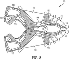
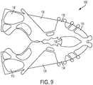
- FIGS. 8 and 9 a layout for an upper 120 is shown in FIGS. 8 and 9 .
- the various panels 130 making up upper 120 are joined together by upper extruded components 140.
- Some of upper extruded components 140 extend along the border between panels 130 (i.e., extruded components 142).
- Some of upper extruded components 140 extend across multiple panels 130, but not along a border between panels 130 (i.e., extruded components 144).
- Some of upper extruded components 140 extend to completely surround a panel 130 (i.e., extruded components 146).
- no additional element or means other than upper extruded components 140 joins panels 130 together.
- upper extruded components 140 are not limited to a particular design or configuration. Instead, upper extruded components 140 may be dispensed in a desired location to provide a desired function or aesthetic.
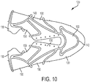
- An additional example of upper 120 is provided in FIGS. 10 and 11 .
- all upper extruded components 140 are extruded components 142 (i.e., all upper extruded components 140 extend along a border between panels 130).
- no additional element or means other than upper extruded components 140 joins panels 130 together.
- upper 120 is made by shaping a plurality of panels 130 to form parts of the upper.
- a first panel 130 maybe shaped to form part of upper 120.
- the first panel 130 may be cut to a particular shape.
- a second panel 130 may also be shaped to form another part of upper 120, for example, by cutting.
- the first and second panels 130 may be placed adjacent to each other.
- the first panel 130 may be abutted against the second panel 130 to form a border.
- a component 140 is extruded along a border between the first and second panels 130.
- extruded component 140 bonds with first and second panels 130 and thus joins first and second panels 130 together.
- component 140 is extruded onto panels 130 in a flat configuration.
- component 140 is extruded onto panels 130 in a three dimensional configuration (e.g., onto a contoured surface).
- component 140 may be extruded onto panels 130 when panels 130 are on a shoe last, a foot form, or any other three-dimensional form suitable for holding panels 130. While only two panels 130 are discussed here, additional panels 130 may be shaped to form other parts of upper 120 and components 140 may be extruded along each of the borders between panels 130 to join panels 130 together to form the entire upper 120. In some embodiments, one panel 130 may completely surround another panel 130.
- sole 110 comprises various layers of extruded components.
- sole 110 can provide the desired ride and feel characteristics to the wearer.
- sole 110 can minimize the weight of article of footwear 100; control the flexion, resilience, and support of article of footwear 100; and provide customized desired cushioning and shape for an article of footwear 100.
- sole 110 comprises an extruded component 112.
- extruded component 112 is disposed at the junction between sole 110 and upper 120.
- extruded component 112 forms an outer edge of sole 110 and/or upper 120.
- extruded component 112 is one continuous component that surrounds article of footwear 100.
- extruded component 112 provides a base component or layer around which the rest of sole 110 is made (see FIGS. 24-28 ).
- additional layers of extruded component(s) may be deposited adjacent to extruded component 112 to form a portion of sole 110, such as a midsole.
- one or more layers 114 of extruded component may be deposited adjacent to extruded component 112.
- layers 114 provide a midsole of sole 110.
- layers 114 are formed from one continuous extruded component.
- each layer 114 is formed from a separate continuous extruded component. In some embodiments, as shown in FIGS.
- the number of layers 114 varies along a length of the article of footwear 100.
- the extruded component of layers 114 may be extruded in a pattern, such as a loop-forming pattern back and forth across article of footwear 100 (e.g., in a longitudinal direction, a transverse direction, or an angled direction between a longitudinal direction and a transverse direction).
- the extruded component of layers 114 extends from a heel area of article of footwear 100 to a toe area of the article of footwear 100.
- the extruded component of layers 114 is discontinuous such that there are separate heel and forefoot extruded components.
- the extruded component of layers 114 is positioned only in a portion of sole 110 (e.g., heel area only, midfoot area only, forefoot area only, or a combination thereof).
- other portions of sole 110 may be made of foam.
- article of footwear 100 may include the extruded component of layers 114 only in the heel of sole 110 with foam in the forefoot of sole 110.
- article of footwear 100 may include the extruded component of layers 114 only in the forefoot of sole 110 with foam in the heel of sole 110.
- a heel lift may be created with the same number of layers 114 in the heel of sole 110 and in the forefoot of sole 110, but with the nozzle running faster in the forefoot and slower in the heel.
- one or more layers 116 of extruded component are deposited adjacent to layers 114 (i.e., underneath layers 114). In some embodiments, layers 116 provide an outsole of sole 110. In some embodiments, layers 116 are formed from one continuous extruded component. In some embodiments, each layer 116 is formed from a separate continuous extruded component. In some embodiments, the extruded component of layers 116 may be extruded in a pattern, such as an undulating pattern back and forth across article of footwear 100 (e.g., in a longitudinal direction, a transverse direction, or an angled direction between a longitudinal direction and a transverse direction). For example, as shown in FIG.
- sole 110 includes a layer 116 of an extruded component that extends back and forth in a transverse direction across article of footwear 100 in an undulating pattern and a layer 116 of an extruded component that extends back and forth in an angled direction (between the longitudinal and transverse directions) across article of footwear 100 in an undulating pattern.
- layers 116 differ from layers 114 in at least one characteristic (e.g., color, density, shape, size, material composition, etc.).
- layers 116 comprise a ground-contacting surface of article of footwear 100.
- sole 110 is made entirely of extruded components.
- layers 114, layer 116 and extruded component 112 may make up the entirety of sole 110.
- other materials or layers may be included in sole 110.
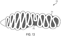
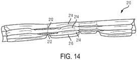
- a sole 210 for an article of footwear can include one or more extruded components formed in a controlled geometric pattern along with layers of non-extruded material.
- sole 210 can include one or more layers.
- one or more of the layers may comprise an extruded member.
- one or more of the layers may comprise a material that is not extruded.
- sole 210 includes layers 212 that comprise a material that is not extruded and layers 214 and/or layers 216 that comprise an extruded material.
- layers 214 may have similar characteristics as layers 114.
- layers 216 may have similar characteristics as layers 116.
- the extruded components of layers 214 and 216 may be aligned with each other such that they follow the same pattern.
- sole 210 comprises cushioning elements 218, as shown in FIG. 12 .
- cushioning elements 218 comprises an extruded component.
- cushioning elements 218 may be extruded into loops formed by layer 216.
- layer 216 and/or cushioning element 218 comprise a ground-contacting surface of the article of footwear.
- sole 210 comprises alternating layers (i.e., layers that comprise an extruded member (layers 214 and/or layers 216) alternating with layers that do not comprise an extruded member (layer 212)).
- layers 212 may be disposed between layers of extruded members (i.e., layers 214).
- a first layer 214 may be extruded in a controlled geometric pattern.
- a layer 212 may then be placed adjacent to first layer 214.
- a second layer 214 may then be extruded over layer 212 and first layer 214.
- layer 212 is secured between two extruded components. In some embodiments, this arrangement allows for components to be embedded within a midsole of an article of footwear.
- layers 212 comprise a mesh material.
- layers 212 comprise a nonwoven layer.
- layer 212 may be a film, a textile, a molded component, or other suitable material.
- layers 212 may extend beyond sole 210.
- layers 212 may extend up and attach to or form part of an upper.
- other components other than layer 212 may be disposed between layers 214 or between two or more extruded components.
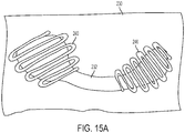
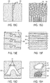
- extruded components 240 may be deposited in a variety of designs. In some embodiments, extruded component 240 may be deposited in a back and forth undulating pattern to secure upper parts 232 to a portion 230 of an upper. In some embodiments, extruded component 240 secures parts 232 to reduce stretching or moving of parts 232 around on the upper. In some embodiments, part 232 comprises a tip of the upper, as shown in FIG. 15A . In some embodiments, part 232 comprises a counter of the upper, as shown in FIG. 15B . In some embodiments, as shown in FIG.
- a non-continuous extruded component 242 may join panels 234 and 236 together. For example, a plurality of deposits of non-continuous extruded component 242 along a border between panels 234 and 236 may join panels 234 and 236 together.
- extruded component 240 may provide a pattern on a portion 230 of an upper.
- extruded component 240 may provide a pattern and join panels 234 and 236 together.
- FIG. 15C a non-continuous extruded component 242 may join panels 234 and 236 together.
- non-continuous extruded component 242 may secure part 232 onto a portion 230 of an upper without being deposited along a border of part 232, for example, if part 232 comprises a mesh material.
- material of non-continuous extruded component 242 e.g., extruded dots
- some parts 232 may be joined to portion 230 of the upper by an extruded component 240 deposited along a border of part 232, while other parts 232 may be joined to portion 230 of the upper by an extruded component deposited back and forth across part 232.
- the border between panels 234 and 236 may not be straight.
- the border between panels 234 and 236 may curve back and forth.
- extruded component 240 may curve back and forth along the border between panels 234 and 236.
- a segment of an extruded component may bond or stick to an article of footwear and another segment of the extruded component may not bond or stick to the article of footwear.
- having a bonded segment and a non-bonded segment of the extruded component allows a designated part of the article of footwear (e.g., the substrate) to stretch and move independently from the extruded component (and/or where the extruded component bonds to the substrate).
- the non-bonded segment of the extruded component may extend over a hole or void in the upper (and/or substrate).
- the non-bonded segment of the extruded component may extend over a tongue of the upper.
- the extruded component may be bonded to an article of footwear on both a medial side and a lateral side (e.g., at the feather line, at the quarters, etc.) and include a non-bonded segment that extends over a tongue of the upper.
- the non-bonded segment of the extruded component may extend over a portion of the upper to provide stress relief.
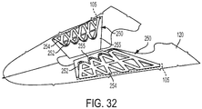
- the component is extruded over a non-stick material (see FIG. 32 ).
- a non-stick material is any material that does not bond with the extruded component as it hardens.
- the non-stick material may be removed after the extruded component has hardened, thus leaving a non-bonded segment of the extruded component.
- the non-stick material may be a temporary insert made from polytetrafluoroethylene (PTFE), or other suitable non-stick material.
- the non-stick material may be screen printed or sprayed over a portion of the article of footwear, such as a portion of a panel.
- a last on which the component is extruded may be made of or coated with the non-stick material.
- the article of footwear may have an upper that is completely knit (e.g., flat knit, circular knit, etc.) with areas of the knit upper comprising yarns that are inherently non-stick (e.g., PTFE yarns, polyolefin yarns, ultrahigh-molecular-weight polyethylene (UHMWPE) yarn).
- the upper may include woven, non-woven, or knit sections that are entirely made from non-stick yarns that are seamed together (i.e., stitched) to other upper panels that are made from traditional yarns (i.e., polyester, nylon, etc.) that may or may not be coated with the non-stick material.
- an entire extruded component 254 may be made as a non-bonded segment (i.e., the extruded component is dispensed only over a non-stick material to form a stand-alone component), as shown, for example, in FIG. 34 .
- the extruded component 254 may then be attached to an article of footwear.
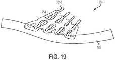
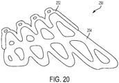
- the extruded component 254 maybe attached to an article of footwear as an upper support element 250.
- an extruded component that is a stand-alone component may be attached to an article of footwear as a heel counter.
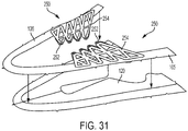
- a non-bonded segment of an extruded component 254 may form an upper support element 250 of article of footwear 100.
- upper support element 250 may provide support to the wearer in the midfoot region of article of footwear 100.
- upper support element 250 comprises a non-extruded component 252.
- non-extruded component 252 comprises loops to receive laces.
- upper support element 250 may comprise an additional layer 256.
- extruded component 254 is bonded to additional layer 256.
- additional layer 256 comprises a mesh material.
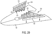
- upper support element 250 is attached to article of footwear 100. In some embodiments, as shown in FIG. 18 , upper support element 250 is attached to article of footwear 100 at attachment portion 105 of article of footwear 100. In some embodiments, attachment portion 105 comprises part of the upper of article of footwear 100. In some embodiments, attachment portion 105 comprises part of the sole of article of footwear 100. In some embodiments, attachment portion 105 is any other part of article of footwear 100 (e.g., between the sole and the upper). In some embodiments, attachment portion 105 may be disposed between the sole and the upper at the feather line of the article of footwear. In some embodiments, attachment portion 105 is tucked under portions of the upper and/or sole. For example, attachment portion 105 may be tucked under the midsole. In some embodiments, attachment portion 105 is bonded to an extruded component of the sole.
- attachment portion 105 is stitched to article of footwear 100. In some embodiments, attachment portion 105 is adhered to article of footwear 100 with an adhesive. For example, as shown in FIG. 29 , upper support element 250 is bonded to attachment portion 105 via extruded component 254 and attachment portion 105 is then attached to the rest of an upper 120 (e.g., via stitching, joined with an adhesive, laser-welded, ultrasonically welded, radio-frequency welded, low-melt film or any other suitable method for joining).
- attachment portion 105 is an integral part of article of footwear 100 and upper support element 250 is attached to article of footwear 100 via extruded component 254 (i.e., extruded component 254 bonds with attachment portion 105 as extruded component 254 hardens).
- extruded component 254 bonds with attachment portion 105 as extruded component 254 hardens.
- attachment portion 105 may be a part of upper 120.
- extruded component 254 bonds directly to upper 120.
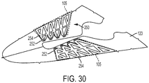
- extruded component 254 does not include a non-bonded segment (see FIG. 30 ).
- extruded component 254 includes a non-bonded segment (see FIG. 32 ).
- a removable non-stick component 255 may be inserted under portions of extruded component 254.
- attachment portion 105 comprises the randing 106 of article of footwear.
- Extruded component 254 may bond directly with randing 106.
- Other means of attaching upper support element 250 to article of footwear 100 may also be used.
- non-extruded component 252 may be embedded within extruded component 254.
- Non-extruded component 252 may take a variety of forms.
- non-extruded component 252 may comprise a piece of fabric that extends from extruded component 254 and includes a plurality of loops to receive laces, as shown, for example, in FIGS. 16 , 18 , and 20 .
- non-extruded component 252 may comprises a strip of fabric that extends across the top of extruded component 254 and includes a plurality of loops to receive laces, as shown in FIG. 17 .
- a gap 253 separates part of non-extruded component 252 from extruded component 254.
- non-extruded component 252 comprises a plurality of strips of material that extend from the bottom of extruded component 254 to beyond the top of extruded component 254, as shown in FIG. 19 .
- each strip of material comprises a loop to receive laces
- non-extruded component 252 comprises a yarn, thread, or string that extends across the top of extruded component 254, as shown in FIGS. 21 and 22 .
- Several portions of the yarn, thread, or string may be bonded with extruded component 254 while several other portions of the yarn, thread, or string are not bonded and form loops to receive laces.
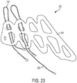
- non-extruded component 252 comprises a plurality of yarns, threads, or strings that extend from the bottom of extruded component 254 to beyond the top of extruded component 254, as shown in FIG. 23 .
- the plurality of yarns, threads, or strings also extend beyond the bottom of extruded component 254.
- a portion 258 of yarns, threads, or strings is configured to extend underneath upper (e.g., between upper and sole, or within sole).
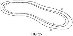
- a sole may be formed by vacuum forming a film 300, such as a polyurethane film, and extruding a component 310 into a groove formed in the vacuum formed film 300.
- component 310 may be similar to extruded component 112.
- one or more non-extruded components 252 may be placed over extruded component 310 and vacuum formed film 300, as shown in FIGS. 26 and 27 .
- portions 258 of non-extruded components 252 are disposed on an inside of the area formed by extruded component 310.
- layers of extruded component 320 may then be extruded over non-extruded component 252 and extruded component 310, thus securing non-extruded component 252 within the sole.
- Vacuum formed film 300 may be removed (see FIG. 28 ) after extruded components 310 and/or 320 have set.
- non-extruded component 252 may be placed between layers of extruded component 320.
- a sole may be formed without a vacuum formed film (e.g., via plasma coated rapid prototype tooling).
- an article of footwear 400 may comprise a sole 410 and an upper 420.
- sole 410 is made of extruded components.
- article of footwear 400 may comprise an upper extruded component 430.
- upper extruded component 430 may extend from a side of sole 410.
- upper extruded component 430 extends above sole 410.
- upper extruded component 430 may form a closure system for article of footwear 400.
- upper extruded component 430 may extend on the sides of upper 420 and have loops to receive laces.
- upper extruded component 430 may extend above sole 410 onto upper 420 in a toe region and a heel region of article of footwear 400.
- upper extruded component 430 may be bonded to article of footwear 400 at sole 410 and not bonded to article of footwear 400 at upper 420.
- upper 420 can move independent of upper extruded component 430 and upper extruded component 430 can move independent of upper 420.
- extruded components for sole 410 and upper extruded component 430 may be extruded or dispensed to a single substrate.
- Various embodiments described herein allow for joining of individual panels together via an extruded component and allow for the use of shapes and geometries that may be difficult to achieve with conventional molding techniques.
- Various embodiments described herein provide the use of extruded components to customize articles of footwear.
- Various embodiments described herein provide extruded components that have segments that are bonded to the article of footwear (e.g., bonded to the sole or upper) and segments that are not bonded. Further variations of the embodiments described above may also be provided.
Landscapes
- Engineering & Computer Science (AREA)
- Chemical & Material Sciences (AREA)
- Materials Engineering (AREA)
- Mechanical Engineering (AREA)
- Manufacturing & Machinery (AREA)
- Footwear And Its Accessory, Manufacturing Method And Apparatuses (AREA)
Claims (14)
- Schuhoberteil (120) für einen Schuhartikel, wobei das Schuhoberteil (120) umfasst:ein erstes oberes Einzelteil (130);ein zweites oberes Einzelteil (130); undeine extrudierte Komponente (140), die entlang einer Grenze zwischen des ersten oberen Einzelteils (130) und des zweiten oberen Einzelteils (130) angeordnet ist,wobei die extrudierte Komponente (140) das erste obere Einzelteil (130) mit dem zweiten oberen Einzelteil (130) verbindet; undwobei die extrudierte Komponente (140) einen Teil eines Verschlusssystems für den Schuhartikel (100) bildet.
- Schuhoberteil (120) nach Anspruch 1, wobei die extrudierte Komponente (140) Polyurethan umfasst.
- Schuhoberteil (120) nach Anspruch 1 oder 2, wobei sich ein Material des ersten oberen Einzelteils (130) von einem Material des zweiten oberen Einzelteils (130) unterscheidet.
- Schuhoberteil (120) nach einem der vorhergehenden Ansprüche, ferner umfassend eine Naht, die das erste obere Einzelteil (130) und das zweite obere Einzelteil (130) verbindet.
- Schuhoberteil (120) nach einem der vorhergehenden Ansprüche, wobei die extrudierte Komponente (140) eine Außenfläche des Schuhoberteils (120) bildet.
- Schuhoberteil (120) nach einem der vorhergehenden Ansprüche, ferner umfassend:ein drittes oberes Einzelteil (130); undeine zusätzliche extrudierte Komponente (140), die entlang einer Grenze zwischen des ersten oberen Einzelteils (130) und des dritten oberen Einzelteils (130) angeordnet ist,wobei die zusätzliche extrudierte Komponente (140) das erste obere Einzelteil (130) mit dem dritten oberen Einzelteil (130) verbindet.
- Schuhartikel (100) umfassend:eine Sohle (110);ein Schuhoberteil (120) gemäß einem der vorhergehenden Ansprüche.
- Schuhartikel (100) nach Anspruch 7, wobei die extrudierte Komponente (140) jede der Vielzahl von Einzelteilen (130) mit angrenzende Einzelteilen (130) verbindet, und wobei jede der Vielzahl von Einzelteilen (130) nur durch die extrudierte Komponente (140) miteinander verbunden ist.
- Schuhartikel (100) nach Anspruch 7 oder 8, wobei die Sohle (110) eine extrudierte Sohlenkomponente umfasst.
- Schuhartikel (100) nach Anspruch 9, wobei die extrudierte Sohlenkomponente sich über die Sohle (110) erstreckt, um ein Verschlusssystem für den Schuhartikel (100) zu bilden.
- Schuhartikel (100) nach einem der Ansprüche 7 bis 10, wobei mindestens ein Einzelteil der Vielzahl von Einzelteilen eine Fersenkappe umfasst.
- Verfahren zur Herstellung eines Schuhoberteils (120) nach einem der vorhergehenden Ansprüche für einen Schuhartikel (100), wobei das Verfahren umfasst:Formen eines ersten Einzelteils (130), um einen Teil des Schuhoberteils (120) zu bilden;Formen eines zweiten Einzelteils (130), um einen anderen Teil des Schuhoberteils (120) zu bilden;Anordnen des ersten Einzelteils (130) angrenzend zum zweiten Einzelteil (130); undExtrudieren einer Komponente (140) entlang einer Grenze zwischen dem ersten Einzelteil (130) und dem zweiten Einzelteil (130), um das erste Einzelteil (130) und das zweite Einzelteil (130) miteinander zu verbinden;wobei die extrudierte Komponente (140) einen Teil eines Verschlusssystems für den Schuhartikel (100) bildet.
- Verfahren nach Anspruch 12, wobei das Anordnen des ersten Einzelteils (130) angrenzend an das zweite Einzelteil (130) Anlegen des ersten Einzelteils (130) an das zweite Einzelteil (130) umfasst.
- Verfahren nach Anspruch 12 oder 13, wobei das erste Einzelteil (130) das zweite Einzelteil (130) vollständig umgibt.
Priority Applications (1)
| Application Number | Priority Date | Filing Date | Title |
|---|---|---|---|
| EP20164956.3A EP3689174B1 (de) | 2017-07-07 | 2018-07-03 | Schuhober mit extrudierten komponenten |
Applications Claiming Priority (1)
| Application Number | Priority Date | Filing Date | Title |
|---|---|---|---|
| US15/644,463 US10485302B2 (en) | 2017-07-07 | 2017-07-07 | Method of making an upper |
Related Child Applications (1)
| Application Number | Title | Priority Date | Filing Date |
|---|---|---|---|
| EP20164956.3A Division EP3689174B1 (de) | 2017-07-07 | 2018-07-03 | Schuhober mit extrudierten komponenten |
Publications (2)
| Publication Number | Publication Date |
|---|---|
| EP3424360A1 EP3424360A1 (de) | 2019-01-09 |
| EP3424360B1 true EP3424360B1 (de) | 2020-03-25 |
Family
ID=62846067
Family Applications (2)
| Application Number | Title | Priority Date | Filing Date |
|---|---|---|---|
| EP18181464.1A Active EP3424360B1 (de) | 2017-07-07 | 2018-07-03 | Schuhober mit extrudierten komponenten für schuhartikel |
| EP20164956.3A Active EP3689174B1 (de) | 2017-07-07 | 2018-07-03 | Schuhober mit extrudierten komponenten |
Family Applications After (1)
| Application Number | Title | Priority Date | Filing Date |
|---|---|---|---|
| EP20164956.3A Active EP3689174B1 (de) | 2017-07-07 | 2018-07-03 | Schuhober mit extrudierten komponenten |
Country Status (3)
| Country | Link |
|---|---|
| US (4) | US10485302B2 (de) |
| EP (2) | EP3424360B1 (de) |
| CN (1) | CN109198793B (de) |
Families Citing this family (17)
| Publication number | Priority date | Publication date | Assignee | Title |
|---|---|---|---|---|
| MX392120B (es) | 2015-10-02 | 2025-03-21 | Nike Innovate Cv | Placa para calzado. |
| US10441027B2 (en) * | 2015-10-02 | 2019-10-15 | Nike, Inc. | Footwear plate |
| US10448704B2 (en) | 2015-10-02 | 2019-10-22 | Nike, Inc. | Plate with foam for footwear |
| USD807621S1 (en) | 2016-07-13 | 2018-01-16 | Reebok International Limited | Shoe |
| CN112971269B (zh) | 2016-07-20 | 2022-12-16 | 耐克创新有限合伙公司 | 用于鞋类制品或装备的复合板 |
| CN113261746B (zh) | 2016-07-20 | 2023-02-17 | 耐克创新有限合伙公司 | 鞋板 |
| US20190166952A1 (en) * | 2017-12-05 | 2019-06-06 | Reebok International Limited | Article of footwear with dispensed saddle |
| WO2019204202A1 (en) | 2018-04-16 | 2019-10-24 | Nike Innovate C.V. | Outsole plate |
| US11344078B2 (en) | 2018-04-16 | 2022-05-31 | Nike, Inc. | Outsole plate |
| US10993497B2 (en) | 2018-11-15 | 2021-05-04 | Under Armour, Inc. | Article with ribbon loops for string lasting |
| AU2019424137A1 (en) * | 2019-01-24 | 2021-01-07 | Asics Corporation | Shoe having counter |
| CN113382654B (zh) * | 2019-12-25 | 2024-07-09 | 株式会社爱世克私 | 鞋的鞋面和鞋的鞋面的制造方法 |
| USD936351S1 (en) * | 2021-02-02 | 2021-11-23 | Nike, Inc. | Shoe |
| US12102189B2 (en) | 2022-05-27 | 2024-10-01 | Shimano Inc. | Upper for shoe |
| USD1037633S1 (en) | 2022-06-09 | 2024-08-06 | On Clouds Gmbh | Shoe |
| US12150513B2 (en) * | 2022-09-14 | 2024-11-26 | Lululemon Athletica Canada Inc. | Upper for article of footwear incorporating a knitted butterfly workpiece |
| US20260053232A1 (en) * | 2024-08-20 | 2026-02-26 | Amer Sports Canada Inc. | Footwear |
Family Cites Families (109)
| Publication number | Priority date | Publication date | Assignee | Title |
|---|---|---|---|---|
| GB596562A (en) * | 1945-07-30 | 1948-01-06 | Adolph Reiter | Laces and method of manufacturing the same |
| US2100492A (en) | 1933-10-23 | 1937-11-30 | Converse Rubber Company | Pneumatic sheet material and method of making |
| US2325656A (en) * | 1940-11-28 | 1943-08-03 | United Shoe Machinery Corp | Reinforcing shoe parts |
| US2760282A (en) * | 1953-12-28 | 1956-08-28 | B B Chem Co | Temporary protection of narrow areas |
| US3008862A (en) * | 1956-06-29 | 1961-11-14 | Union Carbide Corp | Extruded bead sealing |
| US2862543A (en) * | 1957-02-18 | 1958-12-02 | Stanley J Kaminsky | Tool for welding thermo-plastic materials |
| US3251728A (en) | 1962-09-10 | 1966-05-17 | Dow Chemical Co | Stranded aliphatic olefin polymer foam for loose-fill packaging |
| DE1279314B (de) | 1964-10-01 | 1968-10-03 | Desma Werke Gmbh | Form zum Herstellen einer mehrschichtigen, insbesondere zweifarbigen Sohle aus elastischem Werkstoff, insbesondere Kunststoff |
| FR2088626A5 (de) | 1970-04-20 | 1972-01-07 | Paritzky Ets | |
| USRE29041E (en) * | 1970-06-23 | 1976-11-23 | Footwear | |
| US3672078A (en) * | 1970-06-23 | 1972-06-27 | Tatsuo Fukuoka | Footwear |
| US3911173A (en) * | 1973-02-05 | 1975-10-07 | Usm Corp | Adhesive process |
| US4034431A (en) * | 1973-10-03 | 1977-07-12 | Tatsuo Fukuoka | Method for manufacturing a footwear |
| US3952358A (en) * | 1973-10-03 | 1976-04-27 | Tatsuo Fukuoka | Shoe and a method for manufacturing the same |
| US4150455A (en) * | 1973-10-03 | 1979-04-24 | Tatsuo Fukuoka | Method for manufacturing a footwear and footwear |
| JPS51129340A (en) * | 1975-04-30 | 1976-11-10 | Tatsuo Fukuoka | Method of producing clogs |
| US3893777A (en) * | 1974-07-31 | 1975-07-08 | Wilson M Jones | Structural joint |
| US4272898A (en) | 1976-03-11 | 1981-06-16 | Tansill Horace A | Resin-coated fiber mass containing catalyst-filled hollow fibers |
| US4342160A (en) * | 1978-11-17 | 1982-08-03 | Clarks Limited | Footwear |
| US4272989A (en) | 1979-09-04 | 1981-06-16 | Pullman Berry | Instrument lance for basic oxygen steelmaking furnace |
| DE3038306C2 (de) | 1980-10-10 | 1984-03-22 | Hermann Berstorff Maschinenbau Gmbh, 3000 Hannover | Strangpreßvorrichtung zur Herstellung von geschäumtem, thermoplastischem Kunststoff |
| JPS6014805A (ja) | 1983-07-01 | 1985-01-25 | ウルヴリン・ワ−ルド・ワイド・インコ−ポレイテツド | 予形成構造体を有する運動靴用靴底 |
| CH662484A5 (de) | 1983-09-29 | 1987-10-15 | Bata Schuhe Ag | Modular aufgebaute tretunterlage. |
| US4536974A (en) | 1983-11-04 | 1985-08-27 | Cohen Elie | Shoe with deflective and compressionable mid-sole |
| US4611412A (en) | 1983-11-04 | 1986-09-16 | Cohen Elie | Shoe sole with deflective mid-sole |
| US4952450A (en) | 1985-11-19 | 1990-08-28 | Noel, Marquet & Cie. S.A. | Foam panel and block constructions |
| US5188693A (en) * | 1986-04-18 | 1993-02-23 | Aishin Kakou K.K. | Process for applying polyvinyl chloride sealing material having low thixotropic index |
| US4753021A (en) | 1987-07-08 | 1988-06-28 | Cohen Elie | Shoe with mid-sole including compressible bridging elements |
| US4754559A (en) | 1987-05-27 | 1988-07-05 | Cohen Elie | Shoe with midsole including deflection inhibiting inserts |
| US5233767A (en) | 1990-02-09 | 1993-08-10 | Hy Kramer | Article of footwear having improved midsole |
| US5063018A (en) | 1990-06-04 | 1991-11-05 | Cordis Corporation | Extrusion method |
| CN1066620C (zh) | 1992-06-19 | 2001-06-06 | 铃木总业株式会社 | 凹凸成形层及其制造方法 |
| US5916006A (en) | 1994-06-27 | 1999-06-29 | Handsontoys, Inc. | Flexible foam construction toy set |
| US5692319A (en) * | 1995-06-07 | 1997-12-02 | Nike, Inc. | Article of footwear with 360° wrap fit closure system |
| IT1281968B1 (it) | 1995-07-14 | 1998-03-06 | Diadora Spa | Struttura composita di intersuola |
| BR9610996A (pt) * | 1995-08-29 | 1999-07-13 | Fidia Advanced Biopolymers Srl | Biomateriais para prevenção de ades es pós-cirúrgicas compreendendo derivados de ácidos hialurônico |
| US5713140A (en) | 1996-03-04 | 1998-02-03 | Baggenstoss; Alois C. | Resilient shoe sole |
| US7192069B1 (en) | 1996-06-27 | 2007-03-20 | Handle It Llc | Wrap for bundling objects |
| DE69823955T2 (de) | 1997-03-04 | 2005-06-16 | Technology Finance Corp. (Pty.) Ltd., Sandton | Als knochenimplantat geeignetes erzeugnis |
| DE19724592C1 (de) * | 1997-06-11 | 1998-10-15 | Grammer Formteile Gmbh | Verdeck für ein Kraftfahrzeug |
| KR100573611B1 (ko) * | 1998-09-11 | 2006-04-26 | 나이키 인코포레이티드 | 가요성 막 |
| US6248276B1 (en) * | 1999-01-15 | 2001-06-19 | Velcro Industries B.V. | Fasteners and methods of making fasteners |
| DE10037728C1 (de) | 2000-08-02 | 2002-02-21 | Adidas Int Bv | Schuh, insbesondere Laufschuh und Verfahren zu seiner Herstellung |
| JP3851182B2 (ja) * | 2002-02-06 | 2006-11-29 | トヨタ紡織株式会社 | 重ね結合されたボード製品およびその結合方法 |
| JP3939643B2 (ja) * | 2002-03-19 | 2007-07-04 | ピジョン株式会社 | 靴 |
| ITMI20020626A1 (it) * | 2002-03-26 | 2003-09-26 | Nextec Srl | Calzatura impermeabile e procedimento per la sua fabbricazione |
| US7401419B2 (en) | 2002-07-31 | 2008-07-22 | Adidas International Marketing B.V, | Structural element for a shoe sole |
| DE102005006267B3 (de) | 2005-02-11 | 2006-03-16 | Adidas International Marketing B.V. | Schuhsohle und Schuh |
| DE102005006737A1 (de) | 2005-02-15 | 2006-08-24 | Voith Fabrics Patent Gmbh | 3-D Polymer Extrusion |
| US7707743B2 (en) | 2006-05-19 | 2010-05-04 | Nike, Inc. | Article of footwear with multi-layered support assembly |
| CN101484496B (zh) | 2006-07-12 | 2012-06-27 | 三菱化学株式会社 | 聚氨酯的制造方法及由该制造方法得到的聚氨酯的用途 |
| US8435617B2 (en) * | 2006-08-17 | 2013-05-07 | W. L. Gore & Associates, Inc. | Stitchless seam system for joining laminates |
| US8544191B2 (en) * | 2007-04-10 | 2013-10-01 | Reebok International Limited | Smooth shoe uppers and methods for producing them |
| US20080271339A1 (en) | 2007-05-02 | 2008-11-06 | Fischer James R | Extruded Cushioning Insole |
| US7941941B2 (en) | 2007-07-13 | 2011-05-17 | Nike, Inc. | Article of footwear incorporating foam-filled elements and methods for manufacturing the foam-filled elements |
| US7926204B2 (en) | 2007-10-11 | 2011-04-19 | Nike, Inc. | Article of footwear with tubular sole assembly and method of manufacture |
| US9572402B2 (en) | 2007-10-23 | 2017-02-21 | Nike, Inc. | Articles and methods of manufacturing articles |
| KR101607340B1 (ko) | 2007-10-29 | 2016-03-29 | 야론 엘리아시 | 주문형 품목을 생산하기 위한 장치 및 방법 |
| US20100011619A1 (en) * | 2008-07-16 | 2010-01-21 | Peter Bastianelli | Method and apparatus for one piece footwear construction |
| ES2346393B1 (es) * | 2009-03-26 | 2011-09-14 | Adrian Hernandez Hernandez | Procedimiento de fabricacion de calzado. |
| US9015962B2 (en) | 2010-03-26 | 2015-04-28 | Reebok International Limited | Article of footwear with support element |
| US9392843B2 (en) | 2009-07-21 | 2016-07-19 | Reebok International Limited | Article of footwear having an undulating sole |
| US9420848B2 (en) | 2013-02-21 | 2016-08-23 | Nike, Inc. | Article of footwear incorporating a chamber system and methods for manufacturing the chamber system |
| KR20110010287U (ko) * | 2010-04-26 | 2011-11-02 | 이정우 | 마사지 기능을 갖춘 세족 슬리퍼 |
| US8578632B2 (en) * | 2010-07-19 | 2013-11-12 | Nike, Inc. | Decoupled foot stabilizer system |
| KR101073810B1 (ko) | 2010-12-07 | 2011-10-17 | (주)지원에프알에스 | 충격분산과 구름보행을 위한 추진식 신발창 |
| US8726540B2 (en) | 2011-01-13 | 2014-05-20 | SR Holdings, LLC | Footwear |
| TW201230976A (en) * | 2011-01-20 | 2012-08-01 | Jah Yih Entpr Co Ltd | Multilayer modular shoe upper and manufacturing method thereof |
| US8875418B2 (en) * | 2011-02-04 | 2014-11-04 | Nike, Inc. | Tendon assembly for an article of footwear |
| US8789295B2 (en) * | 2011-02-08 | 2014-07-29 | Wolverine World Wide, Inc. | Footwear and related method of manufacture |
| US8800172B2 (en) * | 2011-04-04 | 2014-08-12 | Nike, Inc. | Article of footwear having a knit upper with a polymer layer |
| US20130312284A1 (en) * | 2011-05-27 | 2013-11-28 | Nike, Inc. | Article of Footwear Having Welded Upper |
| US8844167B2 (en) * | 2011-07-18 | 2014-09-30 | Nike, Inc. | Article of footwear having an upper with cord elements |
| US20130025157A1 (en) * | 2011-07-27 | 2013-01-31 | Nike, Inc. | Upper with Zonal Contouring and Fabrication of Same |
| US9414638B2 (en) * | 2011-08-02 | 2016-08-16 | Nike, Inc. | Golf shoe with natural motion structures |
| EP2815668B1 (de) * | 2012-02-17 | 2019-02-06 | ASICS Corporation | Schuh und herstellungsverfahren dafür |
| US20130260104A1 (en) | 2012-04-03 | 2013-10-03 | Nike, Inc. | Yarns, Threads, And Textiles Incorporating A Thermoplastic Polymer Material |
| US9955750B2 (en) | 2012-07-10 | 2018-05-01 | Reebok International Limited | Article of footwear with sole projections |
| US9005710B2 (en) * | 2012-07-19 | 2015-04-14 | Nike, Inc. | Footwear assembly method with 3D printing |
| US8993061B2 (en) | 2012-07-19 | 2015-03-31 | Nike, Inc. | Direct printing to fabric |
| US20140130375A1 (en) * | 2012-11-15 | 2014-05-15 | Nike, Inc. | Article Of Footwear Incorporating A Knitted Component |
| CN108741393B (zh) | 2012-12-19 | 2021-06-11 | 新平衡运动公司 | 定制鞋类以及用于设计且制造其的方法 |
| ITTV20130007A1 (it) * | 2013-01-23 | 2014-07-24 | O L M Sportech Srl | Metodo di produzione di una rastrelliera per un gancio di chiusura per calzature sportive. |
| US10085516B2 (en) * | 2013-02-26 | 2018-10-02 | Nike, Inc. | Article of footwear with reinforced elastic upper |
| US10945488B2 (en) | 2013-08-09 | 2021-03-16 | Reebok International Limited | Article of footwear with extruded components |
| US10092058B2 (en) * | 2013-09-05 | 2018-10-09 | Nike, Inc. | Method of forming an article of footwear incorporating a knitted upper with tensile strand |
| US9241536B2 (en) * | 2013-09-27 | 2016-01-26 | Nike, Inc. | Uppers and sole structures for articles of footwear |
| DE102014202432B4 (de) * | 2014-02-11 | 2017-07-27 | Adidas Ag | Verbesserter Fußballschuh |
| US9861162B2 (en) * | 2014-04-08 | 2018-01-09 | Nike, Inc. | Components for articles of footwear including lightweight, selectively supported textile components |
| US9872537B2 (en) * | 2014-04-08 | 2018-01-23 | Nike, Inc. | Components for articles of footwear including lightweight, selectively supported textile components |
| US9629418B2 (en) * | 2014-04-15 | 2017-04-25 | Nike, Inc. | Footwear having motorized adjustment system and elastic upper |
| US9676159B2 (en) * | 2014-05-09 | 2017-06-13 | Nike, Inc. | Method for forming three-dimensional structures with different material portions |
| DE102014220087B4 (de) * | 2014-10-02 | 2016-05-12 | Adidas Ag | Flachgestricktes Schuhoberteil für Sportschuhe |
| US9474331B2 (en) | 2015-02-03 | 2016-10-25 | Nike, Inc. | Method of making an article of footwear having printed structures |
| US9788607B2 (en) * | 2015-02-20 | 2017-10-17 | Nike, Inc. | Article of footwear incorporating printed portions |
| US9756899B2 (en) * | 2015-02-20 | 2017-09-12 | Nike, Inc. | Article of footwear having an upper with connectors for attaching to a sole structure |
| DE102015208763A1 (de) * | 2015-05-12 | 2016-11-17 | Adidas Ag | Anpassbares Schuhoberteil und anpassbare Sohle |
| US9968161B2 (en) * | 2015-05-28 | 2018-05-15 | Brooks Sports, Inc. | Shoe constructions having upper assemblies with independently movable booties and decoupled sole assemblies |
| US10471671B2 (en) | 2015-11-09 | 2019-11-12 | Nike, Inc. | Three-dimensional printing along a curved surface |
| CN112890373B (zh) * | 2015-12-07 | 2023-05-09 | 耐克创新有限合伙公司 | 利用束缚元件进行三维印刷 |
| DE102015224885B4 (de) * | 2015-12-10 | 2024-11-07 | Adidas Ag | Verfahren für die Platzierung von Patches und hergestellte Artikel |
| KR102244578B1 (ko) * | 2016-01-19 | 2021-04-23 | 나이키 이노베이트 씨.브이. | 피추적 요소의 3차원 프린팅 |
| US10206453B2 (en) * | 2016-02-12 | 2019-02-19 | Wolverine Outdoors, Inc. | Footwear including a support cage |
| KR102220094B1 (ko) * | 2017-02-23 | 2021-03-02 | 더블유.엘.고어 앤드 어소시에이츠 게엠베하 | 기능성 멤브레인을 갖는 층상 제품, 상기 층상 제품을 포함하는 신발류 및 제조 방법 |
| US10765173B2 (en) * | 2017-03-10 | 2020-09-08 | Under Armour, Inc. | Article of footwear with reconfigurable fastening system |
| CN110461183B (zh) * | 2017-03-17 | 2022-03-29 | 耐克创新有限合伙公司 | 田径鞋的鞋头部分 |
| DE202017103049U1 (de) * | 2017-05-19 | 2017-06-27 | Isotech Holding Corporation Llc | Schuhschaft mit dreidimensionalen Ziermustern aus Polyurethan sowie Schuh mit dem derartigen Schuhschaft |
| US20180339478A1 (en) * | 2017-05-25 | 2018-11-29 | Isotech Holding Corporation Llc | Upper with 3-dimentional polyurethane pattern, method for manufacturing the same and shoe produced by the same |
| US11278081B2 (en) * | 2018-10-10 | 2022-03-22 | Reebok International Limited | Article of footwear with dispensed components |
-
2017
- 2017-07-07 US US15/644,463 patent/US10485302B2/en active Active
-
2018
- 2018-07-03 EP EP18181464.1A patent/EP3424360B1/de active Active
- 2018-07-03 EP EP20164956.3A patent/EP3689174B1/de active Active
- 2018-07-04 CN CN201810724391.XA patent/CN109198793B/zh active Active
- 2018-07-27 US US16/047,821 patent/US10568387B2/en active Active
-
2019
- 2019-11-22 US US16/692,555 patent/US20200085143A1/en not_active Abandoned
-
2020
- 2020-01-31 US US16/778,741 patent/US20200163415A1/en not_active Abandoned
Non-Patent Citations (1)
| Title |
|---|
| None * |
Also Published As
| Publication number | Publication date |
|---|---|
| US20190008234A1 (en) | 2019-01-10 |
| EP3689174A1 (de) | 2020-08-05 |
| US20200085143A1 (en) | 2020-03-19 |
| CN109198793B (zh) | 2021-10-29 |
| EP3424360A1 (de) | 2019-01-09 |
| US20190014862A1 (en) | 2019-01-17 |
| US20200163415A1 (en) | 2020-05-28 |
| EP3689174B1 (de) | 2023-06-07 |
| US10485302B2 (en) | 2019-11-26 |
| CN109198793A (zh) | 2019-01-15 |
| US10568387B2 (en) | 2020-02-25 |
Similar Documents
| Publication | Publication Date | Title |
|---|---|---|
| US10568387B2 (en) | Method of making an article of footwear with extruded components | |
| US11980251B2 (en) | Article of footwear with knitted component having plurality of graduated projections | |
| EP3494822B1 (de) | Schuhwerk mit verteiltem sattel | |
| US12042011B2 (en) | Molded footwear upper and method of making same | |
| CN112512364B (zh) | 包含针织部件和接纳带部件的鞋类物品 | |
| US11083246B2 (en) | Footwear with embroidery transition between materials | |
| TWI692319B (zh) | 具有防滑構件之編織組件及製造用於一鞋類物件之一鞋底系統之方法 | |
| WO2018129139A1 (en) | Composite soles | |
| US20260053232A1 (en) | Footwear |
Legal Events
| Date | Code | Title | Description |
|---|---|---|---|
| PUAI | Public reference made under article 153(3) epc to a published international application that has entered the european phase |
Free format text: ORIGINAL CODE: 0009012 |
|
| STAA | Information on the status of an ep patent application or granted ep patent |
Free format text: STATUS: REQUEST FOR EXAMINATION WAS MADE |
|
| 17P | Request for examination filed |
Effective date: 20180703 |
|
| AK | Designated contracting states |
Kind code of ref document: A1 Designated state(s): AL AT BE BG CH CY CZ DE DK EE ES FI FR GB GR HR HU IE IS IT LI LT LU LV MC MK MT NL NO PL PT RO RS SE SI SK SM TR |
|
| AX | Request for extension of the european patent |
Extension state: BA ME |
|
| GRAP | Despatch of communication of intention to grant a patent |
Free format text: ORIGINAL CODE: EPIDOSNIGR1 |
|
| STAA | Information on the status of an ep patent application or granted ep patent |
Free format text: STATUS: GRANT OF PATENT IS INTENDED |
|
| INTG | Intention to grant announced |
Effective date: 20191028 |
|
| GRAS | Grant fee paid |
Free format text: ORIGINAL CODE: EPIDOSNIGR3 |
|
| GRAA | (expected) grant |
Free format text: ORIGINAL CODE: 0009210 |
|
| STAA | Information on the status of an ep patent application or granted ep patent |
Free format text: STATUS: THE PATENT HAS BEEN GRANTED |
|
| AK | Designated contracting states |
Kind code of ref document: B1 Designated state(s): AL AT BE BG CH CY CZ DE DK EE ES FI FR GB GR HR HU IE IS IT LI LT LU LV MC MK MT NL NO PL PT RO RS SE SI SK SM TR |
|
| REG | Reference to a national code |
Ref country code: GB Ref legal event code: FG4D |
|
| REG | Reference to a national code |
Ref country code: DE Ref legal event code: R096 Ref document number: 602018003234 Country of ref document: DE |
|
| REG | Reference to a national code |
Ref country code: AT Ref legal event code: REF Ref document number: 1247520 Country of ref document: AT Kind code of ref document: T Effective date: 20200415 Ref country code: IE Ref legal event code: FG4D |
|
| PG25 | Lapsed in a contracting state [announced via postgrant information from national office to epo] |
Ref country code: FI Free format text: LAPSE BECAUSE OF FAILURE TO SUBMIT A TRANSLATION OF THE DESCRIPTION OR TO PAY THE FEE WITHIN THE PRESCRIBED TIME-LIMIT Effective date: 20200325 Ref country code: NO Free format text: LAPSE BECAUSE OF FAILURE TO SUBMIT A TRANSLATION OF THE DESCRIPTION OR TO PAY THE FEE WITHIN THE PRESCRIBED TIME-LIMIT Effective date: 20200625 Ref country code: RS Free format text: LAPSE BECAUSE OF FAILURE TO SUBMIT A TRANSLATION OF THE DESCRIPTION OR TO PAY THE FEE WITHIN THE PRESCRIBED TIME-LIMIT Effective date: 20200325 |
|
| PG25 | Lapsed in a contracting state [announced via postgrant information from national office to epo] |
Ref country code: HR Free format text: LAPSE BECAUSE OF FAILURE TO SUBMIT A TRANSLATION OF THE DESCRIPTION OR TO PAY THE FEE WITHIN THE PRESCRIBED TIME-LIMIT Effective date: 20200325 Ref country code: GR Free format text: LAPSE BECAUSE OF FAILURE TO SUBMIT A TRANSLATION OF THE DESCRIPTION OR TO PAY THE FEE WITHIN THE PRESCRIBED TIME-LIMIT Effective date: 20200626 Ref country code: LV Free format text: LAPSE BECAUSE OF FAILURE TO SUBMIT A TRANSLATION OF THE DESCRIPTION OR TO PAY THE FEE WITHIN THE PRESCRIBED TIME-LIMIT Effective date: 20200325 Ref country code: SE Free format text: LAPSE BECAUSE OF FAILURE TO SUBMIT A TRANSLATION OF THE DESCRIPTION OR TO PAY THE FEE WITHIN THE PRESCRIBED TIME-LIMIT Effective date: 20200325 Ref country code: BG Free format text: LAPSE BECAUSE OF FAILURE TO SUBMIT A TRANSLATION OF THE DESCRIPTION OR TO PAY THE FEE WITHIN THE PRESCRIBED TIME-LIMIT Effective date: 20200625 |
|
| REG | Reference to a national code |
Ref country code: NL Ref legal event code: MP Effective date: 20200325 |
|
| REG | Reference to a national code |
Ref country code: LT Ref legal event code: MG4D |
|
| PG25 | Lapsed in a contracting state [announced via postgrant information from national office to epo] |
Ref country code: NL Free format text: LAPSE BECAUSE OF FAILURE TO SUBMIT A TRANSLATION OF THE DESCRIPTION OR TO PAY THE FEE WITHIN THE PRESCRIBED TIME-LIMIT Effective date: 20200325 |
|
| PG25 | Lapsed in a contracting state [announced via postgrant information from national office to epo] |
Ref country code: EE Free format text: LAPSE BECAUSE OF FAILURE TO SUBMIT A TRANSLATION OF THE DESCRIPTION OR TO PAY THE FEE WITHIN THE PRESCRIBED TIME-LIMIT Effective date: 20200325 Ref country code: SM Free format text: LAPSE BECAUSE OF FAILURE TO SUBMIT A TRANSLATION OF THE DESCRIPTION OR TO PAY THE FEE WITHIN THE PRESCRIBED TIME-LIMIT Effective date: 20200325 Ref country code: LT Free format text: LAPSE BECAUSE OF FAILURE TO SUBMIT A TRANSLATION OF THE DESCRIPTION OR TO PAY THE FEE WITHIN THE PRESCRIBED TIME-LIMIT Effective date: 20200325 Ref country code: RO Free format text: LAPSE BECAUSE OF FAILURE TO SUBMIT A TRANSLATION OF THE DESCRIPTION OR TO PAY THE FEE WITHIN THE PRESCRIBED TIME-LIMIT Effective date: 20200325 Ref country code: CZ Free format text: LAPSE BECAUSE OF FAILURE TO SUBMIT A TRANSLATION OF THE DESCRIPTION OR TO PAY THE FEE WITHIN THE PRESCRIBED TIME-LIMIT Effective date: 20200325 Ref country code: PT Free format text: LAPSE BECAUSE OF FAILURE TO SUBMIT A TRANSLATION OF THE DESCRIPTION OR TO PAY THE FEE WITHIN THE PRESCRIBED TIME-LIMIT Effective date: 20200818 Ref country code: SK Free format text: LAPSE BECAUSE OF FAILURE TO SUBMIT A TRANSLATION OF THE DESCRIPTION OR TO PAY THE FEE WITHIN THE PRESCRIBED TIME-LIMIT Effective date: 20200325 Ref country code: IS Free format text: LAPSE BECAUSE OF FAILURE TO SUBMIT A TRANSLATION OF THE DESCRIPTION OR TO PAY THE FEE WITHIN THE PRESCRIBED TIME-LIMIT Effective date: 20200725 |
|
| REG | Reference to a national code |
Ref country code: AT Ref legal event code: MK05 Ref document number: 1247520 Country of ref document: AT Kind code of ref document: T Effective date: 20200325 |
|
| REG | Reference to a national code |
Ref country code: DE Ref legal event code: R097 Ref document number: 602018003234 Country of ref document: DE |
|
| PG25 | Lapsed in a contracting state [announced via postgrant information from national office to epo] |
Ref country code: ES Free format text: LAPSE BECAUSE OF FAILURE TO SUBMIT A TRANSLATION OF THE DESCRIPTION OR TO PAY THE FEE WITHIN THE PRESCRIBED TIME-LIMIT Effective date: 20200325 Ref country code: IT Free format text: LAPSE BECAUSE OF FAILURE TO SUBMIT A TRANSLATION OF THE DESCRIPTION OR TO PAY THE FEE WITHIN THE PRESCRIBED TIME-LIMIT Effective date: 20200325 Ref country code: AT Free format text: LAPSE BECAUSE OF FAILURE TO SUBMIT A TRANSLATION OF THE DESCRIPTION OR TO PAY THE FEE WITHIN THE PRESCRIBED TIME-LIMIT Effective date: 20200325 Ref country code: DK Free format text: LAPSE BECAUSE OF FAILURE TO SUBMIT A TRANSLATION OF THE DESCRIPTION OR TO PAY THE FEE WITHIN THE PRESCRIBED TIME-LIMIT Effective date: 20200325 |
|
| PLBE | No opposition filed within time limit |
Free format text: ORIGINAL CODE: 0009261 |
|
| STAA | Information on the status of an ep patent application or granted ep patent |
Free format text: STATUS: NO OPPOSITION FILED WITHIN TIME LIMIT |
|
| PG25 | Lapsed in a contracting state [announced via postgrant information from national office to epo] |
Ref country code: MC Free format text: LAPSE BECAUSE OF FAILURE TO SUBMIT A TRANSLATION OF THE DESCRIPTION OR TO PAY THE FEE WITHIN THE PRESCRIBED TIME-LIMIT Effective date: 20200325 Ref country code: PL Free format text: LAPSE BECAUSE OF FAILURE TO SUBMIT A TRANSLATION OF THE DESCRIPTION OR TO PAY THE FEE WITHIN THE PRESCRIBED TIME-LIMIT Effective date: 20200325 |
|
| 26N | No opposition filed |
Effective date: 20210112 |
|
| REG | Reference to a national code |
Ref country code: BE Ref legal event code: MM Effective date: 20200731 |
|
| PG25 | Lapsed in a contracting state [announced via postgrant information from national office to epo] |
Ref country code: LU Free format text: LAPSE BECAUSE OF NON-PAYMENT OF DUE FEES Effective date: 20200703 Ref country code: IE Free format text: LAPSE BECAUSE OF NON-PAYMENT OF DUE FEES Effective date: 20200703 |
|
| PG25 | Lapsed in a contracting state [announced via postgrant information from national office to epo] |
Ref country code: SI Free format text: LAPSE BECAUSE OF FAILURE TO SUBMIT A TRANSLATION OF THE DESCRIPTION OR TO PAY THE FEE WITHIN THE PRESCRIBED TIME-LIMIT Effective date: 20200325 Ref country code: BE Free format text: LAPSE BECAUSE OF NON-PAYMENT OF DUE FEES Effective date: 20200731 |
|
| REG | Reference to a national code |
Ref country code: CH Ref legal event code: PL |
|
| PG25 | Lapsed in a contracting state [announced via postgrant information from national office to epo] |
Ref country code: LI Free format text: LAPSE BECAUSE OF NON-PAYMENT OF DUE FEES Effective date: 20210731 Ref country code: CH Free format text: LAPSE BECAUSE OF NON-PAYMENT OF DUE FEES Effective date: 20210731 |
|
| PG25 | Lapsed in a contracting state [announced via postgrant information from national office to epo] |
Ref country code: TR Free format text: LAPSE BECAUSE OF FAILURE TO SUBMIT A TRANSLATION OF THE DESCRIPTION OR TO PAY THE FEE WITHIN THE PRESCRIBED TIME-LIMIT Effective date: 20200325 Ref country code: MT Free format text: LAPSE BECAUSE OF FAILURE TO SUBMIT A TRANSLATION OF THE DESCRIPTION OR TO PAY THE FEE WITHIN THE PRESCRIBED TIME-LIMIT Effective date: 20200325 Ref country code: CY Free format text: LAPSE BECAUSE OF FAILURE TO SUBMIT A TRANSLATION OF THE DESCRIPTION OR TO PAY THE FEE WITHIN THE PRESCRIBED TIME-LIMIT Effective date: 20200325 |
|
| PG25 | Lapsed in a contracting state [announced via postgrant information from national office to epo] |
Ref country code: MK Free format text: LAPSE BECAUSE OF FAILURE TO SUBMIT A TRANSLATION OF THE DESCRIPTION OR TO PAY THE FEE WITHIN THE PRESCRIBED TIME-LIMIT Effective date: 20200325 Ref country code: AL Free format text: LAPSE BECAUSE OF FAILURE TO SUBMIT A TRANSLATION OF THE DESCRIPTION OR TO PAY THE FEE WITHIN THE PRESCRIBED TIME-LIMIT Effective date: 20200325 |
|
| P01 | Opt-out of the competence of the unified patent court (upc) registered |
Effective date: 20230510 |
|
| PGFP | Annual fee paid to national office [announced via postgrant information from national office to epo] |
Ref country code: GB Payment date: 20250619 Year of fee payment: 8 |
|
| PGFP | Annual fee paid to national office [announced via postgrant information from national office to epo] |
Ref country code: FR Payment date: 20250620 Year of fee payment: 8 |
|
| PGFP | Annual fee paid to national office [announced via postgrant information from national office to epo] |
Ref country code: DE Payment date: 20250620 Year of fee payment: 8 |