EP3424075B1 - Handling system with independent and coordinated shuttle, for industrial automation - Google Patents
Handling system with independent and coordinated shuttle, for industrial automation Download PDFInfo
- Publication number
- EP3424075B1 EP3424075B1 EP17716589.1A EP17716589A EP3424075B1 EP 3424075 B1 EP3424075 B1 EP 3424075B1 EP 17716589 A EP17716589 A EP 17716589A EP 3424075 B1 EP3424075 B1 EP 3424075B1
- Authority
- EP
- European Patent Office
- Prior art keywords
- rail
- shuttles
- shuttle
- type
- handling system
- Prior art date
- Legal status (The legal status is an assumption and is not a legal conclusion. Google has not performed a legal analysis and makes no representation as to the accuracy of the status listed.)
- Active
Links
Images


Classifications
-
- B—PERFORMING OPERATIONS; TRANSPORTING
- B65—CONVEYING; PACKING; STORING; HANDLING THIN OR FILAMENTARY MATERIAL
- B65G—TRANSPORT OR STORAGE DEVICES, e.g. CONVEYORS FOR LOADING OR TIPPING, SHOP CONVEYOR SYSTEMS OR PNEUMATIC TUBE CONVEYORS
- B65G54/00—Non-mechanical conveyors not otherwise provided for
- B65G54/02—Non-mechanical conveyors not otherwise provided for electrostatic, electric, or magnetic
-
- B—PERFORMING OPERATIONS; TRANSPORTING
- B65—CONVEYING; PACKING; STORING; HANDLING THIN OR FILAMENTARY MATERIAL
- B65G—TRANSPORT OR STORAGE DEVICES, e.g. CONVEYORS FOR LOADING OR TIPPING, SHOP CONVEYOR SYSTEMS OR PNEUMATIC TUBE CONVEYORS
- B65G35/00—Mechanical conveyors not otherwise provided for
- B65G35/06—Mechanical conveyors not otherwise provided for comprising a load-carrier moving along a path, e.g. a closed path, and adapted to be engaged by any one of a series of traction elements spaced along the path
-
- B—PERFORMING OPERATIONS; TRANSPORTING
- B65—CONVEYING; PACKING; STORING; HANDLING THIN OR FILAMENTARY MATERIAL
- B65G—TRANSPORT OR STORAGE DEVICES, e.g. CONVEYORS FOR LOADING OR TIPPING, SHOP CONVEYOR SYSTEMS OR PNEUMATIC TUBE CONVEYORS
- B65G37/00—Combinations of mechanical conveyors of the same kind, or of different kinds, of interest apart from their application in particular machines or use in particular manufacturing processes
- B65G37/02—Flow-sheets for conveyor combinations in warehouses, magazines or workshops
-
- H—ELECTRICITY
- H10—SEMICONDUCTOR DEVICES; ELECTRIC SOLID-STATE DEVICES NOT OTHERWISE PROVIDED FOR
- H10P—GENERIC PROCESSES OR APPARATUS FOR THE MANUFACTURE OR TREATMENT OF DEVICES COVERED BY CLASS H10
- H10P72/00—Handling or holding of wafers, substrates or devices during manufacture or treatment thereof
- H10P72/30—Handling or holding of wafers, substrates or devices during manufacture or treatment thereof for conveying, e.g. between different workstations
- H10P72/32—Handling or holding of wafers, substrates or devices during manufacture or treatment thereof for conveying, e.g. between different workstations between different workstations
- H10P72/3204—Handling or holding of wafers, substrates or devices during manufacture or treatment thereof for conveying, e.g. between different workstations between different workstations using magnetic elements
-
- H—ELECTRICITY
- H10—SEMICONDUCTOR DEVICES; ELECTRIC SOLID-STATE DEVICES NOT OTHERWISE PROVIDED FOR
- H10P—GENERIC PROCESSES OR APPARATUS FOR THE MANUFACTURE OR TREATMENT OF DEVICES COVERED BY CLASS H10
- H10P72/00—Handling or holding of wafers, substrates or devices during manufacture or treatment thereof
- H10P72/30—Handling or holding of wafers, substrates or devices during manufacture or treatment thereof for conveying, e.g. between different workstations
- H10P72/32—Handling or holding of wafers, substrates or devices during manufacture or treatment thereof for conveying, e.g. between different workstations between different workstations
- H10P72/3214—Handling or holding of wafers, substrates or devices during manufacture or treatment thereof for conveying, e.g. between different workstations between different workstations by means of a cart or a vehicle
Definitions
- the present invention relates to a handling system with independent and coordinated shuttles, for industrial automation, with a high level of speed and precision in positioning and great versatility of use.
- the invention finds particular but not exclusive application in the field of modern automated equipment for the production and/or assembly for the industry, or industrial automation, with the need for large production volumes and great precision of the working processes; the invention is particularly suitable for the automated machining of flat semi-finished products such as photovoltaic cells, printed circuits and other circuit boards.
- control system intended for the overall management of an integrated handling system is of the simple and robust type, flexible, easy to be maintained and modified and also easy to be interfaced and/or synchronized with external operating units, like single automated workstations; moreover, nowadays safety functions, such as of the anti-collision and anti-accident type, must be integrated in the systems with shuttles on a rail. Therefore, the various industrial handling systems have very diversified characteristics and costs with respect to each other; in particular, such costs must be assessed depending on the overall convenience of the system.
- the amount of the investment comprises the total value of the new system but also the operating costs and the maintenance costs considered over its entire useful life.
- linear units with gear wheels and/or worm screws where the trolley supporting the working processes is translated along a rectilinear rail, for example having a corresponding trapezoidal or similar profile for the purpose of stability; such solutions require additional driving means, for example a rotary electric motor, and also require a high level of maintenance.
- additional driving means for example a rotary electric motor
- linear units with ball recirculation sliding which require continuous lubrication.
- the linear units of the conventional type are suitable for isolated applications but not for integrated handling systems in which multiple shuttles simultaneously perform different missions, being expensive and limited in their versatility of use.
- the autonomous drive self-propelled trolleys are known, which are also called vehicles or shuttles, they being individually power-operated and mounted on a track of the substantially passive type; therefore, in such a system the movement of said vehicles is coordinated by means of a centralized logic unit connected to each motor.
- the power supply of each vehicle occurs with conventional wiring or with movable contact systems, of the type with conductive wheels or brushes on an electrified track.
- the industrial automation sector has recently proposed high precision handling systems, which are based on electromagnetic drive linear synchronous motors, which are also known by the acronym LSM or as linear actuators.
- LSM electromagnetic drive linear synchronous motors
- linear actuators which are also known by the acronym LSM or as linear actuators.
- integrated shuttle systems with on-board permanent magnets such shuttles, which are not power supplied, slide on rails which integrate over their entire length coils, which are supplied in a selective way, that is to say, electronically controlled for the purpose of the positioning of each vehicle.
- XTS integrated and modular system
- MM LITETM by the American company MagneMotion Inc.
- variable magnetic field is realized by coils integrated in the vehicle, said coils being suitably shaped, supplied and controlled selectively and individually in such a way as to slide on a rectilinear track or stator, which on the other hand integrates over its entire length a linear sequence of fixed modular magnetic plates with alternate polarity, which are also called permanent magnets, not supplied.
- the concatenation of the permanent magnetic field generated by the fixed magnets in the rail with the variable field generated by the coils on each shuttle depending on the position of the shuttle itself allows to change the law of motion of each shuttle in an independent way.
- Such a solution is mainly adopted in the automated equipment in which handling occurs with an accurate and precise positioning of a semi-finished product or a tool or operating unit along a rectilinear axis of short length, performing isolated and repetitive missions, that is to say, missions which are not integrated or which are only partially integrated with other working processes.
- the systems with on-board supplied coils, called moving coils therefore, substantially use the LSM drive in an opposite way with respect to the integrated systems in which multiple shuttles with on-board permanent magnets, called moving magnets, are translated along a selectively supplied track, of more complex realization and shape, also in the form of a closed loop circuit.
- LSM moving coils are mainly of three types: with a single-sided structure, called ironcore, in which the rail is flat and is provided with one single fixed magnetic track on which the slider or mover slides, which integrates coils wound around a core, or with a two-sided structure, called ironless, with a U-shaped rail or track, provided with two frontally symmetrical fixed magnetic tracks inside which the slider or mover integrating the coils slides, or even with a cylindrical or tubular structure.
- the linear motors commercially called LMA, LMG and LMS Ironcore by the Swiss company Etel S.A. - www.etel.ch, or the linear motors called ILM and ILF Ironless by the same company.
- the present invention aims at realizing an innovative handling system of the integrated and modular type and of easy industrial application, it being totally automated for precision working with large production volumes, where multiple shuttles act simultaneously in an independent but coordinated way in such a way as to simultaneously perform missions different from each other; the aim consists in advantageously implementing an electromagnetic drive system of the linear synchronous motor type, particularly of the LSM moving coils type with coils on each shuttle and in said double-sided type.
- D1, D2, D3, and D4 describe an automated industrial handling system with shuttles that are mobile on a rail, with LSM electromagnetic drive and centralized electronic control; there are many modular and removable shuttles, acting as mobile trolleys or for the fixing and/or the transport of products or materials, substantially of the passive type, they being provided with on-board permanent magnets to be translated like sliding shoes by the coils that are integrated over the entire length in the rail of the smart type, that is to say, intended to supply them selectively to position the shuttles independently of one another; to this purpose position sensors are also provided, which are directly connected to the central control system.
- the path of the track is closed and comprises coils above and below to interact with laterally sliding trolleys, like shelves, being provided with an opposite double series of magnets.
- the shuttles are provided with angular protrusions which surmount the containment edges of the rail and interact with them facilitating possible changes in direction.
- D3 and D4 the system with moving magnets is subdivided into modular track sections with coils, individually controlled in an independent way by means of a logic unit of the PLC type and readers for linear encoders, each shuttle being provided with references of the linear encoder type sufficiently long to enable localization also during the passage to the following section; the global management of the system is ensured by a central controller directly connected to the single sections.
- D4 describes an induction system intended to supply each shuttle individually and wirelessly, where the power is obtained from the rail by means of two coils positioned on the shuttles on the sides of the permanent magnets.
- D5 proposes an integrated system with independent shuttles on a rail for the industrial transport of semi-finished products, or finished products; the shuttles are autonomous vehicles, being motorized and supplied wirelessly, which slide on a simplified rail which can include long and articulated paths for the purposes of transport. Every vehicle is associated in the upper part with a plane or tray for materials, it being constrained and rotatable by means of mobile joints.
- D6 proposes an electromagnetic drive linear electric motor of said LSM moving coil type, wherein the trolley with coils translates back and forth on the rail with permanent magnets being constrained to two rails differently oriented with respect to each other, that is to say, one upwards and one on the side, in such a way that the plane or tray associated with said trolley, being constrained to both said rails, can be configured and articulated in multiple supporting positions such as vertical or horizontal; said plane or tray comprises multiple thin-walled elements hingedly constrained to each other to rotate, also partially, in an autonomous way for the purpose of the specific working process.
- D7 describes a handling system with independent shuttles for the automated machining of wafers for photovoltaic cells, of said moving coils type, which are mounted on a rail with fixed magnets and act individually as a sliding shoe that supports and translates a robot consisting of a rotary base and of an automatic arm, which is intended to pick, hold and introduce the single wafer into the various workstations arranged next to said rail.
- There are many sensors which are intended to detect the position of the rail and which are arranged along said rail according to a density that is functional to the required positioning precision; a central control apparatus manages all the operations and detections and sends instructions to the single shuttles.
- D8 proposes a system with shuttles of the conventional type with a mobile sliding shoe comprising on-board magnets and coils on a track, which is also called of the moving magnets type, wherein said magnets and coils are arranged vertically in such a way as to laterally fasten to said sliding shoe a cell supporting tray, which is protruding like a shelf, and in such a way as to associate at the underside a supporting extension onto which an encoder system is mounted, which translates along with the sliding shoe as a horizontal bar and is detected by the multiple stationary read heads, which are arranged along the track as sensors.
- the cell is held by a vacuum system integrated in said mobile sliding shoe, crossing a shelf-like tray, and comprises: a vacuum generator, a storage chamber, the connections between said generator and said chamber and also the connection pipes between the chamber and the tray.
- D9 describes a power system for independent carriers, in a handling system of sample tubes for automated medical diagnostics; in an embodiment variant said carriers are active and smart, of said moving coils type, and comprise means for processing and performing autonomously their movement along a passive track, also in a different way with respect to the other carriers translating on the same track, to carry their own sample tube to one of the testing stations.
- said LSM moving coils drive solutions that is to say, with permanent magnets on a rail and coils on the shuttle, as for example in D6, are extremely reliable and precise in positioning but, however, they are of easy implementation only in the case of simple configurations, substantially of the isolated type wherein the rail is short and rectilinear and wherein one single shuttle or at most a homogeneous group of synchronized shuttles slides; in such cases said shuttle translates back and forth supporting a tray or a tool for automated machining, as for example occurs in assembly lines or in said numerical control working centres, with axial movements of a tool or to translate precisely the element to be machined, without interfering with other vehicles or missions.
- the aim of the present invention is also to solve the described drawbacks.
- a first aim of the invention was to create an innovative handling system, industrially advantageous and long-lasting, of transport with shuttles, which move on potentially variable paths with single independent variable and/or interconnected missions, in a synchronous and/or asynchronous way with respect to the other shuttles and to the stations where said shuttles stop for operations to be carried out according to variable programs and sequences.
- it is versatile and of simple configuration, being modular and compact, and is also easy to be integrated into already adopted systems. Every mission can be modified in real time by means of simple software control, without changing or adapting the mechanical components; the shuttles operate freely, without movement restrictions, thanks to the absence of the conventional power supply and communication wiring.
- a system simulator easily integrates the different functions and the different components.
- Said system has a variable configuration, since it is based on a technology which precisely adapts to different production requirements, with an arbitrary number of shuttles and path of the rail.
- a second aim of the invention was to increase the flexibility of use.
- the system allows to transport and position the loads precisely, in a wide range of weights and sizes, and also allows to handle different loads simultaneously.
- the system easily allows to add or remove motors or to combine multiple shuttles coordinating them in the same mission, depending on different production requirements such as, for example, the increase in load-bearing capacity.
- the invention proposes a versatile system in which each motor is individually controlled, in an active or semi-active way, and can also be easily integrated into different, already existing, plants or systems, thus optimizing general efficiency.
- a third aim of the invention was to considerably reduce wear and the costs for use and maintenance.
- the technology used is based on electromagnetic drive and does not require the use of ball recirculation screws, gears, belts, racks or clamps, which are notoriously subject to wear and malfunction.
- the high positioning precision there is no need to compensate for any inaccuracies as, on the other hand, is required in the conventional transport solutions. For example, one should consider the elongation of the chains due to load and wear, the re-tensioning of the toothed belts or the mechanical clearances during the load variations.
- the invention provides to move, in addition to the load, only the shuttle comprising the mobile part of the LSM motor.
- energy consumption is reduced with respect to the traditional handling systems for serial production and that the shorter inactivity times provided by the invention, in addition to increasing productivity, also decrease the movements of the shuttles. All this considered, the burdens concerning the operation and the ordinary and extraordinary maintenance of the system were thus reduced; finally, it can be observed that the main components can be cleaned thoroughly and/or washed without removing them.
- a fourth aim of the invention was to increase production speed; for example, it is possible to reach, without jerks and with maximum positioning precision, a speed of up to 4 m/s and more, with accelerations of up to m/s 2 and more. Moreover, it is possible to perform in any one of the stations, along the entire path, the operations of synchronization with respect to a given law of motion, start and stop.
- the acceleration profiles can be uniform, that is to say, without jerks, in such a way as to also allow to transport open liquids.
- the operating cycle includes the stop and the re-start in correspondence of the workstations, said advantageous characteristics allow the system to effectively ensure a working flow as continuous as possible in any case.
- the secondary controlled axes on the single shuttles besides simplifying the operations and the equipment in correspondence of each station, allow to perform operations for example of preparation, orientation, holding or release, which are independent but able to be coordinated for each component or group of components transported with respect to what occurs in the single stations.
- cycle times are reduced and, as a consequence, production rhythm is advantageously increased, with the other factors remaining unchanged.
- a fifth aim of the invention was to occupy a reduced area for the installation of the whole plant.
- the use of an LSM motor as provided by the invention is effective and advantageous, enabling engineering progress as far as this type of plant or handling system is concerned; more technically speaking, the volume of the equipment is exploited at most because the forward and return path is used and the bends are also used for the transport of active material by means of the independent shuttles. In this way it is possible to reduce the costs related to the machines and to the occupied area as well.
- the power electronics, the control and the measurement of the movement of the primary driving part, the control of the secondary axes and of the on-board sensors can be integrated in order to be able to make compact and low-cost equipment.
- a sixth aim of the invention was to enable a rapid and flexible adaptation to the format of the machined product.
- Such an advantage is particularly important in the industrial packaging sector; in fact, in high-production plants it is extremely desirable to make a possible change in the format easily and without interrupting the cycle, for example when filling capacity is changed. It is also advantageous that such changes can be made rapidly by changing the parameters of the control program; for this purpose, empirical values or values deriving from previous tests can be saved as sets of parameters that can be recalled at any time, also being interchangeable with applications of the same type. In this way, it is possible to eliminate most of the mechanical adjustments during the operating cycle.
- Another aim of the invention was to create a handling system with improved dynamics, with high performance in terms of speed, that is to say, up to 4m/s and more, and acceleration, that is to say, up to 1 m/s 2 and more, it being however controlled with high precision, that is to say, of up to 1 ⁇ m.
- the rapid signal processing and the large bandwidth of the communication protocol, of the type called Fast Ethernet bus allow to considerably improve the response and the control of the system during use, with respect to the known systems. For example, it is possible to adjust the operating and setting parameters of the system, during use, depending on the different filling levels; moreover, the monitoring of positioning delay prevents damage to the product in case of mechanical malfunctions.
- the limitation of the force and/or the reduction of jerks allow to manage the machining and/or the transfer of the product in an optimal way, in each phase of the cycle and in different points of the path.
- a further aim of the invention was to increase safety, reducing volumes; smaller masses like the single shuttles, in fact, are potentially less dangerous.
- LSM systems with independent shuttles in conventional mechanical systems for example there is generally a conveyor belt operated by a centralized motor unit, therefore the necessary total force is equal to the sum of the individual forces; said total force, therefore, acts along the entire length of the belt also in the case of mechanical malfunctions or errors, or in manual interventions.
- Such traditional systems generally require power transmission members, like gears or reduction gears or belts and shafts, which as a whole are in movement in a wide space even if the operation actually in progress is of the localized type; it follows that the exposure to risks for operators and maintenance operators or controllers is, therefore, greater with respect to the LSM drive systems in which such a risk is significantly minimized, since each load is actuated by the respective shuttle. In case of a possible impact with an obstacle, one single shuttle is involved. Finally, the invention provides an LSM system with smart shuttles equipped with on-board sensors and individual logic, although they are coordinated, therefore, the possibility of error is further reduced and said safety is increased.
- Another aim of the invention was to provide the possibility to use automatic control systems, which are effective and less expensive.
- AOI Automated Optical Inspection
- AOI Automated Optical Inspection
- a system with independent and coordinated shuttles can impose in specific sections of the path a law of motion with constant speed in such a way as to enable the use for AOI of line scan cameras which are considerably cheaper, in which the overall image of the transported object/objects is reconstructed with the interpolation of the axis of translation with respect to the frequency of the scanning beam of the camera transverse and perpendicular to the axis of motion of the shuttle. In this way one obtains high control precision with substantially low cost and, there being no need to stop the piece, high productivity.
- An additional aim of the invention was to create a constructively compact and light handling system, of the modular type, having considerably low industrial costs.
- the invention implements said solution of linear synchronous motor LSM drive of the moving coils type in order to create an advantageous modular and integrated system (1) of industrial handling with shuttles;
- a system (1) is obtained in which multiple shuttles (10), of the smart type, that is to say, provided with logic on the shuttle processable according to signals received from on-board optical or electromagnetic sensors or received via antenna, translate on the same rail (20) in an independent but coordinated, synchronous and/or asynchronous, way.
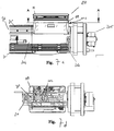
- Each shuttle (10) is mainly made up of two portions:
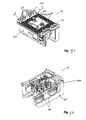
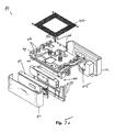
- the rail (20) integrates a continuous series of fixed permanent magnets (201) along its entire length and also integrates absolute reference means of the encoder type which can be used simultaneously by each shuttle (10, 110) and by the central server (2) which acts as a centralized logic unit of control and support of the system (1, 10, 103), for the purpose of instantaneous localization and adaptations ( Figs. 5-7 ).
- the invention provides a system of smart sensors, which interact both on a local level and on a global level, which consists of readers and proximity sensors mounted on the shuttle (10, 11) and a linear position transducer or linear encoder, which is fixed in a continuous way on the rail, along the entire path like a fixed and preferably absolute reference.
- each sliding shoe (11) also allowing each shuttle (10) active in the system (1) to know the position of the other shuttles; such a solution is particularly useful in case of maintenance, machine downtime or system re-setting and overcomes the known problems of the systems with encoders of the incremental type, which are substantially intended to detect the relative positioning from one point to another.
- said rail (20) advantageously integrates the means for the power supply of the shuttles and for data transmission.
- said shuttle (10) is basically a smart, autonomous drive motor module, that is to say, of the active type, having on board the electromagnetic coils (102) and all the necessary functions for operating in the integrated system (1), that is to say, only requiring power supply and connection for communication.
- said active module does not contain moving parts and is not subject to wear, it being substantially a mechatronic unit formed by a fully integrated linear synchronous motor, that is to say, including its own logic control unit and some means for the exact detection of position, of the absolute reference type. Therefore, the arrangement of the on-board supplied coils and the structural configuration of the shuttle allow to realize a ready-to-use handling unit, easy to be removed or added, which allows to optimize control electronics and reduce assembly costs.
- the measure of the translation of said active module is autonomous, each shuttle being provided with its own detector of a univocal and absolute reference along the entire rail, like the permanent magnets, that is to say, said rail being of the passive type. Therefore, for each shuttle added or replaced in the system, one can clearly see the advantage of not having to adjust, or calibrate or add any device or equipment for the purpose of control, the instantaneous detection of the position of the shuttle and also of the other connected shuttles being automatic. In this way, the system is always calibrated and tolerances are automatically compensated for.
- each shuttle is thus of the lightened type, that is to say, of less than 5000 g, and also the load-bearing structure consisting of the rail and of the respective supports is lightened and of compact size.
- the path of the shuttles is easily composable by joining in series straight and/or curved sections of rail and/or overturning means and/or rail switches.
- the rail comprises permanent magnets along its entire operational length, adapting in an optimal way to the configuration of said shuttles (10) thanks to the optimized geometrical shape and to the surface preferably of high-resistance anodized aluminium which houses the sliding linear guides for roller or ball bearings, housed on the shuttle, and enables rapid movements and without wear; in this way lubrication is not provided and is not necessary.
- the insertion or the removal of the single shuttle (10) in the rail (20) is particularly easy both on the main section of translation of the rail or on secondary sections of shunting and maintenance; the translation movement is rapid but gentle, that is to say, without sudden movements, the tolerances being minimum and the elements in contact being preloaded.
- the sliding shoe (11) engages and translates in the rail (20) thanks to the guides with preloaded rollers or balls, substantially acting as an idle bearing; in this way the wear is minimum because the loads and frictions are minimum.
- the motor, with on-board coils and fixed magnets on the rail, does not have parts in contact or moving parts, therefore the degree of wear is null.
- Said shuttle (10) integrates coils (102) which are selectively supplied in such a way as to generate the propulsive force absorbing from the rail (20) the forces of attraction provided by the permanent magnets (201), in particular maximizing the component parallel to the direction of travel of said force and compensating for the other components as much as possible, and thus with minimized loads, friction and wear of the rotating elements ( Fig. 7d ). It can be observed that also in the curved portions of the path such a solution has a high dynamics of movement without generating heat.
- the invention provides:
- the release of said tray (12) can be commanded by the shuttle (11) upon occurrence of given conditions or by the external control system or server (2).
- said means is of the equipped type (12) for the specific operation to be performed, to this purpose comprising, for example:
- said rail (20) comprises:
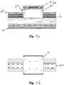
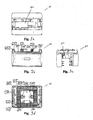
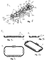
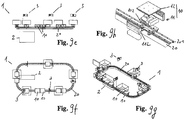
- the system (1) provides a linear and compact configuration of said rail (20) in the form of a vertical loop ( Figs. 6-8 ) with top-bottom rail and lateral overturning of the shuttles (10), whereas a comparative example not forming part of the invention provides a simple horizontal loop configuration in the form of a circuit ( Figs. 9a-h ).
- Said overturning occurs with an overturning means (205): the empty shuttle is overturned by 180° degrees (50c-d) by means of a device intended to overturn a whole section of rail (206), including guides, magnets and power supply system by a rotary motor with slip-rings for the control and the continuity of power supply.
- the control of rotation is performed with an encoder which provides high positioning precision, so as to allow the shuttle (10) to exit when the rotation has been completed and to take a new section of rectilinear rail (50b) placed at a lower level with respect to the forward one (50a), for the return of the shuttle to the initial loading station.
- Said overturning means (205) can also make partial rotations, for example of 90° degrees (50e) for making said shuttle (10) exit on a section of rail intended for particular purposes such as maintenance or other purposes ( Fig. 6 ).
- the whole integrated system (1) is coordinated by a centralized control system consisting of a central server (2) provided with programs which are intended to superintend overall management, it being able at least to:
- Such a configuration of the system (1) and shuttles (10) can also easily include special shuttles, that is to say, intended to perform diversified missions, with particular and different purposes with respect to the other shuttles but with the same movement and interaction logic.
- Said system (1) is suitable for the automated machining of flat semi-finished products, or non-flat semi-finished products held by suitable grippers or anchorage tools controlled by holding or release drives (104) on the shuttle itself.
- the mover or self-propelled sliding shoe (11) with moving coils is equipped with on-board intelligence (103) which provides management autonomy, even when coordinated by a central control system, and the movement of controlled axes on the mover and supplementary to the motion control of the advancement on the rail.
- Such a solution allows to manage interstation operations in a production plant with workstations, in a non-synchronous way as well, if necessary during the movement or the wait before reaching a station as it happens, for example, in the case in which one provides the lifting or the inclination of working surfaces or trays (12), or also if there is the translation and/or rotation of operating axes (104) on the shuttle, with the possible activation of pressure or vacuum on board (105, 106). It has been observed that these possible system features nowadays are impossible to be obtained by means of the systems with shuttles of the moving magnets type, or inexistent in the known systems or anyway very expensive to make.
- the present invention optimizes and integrates the motion system and the system of accessory axes, rendering the shuttle sometimes master and sometimes slave depending on the particular requirements and situations.
Landscapes
- Engineering & Computer Science (AREA)
- Mechanical Engineering (AREA)
- Non-Mechanical Conveyors (AREA)
- Control Of Conveyors (AREA)
- Automatic Assembly (AREA)
- Control Of Position, Course, Altitude, Or Attitude Of Moving Bodies (AREA)
- Automobile Manufacture Line, Endless Track Vehicle, Trailer (AREA)
Priority Applications (4)
| Application Number | Priority Date | Filing Date | Title |
|---|---|---|---|
| RS20210454A RS61776B1 (sr) | 2016-02-29 | 2017-02-28 | Sistem za rukovanje nezavisnim i koordinisanim transporterom, za industrijsku automatizaciju |
| PL17716589T PL3424075T3 (pl) | 2016-02-29 | 2017-02-28 | System transportowy z niezależnym i skoordynowanym wózkiem dla automatyki przemysłowej |
| HRP20210622TT HRP20210622T1 (hr) | 2016-02-29 | 2017-02-28 | Sustav za rukovanje neovisnim i koordiniranim šatlom, za industrijsku automatizaciju |
| SI201730723T SI3424075T1 (sl) | 2016-02-29 | 2017-02-28 | Manipulacijski sistem z neodvisnim in koordiniranim čolničkom za industrijsko avtomatiko |
Applications Claiming Priority (2)
| Application Number | Priority Date | Filing Date | Title |
|---|---|---|---|
| ITUB2016A001148A ITUB20161148A1 (it) | 2016-02-29 | 2016-02-29 | Sistema di movimentazione a navette indipendenti e coordinate, per automazione industriale |
| PCT/IB2017/000184 WO2017149377A1 (en) | 2016-02-29 | 2017-02-28 | Handling system with independent and coordinated shuttle, for industrial automation |
Publications (2)
| Publication Number | Publication Date |
|---|---|
| EP3424075A1 EP3424075A1 (en) | 2019-01-09 |
| EP3424075B1 true EP3424075B1 (en) | 2021-01-20 |
Family
ID=56134492
Family Applications (1)
| Application Number | Title | Priority Date | Filing Date |
|---|---|---|---|
| EP17716589.1A Active EP3424075B1 (en) | 2016-02-29 | 2017-02-28 | Handling system with independent and coordinated shuttle, for industrial automation |
Country Status (14)
| Country | Link |
|---|---|
| US (1) | US10308446B2 (pl) |
| EP (1) | EP3424075B1 (pl) |
| CN (1) | CN108701637B (pl) |
| DK (1) | DK3424075T3 (pl) |
| ES (1) | ES2865497T3 (pl) |
| HR (1) | HRP20210622T1 (pl) |
| HU (1) | HUE054200T2 (pl) |
| IT (1) | ITUB20161148A1 (pl) |
| LT (1) | LT3424075T (pl) |
| PL (1) | PL3424075T3 (pl) |
| PT (1) | PT3424075T (pl) |
| RS (1) | RS61776B1 (pl) |
| SI (1) | SI3424075T1 (pl) |
| WO (1) | WO2017149377A1 (pl) |
Cited By (2)
| Publication number | Priority date | Publication date | Assignee | Title |
|---|---|---|---|---|
| WO2023018734A1 (en) * | 2021-08-13 | 2023-02-16 | House of Design LLC | Conveyor system |
| DE102024130368B3 (de) | 2024-10-18 | 2026-03-26 | Mb Automation Gmbh & Co. Kg | Montagelinie und Verfahren zur Herstellung von Modulen oder Vorstufen von Modulen |
Families Citing this family (46)
| Publication number | Priority date | Publication date | Assignee | Title |
|---|---|---|---|---|
| EP3173887A1 (de) * | 2015-11-24 | 2017-05-31 | Siemens Aktiengesellschaft | Verfahren zur bewegung eines läufers, linearantrieb und produktion- oder verpackungsmaschine |
| ITUB20161142A1 (it) * | 2016-02-29 | 2017-08-29 | Vismunda Srl | Metodo e impianto produttivo automatico per la stampa su celle fotovoltaiche. |
| US11220081B2 (en) * | 2016-05-16 | 2022-01-11 | Cmd Corporation | Method and apparatus for pouch or bag making |
| US10996232B2 (en) | 2016-09-09 | 2021-05-04 | The Procter & Gamble Company | System and method for independently routing container-loaded vehicles to create different finished products |
| MX2019002782A (es) | 2016-09-09 | 2019-09-04 | Procter & Gamble | Sistema y método para llenar simultáneamente recipientes con diferentes composiciones de fluidos. |
| WO2018049121A2 (en) | 2016-09-09 | 2018-03-15 | The Procter & Gamble Company | System and method for producing products based upon demand |
| MX2019002780A (es) | 2016-09-09 | 2019-09-04 | Procter & Gamble | Sistema y método para llenar simultáneamente recipientes de formas y/o tamaños diferentes. |
| CN109661361B (zh) | 2016-09-09 | 2021-11-19 | 宝洁公司 | 用于创建成品的轨道系统 |
| CN109661623A (zh) | 2016-09-09 | 2019-04-19 | 宝洁公司 | 用于在单条生产线上同时生产不同产品的方法 |
| EP4194378B1 (en) | 2016-09-09 | 2024-11-20 | The Procter & Gamble Company | System and method for independently routing vehicles and delivering containers and closures to unit operation stations |
| US10479609B2 (en) * | 2017-06-08 | 2019-11-19 | Khs Usa, Inc. | Conveyor system with selective carriage vacuum supply |
| DE102017223078A1 (de) * | 2017-12-18 | 2019-06-19 | Krones Ag | Vorrichtung zum Behandeln von Behältern |
| US10934099B2 (en) * | 2018-05-02 | 2021-03-02 | Caromation, Inc. | Electric pallet conveyor |
| DE102018111715A1 (de) | 2018-05-16 | 2019-11-21 | Beckhoff Automation Gmbh | Lineares transportsystem und system zur kontaktlosen energie- und datenübertragung |
| IT201800007365A1 (it) * | 2018-07-20 | 2020-01-20 | Sistema di trasporto per il trasporto di prodotti | |
| CN109368167B (zh) * | 2018-10-25 | 2023-11-14 | 东风设计研究院有限公司 | 一种滑橇式连续供电、通讯多功能升降滑板输送系统 |
| US10967892B2 (en) * | 2018-11-08 | 2021-04-06 | Rockwell Automation Technologies, Inc. | Independent cart system and method of operating the same |
| DE102019100177B4 (de) * | 2019-01-07 | 2022-05-05 | Boehm Systems Engineering GmbH | Modulares und transportables Transportsystem |
| IT201900003895A1 (it) * | 2019-03-18 | 2020-09-18 | Cft Spa | Apparato di trasporto |
| DE102019002424A1 (de) * | 2019-04-03 | 2020-10-08 | Günther Zimmer | Umsetzvorrichtung eines Transportsystems |
| US11724894B2 (en) * | 2019-04-16 | 2023-08-15 | Yamaha Hatsudoki Kabushiki Kaisha | Linear conveyor system, a control method for a linear conveyor system, a control program for a linear conveyor system and a recording medium |
| CN111846805B (zh) * | 2019-04-30 | 2024-06-14 | 湖南工业大学 | 一种自翻转循环小车物料输送系统 |
| US11027628B2 (en) * | 2019-05-02 | 2021-06-08 | Ford Global Technologies, Llc | Vehicle having rail-mounted components |
| BR112021023414A2 (pt) * | 2019-05-21 | 2022-02-01 | Westrock Packaging Systems Llc | Sistema de medição de produto de passo flexível |
| DE102019118442A1 (de) * | 2019-07-08 | 2021-01-14 | Schunk Electronic Solutions Gmbh | Verfahren zur Bestimmung der Absolutposition eines Schlittens eines elektrischen Lineardirektantriebs und elektrischer Lineardirektantrieb |
| DE102019007764B4 (de) * | 2019-11-10 | 2022-05-12 | Günther Zimmer | Werkstückwagen sowie Werkzeugmaschine und Fertigungszelle mit derartigem Werkstückwagen |
| CN111153134B (zh) * | 2020-01-15 | 2024-05-14 | 深圳市罗博威视科技有限公司 | 一种分盘扫码设备 |
| DE102020110795A1 (de) * | 2020-04-21 | 2021-10-21 | Beckhoff Automation Gmbh | Anschalteinheit in einem linearen Transportsystem |
| CN111762523B (zh) * | 2020-07-01 | 2025-03-14 | 北京首钢国际工程技术有限公司 | 一种卷取区域钢卷输送系统 |
| CN111776645A (zh) * | 2020-07-24 | 2020-10-16 | 苏州天准科技股份有限公司 | 一种多工位的取放料装置 |
| EP3960668B1 (de) * | 2020-08-28 | 2025-10-01 | Schneider Electric Industries SAS | Linearmotorsystem und verfahren zum betreiben eines solchen |
| IT202000023242A1 (it) * | 2020-10-02 | 2022-04-02 | Giona Donadon | Dispositivo autonomo per il posizionamento con micro motori di supporti per il filo da taglio a caldo di polistirolo e/o schiume |
| CN112978275B (zh) * | 2021-02-24 | 2022-06-24 | 东莞市超业精密设备有限公司 | 一种除尘输送和自定位一体的输送设备 |
| CN112875212A (zh) * | 2021-03-18 | 2021-06-01 | 苏州市华创力自动化科技有限公司 | 一种轨道式液体输送系统的稳控装置 |
| JP7636232B2 (ja) * | 2021-03-29 | 2025-02-26 | 株式会社京都製作所 | リニア搬送装置及びリニア搬送装置の制御方法 |
| CN113359632B (zh) * | 2021-06-09 | 2023-11-07 | 江苏徐工工程机械研究院有限公司 | 多工序物料输运系统及控制方法 |
| CN113419435B (zh) * | 2021-06-21 | 2022-06-28 | 大工科技(上海)有限公司 | 一种智能传输平台交互系统 |
| CN113682751B (zh) * | 2021-08-11 | 2023-12-15 | 弥费实业(上海)有限公司 | 一种空中搬运装置及搬运系统 |
| US11590849B1 (en) * | 2021-08-17 | 2023-02-28 | Amazon Technologies, Inc. | Wireless powering and control of conveyors on shuttles |
| CN114291119B (zh) * | 2022-03-09 | 2022-05-13 | 徐州徐工传动科技有限公司 | 一种自适应的重载齿轮传动行走装置 |
| JP2023180543A (ja) * | 2022-06-09 | 2023-12-21 | 澁谷工業株式会社 | 物品搬送装置 |
| DE102023000658A1 (de) * | 2023-02-23 | 2024-08-29 | Emhs Gmbh | Kollisionsvermeidung bei einem mit zumindest teilautonom fahrenden Hängetaschen ausgestatteten Hängetaschenlager |
| IT202300007893A1 (it) * | 2023-04-21 | 2024-10-21 | G Mondini S P A | Apparecchiatura per il trasporto di oggetti |
| TWI856688B (zh) * | 2023-06-01 | 2024-09-21 | 鴻勁精密股份有限公司 | 電子元件翻料機構、作業裝置及作業機 |
| CN119016386B (zh) * | 2024-09-26 | 2025-04-01 | 东莞市英博五金制品有限公司 | 一种玩具自动组装检测方法及装置 |
| CN120288443B (zh) * | 2025-06-03 | 2025-12-12 | 上海中商网络股份有限公司 | 一种基于产品长度的分料方法、系统及存储介质 |
Family Cites Families (13)
| Publication number | Priority date | Publication date | Assignee | Title |
|---|---|---|---|---|
| JP2000286318A (ja) * | 1999-01-27 | 2000-10-13 | Shinko Electric Co Ltd | 搬送システム |
| JP3793013B2 (ja) * | 2000-09-29 | 2006-07-05 | 住友重機械工業株式会社 | 磁気浮上移動装置 |
| KR20070011577A (ko) * | 2004-05-07 | 2007-01-24 | 마그네모션, 인코포레이티드 | 단일 경로를 기반으로 하는 작용기들을 이용한 3차원 동작 |
| US7677180B2 (en) * | 2005-06-09 | 2010-03-16 | International Business Machines Corporation | Apparatus and method for steering transport vehicles in semiconductor processing |
| US8616134B2 (en) * | 2009-01-23 | 2013-12-31 | Magnemotion, Inc. | Transport system powered by short block linear synchronous motors |
| ITTO20090773A1 (it) * | 2009-10-09 | 2011-04-10 | Icam S R L | Navetta di un magazzino automatizzato, e metodo di controllo per guidare tale navetta |
| JP5333537B2 (ja) * | 2011-07-22 | 2013-11-06 | 村田機械株式会社 | 移動体システムと移動体の走行制御方法 |
| KR102013970B1 (ko) * | 2011-09-30 | 2019-08-23 | 에이티에스 오토메이션 툴링 시스템즈 인코포레이티드 | 이동 요소에 진공을 제공하는 시스템 및 방법 |
| EP2810185B1 (en) * | 2012-02-03 | 2019-05-15 | Siemens Healthcare Diagnostics Inc. | Power source for an automation system mechanism |
| JP6098923B2 (ja) * | 2012-12-27 | 2017-03-22 | シンフォニアテクノロジー株式会社 | 搬送装置 |
| JP6094331B2 (ja) * | 2013-03-29 | 2017-03-15 | 株式会社ダイフク | 物品搬送設備 |
| EP4410717A3 (en) * | 2013-07-29 | 2025-03-05 | Ats Corporation | Magnetic element for thrust and bearing |
| JP2017048018A (ja) * | 2015-09-02 | 2017-03-09 | 株式会社東芝 | 物品仕分装置 |
-
2016
- 2016-02-29 IT ITUB2016A001148A patent/ITUB20161148A1/it unknown
-
2017
- 2017-02-28 EP EP17716589.1A patent/EP3424075B1/en active Active
- 2017-02-28 LT LTEP17716589.1T patent/LT3424075T/lt unknown
- 2017-02-28 PT PT177165891T patent/PT3424075T/pt unknown
- 2017-02-28 PL PL17716589T patent/PL3424075T3/pl unknown
- 2017-02-28 HR HRP20210622TT patent/HRP20210622T1/hr unknown
- 2017-02-28 WO PCT/IB2017/000184 patent/WO2017149377A1/en not_active Ceased
- 2017-02-28 ES ES17716589T patent/ES2865497T3/es active Active
- 2017-02-28 HU HUE17716589A patent/HUE054200T2/hu unknown
- 2017-02-28 US US16/076,893 patent/US10308446B2/en active Active
- 2017-02-28 CN CN201780014206.1A patent/CN108701637B/zh active Active
- 2017-02-28 SI SI201730723T patent/SI3424075T1/sl unknown
- 2017-02-28 RS RS20210454A patent/RS61776B1/sr unknown
- 2017-02-28 DK DK17716589.1T patent/DK3424075T3/da active
Non-Patent Citations (1)
| Title |
|---|
| None * |
Cited By (2)
| Publication number | Priority date | Publication date | Assignee | Title |
|---|---|---|---|---|
| WO2023018734A1 (en) * | 2021-08-13 | 2023-02-16 | House of Design LLC | Conveyor system |
| DE102024130368B3 (de) | 2024-10-18 | 2026-03-26 | Mb Automation Gmbh & Co. Kg | Montagelinie und Verfahren zur Herstellung von Modulen oder Vorstufen von Modulen |
Also Published As
| Publication number | Publication date |
|---|---|
| ITUB20161148A1 (it) | 2017-08-29 |
| CN108701637A (zh) | 2018-10-23 |
| LT3424075T (lt) | 2021-05-10 |
| US10308446B2 (en) | 2019-06-04 |
| US20190047799A1 (en) | 2019-02-14 |
| DK3424075T3 (da) | 2021-04-19 |
| EP3424075A1 (en) | 2019-01-09 |
| RS61776B1 (sr) | 2021-06-30 |
| ES2865497T3 (es) | 2021-10-15 |
| WO2017149377A1 (en) | 2017-09-08 |
| HRP20210622T1 (hr) | 2021-07-09 |
| PL3424075T3 (pl) | 2021-07-12 |
| PT3424075T (pt) | 2021-04-27 |
| CN108701637B (zh) | 2024-03-05 |
| SI3424075T1 (sl) | 2021-08-31 |
| HUE054200T2 (hu) | 2021-08-30 |
Similar Documents
| Publication | Publication Date | Title |
|---|---|---|
| EP3424075B1 (en) | Handling system with independent and coordinated shuttle, for industrial automation | |
| EP3424084B1 (en) | Method and automatic production plant for printing on photovoltaic cells | |
| EP2403784B1 (en) | Multi-mode scroll cam conveyor system | |
| CN115241781B (zh) | 一种控制柜或电气柜背板装配生产线及其装配工艺 | |
| CN119976150A (zh) | 一种贯穿堆垛机巷道的输送装置 | |
| JP4446936B2 (ja) | パレット搬送方法及び装置 | |
| TW202011627A (zh) | 用於在光伏電池上印刷的方法和自動生產設備 | |
| CN213445154U (zh) | 一种视觉引导四自由度拆码垛机器人 | |
| CN220906243U (zh) | 转运设备和测试系统 | |
| TWM638450U (zh) | 用於工業自動化的具有獨立的協調梭車的操縱系統 | |
| TW202011504A (zh) | 用於工業自動化的具有獨立的協調梭車的操縱系統 | |
| CN214166545U (zh) | 下料托盘装置 | |
| CN219822705U (zh) | 一种环形传送装置 | |
| KR101116600B1 (ko) | 이차원 이송장치 | |
| CN223457546U (zh) | 治具传输装置以及物料加工设备 | |
| CN113369845B (zh) | 物料生产装配线 | |
| TWM638428U (zh) | 用於在光伏電池上印刷的自動生產設備 | |
| CN116835246A (zh) | 输送装置 | |
| CN117401373A (zh) | 转运设备和测试系统 | |
| CN113636325A (zh) | 内存条插件供料装置 |
Legal Events
| Date | Code | Title | Description |
|---|---|---|---|
| STAA | Information on the status of an ep patent application or granted ep patent |
Free format text: STATUS: UNKNOWN |
|
| STAA | Information on the status of an ep patent application or granted ep patent |
Free format text: STATUS: THE INTERNATIONAL PUBLICATION HAS BEEN MADE |
|
| PUAI | Public reference made under article 153(3) epc to a published international application that has entered the european phase |
Free format text: ORIGINAL CODE: 0009012 |
|
| STAA | Information on the status of an ep patent application or granted ep patent |
Free format text: STATUS: REQUEST FOR EXAMINATION WAS MADE |
|
| 17P | Request for examination filed |
Effective date: 20180830 |
|
| AK | Designated contracting states |
Kind code of ref document: A1 Designated state(s): AL AT BE BG CH CY CZ DE DK EE ES FI FR GB GR HR HU IE IS IT LI LT LU LV MC MK MT NL NO PL PT RO RS SE SI SK SM TR |
|
| AX | Request for extension of the european patent |
Extension state: BA ME |
|
| DAV | Request for validation of the european patent (deleted) | ||
| DAX | Request for extension of the european patent (deleted) | ||
| GRAP | Despatch of communication of intention to grant a patent |
Free format text: ORIGINAL CODE: EPIDOSNIGR1 |
|
| STAA | Information on the status of an ep patent application or granted ep patent |
Free format text: STATUS: GRANT OF PATENT IS INTENDED |
|
| INTG | Intention to grant announced |
Effective date: 20200122 |
|
| GRAS | Grant fee paid |
Free format text: ORIGINAL CODE: EPIDOSNIGR3 |
|
| GRAF | Information related to payment of grant fee modified |
Free format text: ORIGINAL CODE: EPIDOSCIGR3 |
|
| GRAA | (expected) grant |
Free format text: ORIGINAL CODE: 0009210 |
|
| STAA | Information on the status of an ep patent application or granted ep patent |
Free format text: STATUS: THE PATENT HAS BEEN GRANTED |
|
| AK | Designated contracting states |
Kind code of ref document: B1 Designated state(s): AL AT BE BG CH CY CZ DE DK EE ES FI FR GB GR HR HU IE IS IT LI LT LU LV MC MK MT NL NO PL PT RO RS SE SI SK SM TR |
|
| REG | Reference to a national code |
Ref country code: GB Ref legal event code: FG4D |
|
| REG | Reference to a national code |
Ref country code: CH Ref legal event code: EP |
|
| REG | Reference to a national code |
Ref country code: AT Ref legal event code: REF Ref document number: 1357112 Country of ref document: AT Kind code of ref document: T Effective date: 20210215 |
|
| REG | Reference to a national code |
Ref country code: IE Ref legal event code: FG4D |
|
| REG | Reference to a national code |
Ref country code: DE Ref legal event code: R096 Ref document number: 602017031640 Country of ref document: DE |
|
| REG | Reference to a national code |
Ref country code: FI Ref legal event code: FGE |
|
| REG | Reference to a national code |
Ref country code: HR Ref legal event code: TUEP Ref document number: P20210622T Country of ref document: HR Ref country code: DK Ref legal event code: T3 Effective date: 20210415 Ref country code: RO Ref legal event code: EPE |
|
| REG | Reference to a national code |
Ref country code: NL Ref legal event code: FP |
|
| REG | Reference to a national code |
Ref country code: PT Ref legal event code: SC4A Ref document number: 3424075 Country of ref document: PT Date of ref document: 20210427 Kind code of ref document: T Free format text: AVAILABILITY OF NATIONAL TRANSLATION Effective date: 20210420 |
|
| REG | Reference to a national code |
Ref country code: NO Ref legal event code: T2 Effective date: 20210120 |
|
| REG | Reference to a national code |
Ref country code: SE Ref legal event code: TRGR |
|
| REG | Reference to a national code |
Ref country code: HR Ref legal event code: ODRP Ref document number: P20210622T Country of ref document: HR Payment date: 20210419 Year of fee payment: 5 |
|
| REG | Reference to a national code |
Ref country code: EE Ref legal event code: FG4A Ref document number: E020774 Country of ref document: EE Effective date: 20210415 |
|
| REG | Reference to a national code |
Ref country code: SK Ref legal event code: T3 Ref document number: E 37123 Country of ref document: SK |
|
| REG | Reference to a national code |
Ref country code: HR Ref legal event code: T1PR Ref document number: P20210622 Country of ref document: HR |
|
| PG25 | Lapsed in a contracting state [announced via postgrant information from national office to epo] |
Ref country code: GR Free format text: LAPSE BECAUSE OF FAILURE TO SUBMIT A TRANSLATION OF THE DESCRIPTION OR TO PAY THE FEE WITHIN THE PRESCRIBED TIME-LIMIT Effective date: 20210421 |
|
| REG | Reference to a national code |
Ref country code: HU Ref legal event code: AG4A Ref document number: E054200 Country of ref document: HU |
|
| PG25 | Lapsed in a contracting state [announced via postgrant information from national office to epo] |
Ref country code: LV Free format text: LAPSE BECAUSE OF FAILURE TO SUBMIT A TRANSLATION OF THE DESCRIPTION OR TO PAY THE FEE WITHIN THE PRESCRIBED TIME-LIMIT Effective date: 20210120 |
|
| REG | Reference to a national code |
Ref country code: ES Ref legal event code: FG2A Ref document number: 2865497 Country of ref document: ES Kind code of ref document: T3 Effective date: 20211015 |
|
| REG | Reference to a national code |
Ref country code: DE Ref legal event code: R097 Ref document number: 602017031640 Country of ref document: DE |
|
| PG25 | Lapsed in a contracting state [announced via postgrant information from national office to epo] |
Ref country code: SM Free format text: LAPSE BECAUSE OF FAILURE TO SUBMIT A TRANSLATION OF THE DESCRIPTION OR TO PAY THE FEE WITHIN THE PRESCRIBED TIME-LIMIT Effective date: 20210120 |
|
| PLBE | No opposition filed within time limit |
Free format text: ORIGINAL CODE: 0009261 |
|
| STAA | Information on the status of an ep patent application or granted ep patent |
Free format text: STATUS: NO OPPOSITION FILED WITHIN TIME LIMIT |
|
| 26N | No opposition filed |
Effective date: 20211021 |
|
| REG | Reference to a national code |
Ref country code: SI Ref legal event code: KO00 Effective date: 20211125 |
|
| PG25 | Lapsed in a contracting state [announced via postgrant information from national office to epo] |
Ref country code: AL Free format text: LAPSE BECAUSE OF FAILURE TO SUBMIT A TRANSLATION OF THE DESCRIPTION OR TO PAY THE FEE WITHIN THE PRESCRIBED TIME-LIMIT Effective date: 20210120 |
|
| PG25 | Lapsed in a contracting state [announced via postgrant information from national office to epo] |
Ref country code: SI Free format text: LAPSE BECAUSE OF NON-PAYMENT OF DUE FEES Effective date: 20210301 |
|
| REG | Reference to a national code |
Ref country code: HR Ref legal event code: ODRP Ref document number: P20210622 Country of ref document: HR Payment date: 20220222 Year of fee payment: 6 |
|
| REG | Reference to a national code |
Ref country code: AT Ref legal event code: UEP Ref document number: 1357112 Country of ref document: AT Kind code of ref document: T Effective date: 20210120 |
|
| REG | Reference to a national code |
Ref country code: HR Ref legal event code: ODRP Ref document number: P20210622 Country of ref document: HR Payment date: 20230227 Year of fee payment: 7 |
|
| PGFP | Annual fee paid to national office [announced via postgrant information from national office to epo] |
Ref country code: MC Payment date: 20230301 Year of fee payment: 7 Ref country code: LT Payment date: 20230227 Year of fee payment: 7 |
|
| PGFP | Annual fee paid to national office [announced via postgrant information from national office to epo] |
Ref country code: IS Payment date: 20230227 Year of fee payment: 8 Ref country code: EE Payment date: 20230227 Year of fee payment: 7 |
|
| PG25 | Lapsed in a contracting state [announced via postgrant information from national office to epo] |
Ref country code: CY Free format text: LAPSE BECAUSE OF FAILURE TO SUBMIT A TRANSLATION OF THE DESCRIPTION OR TO PAY THE FEE WITHIN THE PRESCRIBED TIME-LIMIT Effective date: 20210120 |
|
| PG25 | Lapsed in a contracting state [announced via postgrant information from national office to epo] |
Ref country code: BG Free format text: LAPSE BECAUSE OF NON-PAYMENT OF DUE FEES Effective date: 20210401 |
|
| REG | Reference to a national code |
Ref country code: HR Ref legal event code: ODRP Ref document number: P20210622 Country of ref document: HR Payment date: 20240223 Year of fee payment: 8 |
|
| PG25 | Lapsed in a contracting state [announced via postgrant information from national office to epo] |
Ref country code: MK Free format text: LAPSE BECAUSE OF FAILURE TO SUBMIT A TRANSLATION OF THE DESCRIPTION OR TO PAY THE FEE WITHIN THE PRESCRIBED TIME-LIMIT Effective date: 20210120 |
|
| P01 | Opt-out of the competence of the unified patent court (upc) registered |
Effective date: 20240502 |
|
| REG | Reference to a national code |
Ref country code: EE Ref legal event code: MM4A Ref document number: E020774 Country of ref document: EE Effective date: 20240229 |
|
| REG | Reference to a national code |
Ref country code: LT Ref legal event code: MM4D Effective date: 20240228 |
|
| PG25 | Lapsed in a contracting state [announced via postgrant information from national office to epo] |
Ref country code: MT Free format text: LAPSE BECAUSE OF FAILURE TO SUBMIT A TRANSLATION OF THE DESCRIPTION OR TO PAY THE FEE WITHIN THE PRESCRIBED TIME-LIMIT Effective date: 20210120 Ref country code: MC Free format text: LAPSE BECAUSE OF NON-PAYMENT OF DUE FEES Effective date: 20240229 |
|
| PG25 | Lapsed in a contracting state [announced via postgrant information from national office to epo] |
Ref country code: LT Free format text: LAPSE BECAUSE OF NON-PAYMENT OF DUE FEES Effective date: 20240228 |
|
| PG25 | Lapsed in a contracting state [announced via postgrant information from national office to epo] |
Ref country code: EE Free format text: LAPSE BECAUSE OF NON-PAYMENT OF DUE FEES Effective date: 20240229 |
|
| PG25 | Lapsed in a contracting state [announced via postgrant information from national office to epo] |
Ref country code: LT Free format text: LAPSE BECAUSE OF NON-PAYMENT OF DUE FEES Effective date: 20240228 Ref country code: EE Free format text: LAPSE BECAUSE OF NON-PAYMENT OF DUE FEES Effective date: 20240229 |
|
| REG | Reference to a national code |
Ref country code: HR Ref legal event code: ODRP Ref document number: P20210622 Country of ref document: HR Payment date: 20250224 Year of fee payment: 9 |
|
| PGFP | Annual fee paid to national office [announced via postgrant information from national office to epo] |
Ref country code: PT Payment date: 20250225 Year of fee payment: 9 |
|
| PGFP | Annual fee paid to national office [announced via postgrant information from national office to epo] |
Ref country code: BG Payment date: 20250226 Year of fee payment: 10 |
|
| PGFP | Annual fee paid to national office [announced via postgrant information from national office to epo] |
Ref country code: CH Payment date: 20250301 Year of fee payment: 9 Ref country code: SI Payment date: 20250225 Year of fee payment: 9 |
|
| PGFP | Annual fee paid to national office [announced via postgrant information from national office to epo] |
Ref country code: PL Payment date: 20250224 Year of fee payment: 9 Ref country code: CZ Payment date: 20250226 Year of fee payment: 9 |
|
| PGFP | Annual fee paid to national office [announced via postgrant information from national office to epo] |
Ref country code: SK Payment date: 20250225 Year of fee payment: 9 |
|
| PG25 | Lapsed in a contracting state [announced via postgrant information from national office to epo] |
Ref country code: EE Free format text: LAPSE BECAUSE OF NON-PAYMENT OF DUE FEES Effective date: 20210228 |
|
| PG25 | Lapsed in a contracting state [announced via postgrant information from national office to epo] |
Ref country code: IS Free format text: LAPSE BECAUSE OF NON-PAYMENT OF DUE FEES Effective date: 20240905 |
|
| REG | Reference to a national code |
Ref country code: DE Ref legal event code: R079 Ref document number: 602017031640 Country of ref document: DE Free format text: PREVIOUS MAIN CLASS: H01L0021677000 Ipc: H10P0072300000 |
|
| REG | Reference to a national code |
Ref country code: CH Ref legal event code: U11 Free format text: ST27 STATUS EVENT CODE: U-0-0-U10-U11 (AS PROVIDED BY THE NATIONAL OFFICE) Effective date: 20260301 |
|
| PG2D | Information on lapse in contracting state deleted |
Ref country code: BG |
|
| PGFP | Annual fee paid to national office [announced via postgrant information from national office to epo] |
Ref country code: LU Payment date: 20260227 Year of fee payment: 10 Ref country code: NL Payment date: 20260226 Year of fee payment: 10 |
|
| REG | Reference to a national code |
Ref country code: HR Ref legal event code: ODRP Ref document number: P20210622 Country of ref document: HR Payment date: 20260226 Year of fee payment: 10 |
|
| PGFP | Annual fee paid to national office [announced via postgrant information from national office to epo] |
Ref country code: SE Payment date: 20260226 Year of fee payment: 10 |
|
| PGFP | Annual fee paid to national office [announced via postgrant information from national office to epo] |
Ref country code: GB Payment date: 20260227 Year of fee payment: 10 |
|
| PGFP | Annual fee paid to national office [announced via postgrant information from national office to epo] |
Ref country code: ES Payment date: 20260304 Year of fee payment: 10 |
|
| PGFP | Annual fee paid to national office [announced via postgrant information from national office to epo] |
Ref country code: DE Payment date: 20260301 Year of fee payment: 10 Ref country code: NO Payment date: 20260227 Year of fee payment: 10 Ref country code: DK Payment date: 20260325 Year of fee payment: 10 Ref country code: IE Payment date: 20260225 Year of fee payment: 10 |
|
| PGFP | Annual fee paid to national office [announced via postgrant information from national office to epo] |
Ref country code: HR Payment date: 20260226 Year of fee payment: 10 Ref country code: AT Payment date: 20260302 Year of fee payment: 10 |
|
| PGFP | Annual fee paid to national office [announced via postgrant information from national office to epo] |
Ref country code: RO Payment date: 20260227 Year of fee payment: 10 Ref country code: FI Payment date: 20260226 Year of fee payment: 10 Ref country code: IT Payment date: 20260225 Year of fee payment: 10 Ref country code: BE Payment date: 20260226 Year of fee payment: 10 |
|
| PGFP | Annual fee paid to national office [announced via postgrant information from national office to epo] |
Ref country code: HU Payment date: 20260305 Year of fee payment: 10 |
|
| PGFP | Annual fee paid to national office [announced via postgrant information from national office to epo] |
Ref country code: RS Payment date: 20260225 Year of fee payment: 10 |
|
| PGFP | Annual fee paid to national office [announced via postgrant information from national office to epo] |
Ref country code: FR Payment date: 20260227 Year of fee payment: 10 |
|
| PGFP | Annual fee paid to national office [announced via postgrant information from national office to epo] |
Ref country code: TR Payment date: 20260225 Year of fee payment: 10 |