EP3420793A1 - Vorrichtung zur einstellung der position eines holms eines ortsbeweglichen geräts - Google Patents
Vorrichtung zur einstellung der position eines holms eines ortsbeweglichen geräts Download PDFInfo
- Publication number
- EP3420793A1 EP3420793A1 EP18179430.6A EP18179430A EP3420793A1 EP 3420793 A1 EP3420793 A1 EP 3420793A1 EP 18179430 A EP18179430 A EP 18179430A EP 3420793 A1 EP3420793 A1 EP 3420793A1
- Authority
- EP
- European Patent Office
- Prior art keywords
- rotation
- axis
- spar
- locking
- notches
- Prior art date
- Legal status (The legal status is an assumption and is not a legal conclusion. Google has not performed a legal analysis and makes no representation as to the accuracy of the status listed.)
- Granted
Links
Images



Classifications
-
- A—HUMAN NECESSITIES
- A01—AGRICULTURE; FORESTRY; ANIMAL HUSBANDRY; HUNTING; TRAPPING; FISHING
- A01D—HARVESTING; MOWING
- A01D34/00—Mowers; Mowing apparatus of harvesters
- A01D34/01—Mowers; Mowing apparatus of harvesters characterised by features relating to the type of cutting apparatus
- A01D34/412—Mowers; Mowing apparatus of harvesters characterised by features relating to the type of cutting apparatus having rotating cutters
- A01D34/63—Mowers; Mowing apparatus of harvesters characterised by features relating to the type of cutting apparatus having rotating cutters having cutters rotating about a vertical axis
- A01D34/82—Other details
- A01D34/824—Handle arrangements
-
- B—PERFORMING OPERATIONS; TRANSPORTING
- B62—LAND VEHICLES FOR TRAVELLING OTHERWISE THAN ON RAILS
- B62B—HAND-PROPELLED VEHICLES, e.g. HAND CARTS OR PERAMBULATORS; SLEDGES
- B62B5/00—Accessories or details specially adapted for hand carts
- B62B5/06—Hand moving equipment, e.g. handle bars
- B62B5/064—Hand moving equipment, e.g. handle bars adaptable for different users, e.g. by means of pivoting elements
Definitions
- the invention relates to a device for adjusting the position of a spar for moving and / or controlling a portable device, wherein the spar has at least one spar bar whose first end is rotatably mounted on one end of the device and the second end carries a handle ,
- the device comprises a spar-adjusting mechanism, via which the first end of the spar is rotatable about a first axis of rotation and adjustable to a plurality of pivot positions on the device, and the locking means for fixing the spar in at least one pivot position.
- Such devices are used on a variety of devices, such as lawn mowers, scarifiers, other tillage implements, and other devices.
- the spar it is most desirable for the spar to be adjustable to different heights in order to allow adaptation to the size of the user and / or his preferences.
- a problem that occurs in such devices for adjusting the position of the spar is that the adjustment of the spar is made to different heights either by screw or the like, so that the position of the spar is difficult to change using tools, or it locking devices are used, but they are usually not backlash, which is disturbing in use.
- a device of the type mentioned is known in which the tie rod is extended by a plate-shaped projection having a cranked shape which extends laterally from the longitudinal axis of the tie rod and carries a locking pin, which can be brought into engagement with a latching recess in a detent plate is, which is pivotable about an axis parallel to the axis of rotation of the spar axis, wherein the locking devices are relatively complicated and have a considerable width, which is not readily covered by a cover, so that can catch caught in the locking mechanism grass and dirt.
- Covers for devices of the type mentioned are for example from the EP 3141101 A1 known.
- the invention has for its object to provide a device for adjusting the position of a spar, which is very easy to use and without tools and yet largely or completely free of play.
- FIG. 1 is an application example of an embodiment of the invention Holm adjustment shown, which is intended to illustrate where and at which point this embodiment of the handlebar adjustment mechanism in a lawnmower or similar garden and other devices 20 is usable.
- a rear wheel 101 is shown, the device can also be designed to be movable in another way under the guidance by means of the spar over the ground
- FIGS. 1 and 2 is the generally designated 30 Holm adjustment mechanism by a cover 61, 62 hidden, wherein the cover 61 has a recess 63 through which an actuating projection 53 of a locking lever 50 extends, which is movable by means of the actuating projection 53 from a detent position in order to set the spar 10 at different heights or to convert a complete transfer of the spar 10 via the device 20, as shown by the FIGS. 2 to 4 will be explained in more detail below,.
- the stile adjustment mechanism 30 comprises a spar-receiving plate 32 fastened to the device 20, on which the free end 12 of the spar 10 facing the device 20 can be rotated, for example by a screw 31 is mounted, which extends through corresponding holes in the spar-receiving plate 32 and the end 12 of the spar 10 and forms a first axis of rotation.
- the detent plate 13 has a substantially arcuate about the first axis of rotation 31 extending end edge 17 with a number of notches 14, in which a dowel pin 15 can engage, which is fixed to the locking lever 50.
- the notches 14 preferably have a prismatic shape, which narrows starting from the end edge 17 in the direction of the first axis of rotation 13,
- the locking lever 50 is rotatably mounted at its end opposite the dowel pin about a shaft 51 mounted on the spar-receiving plate 32 and at its shaft 51 opposite end with the actuating projection 53 which in the recess 63 of a first part 61 of a cover of the spar Recording is displaceable, as this particular from the FIGS. 1 and 2 can be seen.
- the locking lever 50 is characterized by an in FIG. 4 only schematically illustrated spring 16 biased into the detent position.
- the arrangement of the fulcrum 31 of the spar 10 and the fulcrum 51 of the detent lever 50 is in the particular from FIG. 5 recognizable way chosen so that the locking lever 50 is claimed only on pressure or train.
- this embodiment of the spar adjustment mechanisms is preferably arranged on both sides mirror symmetry to the longitudinal axis of the device 20.
- each locking lever 50 is assigned its own biasing spring 16 or other elastic means. In this way, a minor Twist or torsion of the locking lever interconnecting rod or a constructive conditional game between the connecting rod and the locking levers are allowed and used.
- the detent plate 13 has in the in FIG. 4 illustrated embodiment, three notches and thus three Verrastungsha, with which you can set three handlebar heights. Of course, a different number of notches can be used. Furthermore, it is possible to completely transfer the spar.
- the coupling rod connecting the shafts 51 can preferably run through a pipe 54 which serves for fastening a tailgate or the like of the device 20.
- a pipe 54 which serves for fastening a tailgate or the like of the device 20.
Landscapes
- Engineering & Computer Science (AREA)
- Chemical & Material Sciences (AREA)
- Combustion & Propulsion (AREA)
- Transportation (AREA)
- Mechanical Engineering (AREA)
- Life Sciences & Earth Sciences (AREA)
- Environmental Sciences (AREA)
- Harvester Elements (AREA)
- Mechanical Control Devices (AREA)
- Pivots And Pivotal Connections (AREA)
Abstract
Description
- Die Erfindung bezieht sich auf eine Vorrichtung zur Einstellung der Position eines Holms zum Bewegen und/oder Steuern eines ortsbeweglichen Gerätes, bei der der Holm zumindest eine Holmstange aufweist, deren erstes Ende drehbar an einem Ende des Gerätes befestigt ist und deren zweites Ende einen Handgriff trägt. Die Vorrichtung weist einen Holm-Verstellmechanismus auf, über den das erste Ende des Holms um eine erste Drehachse drehbar und auf mehrere Schwenkstellungen einstellbar an dem Gerät befestigt ist, und der Rasteinrichtungen zur Festlegung des Holm in zumindest einer Schwenkstellung aufweist.
- Derartige Vorrichtungen werden an einer Vielzahl von Geräten, wie beispielsweise Rasenmähern, Vertikutierern, anderen Bodenbearbeitungsgeräten sowie anderen Geräten verwendet. Hierbei ist es zumeist erwünscht, dass der Holm auf unterschiedliche Höhen einstellbar ist, um eine Anpassung an die Größe des Benutzers und/oder dessen Vorlieben zu ermöglichen.
- Ein Problem, das bei derartigen Vorrichtungen zur Einstellung der Position des Holms auftritt, besteht darin, dass die Verstellung des Holms auf unterschiedliche Höhen entweder durch Schraubverbindungen oder dergleichen erfolgt, so dass die Position des Holms nur schwierig mit Hilfe von Werkzeugen zu ändern ist, oder es werden Rasteinrichtungen verwendet, die jedoch zumeist nicht spielfrei sind, was im Gebrauch störend ist.
- Aus der
AU 441006 - Abdeckungen für Vorrichtungen der eingangs genannten Art sind beispielsweise aus der
EP 3141101 A1 bekannt. - Der Erfindung liegt die Aufgabe zugrunde, eine Vorrichtung zur Einstellung der Position eines Holms zu schaffen, die sehr einfach und ohne Werkzeuge bedienbar ist und die dennoch weitgehend oder vollständig spielfrei ist.
- Diese Aufgabe wird durch die im Anspruch 1 angegebenen Merkmale gelöst.
- Vorteilhafter Ausgestaltungen und Weiterbildungen der Erfindung ergeben sich aus den Unteransprüchen.
- Durch die erfindungsgemäße Ausgestaltung der Vorrichtung wird eine weitgehende, wenn nicht vollständige Beseitigung eines Spiels bei einfacher Handhabung des Holm-Verstellmechanismus erreicht.
- Vorteilhafte Ausführungsformen der Vorrichtung werden nachfolgend an Hand der Zeichnungen noch näher erläutert.
- In der Zeichnung zeigen:
- Figur 1
- eine Außenansicht einer Ausführungsform des Holm-Verstellmechanismus der Vorrichtung in Anwendung auf den Heckbereich eines Rasenmähers;
- Figur 2
- eine Teil-Außenansicht der Ausführungsform der Holmverstellung nach
Figur 1 ; - Figur 3
- eine auseinandergezogene Teilansicht der Holmverstellung nach den
Figuren 1 und2 ; - Figur 4
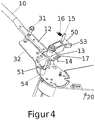
- eine auseinander gezogene Ansicht der Teile der Holmverstellung;
- Figur 5
- eine schematische Ansicht zur Erläuterung der Relativpositionen der Drehachsen der Holmstange, des Rasthebels und dessen Raststift im Rastzustand.
- In
Figur 1 ist ein Anwendungsbeispiel einer Ausführungsform des erfindungsgemäßen Holm-Verstellmechanismus zeigt, die dazu dienen soll, zu verdeutlichen, wo und an welcher Stelle diese Ausführungsform des Holm-Verstellmechanismus bei einem Rasenmäher oder ähnlichen Garten- und anderen Geräten 20 verwendbar ist. Obwohl inFigur 1 als Beispiel ein Hinterrad 101 gezeigt ist, kann das Gerät auch in anderer Weise unter der Führung mit Hilfe des Holm über den Boden bewegbar ausgebildet sein - In den
Figuren 1 und2 ist der insgesamt mit 30 bezeichnete Holm Verstellmechanismus durch eine Abdeckung 61, 62 verdeckt dargestellt, wobei die Abdeckung 61 eine Aussparung 63 aufweist, durch die hindurch sich ein Betätigungsvorsprung 53 eines Rasthebels 50 erstreckt, der mit Hilfe des Betätigungsvorsprungs 53 aus einer Raststellung heraus bewegbar ist, um den Holm 10 auf verschiedene Höhen einzustellen oder ein vollständiges Umlegen des Holms 10 über das Gerät 20 umzulegen, wie dies anhand derFiguren 2 bis 4 nachfolgend noch näher erläutert wird,. - Wie dies insbesondere aus den Figuren in den 3 und 4 erkennbar ist, umfasst der Holm-Verstellmechanismus 30 eine an dem Gerät 20 befestigte Holm-Aufnahmeplatte 32, an der das dem Gerät 20 zugewandte freie Ende 12 des Holms 10 beispielsweise durch eine Schraube 31 drehbar gelagert ist, die sich durch entsprechende Bohrungen in der Holm-Aufnahmeplatte 32 und des Endes 12 des Holms 10 erstreckt und eine erste Drehachse bildet.
- An diesem freien Ende 12 des Holms ist eine in
Figur 4 gezeigte Rastplatte 13 beispielsweise durch Schweißen befestigt, die sich im Wesentlichen parallel zur Aufnahmeplatte erstreckt. - Die Rastplatte 13 weist eine sich im Wesentlichen bogenförmig um die erste Drehachse 31 erstreckende Endkante 17 mit einer Anzahl von Rastkerben 14 auf, in die ein Passstift 15 eingreifen kann, der an dem Rasthebel 50 befestigt ist.
- Die Rastkerben 14 weisen vorzugsweise eine prismatische Fom auf, die sich ausgehend von der Endkante 17 in Richtung auf die erste Drehachse 13 verengt, Der Rasthebel 50 ist an seinem dem Passstift entgegengesetzten Ende um eine an der Holm-Aufnahmeplatte 32 befestigte Welle 51 drehbar und an seinem der Welle 51 entgegengesetzten Ende mit dem Betätigungsvorsprung 53 versehen, der in der Ausnehmung 63 eines ersten Teils 61 einer Abdeckung der Holm-Aufnahme verschiebbar ist, wie dies insbesondere aus den
Figuren 1 und2 zu erkennen ist. - Der Rasthebel 50 ist durch eine in
Figur 4 nur schematisch dargestellte Feder 16 in die Raststellung vorgespannt. - Die Anordnung des Drehpunktes 31 des Holms 10 und des Drehpunktes 51 des Rasthebels 50 ist in der insbesondere aus
Figur 5 erkennbaren Weise so gewählt, dass der Rasthebel 50 nur auf Druck oder Zug beansprucht wird. Dies wird dadurch erreicht, dass der Drehpunkt 51 des Rasthebels 50 auf einer Kreisbahn 21 der Drehung des Holms 10 auf der Holm-Aufnahmeplatte 13 und gegenüber der Längsachse des Holms in dessen Betriebsstellungen seitlich versetzt angeordnet ist, wobei der Raststift 15 im eingerasteten Zustand vorzugsweise ebenfalls auf der Kreisbahn 21 der Drehung der Rastplatte 13 um die erste Drehachse 31 liegt. Damit wird keine bzw. nur eine minimale Rotation des Rasthebels 50 bei einer Krafteinwirkung auf den Holm 10 verursacht. Durch dieses Aufbau gelingt es, dass System nahezu spielfrei zu gestalten. - Bei Verwendung eines U-förmigen Holms, bei dem die freien Enden der Holmstangen 10 über eine Querstange miteinander verbunden sind, ist diese Ausführungsform des Holm-Verstellmechanismen vorzugsweise auf beiden Seiten spiegelsymmetrisch zur Längsachse des Gerätes 20 angeordnet.
- Hierbei sind die die Wellen 51 der Rasthebel 50 vorzugsweise über eine sich in Querrichtung erstreckende Stange miteinander verbunden oder als Teil von dieser ausgebildet, und die Rasthebel 50 sind drehfest mit den jeweiligen Enden dieser Stange verbunden, so dass eine Drehung des Hebels 50 an einer Seite um ihren gemeinsamen Drehpunkt in der Mittelachse der Welle 51 auf die gegenüberliegende Seite des Gerätes 20 übertragen wird. Vorzugsweise ist hierbei jedem Rasthebel 50 eine eigene Vorspannfeder 16 oder eine andere elastische Einrichtung zugeordnet. Auf diese Weise kann eine geringfügige Verdrehung oder Torsion der die Rasthebel miteinander verbindende Stange oder ein konstruktiv bedingtes Spiel zwischen der Verbindungsstange und den Rasthebeln zugelassen und ausgenutzt werden.
- Bei dem Eingriff des Passstiftes 15 in eine der Kerben 14 der Rastplatte 13 wird der Holm 10 in seiner Drehbewegung gesperrt. Dreht man nun auf einer der beiden Seiten den Rasthebel 50 gegen die Wirkung der Feder 16, so wird der Holm wieder freigegeben und kann sich um seine Drehachse bewegen, die durch die Schraube 31 bestimmt ist.
- Die Rastplatte 13 weist bei der in
Figur 4 dargestellten Ausführungsform drei Rastkerben und damit drei Verrastungsmöglichkeiten auf, mit denen man drei Holmhöhen einstellen kann. Selbstverständlich kann auch eine andere Anzahl von Rastkerben verwendet werden. Weiterhin ist es möglich den Holm komplett umzulegen. - Die die Wellen 51 verbindende Koppelstange kann vorzugsweise durch ein Rohr 54, welches zur Befestigung einer Heckklappe oder dergleichen des Gerätes 20 dient, verlaufen. Somit kann man ohne einen zusätzlichen Kanal eine Kopplung der Rasthebel 50 erreichen.
Claims (6)
- Vorrichtung zur Einstellung der Position eines Holms zum Bewegen und/oder Steuern eines ortsbeweglichen Gerätes (20), bei der der Holm mindestens eine Holmstange (10), deren erstes Ende (12) drehbar an einem Ende des Gerätes (20) befestigt ist, deren zweites Ende einen Handgriff trägt, [] einen Verstellmechanismus (30) mit einer an dem Gerät (20) angeordneten Holm-Aufnahmeplatte (32) aufweist, an der das erste Ende der Holmstange (10) um die erste Drehachse (31) herum drehbar und auf mehrere Schwenk-stellungen einstellbar an dem Gerät (20)] befestigt ist, und Rasteinrichtungen (15, 50) zur Festlegung der Holmstange (10) in zumindest einer Schwenkstellung aufweist,
dadurch gekennzeichnet, dass die Rasteinrichtungen eine das erste Ende der Holmstange (10) auf der dem Handgriff entgegengesetzten Seite der Drehachse (31) verlängernde Rastplatte (13), die eine Anzahl von Rastkerben (14) aufweist, und einen Rasthebel (50) einschließen, dessen erstes Ende auf der zweiten Drehachse (26) auf der Holm-Aufnahmeplatte (7) drehbar befestigt ist, und dessen zweites Ende einen Raststift (15) trägt, der in die Rastkerben (14) einrastbar ist und in die Raststellung durch elastische Einrichtungen (16) vorgespannt ist, dass die erste Drehachse (6) und die zweite Drehachse (26) im Wesentlichen parallel zu einander angeordnet sind, dass die Rastplatte (13) eine sich im Wesentlichen bogenförmig um die erste Drehachse (6) erstreckende Endkante (17) aufweist, dass sich die Rastkerben (14) von der Endkante (17) der Rastplatte (13) aus in Richtung auf die erste Drehachse (6) erstrecken, und dass die Rastkerben (14) eine prismatische Form aufweisen und sich in Richtung auf die erste Drehachse (6) derart verengen, dass der Raststift (15) im eingerasteten Zustand auf der Kreisbahn (21) der Drehung der Rastplatte (13) um die erste Drehachse (6) liegt. - Vorrichtung nach Anspruch 1, dadurch gekennzeichnet, dass der Drehpunkt des Rasthebels (50) gegenüber der Längsachse des Holms (10) in dessen Betriebsstellungen seitlich versetzt angeordnet ist.
- Vorrichtung nach einem oder mehreren der vorhergehenden Ansprüche, dadurch gekennzeichnet, dass zwei Holmstangen (11) an entgegengesetzten Seiten des Gerätes (20) vorgesehen sind, deren zweites Ende durch eine den Handgriff tragende Verbindungsstange verbunden sind, dass ein jeweiliger Verstellmechanismus (30) an jedem ersten Ende (12) der Holmstangen (11) angeordnet ist, und dass die Drehachsen (51) der Rasthebel (50) über eine Verbindungsstange miteinander und mit den Rasthebeln (50) drehfest verbunden sind.
- Vorrichtung nach Anspruch 3, dadurch gekennzeichnet, dass sich die Verbindungsstange durch ein an dem Gerät vorgesehenes rohrförmiges Element oder durch den freien Raum von einer Seite der Geräts zu dessen andere Seite erstreckt.
- Vorrichtung nach Anspruch 3 oder 4, dadurch gekennzeichnet, dass die Rasthebel (50) jedes der Verstellmechanismen über jeweilige elastische Einrichtungen (16) in die Raststellung vorgespannt sind.
- Vorrichtung nach einem oder mehreren der vorhergehenden Ansprüche, dadurch gekennzeichnet, dass die Elemente des Verstellmechanismus (31) durch eine Abdeckung (61, 62) abgedeckt sind, und dass sich ein Vorsprung (53) des Rasthebels durch eine Aussparung (63) in der Abdeckung (61) aus dieser heraus erstreckt.
Applications Claiming Priority (1)
| Application Number | Priority Date | Filing Date | Title |
|---|---|---|---|
| DE102017006160.2A DE102017006160A1 (de) | 2017-06-27 | 2017-06-27 | Vorrichtung zur Einstellung der Position eines Holms eines ortsbeweglichen Gerätes |
Publications (2)
| Publication Number | Publication Date |
|---|---|
| EP3420793A1 true EP3420793A1 (de) | 2019-01-02 |
| EP3420793B1 EP3420793B1 (de) | 2021-04-28 |
Family
ID=62778722
Family Applications (1)
| Application Number | Title | Priority Date | Filing Date |
|---|---|---|---|
| EP18179430.6A Active EP3420793B1 (de) | 2017-06-27 | 2018-06-24 | Vorrichtung zur einstellung der position eines holms eines ortsbeweglichen geräts |
Country Status (2)
| Country | Link |
|---|---|
| EP (1) | EP3420793B1 (de) |
| DE (1) | DE102017006160A1 (de) |
Cited By (1)
| Publication number | Priority date | Publication date | Assignee | Title |
|---|---|---|---|---|
| US12550818B2 (en) | 2021-10-15 | 2026-02-17 | Techtronic Cordless Gp | Mower |
Citations (4)
| Publication number | Priority date | Publication date | Assignee | Title |
|---|---|---|---|---|
| US2756064A (en) * | 1951-01-20 | 1956-07-24 | Carl M Rutledge | Collapsible frame for golf carts |
| DE202013005119U1 (de) * | 2013-06-06 | 2013-06-18 | Viking Gmbh | Arbeitsgerät |
| EP2777377A1 (de) * | 2013-03-15 | 2014-09-17 | Husqvarna AB | Türheber und Griff für handgeführten Mäher |
| EP3141101A1 (de) * | 2015-09-11 | 2017-03-15 | GGP Italy S.p.A. | Vorrichtung zur verstellung der höhe eines rasenmähergriffs und zur neigung davon |
Family Cites Families (2)
| Publication number | Priority date | Publication date | Assignee | Title |
|---|---|---|---|---|
| AU441006B2 (en) * | 1970-08-20 | 1973-09-28 | Victa Limited | An adjustable handle for lawnmowers (divisional of no 16715/70) |
| US9439352B2 (en) * | 2015-02-02 | 2016-09-13 | Husqvarna Ab | Handle height adjuster for walk behind mower |
-
2017
- 2017-06-27 DE DE102017006160.2A patent/DE102017006160A1/de not_active Ceased
-
2018
- 2018-06-24 EP EP18179430.6A patent/EP3420793B1/de active Active
Patent Citations (4)
| Publication number | Priority date | Publication date | Assignee | Title |
|---|---|---|---|---|
| US2756064A (en) * | 1951-01-20 | 1956-07-24 | Carl M Rutledge | Collapsible frame for golf carts |
| EP2777377A1 (de) * | 2013-03-15 | 2014-09-17 | Husqvarna AB | Türheber und Griff für handgeführten Mäher |
| DE202013005119U1 (de) * | 2013-06-06 | 2013-06-18 | Viking Gmbh | Arbeitsgerät |
| EP3141101A1 (de) * | 2015-09-11 | 2017-03-15 | GGP Italy S.p.A. | Vorrichtung zur verstellung der höhe eines rasenmähergriffs und zur neigung davon |
Cited By (1)
| Publication number | Priority date | Publication date | Assignee | Title |
|---|---|---|---|---|
| US12550818B2 (en) | 2021-10-15 | 2026-02-17 | Techtronic Cordless Gp | Mower |
Also Published As
| Publication number | Publication date |
|---|---|
| EP3420793B1 (de) | 2021-04-28 |
| DE102017006160A1 (de) | 2018-12-27 |
Similar Documents
| Publication | Publication Date | Title |
|---|---|---|
| EP1671527B1 (de) | Verbindungselement | |
| DE69916014T2 (de) | Verfahren und vorrichtung zum zusammenbau eines sitzes für einen selbstfahrenden rasenmäher | |
| DE102007003091B3 (de) | Verstellbare Lenksäule für ein Kraftfahrzeug | |
| DE10334089A1 (de) | Gelenkmechanismus für einen Fahrzeugsitz und Fahrzeugsitz, der mit einem solchen Mechanismus ausgestattet ist | |
| DE10343355A1 (de) | Verriegelungseinheit für ein bewegliches Schließelement | |
| EP2656708A1 (de) | Zinkenstriegel | |
| EP3272207B1 (de) | Arbeitsgerät mit über ein schwenkgelenk verbundenen teilgehäusen | |
| DE10343354A1 (de) | Verriegelungseinheit für ein bewegliches Schließelement | |
| EP2842860B1 (de) | Halte- und Freigabemechanik zum Halten und Freigeben einer Seilaufnahmevorrichtung | |
| DE10217534A1 (de) | Verriegelungseinrichtung von Einstelleinrichtungen für Lenksäulen von Kraftfahrzeugen | |
| DE19936951C2 (de) | Verstellpropeller für Sportboote und Sportjachten | |
| EP3420793B1 (de) | Vorrichtung zur einstellung der position eines holms eines ortsbeweglichen geräts | |
| DE2824071A1 (de) | Spann- und schneidezange fuer ein band bzw. einen riemen | |
| DE4436096C2 (de) | Klinkenschaltwerk zum Antrieb einer Verstellvorrichtungen für einen Fahrzeugsitz | |
| DE29505891U1 (de) | Hacke mit verstellbarer Hackenkopfneigung | |
| DE102004045338A1 (de) | Höheneinstellung an einem fahrbaren Arbeitsgerät | |
| EP2560557B1 (de) | Zugvorrichtung einer chirurgischen retraktionsvorrichtung | |
| EP3476205A1 (de) | Handschere, insbesondere ast-, hecken- und/oder gartenschere | |
| DE202005018037U1 (de) | Rasenmäher mit Höhenverstellung | |
| DE2915245C2 (de) | Mähbalken | |
| DE8033674U1 (de) | Vorrichtung zum blockieren eines verschiebbaren organs in bezug auf eine stange einer bueromaschine | |
| DE102004018591B4 (de) | Bodenbearbeitungsgerät mit Winkelverstellung | |
| DE102016112052A1 (de) | Ährenheber | |
| DE2835733A1 (de) | Anzeigevorrichtung fuer die ausloesehaerte einer schraubenfeder bei einer sicherheitsskibindung | |
| EP1169900B1 (de) | Handgeführtes Landschaftspflegegerät |
Legal Events
| Date | Code | Title | Description |
|---|---|---|---|
| PUAI | Public reference made under article 153(3) epc to a published international application that has entered the european phase |
Free format text: ORIGINAL CODE: 0009012 |
|
| STAA | Information on the status of an ep patent application or granted ep patent |
Free format text: STATUS: THE APPLICATION HAS BEEN PUBLISHED |
|
| AK | Designated contracting states |
Kind code of ref document: A1 Designated state(s): AL AT BE BG CH CY CZ DE DK EE ES FI FR GB GR HR HU IE IS IT LI LT LU LV MC MK MT NL NO PL PT RO RS SE SI SK SM TR |
|
| AX | Request for extension of the european patent |
Extension state: BA ME |
|
| 19U | Interruption of proceedings before grant |
Effective date: 20190418 |
|
| 19W | Proceedings resumed before grant after interruption of proceedings |
Effective date: 20191202 |
|
| STAA | Information on the status of an ep patent application or granted ep patent |
Free format text: STATUS: REQUEST FOR EXAMINATION WAS MADE |
|
| 17P | Request for examination filed |
Effective date: 20200214 |
|
| GRAP | Despatch of communication of intention to grant a patent |
Free format text: ORIGINAL CODE: EPIDOSNIGR1 |
|
| STAA | Information on the status of an ep patent application or granted ep patent |
Free format text: STATUS: GRANT OF PATENT IS INTENDED |
|
| INTG | Intention to grant announced |
Effective date: 20201113 |
|
| GRAS | Grant fee paid |
Free format text: ORIGINAL CODE: EPIDOSNIGR3 |
|
| GRAA | (expected) grant |
Free format text: ORIGINAL CODE: 0009210 |
|
| STAA | Information on the status of an ep patent application or granted ep patent |
Free format text: STATUS: THE PATENT HAS BEEN GRANTED |
|
| AK | Designated contracting states |
Kind code of ref document: B1 Designated state(s): AL AT BE BG CH CY CZ DE DK EE ES FI FR GB GR HR HU IE IS IT LI LT LU LV MC MK MT NL NO PL PT RO RS SE SI SK SM TR |
|
| REG | Reference to a national code |
Ref country code: GB Ref legal event code: FG4D Free format text: NOT ENGLISH |
|
| REG | Reference to a national code |
Ref country code: CH Ref legal event code: EP |
|
| REG | Reference to a national code |
Ref country code: AT Ref legal event code: REF Ref document number: 1386041 Country of ref document: AT Kind code of ref document: T Effective date: 20210515 |
|
| REG | Reference to a national code |
Ref country code: DE Ref legal event code: R096 Ref document number: 502018004976 Country of ref document: DE |
|
| REG | Reference to a national code |
Ref country code: IE Ref legal event code: FG4D Free format text: LANGUAGE OF EP DOCUMENT: GERMAN |
|
| REG | Reference to a national code |
Ref country code: LT Ref legal event code: MG9D |
|
| PG25 | Lapsed in a contracting state [announced via postgrant information from national office to epo] |
Ref country code: FI Free format text: LAPSE BECAUSE OF FAILURE TO SUBMIT A TRANSLATION OF THE DESCRIPTION OR TO PAY THE FEE WITHIN THE PRESCRIBED TIME-LIMIT Effective date: 20210428 Ref country code: LT Free format text: LAPSE BECAUSE OF FAILURE TO SUBMIT A TRANSLATION OF THE DESCRIPTION OR TO PAY THE FEE WITHIN THE PRESCRIBED TIME-LIMIT Effective date: 20210428 Ref country code: HR Free format text: LAPSE BECAUSE OF FAILURE TO SUBMIT A TRANSLATION OF THE DESCRIPTION OR TO PAY THE FEE WITHIN THE PRESCRIBED TIME-LIMIT Effective date: 20210428 Ref country code: NL Free format text: LAPSE BECAUSE OF FAILURE TO SUBMIT A TRANSLATION OF THE DESCRIPTION OR TO PAY THE FEE WITHIN THE PRESCRIBED TIME-LIMIT Effective date: 20210428 Ref country code: BG Free format text: LAPSE BECAUSE OF FAILURE TO SUBMIT A TRANSLATION OF THE DESCRIPTION OR TO PAY THE FEE WITHIN THE PRESCRIBED TIME-LIMIT Effective date: 20210728 |
|
| PG25 | Lapsed in a contracting state [announced via postgrant information from national office to epo] |
Ref country code: IS Free format text: LAPSE BECAUSE OF FAILURE TO SUBMIT A TRANSLATION OF THE DESCRIPTION OR TO PAY THE FEE WITHIN THE PRESCRIBED TIME-LIMIT Effective date: 20210828 Ref country code: GR Free format text: LAPSE BECAUSE OF FAILURE TO SUBMIT A TRANSLATION OF THE DESCRIPTION OR TO PAY THE FEE WITHIN THE PRESCRIBED TIME-LIMIT Effective date: 20210729 Ref country code: PT Free format text: LAPSE BECAUSE OF FAILURE TO SUBMIT A TRANSLATION OF THE DESCRIPTION OR TO PAY THE FEE WITHIN THE PRESCRIBED TIME-LIMIT Effective date: 20210830 Ref country code: LV Free format text: LAPSE BECAUSE OF FAILURE TO SUBMIT A TRANSLATION OF THE DESCRIPTION OR TO PAY THE FEE WITHIN THE PRESCRIBED TIME-LIMIT Effective date: 20210428 Ref country code: NO Free format text: LAPSE BECAUSE OF FAILURE TO SUBMIT A TRANSLATION OF THE DESCRIPTION OR TO PAY THE FEE WITHIN THE PRESCRIBED TIME-LIMIT Effective date: 20210728 Ref country code: PL Free format text: LAPSE BECAUSE OF FAILURE TO SUBMIT A TRANSLATION OF THE DESCRIPTION OR TO PAY THE FEE WITHIN THE PRESCRIBED TIME-LIMIT Effective date: 20210428 Ref country code: SE Free format text: LAPSE BECAUSE OF FAILURE TO SUBMIT A TRANSLATION OF THE DESCRIPTION OR TO PAY THE FEE WITHIN THE PRESCRIBED TIME-LIMIT Effective date: 20210428 Ref country code: RS Free format text: LAPSE BECAUSE OF FAILURE TO SUBMIT A TRANSLATION OF THE DESCRIPTION OR TO PAY THE FEE WITHIN THE PRESCRIBED TIME-LIMIT Effective date: 20210428 |
|
| REG | Reference to a national code |
Ref country code: NL Ref legal event code: MP Effective date: 20210428 |
|
| REG | Reference to a national code |
Ref country code: DE Ref legal event code: R119 Ref document number: 502018004976 Country of ref document: DE |
|
| PG25 | Lapsed in a contracting state [announced via postgrant information from national office to epo] |
Ref country code: SK Free format text: LAPSE BECAUSE OF FAILURE TO SUBMIT A TRANSLATION OF THE DESCRIPTION OR TO PAY THE FEE WITHIN THE PRESCRIBED TIME-LIMIT Effective date: 20210428 Ref country code: SM Free format text: LAPSE BECAUSE OF FAILURE TO SUBMIT A TRANSLATION OF THE DESCRIPTION OR TO PAY THE FEE WITHIN THE PRESCRIBED TIME-LIMIT Effective date: 20210428 Ref country code: ES Free format text: LAPSE BECAUSE OF FAILURE TO SUBMIT A TRANSLATION OF THE DESCRIPTION OR TO PAY THE FEE WITHIN THE PRESCRIBED TIME-LIMIT Effective date: 20210428 Ref country code: EE Free format text: LAPSE BECAUSE OF FAILURE TO SUBMIT A TRANSLATION OF THE DESCRIPTION OR TO PAY THE FEE WITHIN THE PRESCRIBED TIME-LIMIT Effective date: 20210428 Ref country code: RO Free format text: LAPSE BECAUSE OF FAILURE TO SUBMIT A TRANSLATION OF THE DESCRIPTION OR TO PAY THE FEE WITHIN THE PRESCRIBED TIME-LIMIT Effective date: 20210428 Ref country code: CZ Free format text: LAPSE BECAUSE OF FAILURE TO SUBMIT A TRANSLATION OF THE DESCRIPTION OR TO PAY THE FEE WITHIN THE PRESCRIBED TIME-LIMIT Effective date: 20210428 Ref country code: DK Free format text: LAPSE BECAUSE OF FAILURE TO SUBMIT A TRANSLATION OF THE DESCRIPTION OR TO PAY THE FEE WITHIN THE PRESCRIBED TIME-LIMIT Effective date: 20210428 Ref country code: MC Free format text: LAPSE BECAUSE OF FAILURE TO SUBMIT A TRANSLATION OF THE DESCRIPTION OR TO PAY THE FEE WITHIN THE PRESCRIBED TIME-LIMIT Effective date: 20210428 |
|
| REG | Reference to a national code |
Ref country code: CH Ref legal event code: PL |
|
| PLBE | No opposition filed within time limit |
Free format text: ORIGINAL CODE: 0009261 |
|
| STAA | Information on the status of an ep patent application or granted ep patent |
Free format text: STATUS: NO OPPOSITION FILED WITHIN TIME LIMIT |
|
| PG25 | Lapsed in a contracting state [announced via postgrant information from national office to epo] |
Ref country code: LU Free format text: LAPSE BECAUSE OF NON-PAYMENT OF DUE FEES Effective date: 20210624 |
|
| 26N | No opposition filed |
Effective date: 20220131 |
|
| PG25 | Lapsed in a contracting state [announced via postgrant information from national office to epo] |
Ref country code: LI Free format text: LAPSE BECAUSE OF NON-PAYMENT OF DUE FEES Effective date: 20210630 Ref country code: IE Free format text: LAPSE BECAUSE OF NON-PAYMENT OF DUE FEES Effective date: 20210624 Ref country code: DE Free format text: LAPSE BECAUSE OF NON-PAYMENT OF DUE FEES Effective date: 20220101 Ref country code: CH Free format text: LAPSE BECAUSE OF NON-PAYMENT OF DUE FEES Effective date: 20210630 |
|
| PG25 | Lapsed in a contracting state [announced via postgrant information from national office to epo] |
Ref country code: IS Free format text: LAPSE BECAUSE OF FAILURE TO SUBMIT A TRANSLATION OF THE DESCRIPTION OR TO PAY THE FEE WITHIN THE PRESCRIBED TIME-LIMIT Effective date: 20210828 Ref country code: FR Free format text: LAPSE BECAUSE OF NON-PAYMENT OF DUE FEES Effective date: 20210628 Ref country code: AL Free format text: LAPSE BECAUSE OF FAILURE TO SUBMIT A TRANSLATION OF THE DESCRIPTION OR TO PAY THE FEE WITHIN THE PRESCRIBED TIME-LIMIT Effective date: 20210428 |
|
| PG25 | Lapsed in a contracting state [announced via postgrant information from national office to epo] |
Ref country code: IT Free format text: LAPSE BECAUSE OF FAILURE TO SUBMIT A TRANSLATION OF THE DESCRIPTION OR TO PAY THE FEE WITHIN THE PRESCRIBED TIME-LIMIT Effective date: 20210428 |
|
| PGFP | Annual fee paid to national office [announced via postgrant information from national office to epo] |
Ref country code: BE Payment date: 20220627 Year of fee payment: 5 |
|
| PG25 | Lapsed in a contracting state [announced via postgrant information from national office to epo] |
Ref country code: CY Free format text: LAPSE BECAUSE OF FAILURE TO SUBMIT A TRANSLATION OF THE DESCRIPTION OR TO PAY THE FEE WITHIN THE PRESCRIBED TIME-LIMIT Effective date: 20210428 |
|
| PG25 | Lapsed in a contracting state [announced via postgrant information from national office to epo] |
Ref country code: HU Free format text: LAPSE BECAUSE OF FAILURE TO SUBMIT A TRANSLATION OF THE DESCRIPTION OR TO PAY THE FEE WITHIN THE PRESCRIBED TIME-LIMIT; INVALID AB INITIO Effective date: 20180624 |
|
| P01 | Opt-out of the competence of the unified patent court (upc) registered |
Effective date: 20230912 |
|
| REG | Reference to a national code |
Ref country code: BE Ref legal event code: MM Effective date: 20230630 |
|
| PG25 | Lapsed in a contracting state [announced via postgrant information from national office to epo] |
Ref country code: MK Free format text: LAPSE BECAUSE OF FAILURE TO SUBMIT A TRANSLATION OF THE DESCRIPTION OR TO PAY THE FEE WITHIN THE PRESCRIBED TIME-LIMIT Effective date: 20210428 |
|
| PG25 | Lapsed in a contracting state [announced via postgrant information from national office to epo] |
Ref country code: BE Free format text: LAPSE BECAUSE OF NON-PAYMENT OF DUE FEES Effective date: 20230630 |
|
| PG25 | Lapsed in a contracting state [announced via postgrant information from national office to epo] |
Ref country code: TR Free format text: LAPSE BECAUSE OF FAILURE TO SUBMIT A TRANSLATION OF THE DESCRIPTION OR TO PAY THE FEE WITHIN THE PRESCRIBED TIME-LIMIT Effective date: 20210428 |
|
| REG | Reference to a national code |
Ref country code: AT Ref legal event code: MM01 Ref document number: 1386041 Country of ref document: AT Kind code of ref document: T Effective date: 20230624 |
|
| PG25 | Lapsed in a contracting state [announced via postgrant information from national office to epo] |
Ref country code: MT Free format text: LAPSE BECAUSE OF FAILURE TO SUBMIT A TRANSLATION OF THE DESCRIPTION OR TO PAY THE FEE WITHIN THE PRESCRIBED TIME-LIMIT Effective date: 20210428 |
|
| PG25 | Lapsed in a contracting state [announced via postgrant information from national office to epo] |
Ref country code: AT Free format text: LAPSE BECAUSE OF NON-PAYMENT OF DUE FEES Effective date: 20230624 |
|
| PG25 | Lapsed in a contracting state [announced via postgrant information from national office to epo] |
Ref country code: AT Free format text: LAPSE BECAUSE OF NON-PAYMENT OF DUE FEES Effective date: 20230624 |
|
| PGFP | Annual fee paid to national office [announced via postgrant information from national office to epo] |
Ref country code: AT Payment date: 20260410 Year of fee payment: 5 |
|
| PGFP | Annual fee paid to national office [announced via postgrant information from national office to epo] |
Ref country code: GB Payment date: 20260623 Year of fee payment: 9 |