EP3418476A1 - Schliesszylinder mit einem zum schliessen berechtigten schlüssel - Google Patents
Schliesszylinder mit einem zum schliessen berechtigten schlüssel Download PDFInfo
- Publication number
- EP3418476A1 EP3418476A1 EP18176591.8A EP18176591A EP3418476A1 EP 3418476 A1 EP3418476 A1 EP 3418476A1 EP 18176591 A EP18176591 A EP 18176591A EP 3418476 A1 EP3418476 A1 EP 3418476A1
- Authority
- EP
- European Patent Office
- Prior art keywords
- key
- core
- lock cylinder
- magnet
- Prior art date
- Legal status (The legal status is an assumption and is not a legal conclusion. Google has not performed a legal analysis and makes no representation as to the accuracy of the status listed.)
- Granted
Links
Images

Classifications
-
- E—FIXED CONSTRUCTIONS
- E05—LOCKS; KEYS; WINDOW OR DOOR FITTINGS; SAFES
- E05B—LOCKS; ACCESSORIES THEREFOR; HANDCUFFS
- E05B47/00—Operating or controlling locks or other fastening devices by electric or magnetic means
- E05B47/0038—Operating or controlling locks or other fastening devices by electric or magnetic means using permanent magnets
- E05B47/0045—Operating or controlling locks or other fastening devices by electric or magnetic means using permanent magnets keys with permanent magnets
-
- E—FIXED CONSTRUCTIONS
- E05—LOCKS; KEYS; WINDOW OR DOOR FITTINGS; SAFES
- E05B—LOCKS; ACCESSORIES THEREFOR; HANDCUFFS
- E05B11/00—Devices preventing keys from being removed from the lock ; Devices preventing falling or pushing out of keys
- E05B11/06—Devices preventing keys from being removed from the lock ; Devices preventing falling or pushing out of keys for catching skeleton or incorrect keys
-
- E—FIXED CONSTRUCTIONS
- E05—LOCKS; KEYS; WINDOW OR DOOR FITTINGS; SAFES
- E05B—LOCKS; ACCESSORIES THEREFOR; HANDCUFFS
- E05B27/00—Cylinder locks or other locks with tumbler pins or balls that are set by pushing the key in
- E05B27/0057—Cylinder locks or other locks with tumbler pins or balls that are set by pushing the key in with increased picking resistance
- E05B27/006—Cylinder locks or other locks with tumbler pins or balls that are set by pushing the key in with increased picking resistance whereby a small rotation without the correct key blocks further rotation of the rotor
- E05B27/0064—Cylinder locks or other locks with tumbler pins or balls that are set by pushing the key in with increased picking resistance whereby a small rotation without the correct key blocks further rotation of the rotor whereby the rotor is irreversibly blocked or can only be moved back with an authorized tool or key
-
- E—FIXED CONSTRUCTIONS
- E05—LOCKS; KEYS; WINDOW OR DOOR FITTINGS; SAFES
- E05B—LOCKS; ACCESSORIES THEREFOR; HANDCUFFS
- E05B47/00—Operating or controlling locks or other fastening devices by electric or magnetic means
- E05B47/0038—Operating or controlling locks or other fastening devices by electric or magnetic means using permanent magnets
Definitions
- the invention relates to a lock cylinder with a key authorized to close, with a rotatably mounted in a housing core, with a locking mechanism for selectively blocking or releasing the movement of the core, with a closing channel for inserting a shank of the key into the core, with means of inserted into the lock channel key to control the locking mechanism, with a key magnet arranged in the key and with a guided in a pocket of the core magnetic locking body.
- the locking mechanism of the lock cylinder for example, be an electronic locking mechanism which is controlled by a code of an electronic component in the key.
- the locking mechanism may also have generally conventional mechanical pin tumblers, which are controlled by closing recesses in the key. Key magnets complicate copies of the authorized key to close, for example by means of a 3D printer, a manual reworking of the outer mold or by means of an unauthorized reading and copying of the code.
- a locking device has become known in which the core has a reaching into the closing channel guide for a magnetic ball.
- the key has a recess for receiving and supporting the ball. This ball faces a recess in a locking ring and is attracted by a magnet in the key.
- a disadvantage of the known locking device is that in an attempted unlocking the lock cylinder with a key not authorized to close the key without key magnets, the key can be removed again. Thus, manipulation attempts remain undetected and the manipulation attempt can be repeated.
- the invention is based on the problem, so far as to form a lock cylinder with a key authorized to close, so that a manipulation attempt is easily detected.
- the housing in the direction of rotation of the core in addition to the key withdrawal position has a catch pocket for partially receiving the locking body and that the force of the key magnet for holding the locking body is dimensioned within the core.
- the movement of the core is initially blocked by the locking mechanism in a manipulation attempt with a key copy not authorized to close.
- the core can initially be initially a bit far out of the key withdrawal position out before the locking body enters the catch pocket and there prevents further movement of the core.
- a key that is not authorized to close without a key magnet can neither close the lock cylinder nor be removed from the lock cylinder.
- the lock cylinder has a key withdrawal lock and an unauthorized unlocking attempt can be easily determined. Since a key authorized to close both activates the locking mechanism and keeps the locking body completely inside the core, the core can be rotated and thus the locking cylinder can be closed.
- the catching of a key not authorized to close designed according to another advantageous embodiment of the invention structurally particularly simple when the catching bag is offset by a rotation angle of the core of about 30 ° relative to the key withdrawal position. With a rotation of the core by 30 ° conventional locking mechanisms of known lock cylinders hold the key in the closing channel. The key can then not be pulled out of the closing channel.
- the locking body is reliably held according to an advantageous embodiment of the invention in the key withdrawal position in its intended position when the locking body is held in the key withdrawal position completely within the pocket of the core. Another advantage of this design is that the locking body thereby does not have to be attracted by the key magnet. The locking body is thereby held in a position in the core, in which he can be easily held by the key magnet.
- Blocking the movement of the core can be ensured particularly reliable according to another advantageous embodiment of the invention, if the bag has the shape of a segment in the core.
- the lock cylinder is structurally particularly simple according to another advantageous embodiment of the invention, when the catch pocket is formed as a trough-shaped depression of the wall of the housing.
- a complete turning back of the core in the key withdrawal position located in the trap pocket locking body is reliably prevented according to another advantageous embodiment of the invention, when the catching pocket is arranged in key withdrawal position at least partially outside the area covered by the pocket in the core area.
- the locking body is designed as a ball, preferably steel ball.
- the locking body could be moved by an almost arbitrary force in the catch bag.
- the locking body could be biased by gravity or a spring force in the direction of catch bag.
- a particularly reliable movement of the locking body in the catch pocket can be achieved easily according to another advantageous embodiment of the invention, if the housing has a housing magnet for attracting the locking body into the catch pocket and that the force exerted by the housing magnet on the locking body is smaller than that of force applied to the key magnet.
- the housing magnet allows any installation position of the lock cylinder.
- a spring force for biasing the locking body of the housing magnet requires no consuming to be created space in the core.
- the lock cylinder can be used in various ways according to another advantageous embodiment of the invention, when the housing for each direction of rotation of the core has a catch pocket and a respective housing magnet.
- the lock cylinder can be used in right and left hinged doors.
- the key magnet could, for example, be cast in the key. However, this leads to a very complex production of the key. To simplify the installation of the key magnet, it contributes according to another advantageous embodiment of the invention, when the key magnet is arranged in a stop axially abutting the core.
- a removal or destruction of the housing magnet can be reliably avoided according to another advantageous embodiment of the invention, when the housing magnet is arranged outside a front side of the lock cylinder.
- the housing magnet is arranged inaccessible in the assembled state of the lock cylinder.
- a hole can be arranged in the stop of the key or a side wall of the lock cylinder and fasten the key magnet or the housing magnet in the bore, for example by pressing or gluing.
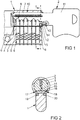
- the locking cylinder 1 has a core 4 rotatable in a housing 3 and a locking mechanism 5 for selectively blocking or releasing the movement of the core 4.
- the locking mechanism 5 has in the illustrated embodiment a number of in the lock cylinder 1 arranged pin tumblers 6, which are driven by arranged in a shaft 7 of the key 2 closing recesses 8. In one embodiment, not shown, the locking mechanism 5 may also have an electronically controllable actuator for blocking or releasing the movement of the core 4.
- the core 4 is connected to a cam 9 and has a closing channel 10 for receiving the shank 7 of the key 2.
- the key 2 also has a Reide 11 and a stop 12, with which it is supported on one end face of the core 4.
- the stop 12 is shown here in partial section and has a bore 13 for receiving a key magnet 14.
- a magnetic locking body 15 is arranged in a pocket 16.
- the blocking body 15 is designed as a steel ball and held completely in the illustrated position within the core 4.
- the locking body 15 is attracted by the key magnet 14 and held on the upper wall of the pocket 16.
- FIG. 2 shows the lock cylinder 1 with the introduced authorized to close the key 2 from FIG. 1 in a key withdrawal position, in which the key 2 can be easily inserted into the lock cylinder 1 and withdrawn therefrom.
- the key magnet 14 not arranged in the cutting plane is in FIG. 2 shown in dashed lines.
- catch pockets 17, 18 are arranged in the housing.
- the housing 3 Each have a housing magnet 19, 20.
- the housing magnets 19, 20 exert a lower attraction force on the locking body 15 as the key magnet 14th
- FIG. 3 shows enlarged a portion of the lock cylinder 1 from FIG. 2 without a key. It can be seen here that the blocking body 15 is not attracted to the upper wall of the pocket 16. A rotation of the core 2 is determined by the in FIG. 1 described locking mechanism 5 prevents. Furthermore, in FIG. 3 it can be seen that the catching pocket 17, 18 is arranged at least partially outside the area covered by the pocket 16 in the core 4 in the illustrated key withdrawal position. Thus, the core 4 only the assume key withdrawal position when the locking body 15, as shown, not in one of the catch pockets 17, 18 is located.
- FIG. 4 shows the closing of the lock cylinder 1 with the authorized to close the key 2.
- the in FIG. 1 described blocking mechanism 5 is driven and the locking body 15 is here attracted by the key magnet 14 in a arranged at the upper end of the pocket 16 trough 21.
- the core 4 can be rotated relative to the housing 3.
- FIG. 5 shows an attempted closing of the lock cylinder 1 with a not authorized to close key 22, in which the in FIG. 4 described key magnet 14 is missing.
- the core 4 can be initially rotated.
- the locking body 15 can initially move freely in the pocket 16, this is attracted by one of the housing magnet 19 in one of the catch pockets 17.
- a complete turning back of the core 4 is prevented in the key withdrawal position, because the locking body 15 remains in the catching pocket 17.
- the key 22 which is not authorized to close is caught in the lock cylinder 1.
Landscapes
- Lock And Its Accessories (AREA)
Abstract
Description
- Die Erfindung betrifft einen Schließzylinder mit einem zum Schließen berechtigten Schlüssel, mit einem drehbar in einem Gehäuse gelagerten Kern, mit einem Sperrmechanismus zur wahlweisen Blockierung oder Freigabe der Bewegung des Kerns, mit einem Schließkanal zum Einführen eines Schaftes des Schlüssels in den Kern, mit Mitteln des in den Schließkanal eingeführten Schlüssels zu Ansteuerung des Sperrmechanismus, mit einem in dem Schlüssel angeordneten Schlüsselmagneten und mit einem in einer Tasche des Kerns geführten magnetischen Sperrkörper.
- Der Sperrmechanismus des Schließzylinders kann beispielsweise ein elektronischer Sperrmechanismus sein, welcher von einem Code eines elektronischen Bauteils im Schlüssel ansteuerbar ist. Ebenso kann der Sperrmechanismus auch allgemein gebräuchliche mechanische Stiftzuhaltungen aufweisen, welche von Schließausnehmungen im Schlüssel ansteuerbar sind. Schlüsselmagneten erschweren Kopien des zum Schließen berechtigten Schlüssels beispielsweise mittels eines 3D Druckers, eines manuellen Nacharbeiten der äußeren Form oder mittels eines unberechtigten Auslesen und Kopieren des Codes.
- Aus der
DE 30 16 393 A1 ist eine Schließvorrichtung bekannt geworden, bei der der Kern eine bis in den Schließkanal reichende Führung für eine magnetische Kugel hat. Der Schlüssel weist eine Ausnehmung zur Aufnahme und Abstützung der Kugel auf. Diese Kugel steht einer Ausnehmung in einem Rastring gegenüber und wird von einem Magneten im Schlüssel angezogen. Nachteilig bei der bekannten Schließvorrichtung ist, dass bei einem versuchten Entriegeln des Schließzylinders mit einem nicht zum Schließen berechtigten Schlüssel ohne Schlüsselmagneten der Schlüssel wieder abgezogen werden kann. Damit bleiben Manipulationsversuche unerkannt und der Manipulationsversuch kann wiederholt werden. - Der Erfindung liegt das Problem zugrunde, einen Schließzylinder mit einem zum Schließen berechtigten Schlüssel so weiter zu bilden, dass ein Manipulationsversuch einfach erkannt wird.
- Dieses Problem wird erfindungsgemäß dadurch gelöst, dass das Gehäuse in Drehrichtung des Kerns neben der Schlüsselabzugsstellung eine Fangtasche zur teilweisen Aufnahme des Sperrkörpers hat und dass die Kraft des Schlüsselmagneten zur Halterung des Sperrkörpers innerhalb des Kerns bemessen ist.
- Durch diese Gestaltung wird bei einem Manipulationsversuch mit einer nicht zum Schließen berechtigten Schlüsselkopie die Bewegung des Kerns zunächst von dem Sperrmechanismus blockiert. Bei einer Überwindung des Sperrmechanismus lässt sich der Kern zunächst anfänglich ein Stück weit aus der Schlüsselabzugsstellung heraus drehen, bevor der Sperrkörper in die Fangtasche gelangt und dort eine weitere Bewegung des Kerns verhindert. In der Folge kann ein nicht zum Schließen berechtigter Schlüssel ohne Schlüsselmagnet weder den Schließzylinder schließen, noch aus dem Schließzylinder entnommen werden. Damit weist der Schließzylinder eine Schlüsselabzugssperre auf und ein unberechtigter Entriegelungsversuch lässt sich einfach feststellen. Da ein zum Schließen berechtigter Schlüssel sowohl den Sperrmechanismus ansteuert, als auch den Sperrkörper vollständig innerhalb des Kerns hält, lässt sich der Kern drehen und damit der Schließzylinder schließen.
- Das Fangen eines nicht zum Schließen berechtigten Schlüssels gestaltet sich gemäß einer anderen vorteilhaften Weiterbildung der Erfindung konstruktiv besonders einfach, wenn die Fangtasche um einen Drehwinkel des Kerns von etwa 30° gegenüber der Schlüsselabzugsstellung versetzt ist. Bei einer Drehung des Kerns um 30° halten übliche Sperrmechanismen von bekannten Schließzylindern den Schlüssel im Schließkanal. Der Schlüssel kann dann nicht aus dem Schließkanal herausgezogen werden.
- Der Sperrkörper ist gemäß einer vorteilhaften Weiterbildung der Erfindung in der Schlüsselabzugsstellung zuverlässig in seiner vorgesehenen Lage gehalten, wenn der Sperrkörper in der Schlüsselabzugsstellung vollständig innerhalb der Tasche des Kerns gehalten ist. Ein weiterer Vorteil dieser Gestaltung ist, dass der Sperrkörper hierdurch nicht von dem Schlüsselmagneten angezogen werden muss. Der Sperrkörper ist hierdurch in einer Lage im Kern gehalten, in der er von dem Schlüsselmagneten einfach festgehalten werden kann.
- Eine Blockierung der Bewegung des Kerns lässt sich gemäß einer anderen vorteilhaften Weiterbildung der Erfindung besonders zuverlässig sicherstellen, wenn die Tasche im Kern die Form eines Segments hat.
- Beim Schließen des Schließzylinders mit dem zum Schließen berechtigten Schlüssel wird der Sperrkörper gemäß einer anderen vorteilhaften Weiterbildung der Erfindung zuverlässig von den Fangtaschen fern gehalten, wenn die Tasche im Kern unmittelbar unterhalb des Schließkanals eine Mulde zur Aufnahme des Sperrkörpers hat. Hierdurch werden Fehlfunktionen zuverlässig vermieden.
- Der Schließzylinder gestaltet sich gemäß einer anderen vorteilhaften Weiterbildung der Erfindung konstruktiv besonders einfach, wenn die Fangtasche als muldenförmige Vertiefung der Wandung des Gehäuses ausgebildet ist.
- Ein vollständiges Zurückdrehen des Kerns in die Schlüsselabzugsstellung bei in der Fangtasche befindlichem Sperrkörper wird gemäß einer anderen vorteilhaften Weiterbildung der Erfindung zuverlässig verhindert, wenn die Fangtasche in Schlüsselabzugsstellung zumindest teilweise außerhalb des von der Tasche im Kern überdeckten Bereichs angeordnet ist.
- Zur weiteren konstruktiven Vereinfachung des Schließzylinders trägt es gemäß einer anderen vorteilhaften Weiterbildung der Erfindung bei, wenn der Sperrkörper als Kugel, vorzugsweise Stahlkugel, ausgebildet ist.
- Der Sperrkörper könnte von einer nahezu beliebigen Kraft in die Fangtasche bewegt werden. Beispielsweise könnte der Sperrkörper durch die Schwerkraft oder eine Federkraft in Richtung Fangtasche vorbelastet sein. Eine besonders zuverlässige Bewegung des Sperrkörpers in die Fangtasche lässt sich gemäß einer anderen vorteilhaften Weiterbildung der Erfindung einfach erreichen, wenn das Gehäuse einen Gehäusemagneten zur Anziehung des Sperrkörpers in die Fangtasche aufweist und dass die von dem Gehäusemagneten auf den Sperrkörper ausgeübte Kraft kleiner ist als die von dem Schlüsselmagneten ausgeübte Kraft. Im Vergleich zur Schwerkraft ermöglicht der Gehäusemagnet eine beliebige Einbaulage des Schließzylinders. Im Vergleich zu einer Federkraft zur Vorspannung des Sperrkörpers benötigt der Gehäusemagnet keinen aufwändig zu erzeugenden Bauraum in dem Kern.
- Der Schließzylinder lässt sich gemäß einer anderen vorteilhaften Weiterbildung der Erfindung vielfältig einsetzbar, wenn das Gehäuse für jede Drehrichtung des Kerns jeweils eine Fangtasche und jeweils einen Gehäusemagneten hat. Durch diese Gestaltung kann der Schließzylinder in rechts- und linksanschlagenden Türen eingesetzt werden.
- Der Schlüsselmagnet könnte beispielsweise in dem Schlüssel vergossen sein. Dies führt jedoch zu einer sehr aufwändigen Fertigung des Schlüssels. Zur Vereinfachung der Montage des Schlüsselmagneten trägt es gemäß einer anderen vorteilhaften Weiterbildung der Erfindung bei, wenn der Schlüsselmagnet in einem axial an den Kern anstoßenden Anschlag angeordnet ist.
- Eine Entfernung oder Zerstörung des Gehäusemagneten lässt sich gemäß einer anderen vorteilhaften Weiterbildung der Erfindung zuverlässig vermeiden, wenn der Gehäusemagnet außerhalb einer Stirnseite des Schließzylinders angeordnet ist. Durch diese Gestaltung ist der Gehäusemagnet im montierten Zustand des Schließzylinders unzugänglich angeordnet.
- Zur weiteren Vereinfachung der Montage trägt es gemäß einer anderen vorteilhaften Weiterbildung der Erfindung bei, wenn zumindest einer der Bauteile des Schlüsselmagneten oder des Gehäusemagneten in einer einseitig offenen Bohrung befestigt ist. Durch diese Gestaltung lässt sich eine Bohrung in den Anschlag des Schlüssels oder einer Seitenwand des Schließzylinders anordnen und der Schlüsselmagnet oder der Gehäusemagnet in der Bohrung beispielsweise durch Verpressung oder Verklebung befestigen.
- Die Erfindung lässt zahlreiche Ausführungsformen zu. Zur weiteren Verdeutlichung ihres Grundprinzips ist eine davon in der Zeichnung dargestellt und wird nachfolgend beschrieben. Diese zeigt in
- Fig. 1
- einen Schließzylinder mit einem Schlüssel,
- Fig. 2
- eine Schnittdarstellung durch den Schließzylinder aus
Figur 1 entlang der Linie II - II, - Fig. 3
- vergrößert einen Teilbereich des Schließzylinders aus
Figur 1 in einem Grundzustand, - Fig. 4
- den Schließzylinder aus
Figur 3 beim Schließen mit einem zum Schließen berechtigten Schlüssel, - Fig. 5
- den Schließzylinder aus
Figur 3 beim Schließen mit einem nicht zum Schließen berechtigten Schlüssel. -
Figur 1 zeigt einen Schließzylinder 1 mit einem zum Schließen berechtigten Schlüssel 2. Der Schließzylinder 1 hat einen in einem Gehäuse 3 drehbaren Kern 4 und einen Sperrmechanismus 5 zum wahlweisen Blockieren oder Freigabe der Bewegung des Kerns 4. Der Sperrmechanismus 5 weist in dem dargestellten Ausführungsbeispiel eine Reihe von im Schließzylinder 1 angeordneten Stiftzuhaltungen 6 auf, welche von in einem Schaft 7 des Schlüssels 2 angeordneten Schließausnehmungen 8 angesteuert werden. In einem nicht dargestellten Ausführungsbeispiel kann der Sperrmechanismus 5 auch einen elektronisch ansteuerbaren Aktor zur Blockierung oder Freigabe der Bewegung des Kerns 4 aufweisen. Der Kern 4 ist mit einem Schließbart 9 verbunden und hat einen Schließkanal 10 zur Aufnahme des Schaftes 7 des Schlüssels 2. Der Schlüssel 2 hat zudem eine Reide 11 und einen Anschlag 12, mit dem er sich an einer Stirnseite des Kerns 4 abstützt. - Der Anschlag 12 ist hier im Teilschnitt dargestellt und hat eine Bohrung 13 zur Aufnahme eines Schlüsselmagneten 14. In dem Kern 4 ist ein magnetischer Sperrkörper 15 in einer Tasche 16 angeordnet. Der Sperrkörper 15 ist als Stahlkugel ausgebildet und in der dargestellten Stellung vollständig innerhalb des Kerns 4 gehalten. Der Sperrkörper 15 wird von dem Schlüsselmagneten 14 angezogen und an der oberen Wandung der Tasche 16 gehalten.
-
Figur 2 zeigt den Schließzylinder 1 mit dem eingeführten zum Schließen berechtigten Schlüssel 2 ausFigur 1 in einer Schlüsselabzugsstellung, in der der Schlüssel 2 einfach in den Schließzylinder 1 eingeführt und aus diesem abgezogen werden kann. Der nicht in der Schnittebene angeordnete Schlüsselmagnet 14 ist inFigur 2 gestrichelt dargestellt.
In einem Drehwinkel des Kerns um etwa 30° zur Schlüsselabzugsstellung sind in dem Gehäuse 3 Fangtaschen 17, 18 angeordnet. Unmittelbar unterhalb der Fangtaschen 17, 18 hat das Gehäuse 3 jeweils einen Gehäusemagneten 19, 20. Die Gehäusemagneten 19, 20 üben eine geringere Anziehungskraft auf den Sperrkörper 15 auf als der Schlüsselmagnet 14. -
Figur 3 zeigt vergrößert einen Teilbereich des Schließzylinders 1 ausFigur 2 ohne Schlüssel. Hierbei ist zu erkennen, dass der Sperrkörper 15 nicht an die obere Wandung der Tasche 16 angezogen ist. Eine Drehung des Kerns 2 wird durch den inFigur 1 beschriebenen Sperrmechanismus 5 verhindert. Weiterhin ist inFigur 3 ersichtlich, dass die Fangtasche 17, 18 in der dargestellten Schlüsselabzugsstellung zumindest teilweise außerhalb des von der Tasche 16 im Kern 4 überdeckten Bereichs angeordnet ist. Damit kann der Kern 4 nur die dargestellte Schlüsselabzugsstellung einnehmen, wenn sich der Sperrkörper 15, wie dargestellt, nicht in einer der Fangtaschen 17, 18 befindet. -
Figur 4 zeigt das Schließen des Schließzylinders 1 mit dem zum Schließen berechtigten Schlüssel 2. Der inFigur 1 beschriebene Sperrmechanismus 5 ist angesteuert und der Sperrkörper 15 ist hier von dem Schlüsselmagneten 14 in eine am oberen Ende der Tasche 16 angeordnete Mulde 21 angezogen. Der Kern 4 kann gegenüber dem Gehäuse 3 verdreht werden. -
Figur 5 zeigt ein versuchtes Schließen des Schließzylinders 1 mit einem nicht zum Schließen berechtigten Schlüssel 22, bei dem der inFigur 4 beschriebene Schlüsselmagnet 14 fehlt. Nach dem Überwinden des inFigur 1 beschriebenen Sperrmechanismus 5 kann der Kern 4 anfänglich gedreht werden. Da sich jedoch der Sperrkörper 15 zunächst frei in der Tasche 16 bewegen kann, wird dieser von einem der Gehäusemagneten 19 in eine der Fangtaschen 17 angezogen. Damit wird eine Weiterdrehung des Kerns 4 verhindert. Jedoch wird auch ein vollständiges Zurückdrehen des Kerns 4 in die Schlüsselabzugsstellung verhindert, weil der Sperrkörper 15 in der Fangtasche 17 verbleibt. Damit ist der nicht zum Schließen berechtigte Schlüssel 22 in dem Schließzylinder 1 gefangen.
Claims (13)
- Schließzylinder (1) mit einem zum Schließen berechtigten Schlüssel (2), mit einem drehbar in einem Gehäuse (3) gelagerten Kern (4), mit einem Sperrmechanismus (5) zur wahlweisen Blockierung oder Freigabe der Bewegung des Kerns (4), mit einem Schließkanal (10) zum Einführen eines Schaftes (7) des Schlüssels (2) in den Kern (4), mit Mitteln des in den Schließkanal (10) eingeführten Schlüssels (2) zu Ansteuerung des Sperrmechanismus (5), mit einem in dem Schlüssel (2) angeordneten Schlüsselmagneten (14) und einem in einer Tasche (16) des Kerns (4) geführten magnetischen Sperrkörper (15), dadurch gekennzeichnet, dass das Gehäuse (3) in Drehrichtung des Kerns (4) neben der Schlüsselabzugsstellung eine Fangtasche (17, 18) zur teilweisen Aufnahme des Sperrkörpers (15) hat und dass die Kraft des Schlüsselmagneten (14) zur Halterung des Sperrkörpers (15) innerhalb des Kerns (4) bemessen ist.
- Schließzylinder nach Anspruch 1, dadurch gekennzeichnet, dass die Fangtasche (17, 18) um einen Drehwinkel des Kerns von etwa 30° gegenüber der Schlüsselabzugsstellung versetzt ist.
- Schließzylinder nach Anspruch 1 oder 2, dadurch gekennzeichnet, dass der Sperrkörper (15) in der Schlüsselabzugsstellung vollständig innerhalb der Tasche (16) des Kerns (4) gehalten ist.
- Schließzylinder nach einem der vorhergehenden Ansprüche, dadurch gekennzeichnet, dass die Tasche (16) im Kern (4) die Form eines Segments hat.
- Schließzylinder nach einem der vorhergehenden Ansprüche, dadurch gekennzeichnet, dass die Tasche (16) im Kern (4) unmittelbar unterhalb des Schließkanals (10) eine Mulde (21) zur Aufnahme des Sperrkörpers (15) hat.
- Schließzylinder nach einem der vorhergehenden Ansprüche, dadurch gekennzeichnet, dass die Fangtasche (17, 18) als muldenförmige Vertiefung einer Wandung des Gehäuses (3) ausgebildet ist.
- Schließzylinder nach einem der vorhergehenden Ansprüche, dadurch gekennzeichnet, dass die Fangtasche (17, 18) in Schlüsselabzugsstellung zumindest teilweise außerhalb des von der Tasche (16) im Kern (4) überdeckten Bereichs angeordnet ist.
- Schließzylinder nach einem der vorhergehenden Ansprüche, dadurch gekennzeichnet, dass der Sperrkörper (15) als Kugel, vorzugsweise Stahlkugel, ausgebildet ist.
- Schließzylinder nach einem der vorhergehenden Ansprüche, dadurch gekennzeichnet, dass das Gehäuse (3) einen Gehäusemagneten (19, 20) zur Anziehung des Sperrkörpers (16) in die Fangtasche (17, 18) aufweist und dass die von dem Gehäusemagneten (19, 20) auf den Sperrkörper (16) ausgeübte Kraft kleiner ist als die von dem Schlüsselmagneten (14) ausgeübte Kraft.
- Schließzylinder nach einem der vorhergehenden Ansprüche, dadurch gekennzeichnet, dass das Gehäuse (3) für jede Drehrichtung des Kerns (4) jeweils eine Fangtasche (17, 18) und jeweils einen Gehäusemagneten (19, 20) hat.
- Schließzylinder nach einem der vorhergehenden Ansprüche, dadurch gekennzeichnet, dass der Schlüsselmagnet (14) in einem axial an den Kern (4) anstoßenden Anschlag (12) angeordnet ist.
- Schließzylinder nach einem der vorhergehenden Ansprüche, dadurch gekennzeichnet, dass der Gehäusemagnet (19, 20) außerhalb einer Stirnseite des Schließzylinders (1) angeordnet ist.
- Schließzylinder nach einem der vorhergehenden Ansprüche, dadurch gekennzeichnet, dass zumindest einer der Bauteile des Schlüsselmagneten (14) oder des Gehäusemagneten (19, 20) in einer einseitig offenen Bohrung (13) befestigt ist.
Priority Applications (1)
| Application Number | Priority Date | Filing Date | Title |
|---|---|---|---|
| PL18176591T PL3418476T3 (pl) | 2017-06-22 | 2018-06-07 | Cylinder zamykający z kluczem uprawnionym do zamykania |
Applications Claiming Priority (1)
| Application Number | Priority Date | Filing Date | Title |
|---|---|---|---|
| DE102017210553.4A DE102017210553A1 (de) | 2017-06-22 | 2017-06-22 | Schließzylinder mit einem zum Schließen berechtigten Schlüssel |
Publications (2)
| Publication Number | Publication Date |
|---|---|
| EP3418476A1 true EP3418476A1 (de) | 2018-12-26 |
| EP3418476B1 EP3418476B1 (de) | 2020-11-18 |
Family
ID=62567483
Family Applications (1)
| Application Number | Title | Priority Date | Filing Date |
|---|---|---|---|
| EP18176591.8A Active EP3418476B1 (de) | 2017-06-22 | 2018-06-07 | Schliesszylinder mit einem zum schliessen berechtigten schlüssel |
Country Status (4)
| Country | Link |
|---|---|
| EP (1) | EP3418476B1 (de) |
| DE (1) | DE102017210553A1 (de) |
| ES (1) | ES2837576T3 (de) |
| PL (1) | PL3418476T3 (de) |
Cited By (3)
| Publication number | Priority date | Publication date | Assignee | Title |
|---|---|---|---|---|
| US11536047B1 (en) | 2022-08-22 | 2022-12-27 | Winloc Ag | Key plug, a cylinder lock, a cylinder lock and key combination and a method to manufacture a key plug |
| US11542724B1 (en) | 2022-08-22 | 2023-01-03 | Winloc Ag | Key blank, a key, and a cylinder lock and key combination |
| US11613909B1 (en) | 2022-08-22 | 2023-03-28 | Winloc Ag | Key blank, a coded key and a cylinder lock and key system with improved stop arrangement |
Citations (6)
| Publication number | Priority date | Publication date | Assignee | Title |
|---|---|---|---|---|
| US3416336A (en) * | 1965-12-22 | 1968-12-17 | Liquidonics Inc | Magnetic lock devices |
| DE3016393A1 (de) | 1980-02-08 | 1981-08-13 | Evva-Werk Spezialerzeugung von Zylinder- und Sicherheitsschlössern GmbH & Co KG, 1120 Wien | Schliessvorrichtung |
| US4627251A (en) * | 1984-09-17 | 1986-12-09 | Bhate Suresh K | Combined mechanical and magnetic locking system |
| DE10318913A1 (de) * | 2003-04-26 | 2004-11-11 | Aug. Winkhaus Gmbh & Co. Kg | Schließzylinder |
| DE102004056606A1 (de) * | 2004-11-24 | 2006-06-01 | Aug. Winkhaus Gmbh & Co. Kg | Schließzylinder |
| EP3101206A1 (de) * | 2015-06-03 | 2016-12-07 | Assa Abloy Aube Anjou | Magnetisches sicherheitsschloss |
-
2017
- 2017-06-22 DE DE102017210553.4A patent/DE102017210553A1/de not_active Withdrawn
-
2018
- 2018-06-07 EP EP18176591.8A patent/EP3418476B1/de active Active
- 2018-06-07 PL PL18176591T patent/PL3418476T3/pl unknown
- 2018-06-07 ES ES18176591T patent/ES2837576T3/es active Active
Patent Citations (6)
| Publication number | Priority date | Publication date | Assignee | Title |
|---|---|---|---|---|
| US3416336A (en) * | 1965-12-22 | 1968-12-17 | Liquidonics Inc | Magnetic lock devices |
| DE3016393A1 (de) | 1980-02-08 | 1981-08-13 | Evva-Werk Spezialerzeugung von Zylinder- und Sicherheitsschlössern GmbH & Co KG, 1120 Wien | Schliessvorrichtung |
| US4627251A (en) * | 1984-09-17 | 1986-12-09 | Bhate Suresh K | Combined mechanical and magnetic locking system |
| DE10318913A1 (de) * | 2003-04-26 | 2004-11-11 | Aug. Winkhaus Gmbh & Co. Kg | Schließzylinder |
| DE102004056606A1 (de) * | 2004-11-24 | 2006-06-01 | Aug. Winkhaus Gmbh & Co. Kg | Schließzylinder |
| EP3101206A1 (de) * | 2015-06-03 | 2016-12-07 | Assa Abloy Aube Anjou | Magnetisches sicherheitsschloss |
Cited By (3)
| Publication number | Priority date | Publication date | Assignee | Title |
|---|---|---|---|---|
| US11536047B1 (en) | 2022-08-22 | 2022-12-27 | Winloc Ag | Key plug, a cylinder lock, a cylinder lock and key combination and a method to manufacture a key plug |
| US11542724B1 (en) | 2022-08-22 | 2023-01-03 | Winloc Ag | Key blank, a key, and a cylinder lock and key combination |
| US11613909B1 (en) | 2022-08-22 | 2023-03-28 | Winloc Ag | Key blank, a coded key and a cylinder lock and key system with improved stop arrangement |
Also Published As
| Publication number | Publication date |
|---|---|
| ES2837576T3 (es) | 2021-06-30 |
| EP3418476B1 (de) | 2020-11-18 |
| PL3418476T3 (pl) | 2021-04-19 |
| DE102017210553A1 (de) | 2018-12-27 |
Similar Documents
| Publication | Publication Date | Title |
|---|---|---|
| DE19908085C1 (de) | Vorrichtung zur Aufnahme und Halterung eines Identifikationsgebers, wie eines elektronischen Schlüssels, insbesondere für einen Zündanlaßschalter und/oder eine Lenksäuleneverriegelung eines Motorfahrzeugs | |
| DE202011106208U1 (de) | Schließzylinder für ein Schloss | |
| EP3418476B1 (de) | Schliesszylinder mit einem zum schliessen berechtigten schlüssel | |
| DE112007001826T5 (de) | Schlossmechanismus | |
| DE102004039531A1 (de) | Sperrmechanismus | |
| DE102009043305B4 (de) | Schließvorrichtung | |
| EP3258036B1 (de) | Beschlag mit einer beschlagsicherung | |
| DE102011014797B3 (de) | Schließzylinder mit zugehörigem Schlüssel | |
| DE202016102422U1 (de) | Schloss | |
| EP2441906B1 (de) | Schließzylinder | |
| DE20021352U1 (de) | Schließzylinder | |
| EP2476824B1 (de) | Schließvorrichtung | |
| DE2743769A1 (de) | Schloss und codierter schluessel zur betaetigung des schlosses | |
| WO2013030077A1 (de) | Drehschliesszylinder und sicherheitsschlüssel | |
| DE102006024063B4 (de) | Schloss mit einem durch einen elektrischmechanisch betätigten Sperrstift verriegelbaren Schließzylinder | |
| DE10329414B4 (de) | Schließvorrichtung | |
| EP2848754B1 (de) | Schliesszylinder | |
| EP1705321B1 (de) | Schließzylinder | |
| DE102019213852A1 (de) | Schließzylinder | |
| DE19753434A1 (de) | Zylinderschloß mit bedienbarer Verriegelung | |
| AT4485U1 (de) | Schliesszylinder | |
| WO2007036348A1 (de) | Verriegelungseinrichtung | |
| DE1703370C3 (de) | Absperrbarer Schubriegelverschluß, insbesondere für Kabelverteilerschränke od.dgl | |
| DE102019100757A1 (de) | Verriegelungsvorrichtung sowie Verriegelungssystem | |
| DE10237985B4 (de) | Schloss |
Legal Events
| Date | Code | Title | Description |
|---|---|---|---|
| PUAI | Public reference made under article 153(3) epc to a published international application that has entered the european phase |
Free format text: ORIGINAL CODE: 0009012 |
|
| STAA | Information on the status of an ep patent application or granted ep patent |
Free format text: STATUS: THE APPLICATION HAS BEEN PUBLISHED |
|
| AK | Designated contracting states |
Kind code of ref document: A1 Designated state(s): AL AT BE BG CH CY CZ DE DK EE ES FI FR GB GR HR HU IE IS IT LI LT LU LV MC MK MT NL NO PL PT RO RS SE SI SK SM TR |
|
| AX | Request for extension of the european patent |
Extension state: BA ME |
|
| STAA | Information on the status of an ep patent application or granted ep patent |
Free format text: STATUS: REQUEST FOR EXAMINATION WAS MADE |
|
| 17P | Request for examination filed |
Effective date: 20190426 |
|
| RAX | Requested extension states of the european patent have changed |
Extension state: ME Payment date: 20190426 Extension state: BA Payment date: 20190426 |
|
| RBV | Designated contracting states (corrected) |
Designated state(s): AL AT BE BG CH CY CZ DE DK EE ES FI FR GB GR HR HU IE IS IT LI LT LU LV MC MK MT NL NO PL PT RO RS SE SI SK SM TR |
|
| RIC1 | Information provided on ipc code assigned before grant |
Ipc: E05B 47/00 20060101AFI20200520BHEP Ipc: E05B 27/00 20060101ALI20200520BHEP Ipc: E05B 11/06 20060101ALI20200520BHEP |
|
| GRAP | Despatch of communication of intention to grant a patent |
Free format text: ORIGINAL CODE: EPIDOSNIGR1 |
|
| STAA | Information on the status of an ep patent application or granted ep patent |
Free format text: STATUS: GRANT OF PATENT IS INTENDED |
|
| INTG | Intention to grant announced |
Effective date: 20200703 |
|
| GRAS | Grant fee paid |
Free format text: ORIGINAL CODE: EPIDOSNIGR3 |
|
| GRAA | (expected) grant |
Free format text: ORIGINAL CODE: 0009210 |
|
| STAA | Information on the status of an ep patent application or granted ep patent |
Free format text: STATUS: THE PATENT HAS BEEN GRANTED |
|
| AK | Designated contracting states |
Kind code of ref document: B1 Designated state(s): AL AT BE BG CH CY CZ DE DK EE ES FI FR GB GR HR HU IE IS IT LI LT LU LV MC MK MT NL NO PL PT RO RS SE SI SK SM TR |
|
| AX | Request for extension of the european patent |
Extension state: BA ME |
|
| REG | Reference to a national code |
Ref country code: GB Ref legal event code: FG4D Free format text: NOT ENGLISH |
|
| REG | Reference to a national code |
Ref country code: CH Ref legal event code: EP |
|
| REG | Reference to a national code |
Ref country code: IE Ref legal event code: FG4D Free format text: LANGUAGE OF EP DOCUMENT: GERMAN |
|
| REG | Reference to a national code |
Ref country code: DE Ref legal event code: R096 Ref document number: 502018003023 Country of ref document: DE |
|
| REG | Reference to a national code |
Ref country code: AT Ref legal event code: REF Ref document number: 1335959 Country of ref document: AT Kind code of ref document: T Effective date: 20201215 |
|
| REG | Reference to a national code |
Ref country code: NL Ref legal event code: FP |
|
| PG25 | Lapsed in a contracting state [announced via postgrant information from national office to epo] |
Ref country code: FI Free format text: LAPSE BECAUSE OF FAILURE TO SUBMIT A TRANSLATION OF THE DESCRIPTION OR TO PAY THE FEE WITHIN THE PRESCRIBED TIME-LIMIT Effective date: 20201118 Ref country code: RS Free format text: LAPSE BECAUSE OF FAILURE TO SUBMIT A TRANSLATION OF THE DESCRIPTION OR TO PAY THE FEE WITHIN THE PRESCRIBED TIME-LIMIT Effective date: 20201118 Ref country code: PT Free format text: LAPSE BECAUSE OF FAILURE TO SUBMIT A TRANSLATION OF THE DESCRIPTION OR TO PAY THE FEE WITHIN THE PRESCRIBED TIME-LIMIT Effective date: 20210318 Ref country code: NO Free format text: LAPSE BECAUSE OF FAILURE TO SUBMIT A TRANSLATION OF THE DESCRIPTION OR TO PAY THE FEE WITHIN THE PRESCRIBED TIME-LIMIT Effective date: 20210218 Ref country code: GR Free format text: LAPSE BECAUSE OF FAILURE TO SUBMIT A TRANSLATION OF THE DESCRIPTION OR TO PAY THE FEE WITHIN THE PRESCRIBED TIME-LIMIT Effective date: 20210219 |
|
| PG25 | Lapsed in a contracting state [announced via postgrant information from national office to epo] |
Ref country code: BG Free format text: LAPSE BECAUSE OF FAILURE TO SUBMIT A TRANSLATION OF THE DESCRIPTION OR TO PAY THE FEE WITHIN THE PRESCRIBED TIME-LIMIT Effective date: 20210218 Ref country code: IS Free format text: LAPSE BECAUSE OF FAILURE TO SUBMIT A TRANSLATION OF THE DESCRIPTION OR TO PAY THE FEE WITHIN THE PRESCRIBED TIME-LIMIT Effective date: 20210318 Ref country code: LV Free format text: LAPSE BECAUSE OF FAILURE TO SUBMIT A TRANSLATION OF THE DESCRIPTION OR TO PAY THE FEE WITHIN THE PRESCRIBED TIME-LIMIT Effective date: 20201118 Ref country code: SE Free format text: LAPSE BECAUSE OF FAILURE TO SUBMIT A TRANSLATION OF THE DESCRIPTION OR TO PAY THE FEE WITHIN THE PRESCRIBED TIME-LIMIT Effective date: 20201118 |
|
| REG | Reference to a national code |
Ref country code: LT Ref legal event code: MG9D |
|
| PG25 | Lapsed in a contracting state [announced via postgrant information from national office to epo] |
Ref country code: HR Free format text: LAPSE BECAUSE OF FAILURE TO SUBMIT A TRANSLATION OF THE DESCRIPTION OR TO PAY THE FEE WITHIN THE PRESCRIBED TIME-LIMIT Effective date: 20201118 |
|
| REG | Reference to a national code |
Ref country code: ES Ref legal event code: FG2A Ref document number: 2837576 Country of ref document: ES Kind code of ref document: T3 Effective date: 20210630 |
|
| PG25 | Lapsed in a contracting state [announced via postgrant information from national office to epo] |
Ref country code: LT Free format text: LAPSE BECAUSE OF FAILURE TO SUBMIT A TRANSLATION OF THE DESCRIPTION OR TO PAY THE FEE WITHIN THE PRESCRIBED TIME-LIMIT Effective date: 20201118 Ref country code: SK Free format text: LAPSE BECAUSE OF FAILURE TO SUBMIT A TRANSLATION OF THE DESCRIPTION OR TO PAY THE FEE WITHIN THE PRESCRIBED TIME-LIMIT Effective date: 20201118 Ref country code: RO Free format text: LAPSE BECAUSE OF FAILURE TO SUBMIT A TRANSLATION OF THE DESCRIPTION OR TO PAY THE FEE WITHIN THE PRESCRIBED TIME-LIMIT Effective date: 20201118 Ref country code: CZ Free format text: LAPSE BECAUSE OF FAILURE TO SUBMIT A TRANSLATION OF THE DESCRIPTION OR TO PAY THE FEE WITHIN THE PRESCRIBED TIME-LIMIT Effective date: 20201118 Ref country code: EE Free format text: LAPSE BECAUSE OF FAILURE TO SUBMIT A TRANSLATION OF THE DESCRIPTION OR TO PAY THE FEE WITHIN THE PRESCRIBED TIME-LIMIT Effective date: 20201118 Ref country code: SM Free format text: LAPSE BECAUSE OF FAILURE TO SUBMIT A TRANSLATION OF THE DESCRIPTION OR TO PAY THE FEE WITHIN THE PRESCRIBED TIME-LIMIT Effective date: 20201118 |
|
| REG | Reference to a national code |
Ref country code: DE Ref legal event code: R097 Ref document number: 502018003023 Country of ref document: DE |
|
| PG25 | Lapsed in a contracting state [announced via postgrant information from national office to epo] |
Ref country code: DK Free format text: LAPSE BECAUSE OF FAILURE TO SUBMIT A TRANSLATION OF THE DESCRIPTION OR TO PAY THE FEE WITHIN THE PRESCRIBED TIME-LIMIT Effective date: 20201118 |
|
| PLBE | No opposition filed within time limit |
Free format text: ORIGINAL CODE: 0009261 |
|
| STAA | Information on the status of an ep patent application or granted ep patent |
Free format text: STATUS: NO OPPOSITION FILED WITHIN TIME LIMIT |
|
| 26N | No opposition filed |
Effective date: 20210819 |
|
| PG25 | Lapsed in a contracting state [announced via postgrant information from national office to epo] |
Ref country code: AL Free format text: LAPSE BECAUSE OF FAILURE TO SUBMIT A TRANSLATION OF THE DESCRIPTION OR TO PAY THE FEE WITHIN THE PRESCRIBED TIME-LIMIT Effective date: 20201118 |
|
| PG25 | Lapsed in a contracting state [announced via postgrant information from national office to epo] |
Ref country code: SI Free format text: LAPSE BECAUSE OF FAILURE TO SUBMIT A TRANSLATION OF THE DESCRIPTION OR TO PAY THE FEE WITHIN THE PRESCRIBED TIME-LIMIT Effective date: 20201118 |
|
| PG25 | Lapsed in a contracting state [announced via postgrant information from national office to epo] |
Ref country code: MC Free format text: LAPSE BECAUSE OF FAILURE TO SUBMIT A TRANSLATION OF THE DESCRIPTION OR TO PAY THE FEE WITHIN THE PRESCRIBED TIME-LIMIT Effective date: 20201118 |
|
| REG | Reference to a national code |
Ref country code: CH Ref legal event code: PL |
|
| REG | Reference to a national code |
Ref country code: BE Ref legal event code: MM Effective date: 20210630 |
|
| PG25 | Lapsed in a contracting state [announced via postgrant information from national office to epo] |
Ref country code: LU Free format text: LAPSE BECAUSE OF NON-PAYMENT OF DUE FEES Effective date: 20210607 |
|
| PG25 | Lapsed in a contracting state [announced via postgrant information from national office to epo] |
Ref country code: LI Free format text: LAPSE BECAUSE OF NON-PAYMENT OF DUE FEES Effective date: 20210630 Ref country code: IE Free format text: LAPSE BECAUSE OF NON-PAYMENT OF DUE FEES Effective date: 20210607 Ref country code: CH Free format text: LAPSE BECAUSE OF NON-PAYMENT OF DUE FEES Effective date: 20210630 |
|
| PG25 | Lapsed in a contracting state [announced via postgrant information from national office to epo] |
Ref country code: IS Free format text: LAPSE BECAUSE OF FAILURE TO SUBMIT A TRANSLATION OF THE DESCRIPTION OR TO PAY THE FEE WITHIN THE PRESCRIBED TIME-LIMIT Effective date: 20210318 |
|
| PG25 | Lapsed in a contracting state [announced via postgrant information from national office to epo] |
Ref country code: BE Free format text: LAPSE BECAUSE OF NON-PAYMENT OF DUE FEES Effective date: 20210630 |
|
| P01 | Opt-out of the competence of the unified patent court (upc) registered |
Effective date: 20230515 |
|
| PG25 | Lapsed in a contracting state [announced via postgrant information from national office to epo] |
Ref country code: CY Free format text: LAPSE BECAUSE OF FAILURE TO SUBMIT A TRANSLATION OF THE DESCRIPTION OR TO PAY THE FEE WITHIN THE PRESCRIBED TIME-LIMIT Effective date: 20201118 |
|
| PG25 | Lapsed in a contracting state [announced via postgrant information from national office to epo] |
Ref country code: HU Free format text: LAPSE BECAUSE OF FAILURE TO SUBMIT A TRANSLATION OF THE DESCRIPTION OR TO PAY THE FEE WITHIN THE PRESCRIBED TIME-LIMIT; INVALID AB INITIO Effective date: 20180607 |
|
| PG25 | Lapsed in a contracting state [announced via postgrant information from national office to epo] |
Ref country code: MK Free format text: LAPSE BECAUSE OF FAILURE TO SUBMIT A TRANSLATION OF THE DESCRIPTION OR TO PAY THE FEE WITHIN THE PRESCRIBED TIME-LIMIT Effective date: 20201118 |
|
| PG25 | Lapsed in a contracting state [announced via postgrant information from national office to epo] |
Ref country code: TR Free format text: LAPSE BECAUSE OF FAILURE TO SUBMIT A TRANSLATION OF THE DESCRIPTION OR TO PAY THE FEE WITHIN THE PRESCRIBED TIME-LIMIT Effective date: 20201118 |
|
| PG25 | Lapsed in a contracting state [announced via postgrant information from national office to epo] |
Ref country code: MT Free format text: LAPSE BECAUSE OF FAILURE TO SUBMIT A TRANSLATION OF THE DESCRIPTION OR TO PAY THE FEE WITHIN THE PRESCRIBED TIME-LIMIT Effective date: 20201118 |
|
| REG | Reference to a national code |
Ref country code: DE Ref legal event code: R081 Ref document number: 502018003023 Country of ref document: DE Owner name: AUG. WINKHAUS SE & CO. KG, DE Free format text: FORMER OWNER: AUG. WINKHAUS GMBH & CO. KG, 48291 TELGTE, DE Ref country code: DE Ref legal event code: R081 Ref document number: 502018003023 Country of ref document: DE Owner name: AUG. WINKHAUS SE, DE Free format text: FORMER OWNER: AUG. WINKHAUS GMBH & CO. KG, 48291 TELGTE, DE |
|
| PGFP | Annual fee paid to national office [announced via postgrant information from national office to epo] |
Ref country code: GB Payment date: 20250620 Year of fee payment: 8 |
|
| REG | Reference to a national code |
Ref country code: DE Ref legal event code: R081 Ref document number: 502018003023 Country of ref document: DE Owner name: AUG. WINKHAUS SE, DE Free format text: FORMER OWNER: AUG. WINKHAUS SE & CO. KG, 48291 TELGTE, DE |
|
| PGFP | Annual fee paid to national office [announced via postgrant information from national office to epo] |
Ref country code: ES Payment date: 20250718 Year of fee payment: 8 |
|
| PGFP | Annual fee paid to national office [announced via postgrant information from national office to epo] |
Ref country code: IT Payment date: 20250630 Year of fee payment: 8 |
|
| PGFP | Annual fee paid to national office [announced via postgrant information from national office to epo] |
Ref country code: PL Payment date: 20260601 Year of fee payment: 9 |
|
| PGFP | Annual fee paid to national office [announced via postgrant information from national office to epo] |
Ref country code: DE Payment date: 20260623 Year of fee payment: 9 |
|
| PGFP | Annual fee paid to national office [announced via postgrant information from national office to epo] |
Ref country code: AT Payment date: 20260618 Year of fee payment: 9 |
|
| PGFP | Annual fee paid to national office [announced via postgrant information from national office to epo] |
Ref country code: NL Payment date: 20260622 Year of fee payment: 9 |
|
| PGFP | Annual fee paid to national office [announced via postgrant information from national office to epo] |
Ref country code: FR Payment date: 20260622 Year of fee payment: 9 |