EP3415696A1 - Installationselement zur befestigung eines toilettenbeckens an einer wand mit tragenden querschnittveränderlichen rahmenprofilen - Google Patents
Installationselement zur befestigung eines toilettenbeckens an einer wand mit tragenden querschnittveränderlichen rahmenprofilen Download PDFInfo
- Publication number
- EP3415696A1 EP3415696A1 EP18174329.5A EP18174329A EP3415696A1 EP 3415696 A1 EP3415696 A1 EP 3415696A1 EP 18174329 A EP18174329 A EP 18174329A EP 3415696 A1 EP3415696 A1 EP 3415696A1
- Authority
- EP
- European Patent Office
- Prior art keywords
- frame
- profile
- frame profile
- cistern
- installation element
- Prior art date
- Legal status (The legal status is an assumption and is not a legal conclusion. Google has not performed a legal analysis and makes no representation as to the accuracy of the status listed.)
- Granted
Links
Images


Classifications
-
- E—FIXED CONSTRUCTIONS
- E03—WATER SUPPLY; SEWERAGE
- E03D—WATER-CLOSETS OR URINALS WITH FLUSHING DEVICES; FLUSHING VALVES THEREFOR
- E03D1/00—Water flushing devices with cisterns ; Setting up a range of flushing devices or water-closets; Combinations of several flushing devices
- E03D1/01—Shape or selection of material for flushing cisterns
- E03D1/012—Details of shape of cisterns, e.g. for connecting to wall, for supporting or connecting flushing-device actuators
-
- E—FIXED CONSTRUCTIONS
- E03—WATER SUPPLY; SEWERAGE
- E03D—WATER-CLOSETS OR URINALS WITH FLUSHING DEVICES; FLUSHING VALVES THEREFOR
- E03D11/00—Other component parts of water-closets, e.g. noise-reducing means in the flushing system, flushing pipes mounted in the bowl, seals for the bowl outlet, devices preventing overflow of the bowl contents; devices forming a water seal in the bowl after flushing, devices eliminating obstructions in the bowl outlet or preventing backflow of water and excrements from the waterpipe
- E03D11/13—Parts or details of bowls; Special adaptations of pipe joints or couplings for use with bowls, e.g. provisions in bowl construction preventing backflow of waste-water from the bowl in the flushing pipe or cistern, provisions for a secondary flushing, for noise-reducing
- E03D11/14—Means for connecting the bowl to the wall, e.g. to a wall outlet
- E03D11/143—Mounting frames for toilets and urinals
Definitions
- the present invention relates to an installation element for fixing a toilet bowl to a wall. With such installation elements toilet bowl and cisterns for receiving a flushing liquid for the toilet bowl on the wall are securely fastened.
- Known installation elements have a frame on which the toilet bowl and the cistern with a variety of fasteners such as threaded rods, screws and / or nuts are fastened.
- the installation cost of such installation elements is therefore comparatively high.
- a variety of different tools are needed for mounting the installation elements.
- the frame consists in known installation elements in particular made of welded tubular steel profiles.
- the installation elements therefore also regularly have a high weight, which further complicates the installation of the installation elements on the wall.
- installation elements are known with a multi-part frame, which may be partially made of plastic.
- the known installation elements with multi-part frame have an even higher installation costs and also often can not meet the high stability requirements, in particular as regards their bending stiffnesses.
- the object of the invention is therefore to solve the problems described with reference to the prior art at least partially and in particular to provide an installation element for fixing a toilet bowl to a wall, which has a high stability, low weight and low installation costs.
- the installation element according to the invention for fastening a toilet bowl to a wall has a cistern for receiving a flushing liquid for the toilet bowl and a frame with which the toilet bowl and the cistern are fastened to the wall, wherein the frame has a frame base and a frame top, the Frame upper part a form-fitting connected to the cistern first frame profile and a form-fitting connected to the cistern second frame profile and wherein the first frame profile in the direction of a first longitudinal axis of the first frame profile and the second frame profile in the direction of a second longitudinal axis of the second frame profile at least partially a changing cross-section having.
- the installation element is used to attach a toilet bowl and a cistern for receiving a flushing liquid for the toilet bowl on a wall.
- toilet bowl can be attached in particular to lightweight walls, which are not suitable for direct attachment of the toilet bowl.
- the cistern is in particular at least partially made of plastic and / or is produced by means of a plastic injection molding process. Furthermore, the cistern has a receiving space for the rinsing liquid, wherein it is in particular the rinse liquid is water.
- a valve of the cistern is operable with an actuator, such as a rinsing button arranged on the wall.
- the flushing liquid is the toilet bowl over a Rinsing liquid outlet of the cistern fed, which is arranged regularly at the bottom of the receiving space.
- the toilet bowl and the cistern are attachable to a frame of the installation element, wherein the frame comprises a frame base and a frame top.
- the frame base may have feet with which the frame on a floor, for example by means of screw, fastened.
- the frame upper part may have at one of the feet opposite end wall connections, by means of which the frame on the wall, for example with screw, can be fastened.
- the frame upper part comprises a first frame profile which is connected in a form-fitting manner to the cistern and a second frame profile which is connected in a form-fitting manner to the cistern.
- a positive connection means in particular that the cistern, the first frame profile and the second frame profile (together) are integrally formed.
- the first frame profile and the second frame profile can be molded onto the cistern, in particular during the manufacturing process of the cistern.
- the first compassionprofi, the second frame profile and the cistern can be made together with the plastic injection molding process.
- first frame profile and the second frame profile have a (completely) straight course and / or a rectangular cross section orthogonal to their first longitudinal axis or second longitudinal axis.
- first frame profile and the second frame profile are in particular designed mirror-symmetrically to one another.
- first frame profile in the direction of the first longitudinal axis of the first frame profile and the second frame profile in the direction of the second longitudinal axis of the second frame profile at least partially on a changing cross-section.
- a cross-section is understood in particular to mean an imaginary sectional area through the first frame profile and / or second frame profile, which in particular runs orthogonal to the first longitudinal direction and / or the second longitudinal direction. If the cut surface is displaced in the direction of the first longitudinal axis and / or the second longitudinal axis, the respective cross section changes in at least one direction, in particular in a depth direction and / or a width direction of the installation element.
- the depth direction is in particular orthogonal to the first longitudinal direction, second longitudinal direction and the width direction of the installation element.
- the depth direction of the installation element extend after installation of the installation element on a wall in particular horizontally and / or perpendicular to the wall and the width direction, in particular parallel to the wall.
- the first frame profile and / or the second frame profile are thus cross-sectional variable in particular in one or two directions.
- the cross section may in particular be substantially (always) rectangular.
- the cross section of the first frame profile and / or the second frame profile changes in the direction of the first longitudinal axis or in the direction of the second longitudinal axis, in particular over a distance of 100 mm (millimeters) to 800 mm.
- this section of the changing cross section is located in particular in a region of the first frame profile and / or second frame profile which has a straight course.
- the route of the changing cross-section is therefore in particular not in curved or curved areas of the first frame profile and second frame profile, and in particular not at corners of the frame top. Due to the changing cross sections of the first frame profile and the second frame profile, the first frame profile and the second frame profile are selectively adjustable to the expected bending stresses and thus the weight of the frame optimized.
- the first frame profile and the second frame profile can thus be made particularly rigid in relation to their mass.
- the first frame profile and the second frame profile in the sense of "carriers of the same bending stress" can be designed.
- the cross section of the first frame profile tapers in the direction of a first wall connection and the cross section of the second frame profile in the direction of a second wall connection.
- the taper takes place in at least one direction, for example in the depth direction and / or the width direction of the installation element.
- the taper in the width direction of the installation element allows in particular a favorable shape design for plastic injection molding.
- the first wall connection and the second wall connection can in each case in particular be bores in the first frame profile and the second frame profile, in particular at a longitudinal end of the first frame profile and second frame profile, to which wall connection elements for fastening the frame to the wall can be fastened
- the cross section of the first frame profile and / or the second frame profile may be in at least one dimension (in particular orthogonal to the first longitudinal axis and / or second longitudinal axis) of a length of about 50 mm to 100 mm to a length of about 20 mm rejuvenate to 50 mm.
- the area of the cross section of the first frame profile in the direction of the first longitudinal axis and / or the area of the cross section of the second frame profile in the direction of the second longitudinal axis may change by 20% to 80%.
- first frame profile with a first connector and the second frame profile with a second connector to the frame base are connectable.
- the first frame profile and the second frame profile can be inserted, in particular, into the frame lower part until a first bearing surface or second bearing surface is reached.
- screw, snap-in connections and / or other tensioned connections can be used in addition.
- first connector and / or the second connector can also be designed as a telescopic connection be, so that a height adjustment of the upper frame part or a frame top edge is made possible.
- first connector and the second connector are in particular designed such that an assembly of the frame can be performed both in the factory of the manufacturer as well as on a construction site. This allows the frame to be delivered both mounted and split.
- the first frame profile is arranged on a first side of the cistern and the second frame profile is arranged on a second side of the cistern and wherein the first side and the second side are opposite.
- the first side is in particular a right-hand side of the cistern and in the second side in particular a left-hand side of the cistern.
- the receiving space for the rinsing liquid of the cistern is located in particular between the first frame profile and the second frame profile.
- the frame base at least partially made of metal and the frame top at least partially made of plastic.
- the lower frame preferably consists essentially of welded profile tubes, which in particular have a constant (rectangular) cross-section.
- first frame profile and the second frame profile have a rib structure or a honeycomb structure.
- the rib structure is preferably a cross ribbing. In this way, the mass of the frame of the installation element can be further reduced, while maintaining a high bending stiffness of the frame.
- the first frame profile has a first stiffening profile and the second frame profile has a second stiffening profile. Due to the first stiffening profile and the second stiffening profile, the bending stiffness of the frame top can be further increased.
- the first stiffening profile preferably extends from the first frame profile into the frame bottom part and / or the second stiffening profile from the second frame profile into the frame bottom part.
- the first stiffening profile and / or the second stiffening profile can extend into rectangular tubes of the frame lower part.
- the first stiffening profile and the second stiffening profile can thereby advantageously a dual function: namely, first, a significant improvement in the flexural rigidity of the frame shell and secondly the inclusion of mounting screws for at least one trim panel of the installation element.
- first stiffening profile with a first detent connection or first snap connection to the first frame profile and the second stiffening profile with a second detent connection or first snap connection are attached to the second frame profile.
- the two stiffening profiles can be injected or encapsulated in a production by means of injection molding, preferably by means of plastic tip casting.
- the first stiffening profile and the second stiffening profile made of metal and have an L-shaped or U-shaped cross-section.
- the first stiffening profile and the second stiffening profile consist in particular of a (at a 90 ° angle) bent metal sheet.
- the cistern comprises a lid having a third stiffening profile.
- the cover extends in particular from the first frame profile to the second frame profile. In the assembled state of the installation element, the cover extends in particular horizontally.
- the third stiffening profile is preferably made of metal, in particular sheet metal and / or has an L-shaped cross-section. The third stiffening profile may be formed (possibly with the exception of its length) identical to the first stiffening profile and the second stiffening profile.
- the lid may have at its longitudinal ends, in particular on a (front) outer edge, Aussparrungen, so that the first frame profile and the second frame profile, which are statically supporting, without interruptions up to the wall connections are continuously executable. Furthermore, the lid by a ribbing and / or another stiffening profile, which is for example latched on the lid or inserted laterally into the lid, reinforced and resiliently connected to the frame top, so that in particular can be dispensed with a required in known installation elements headrail.
- the Fig. 1 shows a first variant of an installation element 1 in a perspective view.
- the installation element 1 comprises a frame 3, by means of which a not shown here Toilet bowl and a cistern 2 are attached to a wall also not shown here.
- the frame 3 comprises a frame lower part 4 and a frame upper part 5.
- the frame lower part 4 has a first profile tube 26 and a second profile tube 27, which are connected to each other via a first cross-beam 20 and a second cross-beam 21.
- the toilet bowl is fastened in particular via a screw connection to the first cross-beam 20.
- the first profile tube 26 extends along a first longitudinal axis 8 and the second profile tube 27 along a second longitudinal axis 9.
- the first profile tube 26 has a first foot 24. Accordingly, the second profile tube 27 at a second longitudinal end 23 on a second foot 25.
- the first leg 24 can be guided in the first profile tube 26 and the second leg 25 in the second profile tube 27 and can be adjusted parallel to the first longitudinal axis 8 and the second longitudinal axis 9 for adjusting a height of the installation element 1.
- By means of the first foot 24 and the second leg 25 of the frame 3 can be fastened on a floor, not shown here.
- the cistern 2 has a receiving space 33 for a rinsing liquid, which is at least partially closed by a lid 18.
- a valve, not shown here, of the flushing cistern 2 for flushing the toilet bowl can be actuated by an actuating element, likewise not shown here, whereby the flushing liquid can be conducted to the toilet bowl via a flushing liquid outlet 28 of the flushing cistern 2.
- the first frame profile 6 is stiffened with a first stiffening profile 16 and the second frame profile 7 with a second stiffening profile 17.
- the first stiffening profile 16 with a snap connection to the first frame profile 6 and the second stiffening profile 17 with a snap connection to the second frame profile 7 can be fastened.
- the lid 18 of the cistern 2 is stiffened with a third stiffening profile 19, which also with a snap connection the lid 18 is fastened.
- the first stiffening profile 16, the second stiffening profile 17 and the third stiffening profile 19 fulfill a dual function. On the one hand, they lead to a significant improvement in the bending stiffness of the frame upper part 5 and, on the other hand, serve as a receptacle for fastening screws of a facing panel of the installation element 1.
- the first frame profile 6 is provided with a first plug connection 12 and the second frame profile 7 with a second plug connection 13 on the frame lower part 4 attachable. This is a in the Fig. 2 shown first connecting portion 31 of the first frame profile 6 in the first profile tube 26 and a in the Fig. 2 shown second connecting portion 32 of the second frame profile 7 in the second profile tube 27 can be inserted.
- the Fig. 2 shows a perspective view of the cistern 2 in the Fig. 1 It can be seen here in particular that the first frame profile 6 along the first longitudinal axis 8 and the second frame profile 7 along the second longitudinal axis 9 have a changing cross-section, wherein in the Fig. 2
- a first cross-section 39 and a second cross-section 42 of the first frame profile 6 are shown with dashed lines.
- the first cross-section 39 and the second cross-section 42 are (imaginary) sectional surfaces of the first frame profile 6, which by a depth direction 37 and a width direction 38 of the cistern 2 and in the Fig. 1 are shown clamped installation element 1.
- the first cross section 39 and the second cross section 42 are rectangular in the variant shown here.
- the first cross-section 39 When the first cross-section 39 is displaced in the direction of the first longitudinal axis 8, its cross-sectional area changes.
- the second cross section 42 in the depth direction 37 and in the width direction 38 has a shorter length than the first cross section 39.
- the first frame profile 6 and the second frame profile 7 in two directions taper, wherein the taper in the width direction 38 is particularly advantageous for the demolding process in the plastic injection molding process.
- the first frame profile 6 also has a first bearing surface 34 extending orthogonally to the first longitudinal axis 8 the first frame profile 6 rests on an end face of the first profile tube 26 when the first frame profile 6 is inserted into the first profile tube 26.
- the second frame profile 7 at the longitudinal end of the second connecting portion 32 has a second bearing surface 35 orthogonal to the second longitudinal axis 9, with which the second frame profile 7 rests on a longitudinal end face of the second profile tube 27, when the second frame profile 7 in the second profile tube 27 is inserted.
- the cross section of the first frame profile 6 tapers, starting from the first support surface 34 parallel to the first longitudinal axis 8 in the direction of a first wall connection 10.
- the cross section of the second frame profile 7 tapers, starting from the second support surface 35 in the direction of a second Wandanaitati 11.
- Die The first wall connection 10 and the second wall connection 11 are designed here in the form of bores, to which wall connection elements, not shown here, can be fastened.
- the first frame profile 6 has a peripheral outer outer frame 29, in which a rib structure 30 is formed with ribs 36 for increasing the flexural rigidity of the first frame profile 6. This is not visible in the view shown here in the second frame profile 7. However, the first frame profile 6 and the second frame profile 7 are mirror-symmetrical, so that the description of the first frame profile 6 is transferable to the second frame profile 7 accordingly.
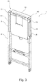
- the Fig. 3 shows a second variant of the installation element 1 in a perspective view.
- the second variant of the installation element 1 differs from the first variant of the installation element 1 in that the second reinforcement profile 17 extends into the frame base 4.
- the first stiffening profile 16 can also extend into the frame lower part 4, even if this is the case in the case of the Fig. 3 shown second variant of the installation element 1 is not shown.
- the cover 18 at its longitudinal ends a first recess 40 and a second recess 41 (also in Fig. 1 to recognize), so that the first frame profile 6 without interruption up to the first wall connection 10 and the second frame profile 7 without interruption up to the second wall connection 11 can extend.
- the first variant of the installation element 1 is identical to the second variant of the installation element 1.
- the proposed installation element is characterized in particular by a high stability, low weight and low installation costs.
Landscapes
- Health & Medical Sciences (AREA)
- Life Sciences & Earth Sciences (AREA)
- Engineering & Computer Science (AREA)
- Hydrology & Water Resources (AREA)
- Public Health (AREA)
- Water Supply & Treatment (AREA)
- Sanitary Device For Flush Toilet (AREA)
- Assembled Shelves (AREA)
Abstract
Description
- Die vorliegende Erfindung betrifft ein Installationselement zur Befestigung eines Toilettenbeckens an einer Wand. Mit solchen Installationselementen sind Toilettenbecken und Spülkästen zur Aufnahme einer Spülflüssigkeit für das Toilettenbecken an der Wand sicher befestigbar.
- Bekannte Installationselemente weisen einen Rahmen auf, an dem das Toilettenbecken und der Spülkasten mit einer Vielzahl von Befestigungsmitteln wie Gewindestangen, Schrauben und/oder Muttern befestigbar sind. Der Montageaufwand solcher Installationselemente ist daher vergleichsweise hoch. Zudem sind zur Montage der Installationselemente eine Vielzahl unterschiedlicher Werkzeugen von Nöten. Der Rahmen besteht bei bekannten Installationselementen insbesondere aus verschweißten Stahlrohrprofilen. Die Installationselemente weisen daher regelmäßig zudem ein hohes Gewicht auf, was die Montage der Installationselemente an der Wand weiter erschwert. Darüber hinaus sind Installationselemente mit einem mehrteiligen Rahmen bekannt, die teilweise aus Kunststoff bestehen können. Die bekannten Installationselemente mit mehrteiligen Rahmen weisen jedoch einen noch höheren Montageaufwand auf und können zudem häufig die hohen Stabilitätsanforderungen, insbesondere was deren Biegesteifigkeiten anbelangt, nicht erfüllen.
- Aufgabe der Erfindung ist daher, die mit Bezug auf den Stand der Technik geschilderten Probleme zumindest teilweise zu lösen und insbesondere ein Installationselement zur Befestigung eines Toilettenbeckens an einer Wand anzugeben, das eine hohe Stabilität, ein geringes Gewicht und einen geringen Montageaufwand aufweist.
- Diese Aufgaben werden gelöst mit einem Installationselement gemäß den Merkmalen des unabhängigen Patentanspruchs. Weitere vorteilhafte Ausgestaltungen des Installationselements sind in den abhängig formulierten Patentansprüchen angegeben. Es ist darauf hinzuweisen, dass die in den abhängig formulierten Patentansprüchen einzeln aufgeführten Merkmale in beliebiger technologisch sinnvoller Weise miteinander kombiniert werden können und weitere Ausgestaltungen der Erfindung definieren. Darüber hinaus werden die in den Patentansprüchen angegebenen Merkmale in der Beschreibung näher präzisiert und erläutert, wobei weitere bevorzugte Ausgestaltungen der Erfindung dargestellt werden.
- Das erfindungsgemäße Installationselement zur Befestigung eines Toilettenbeckens an einer Wand weist einen Spülkasten zur Aufnahme einer Spülflüssigkeit für das Toilettenbecken und einen Rahmen auf, mit dem das Toilettenbecken und der Spülkasten an der Wand befestigbar sind, wobei der Rahmen ein Rahmenunterteil und ein Rahmenoberteil aufweist, wobei das Rahmenoberteil ein formschlüssig mit dem Spülkasten verbundenes erstes Rahmenprofil und ein formschlüssig mit dem Spülkasten verbundenes zweites Rahmenprofil umfasst und wobei das erste Rahmenprofil in Richtung einer ersten Längsachse des ersten Rahmenprofils und das zweite Rahmenprofil in Richtung einer zweiten Längsachse des zweiten Rahmenprofils zumindest teilweise einen sich ändernden Querschnitt aufweist.
- Das Installationselement dient der Befestigung eines Toilettenbeckens und eines Spülkastens zur Aufnahme einer Spülflüssigkeit für das Toilettenbecken an einer Wand. Mittels solcher Installationselemente können Toilettenbecken insbesondere an Leichtbauwänden befestigt werden, die für eine direkte Befestigung des Toilettenbeckens nicht geeignet sind.
- Der Spülkasten besteht insbesondere zumindest teilweise aus Kunststoff und/oder ist mittels eines Kunststoffspritzgussverfahrens hergestellt. Weiterhin weist der Spülkasten einen Aufnahmeraum für die Spülflüssigkeit auf, wobei es sich bei der Spülflüssigkeit insbesondere um Wasser handelt. Zur Spülung des Toilettenbeckens ist mit einer Betätigungsvorrichtung, beispielsweise einem an der Wand angeordneten Spülknopf, ein Ventil des Spülkastens betätigbar. Beim Spülen des Toilettenbeckens wird die Spülflüssigkeit dem Toilettenbecken über einen Spülflüssigkeitsauslass des Spülkastens zugeführt, der regelmäßig am Boden des Aufnahmeraums angeordnet ist.
- Das Toilettenbecken und der Spülkasten sind an einem Rahmen des Installationselements befestigbar, wobei der Rahmen ein Rahmenunterteil und ein Rahmenoberteil umfasst. Das Rahmenunterteil kann Füße aufweisen, mit denen der Rahmen auf einem Boden, beispielsweise mittels Schraubverbindungen, befestigbar ist. Weiterhin kann das Rahmenoberteil an einem der Füße gegenüber liegenden Ende Wandanbindungen aufweisen, mittels denen der Rahmen an der Wand, beispielweise mit Schraubverbindungen, befestigbar ist.
- Das Rahmenoberteil umfasst ein formschlüssig mit dem Spülkasten verbundenes erstes Rahmenprofil und ein formschlüssig mit dem Spülkasten verbundenes zweites Rahmenprofil. Formschlüssig verbunden bedeutet insbesondere, dass der Spülkasten, das erste Rahmenprofil und das zweite Rahmenprofil (zusammen) einstückig ausgebildet sind. Hierzu können das erste Rahmenprofil und das zweite Rahmenprofil insbesondere während des Herstellungsprozesses des Spülkastens an den Spülkasten angespritzt werden. Weiterhin können das erste Rahmenprofi, das zweite Rahmenprofil und der Spülkasten gemeinsam mit dem Kunststoffspritzgussverfahren hergestellt werden. Hierdurch sind für die Befestigung des ersten Rahmenprofils und des zweiten Rahmenprofils an dem Spülkasten keine zusätzlichen Befestigungsmittel und kein zusätzliches Werkzeug erforderlich, wodurch sich der Montageaufwand reduziert. Das erste Rahmenprofil und das zweite Rahmenprofil weisen insbesondere einen (vollständig) geraden Verlauf und/oder orthogonal zur ihrer ersten Längsachse oder zweiten Längsachse einen rechteckigen Querschnitt auf. Weiterhin sind das erste Rahmenprofil und das zweite Rahmenprofil insbesondere spiegelsymmetrisch zueinander ausgestaltet.
- Weiterhin weist das erste Rahmenprofil in Richtung der ersten Längsachse des ersten Rahmenprofils und das zweite Rahmenprofil in Richtung der zweiten Längsachse des zweiten Rahmenprofils zumindest teilweise einen sich ändernden Querschnitt auf. Dies bedeutet insbesondere, dass sich eine Fläche des Querschnitts zumindest teilweise (kontinuierlich) ändert, nicht konstant ist und/oder variabel ist. Als Querschnitt wird insbesondere eine (gedachte) Schnittfläche durch das erste Rahmenprofil und/oder zweite Rahmenprofil verstanden, die insbesondere orthogonal zu der ersten Längsrichtung und/oder zweiten Längsrichtung verläuft. Wird die Schnittfläche in Richtung der ersten Längsachse und/oder der zweiten Längsachse verschoben, verändert sich der jeweilige Querschnitt in zumindest einer Richtung, insbesondere in einer Tiefenrichtung und/oder einer Breitenrichtung des Installationselements. Die Tiefenrichtung verläuft insbesondere orthogonal zu der ersten Längsrichtung, zweiten Längsrichtung und der Breitenrichtung des Installationselements. Zudem verlaufen die Tiefenrichtung des Installationselements nach der Montage des Installationselements an einer Wand insbesondere horizontal und/oder senkrecht zu der Wand und die Breitenrichtung insbesondere parallel zu der Wand. Das erste Rahmenprofil und/oder das zweite Rahmenprofil sind somit querschnittveränderlich insbesondere in einer oder zwei Richtungen. Der Querschnitt kann zudem insbesondere im Wesentlichen (stets) rechteckförmig sein. Der Querschnitt des ersten Rahmenprofils und/oder des zweiten Rahmenprofils ändert sich in Richtung der ersten Längsachse beziehungsweise in Richtung der zweiten Längsachse insbesondere über eine Strecke von 100 mm (Millimeter) bis 800 mm. Weiterhin befindet sich diese Strecke des sich ändernden Querschnitts insbesondere in einem Bereich des ersten Rahmenprofils und/oder zweiten Rahmenprofils, der einen geraden Verlauf aufweist. Die Strecke des sich ändernden Querschnitts befindet sich daher insbesondere nicht in gebogenen oder gekrümmten Bereichen des ersten Rahmenprofils und zweiten Rahmenprofils sowie insbesondere nicht an Ecken des Rahmenoberteils. Durch sich die ändernden Querschnitte des ersten Rahmenprofils und des zweiten Rahmenprofils sind das erste Rahmenprofil und das zweite Rahmenprofil gezielt auf die zu erwartenden Biegebeanspruchungen einstellbar und somit das Gewicht des Rahmens optimierbar. Das erste Rahmenprofil und das zweite Rahmenprofil können somit in Relation zu ihrer Masse besonders biegesteif ausgebildet werden. Weiterhin können das erste Rahmenprofil und das zweite Rahmenprofil im Sinne von "Trägern gleicher Biegebeanspruchung" gestaltet werden.
- Ebenfalls vorteilhaft ist es, wenn sich der Querschnitt des ersten Rahmenprofils in Richtung einer ersten Wandanbindung und der Querschnitt des zweiten Rahmprofils in Richtung einer zweiten Wandanbindung verjüngen. Die Verjüngung erfolgt dabei in zumindest eine Richtung, beispielsweise in der Tiefenrichtung und/oder der Breitenrichtung des Installationselements. Die Verjüngung in der Breitenrichtung des Installationselements erlaubt dabei insbesondere eine günstige Formgestaltung für den Kunststoffspritzguss. Bei der ersten Wandanbindung und der zweiten Wandanbindung kann es sich jeweils insbesondere um Bohrungen in dem ersten Rahmenprofil und dem zweiten Rahmenprofil, insbesondere an einem längsseitigen Ende des ersten Rahmenprofils und zweiten Rahmenprofils, handeln, an denen Wandanbindungselemente zur Befestigung des Rahmens an der Wand befestigbar sind. Der Querschnitt des ersten Rahmenprofils und/oder des zweiten Rahmenprofils kann sich dabei in zumindest eine Dimension (insbesondere orthogonal zu der ersten Längsachse und/oder zweiten Längsachse) von einer Länge von ca. 50 mm bis 100 mm auf eine Länge von ca. 20 mm auf 50 mm verjüngen. Weiterhin kann sich die Fläche des Querschnitts des ersten Rahmenprofils in Richtung der ersten Längsachse und/oder die Fläche des Querschnitts des zweiten Rahmenprofils in Richtung der zweiten Längsachse um 20 % bis 80 % ändern.
- Zudem ist es vorteilhaft, wenn das erste Rahmenprofil mit einer ersten Steckverbindung und das zweite Rahmenprofil mit einer zweiten Steckverbindung mit dem Rahmenunterteil verbindbar sind. Hierzu kann das erste Rahmenprofil einen ersten Verbindungsabschnitt und das zweite Rahmenprofil einen zweiten Verbindungsabschnitt aufweisen, mit denen das erste Rahmenprofil und das zweite Rahmenprofil in das Rahmenunterteil einsteckbar sind. Das erste Rahmenprofil und das zweite Rahmenprofil sind insbesondere bis zum Erreichen einer ersten Auflagefläche beziehungsweise zweiten Auflagefläche in das Rahmenunterteil einsteckbar. Für eine spielfreie Verbindung des ersten Rahmenprofils und des zweiten Rahmenprofils mit dem Rahmenunterteil können zusätzlich zum Beispiel Schraubverbindungen, Rastverbindungen und/oder andere spannbare Verbindungen eingesetzt werden. Zudem können die erste Steckverbindung und/oder die zweite Steckverbindung auch als teleskopierbare Verbindung ausgeführt sein, sodass eine Höhenverstellung des Rahmenoberteils beziehungsweise einer Rahmenoberkante ermöglicht ist. Weiterhin sind die erste Steckverbindung und die zweite Steckverbindung insbesondere derart ausgestaltet, dass eine Montage des Rahmens sowohl im Werk des Herstellers als auch auf einer Baustelle ausgeführt werden kann. Hierdurch kann der Rahmen sowohl montiert als auch geteilt ausgeliefert werden.
- Weiterhin ist es vorteilhaft, wenn das erste Rahmenprofil an einer ersten Seite des Spülkastens angeordnet ist und das zweite Rahmenprofil an einer zweiten Seite des Spülkastens angeordnet ist und wobei sich die erste Seite und die zweite Seite gegenüberliegen. In einem an der Wand montierten Zustand des Installationselements handelt es sich bei der ersten Seite insbesondere um eine rechte Seite des Spülkastens und bei der zweiten Seite insbesondere um eine linke Seite des Spülkastens. Hierdurch befindet sich der Aufnahmeraum für die Spülflüssigkeit des Spülkastens insbesondere zwischen dem ersten Rahmenprofil und dem zweiten Rahmenprofil.
- Vorzugsweise bestehen das Rahmenunterteil zumindest teilweise aus Metall und das Rahmenoberteil zumindest teilweise aus Kunststoff. Das Rahmenunterteil besteht bevorzugt im Wesentlichen aus verschweißten Profilrohren, die insbesondere einen konstanten (rechteckigen) Querschnitt aufweisen.
- Ebenfalls vorteilhaft ist es, wenn das erste Rahmenprofil und das zweite Rahmenprofil eine Rippenstruktur oder eine Wabenstruktur aufweisen. Bei der Rippenstruktur handelt es sich vorzugsweise um eine Kreuzverrippung. Hierdurch kann die Masse des Rahmens des Installationselements weiter reduziert werden, wobei gleichzeitig eine hohe Biegesteifigkeit des Rahmens erhalten bleibt.
- Besonders vorteilhaft ist es, wenn das erste Rahmenprofil ein erstes Versteifungsprofil und das zweite Rahmenprofil ein zweites Versteifungsprofil aufweisen. Durch das erste Versteifungsprofil und das zweite Versteifungsprofil ist die Biegesteifigkeit des Rahmenoberteils weiter erhöhbar. Vorzugsweise erstreckt sich das erste Versteifungsprofil von dem ersten Rahmenprofil in das Rahmenunterteil und/oder das zweite Versteifungsprofil von dem zweiten Rahmenprofil in das Rahmenunterteil. Insbesondere können sich das erste Versteifungsprofil und/oder das zweite Versteifungsprofil in Rechteckrohre des Rahmenunterteils erstrecken. Das erste Versteifungsprofil und das zweite Versteifungsprofil können dadurch in vorteilhafter Weise eine Doppelfunktion erfüllt: nämlich erstens eine deutliche Verbesserung der Biegesteifigkeit des Rahmenoberteils und zweitens die Aufnahme von Befestigungsschrauben für zumindest eine Verkleidungsplatte des Installationselements.
- Zudem ist es vorteilhaft, wenn das erste Versteifungsprofil mit einer ersten Rastverbindung oder ersten Schnappverbindung an dem ersten Rahmenprofil und das zweite Versteifungsprofil mit einer zweiten Rastverbindung oder ersten Schnappverbindung an dem zweiten Rahmenprofil befestigt sind. Hierdurch ist zur Befestigung des ersten Versteifungsprofils an dem ersten Rahmenprofil und des zweiten Versteifungsprofils an dem zweiten Rahmenprofil kein Werkzeug erforderlich. Alternativ können die beiden Versteifungsprofile bei einer Herstellung mittels Spritzgiessens, vorzugsweise mittels Kunststoffspitzgiessens, mit eingespritzt bzw. umspritzt werden.
- Vorzugsweise besteht das erste Versteifungsprofil und das zweite Versteifungsprofil aus Metall und weisen einen L-förmigen oder U-förmigen Querschnitt auf. Das erste Versteifungsprofil und das zweite Versteifungsprofil bestehen insbesondere aus einem (in einem 90° Winkel) gebogenen Metallblech.
- Weiterhin ist es vorteilhaft, wenn der Spülkasten einen Deckel umfasst, der ein drittes Versteifungsprofil aufweist. Mittels des Deckels ist der Aufnahmeraum für das Spülwasser des Spülkastens insbesondere zumindest teilweise abdeckbar. Hierzu erstreckt sich der Deckel insbesondere von dem ersten Rahmenprofil zu dem zweiten Rahmenprofil. Im montierten Zustand des Installationselements erstreckt sich der Deckel insbesondere waagerecht. Das dritte Versteifungsprofil besteht bevorzugt aus Metall, insbesondere Metallblech und/oder weist einen L-förmigen Querschnitt auf. Das dritte Versteifungsprofil kann (gegebenenfalls mit Ausnahme seiner Länge) identisch zu dem ersten Versteifungsprofil und dem zweiten Versteifungsprofil ausgebildet werden. Weiterhin kann der Deckel an seinen längsseitigen Enden, insbesondere an einer (vorderen) Außenkante, Aussparrungen aufweisen, sodass das erste Rahmenprofil und das zweite Rahmenprofil, die statisch tragend sind, ohne Unterbrechungen bis zu den Wandanbindungen durchlaufend ausführbar sind. Weiterhin kann der Deckel durch eine Verrippung und/oder ein weiteres Versteifungsprofil, das beispielsweise am Deckel eingerastet oder seitlich in den Deckel eingeschoben ist, verstärkt und belastbar mit dem Rahmenoberteil verbunden sein, sodass insbesondere auf eine bei bekannten Installationselementen erforderliche Kopftraverse verzichtet werden kann.
- Die Erfindung sowie das technische Umfeld werden nachfolgend anhand der Figuren näher erläutert. Es ist darauf hinzuweisen, dass die Figuren eine besonders bevorzugte Ausführungsvariante der Erfindung zeigen, diese jedoch nicht darauf beschränkt ist. Dabei sind gleiche Bauteile in den Figuren mit denselben Bezugszeichen versehen. Es zeigen beispielhaft und schematisch:
- Fig. 1:
- eine erste Variante eines Installationselements in einer perspektivischen Darstellung;
- Fig. 2:
- einen Spülkasten der ersten Variante des Installationselements in einer perspektivischen Darstellung; und
- Fig. 3:
- eine zweite Variante eines Installationselements in einer perspektivischen Darstellung.
- Die
Fig. 1 zeigt eine erste Variante eines Installationselements 1 in einer perspektivischen Darstellung. Das Installationselement 1 umfasst einen Rahmen 3, mittels dem ein hier nicht gezeigtes Toilettenbecken und ein Spülkasten 2 an einer hier ebenfalls nicht gezeigten Wand befestigbar sind. Der Rahmen 3 umfasst ein Rahmenunterteil 4 und ein Rahmenoberteil 5. Das Rahmenunterteil 4 weist ein erstes Profilrohr 26 und ein zweites Profilrohr 27 auf, die über eine erste Quertraverse 20 und eine zweite Quertraverse 21 miteinander verbunden sind. Das Toilettenbecken ist insbesondere über eine Schraubverbindung an der ersten Quertraverse 20 befestigbar. Das erste Profilrohr 26 erstreckt sich entlang einer ersten Längsachse 8 und das zweite Profilrohr 27 entlang einer zweiten Längsachse 9. An einem ersten längsseitigen Ende 22 des ersten Profilrohrs 26 weist das erste Profilrohr 26 einen ersten Fuß 24 auf. Entsprechend weist das zweite Profilrohr 27 an einem zweiten längsseitigen Ende 23 einen zweiten Fuß 25 auf. Der erste Fuß 24 ist in dem ersten Profilrohr 26 und der zweite Fuß 25 in dem zweiten Profilrohr 27 führbar und sind parallel zu der ersten Längsachse 8 und der zweiten Längsachse 9 zur Einstellung einer Höhe des Installationselements 1 verstellbar. Mittels des ersten Fußes 24 und des zweiten Fußes 25 ist der Rahmen 3 auf einem hier nicht gezeigten Boden befestigbar. - Der Spülkasten 2 weist einen Aufnahmeraum 33 für eine Spülflüssigkeit auf, der durch einen Deckel 18 zumindest teilweise verschließbar ist. Zudem ist ein hier nicht gezeigtes Ventil des Spülkastens 2 zum Spülen des Toilettenbeckens durch ein hier ebenfalls nicht gezeigtes Betätigungselement betätigbar, wodurch die Spülflüssigkeit über einen Spülflüssigkeitsauslass 28 des Spülkastens 2 zu dem Toilettenbecken leitbar ist.
- Weiterhin weist der Spülkasten 2 auf einer ersten Seite 14 ein formschlüssig mit dem Spülkasten 2 verbundenes erstes Rahmenprofil 6 und an einer zweiten Seite 15 ein formschlüssig mit dem Spülkasten 2 verbundenes zweites Rahmenprofil 7 auf. Das erste Rahmenprofil 6 ist mit einem ersten Versteifungsprofil 16 und das zweite Rahmenprofil 7 mit einem zweiten Versteifungsprofil 17 versteift. Hierzu ist das erste Versteifungsprofil 16 mit einer Schnappverbindung an dem ersten Rahmenprofil 6 und das zweite Versteifungsprofil 17 mit einer Schnappverbindung an dem zweiten Rahmenprofil 7 befestigbar. Zudem ist der Deckel 18 des Spülkastens 2 mit einem dritten Versteifungsprofil 19 versteift, das ebenfalls mit einer Schnappverbindung an dem Deckel 18 befestigbar ist. Das erste Versteifungsprofil 16, das zweite Versteifungsprofil 17 und das dritte Versteifungsprofil 19 erfüllen eine Doppelfunktion. Sie führen einerseits zu einer deutlichen Verbesserung der Biegesteifigkeit des Rahmenoberteils 5 und dienen andererseits als Aufnahme für Befestigungsschrauben einer hier nichtgezeigten Verkleidungsplatte des Installationselements 1. Das erste Rahmenprofil 6 ist mit einer ersten Steckverbindung 12 und das zweite Rahmenprofil 7 mit einer zweiten Steckverbindung 13 an dem Rahmenunterteil 4 befestigbar. Hierzu ist ein in der
Fig. 2 gezeigter erster Verbindungsabschnitt 31 des ersten Rahmenprofils 6 in das erste Profilrohr 26 und ein in derFig. 2 gezeigter zweiter Verbindungsabschnitt 32 des zweiten Rahmenprofils 7 in das zweite Profilrohr 27 einsteckbar. - Die
Fig. 2 zeigt eine perspektivische Darstellung des Spülkastens 2 der in derFig. 1 gezeigten ersten Variante des Installationselements 1. Zu erkennen ist hier insbesondere, dass das erste Rahmenprofil 6 entlang der ersten Längsachse 8 und das zweite Rahmenprofil 7 entlang der zweiten Längsachse 9 einen sich ändernden Querschnitt aufweisen, wobei in derFig. 2 exemplarisch nur ein erster Querschnitt 39 und ein zweiter Querschnitt 42 des ersten Rahmenprofils 6 mit gestrichelten Linien dargestellt sind. Bei dem ersten Querschnitt 39 und dem zweiten Querschnitt 42 handelt es sich um (gedachte) Schnittflächen des ersten Rahmenprofils 6, die durch eine Tiefenrichtung 37 und eine Breitenrichtung 38 des Spülkastens 2 beziehungsweise des in derFig. 1 gezeigten Installationselements 1 aufgespannt werden. Der erste Querschnitt 39 und der zweite Querschnitt 42 sind bei der hier gezeigten Variante rechteckförmig. Bei einer Verschiebung des ersten Querschnitts 39 in Richtung der ersten Längsachse 8 ändert sich dessen Querschnittsfläche. So weist der zweite Querschnitt 42 in der Tiefenrichtung 37 und in der Breitenrichtung 38 eine geringere Länge auf als der erste Querschnitt 39. Entsprechendes gilt für das zweite Rahmenprofil 7. Dies bedeutet, dass sich das erste Rahmenprofil 6 und das zweite Rahmenprofil 7 in zwei Richtungen verjüngen, wobei die Verjüngung in der Breitenrichtung 38 besonders vorteilhaft für den Entformungsprozess beim Kunststoffspritzgussverfahren ist. An einem längsseitigen Ende des ersten Verbindungsabschnitts 31 weist das erste Rahmenprofil 6 zudem eine orthogonal zu der ersten Längsachse 8 verlaufende erste Auflagefläche 34 auf, mit der das erste Rahmenprofil 6 auf einem stirnseitigen Ende des ersten Profilrohrs 26 aufliegt, wenn das erste Rahmenprofil 6 in das erste Profilrohr 26 eingesteckt ist. Entsprechend weist das zweite Rahmenprofil 7 an dem längsseitigen Ende des zweiten Verbindungsabschnitts 32 eine orthogonal zu der zweiten Längsachse 9 verlaufende zweite Auflagefläche 35 auf, mit der das zweite Rahmenprofil 7 auf einer längsseitigen Stirnfläche des zweiten Profilrohrs 27 aufliegt, wenn das zweite Rahmenprofil 7 in das zweite Profilrohr 27 eingesteckt ist. Der Querschnitt des ersten Rahmenprofils 6 verjüngt sich ausgehend von der ersten Auflagefläche 34 parallel zu der ersten Längsachse 8 in Richtung einer ersten Wandanbindung 10. Entsprechend verjüngt sich der Querschnitt des zweiten Rahmenprofils 7 ausgehend von der zweiten Auflagefläche 35 in Richtung einer zweiten Wandanabindung 11. Die erste Wandanbindung 10 und die zweite Wandanbindung 11 sind hier in Form von Bohrungen ausgeführt, an die hier nicht gezeigte Wandanbindungselemente befestigbar sind. Das erste Rahmenprofil 6 weist einen umlaufenden äußeren Außenrahmen 29 auf, in dem eine Rippenstruktur 30 mit Rippen 36 zur Erhöhung der Biegesteifigkeit des ersten Rahmenprofils 6 ausgebildet ist. Diese ist bei der hier gezeigten Ansicht beim zweiten Rahmenprofil 7 nicht sichtbar. Das erste Rahmenprofil 6 und das zweite Rahmenprofil 7 sind jedoch spiegelsymmetrisch ausgebildet, sodass die Beschreibung des ersten Rahmenprofils 6 entsprechend auf das zweite Rahmenprofil 7 übertragbar ist. - Die
Fig. 3 zeigt eine zweite Variante des Installationselements 1 in einer perspektivischen Darstellung. Die zweite Variante des Installationselements 1 unterscheidet sich von der ersten Variante des Installationselements 1 dadurch, dass sich das zweite Versteifungsprofil 17 bis in das Rahmenunterteil 4 erstreckt. Ebenfalls kann sich auch das erste Versteifungsprofil 16 bis in das Rahmenunterteil 4 erstrecken, auch wenn dies bei der inFig. 3 gezeigten zweiten Variante des Installationselements 1 nicht gezeigt ist. Weiterhin weist der Deckel 18 an seinen längsseitigen Enden eine erste Aussparung 40 und eine zweite Aussparung 41 auf (ebenfalls inFig. 1 zu erkennen), sodass sich das erste Rahmenprofil 6 ohne Unterbrechung bis zu der ersten Wandanbindung 10 und das zweite Rahmenprofil 7 ohne Unterbrechung bis zu der zweiten Wandanbindung 11 erstrecken können. Die erste Variante des Installationselements 1 ist im Übrigen identisch zu der zweiten Variante des Installationselements 1 ausgebildet. - Das vorgeschlagene Installationselement zeichnet sich insbesondere durch eine hohe Stabilität, ein geringes Gewicht und einen geringen Montageaufwand aus.
-
- 1
- Installationselement
- 2
- Spülkasten
- 3
- Rahmen
- 4
- Rahmenunterteil
- 5
- Rahmenoberteil
- 6
- erstes Rahmenprofil
- 7
- zweites Rahmenprofil
- 8
- erste Längsachse
- 9
- zweite Längsachse
- 10
- erste Wandanbindung
- 11
- zweite Wandanbindung
- 12
- erste Steckverbindung
- 13
- zweite Steckverbindung
- 14
- erste Seite
- 15
- zweite Seite
- 16
- erstes Versteifungsprofil
- 17
- zweites Versteifungsprofil
- 18
- Deckel
- 19
- drittes Versteifungsprofil
- 20
- erste Quertraverse
- 21
- zweite Quertraverse
- 22
- erstes längsseitiges Ende
- 23
- zweites längsseitiges Ende
- 24
- erster Fuß
- 25
- zweiter Fuß
- 26
- erstes Profilrohr
- 27
- zweites Profilrohr
- 28
- Spülflüssigkeitsauslass
- 29
- Außenrahmen
- 30
- Rippenstruktur
- 31
- erster Verbindungsabschnitt
- 32
- zweiter Verbindungsabschnitt
- 33
- Aufnahmeraum
- 34
- erste Auflagefläche
- 35
- zweite Auflagefläche
- 36
- Rippen
- 37
- Tiefenrichtung
- 38
- Breitenrichtung
- 39
- erster Querschnitt
- 40
- erste Aussparung
- 41
- zweite Aussparung
- 42
- zweiter Querschnitt
Claims (10)
- Installationselement (1) zur Befestigung eines Toilettenbeckens an einer Wand, aufweisend einen Spülkasten (2) zur Aufnahme einer Spülflüssigkeit für das Toilettenbecken und einen Rahmen (3), mit dem das Toilettenbecken und der Spülkasten (2) an der Wand befestigbar sind, wobei der Rahmen (3) ein Rahmenunterteil (4) und ein Rahmenoberteil (5) aufweist, wobei das Rahmenoberteil (5) ein formschlüssig mit dem Spülkasten (2) verbundenes erstes Rahmenprofil (6) und ein formschlüssig mit dem Spülkasten (2) verbundenes zweites Rahmenprofil (7) umfasst und wobei das erste Rahmenprofil (6) in Richtung einer ersten Längsachse (8) des ersten Rahmenprofils (6) und das zweite Rahmenprofil (7) in Richtung einer zweiten Längsachse (9) des zweiten Rahmenprofils (7) zumindest teilweise einen sich ändernden Querschnitt (39, 42) aufweisen.
- Installationselement (1) nach Patentanspruch 1, wobei sich der Querschnitt (39, 42) des ersten Rahmenprofils (6) in Richtung einer ersten Wandanbindung (10) und der Querschnitt (39, 42) des zweiten Rahmprofils (7) in Richtung einer zweiten Wandanbindung (11) verjüngen.
- Installationselement (1) nach einem der vorhergehenden Patentansprüche, wobei das erste Rahmenprofil (6) mit einer ersten Steckverbindung (12) und das zweite Rahmenprofil (7) mit einer zweiten Steckverbindung (13) mit dem Rahmenunterteil (4) verbindbar sind.
- Installationselement (1) nach einem der vorhergehenden Patentansprüche, wobei das erste Rahmenprofil (6) an einer ersten Seite (14) des Spülkastens (2) angeordnet ist und das zweite Rahmenprofil (7) an einer zweiten Seite (15) des Spülkastens (2) angeordnet ist und wobei sich die erste Seite (14) und die zweite Seite (15) gegenüberliegen.
- Installationselement (1) nach einem der vorhergehenden Patentansprüche, wobei das Rahmenunterteil (4) zumindest teilweise aus Metall und das Rahmenoberteil (5) zumindest teilweise aus Kunststoff bestehen.
- Installationselement (1) nach einem der vorhergehenden Patentansprüche, wobei das erste Rahmenprofil (6) und das zweite Rahmenprofil (7) eine Rippenstruktur (30) oder eine Wabenstruktur aufweisen.
- Installationselement (1) nach einem der vorhergehenden Patentansprüche, wobei das erste Rahmenprofil (6) ein erstes Versteifungsprofil (16) und das zweite Rahmenprofil (7) ein zweites Versteifungsprofil (17) aufweisen.
- Installationselement (1) nach Patentanspruch 7, wobei das erste Versteifungsprofil (16) mit einer ersten Rastverbindung oder ersten Schnappverbindung an dem ersten Rahmenprofil (6) und das zweite Versteifungsprofil (17) mit einer zweiten Rastverbindung oder zweiten Schnappverbindung an dem zweiten Rahmenprofil (7) befestigt sind.
- Installationselement (1) nach Patentanspruch 7 oder 8, wobei das erste Versteifungsprofil (16) und das zweite Versteifungsprofil (17) aus Metall bestehen und einen L-förmigen oder U-förmigen Querschnitt aufweisen.
- Installationselement (1) nach einem der vorhergehenden Patentansprüche, wobei der Spülkasten (2) einen Deckel (18) umfasst, der ein drittes Versteifungsprofil (19) aufweist.
Applications Claiming Priority (2)
| Application Number | Priority Date | Filing Date | Title |
|---|---|---|---|
| DE102017005090 | 2017-05-29 | ||
| DE102017009257.5A DE102017009257A1 (de) | 2017-05-29 | 2017-10-05 | Installationselement zur Befestigung eines Toilettenbeckens an einer Wand mit tragenden querschnittveränderlichen Rahmenprofilen |
Publications (2)
| Publication Number | Publication Date |
|---|---|
| EP3415696A1 true EP3415696A1 (de) | 2018-12-19 |
| EP3415696B1 EP3415696B1 (de) | 2020-02-12 |
Family
ID=64109095
Family Applications (1)
| Application Number | Title | Priority Date | Filing Date |
|---|---|---|---|
| EP18174329.5A Active EP3415696B1 (de) | 2017-05-29 | 2018-05-25 | Installationselement zur befestigung eines toilettenbeckens an einer wand mit tragenden querschnittveränderlichen rahmenprofilen |
Country Status (3)
| Country | Link |
|---|---|
| EP (1) | EP3415696B1 (de) |
| CN (1) | CN108930317B (de) |
| DE (1) | DE102017009257A1 (de) |
Cited By (3)
| Publication number | Priority date | Publication date | Assignee | Title |
|---|---|---|---|---|
| EP3715546A1 (de) | 2019-03-29 | 2020-09-30 | Grohe AG | Rahmenkonstruktion für ein sanitärelement |
| WO2022155996A1 (zh) * | 2021-01-20 | 2022-07-28 | 厦门融技精密科技有限公司 | 一种能够加长调节范围的固定机构 |
| CN115680076A (zh) * | 2022-10-31 | 2023-02-03 | 浙江亚厦装饰股份有限公司 | 一种壁挂式马桶水箱钢架的加固结构 |
Families Citing this family (1)
| Publication number | Priority date | Publication date | Assignee | Title |
|---|---|---|---|---|
| AT522573B1 (de) * | 2019-12-10 | 2020-12-15 | Andre Rathammer | Anordnung für die Installation und Montage eines Waschbecken |
Citations (4)
| Publication number | Priority date | Publication date | Assignee | Title |
|---|---|---|---|---|
| FR2868097A1 (fr) * | 2004-03-24 | 2005-09-30 | Delabie Sa Sa | Bati-support pour appareils sanitaires |
| DE202006011801U1 (de) * | 2006-08-01 | 2006-09-28 | Mayr, Frank | Rahmenkonstruktion für die Montage eines Sanitärgegenstandes |
| EP2166163A1 (de) * | 2008-09-17 | 2010-03-24 | Geberit International AG | Montageeinrichtung für eine WC-Schüssel |
| WO2016162352A1 (fr) * | 2015-04-10 | 2016-10-13 | Siamp Cedap | Structure de support pour un équipement de toilettes suspendues |
Family Cites Families (7)
| Publication number | Priority date | Publication date | Assignee | Title |
|---|---|---|---|---|
| DE19836634C2 (de) * | 1998-08-13 | 2002-02-07 | Friatec Ag | Befestigungsanordnung eines Spülkastens |
| CN101358460B (zh) * | 2007-08-01 | 2010-06-30 | 陆丰科 | 新型多洁卫具组合装置 |
| IT1398848B1 (it) * | 2010-03-16 | 2013-03-21 | Raccorderie Metalliche Spa | Telaio per fissare sanitari a muro |
| ES2616578T3 (es) * | 2012-05-09 | 2017-06-13 | Geberit International Ag | Dispositivo de montaje para la fijación de un aparato sanitario |
| CN202610915U (zh) * | 2012-10-11 | 2012-12-19 | 东陶华东有限公司 | 隐蔽水箱 |
| DK3071757T3 (da) * | 2014-05-26 | 2020-09-21 | Geberit Int Ag | Arrangement med en monteringsramme og en sanitær der er monteret på monteringsrammen |
| TR201908810T4 (tr) | 2015-03-11 | 2019-07-22 | Nicoll Raccords Plastiques | Destek çerçevesi için sabitleme cihazı, böyle bir cihaz içeren sabitleme tertibatı ve bir destek çerçevesi üzerinde sabitleme yöntemi. |
-
2017
- 2017-10-05 DE DE102017009257.5A patent/DE102017009257A1/de not_active Withdrawn
-
2018
- 2018-05-25 EP EP18174329.5A patent/EP3415696B1/de active Active
- 2018-05-29 CN CN201810531005.5A patent/CN108930317B/zh active Active
Patent Citations (4)
| Publication number | Priority date | Publication date | Assignee | Title |
|---|---|---|---|---|
| FR2868097A1 (fr) * | 2004-03-24 | 2005-09-30 | Delabie Sa Sa | Bati-support pour appareils sanitaires |
| DE202006011801U1 (de) * | 2006-08-01 | 2006-09-28 | Mayr, Frank | Rahmenkonstruktion für die Montage eines Sanitärgegenstandes |
| EP2166163A1 (de) * | 2008-09-17 | 2010-03-24 | Geberit International AG | Montageeinrichtung für eine WC-Schüssel |
| WO2016162352A1 (fr) * | 2015-04-10 | 2016-10-13 | Siamp Cedap | Structure de support pour un équipement de toilettes suspendues |
Cited By (3)
| Publication number | Priority date | Publication date | Assignee | Title |
|---|---|---|---|---|
| EP3715546A1 (de) | 2019-03-29 | 2020-09-30 | Grohe AG | Rahmenkonstruktion für ein sanitärelement |
| WO2022155996A1 (zh) * | 2021-01-20 | 2022-07-28 | 厦门融技精密科技有限公司 | 一种能够加长调节范围的固定机构 |
| CN115680076A (zh) * | 2022-10-31 | 2023-02-03 | 浙江亚厦装饰股份有限公司 | 一种壁挂式马桶水箱钢架的加固结构 |
Also Published As
| Publication number | Publication date |
|---|---|
| CN108930317A (zh) | 2018-12-04 |
| CN108930317B (zh) | 2020-10-20 |
| EP3415696B1 (de) | 2020-02-12 |
| DE102017009257A1 (de) | 2018-11-29 |
Similar Documents
| Publication | Publication Date | Title |
|---|---|---|
| DE4414462B4 (de) | Beschlag zur Höhenverstellung von Schubladen | |
| EP3415696B1 (de) | Installationselement zur befestigung eines toilettenbeckens an einer wand mit tragenden querschnittveränderlichen rahmenprofilen | |
| EP3548321A1 (de) | Profilleistenanordnung | |
| EP3789550A1 (de) | Rostverriegelungsvorrichtung | |
| EP3009045B1 (de) | Zarge für eine schublade mit einem zargenkörper sowie schublade und möbel mit einer schublade | |
| DE102013101422B3 (de) | Montagesystem zum Abstützen, Befestigen und Positionieren von Bauelementen | |
| EP3149251B1 (de) | Montagevorrichtung | |
| DE102021200375B4 (de) | Dachreling für ein Kraftfahrzeug, Kraftfahrzeug sowie Verfahren zum Herstellen einer Dachreling | |
| DE102018104121B4 (de) | Stütz- und Verstärkungselement, Flachblech, Entwässerungssystem und Verfahren zur Herstellung | |
| DE102008060355B4 (de) | Verbindungsanordnung zum adhäsiven Anbinden eines Faserverbundkunststoff-Profils an eine Leichtmetallstruktur | |
| DE102005057707B4 (de) | A-Säule für ein Kraftfahrzeug | |
| DE102005058106B4 (de) | Untergestell für eine Sanitärwanne | |
| DE202006011801U1 (de) | Rahmenkonstruktion für die Montage eines Sanitärgegenstandes | |
| EP3865640A1 (de) | Putzprofil | |
| EP1990474A2 (de) | Stützfuß für einen Sanitär-Installationsrahmen | |
| DE8704304U1 (de) | Vorgefertigter Rolladenkasten aus aneinanderstoßenden Ziegelformsteinen | |
| DE102011051484A1 (de) | Lichtschachtaufstockelement | |
| AT522090B1 (de) | Schalungsvorrichtung | |
| EP4592464A2 (de) | Montagevorrichtung | |
| DE19748200C2 (de) | Traggestellrahmen zur Montage in einer Sanitärinstallationseinheit | |
| AT15964U1 (de) | Installationsblock | |
| DE102024122609A1 (de) | Schalungssystem für eine Gebäudeöffnung | |
| DE29718314U1 (de) | Entwässerungsrinne | |
| DE2059681A1 (de) | Spindeltreppe | |
| DE102014106705A1 (de) | Tragrahmen und steckbare Verbindung zur Bildung eines Tragrahmens |
Legal Events
| Date | Code | Title | Description |
|---|---|---|---|
| PUAI | Public reference made under article 153(3) epc to a published international application that has entered the european phase |
Free format text: ORIGINAL CODE: 0009012 |
|
| STAA | Information on the status of an ep patent application or granted ep patent |
Free format text: STATUS: THE APPLICATION HAS BEEN PUBLISHED |
|
| AK | Designated contracting states |
Kind code of ref document: A1 Designated state(s): AL AT BE BG CH CY CZ DE DK EE ES FI FR GB GR HR HU IE IS IT LI LT LU LV MC MK MT NL NO PL PT RO RS SE SI SK SM TR |
|
| AX | Request for extension of the european patent |
Extension state: BA ME |
|
| STAA | Information on the status of an ep patent application or granted ep patent |
Free format text: STATUS: REQUEST FOR EXAMINATION WAS MADE |
|
| 17P | Request for examination filed |
Effective date: 20190510 |
|
| RBV | Designated contracting states (corrected) |
Designated state(s): AL AT BE BG CH CY CZ DE DK EE ES FI FR GB GR HR HU IE IS IT LI LT LU LV MC MK MT NL NO PL PT RO RS SE SI SK SM TR |
|
| GRAP | Despatch of communication of intention to grant a patent |
Free format text: ORIGINAL CODE: EPIDOSNIGR1 |
|
| STAA | Information on the status of an ep patent application or granted ep patent |
Free format text: STATUS: GRANT OF PATENT IS INTENDED |
|
| INTG | Intention to grant announced |
Effective date: 20190820 |
|
| GRAS | Grant fee paid |
Free format text: ORIGINAL CODE: EPIDOSNIGR3 |
|
| GRAA | (expected) grant |
Free format text: ORIGINAL CODE: 0009210 |
|
| STAA | Information on the status of an ep patent application or granted ep patent |
Free format text: STATUS: THE PATENT HAS BEEN GRANTED |
|
| AK | Designated contracting states |
Kind code of ref document: B1 Designated state(s): AL AT BE BG CH CY CZ DE DK EE ES FI FR GB GR HR HU IE IS IT LI LT LU LV MC MK MT NL NO PL PT RO RS SE SI SK SM TR |
|
| REG | Reference to a national code |
Ref country code: GB Ref legal event code: FG4D Free format text: NOT ENGLISH |
|
| REG | Reference to a national code |
Ref country code: CH Ref legal event code: EP |
|
| REG | Reference to a national code |
Ref country code: AT Ref legal event code: REF Ref document number: 1232283 Country of ref document: AT Kind code of ref document: T Effective date: 20200215 |
|
| REG | Reference to a national code |
Ref country code: IE Ref legal event code: FG4D Free format text: LANGUAGE OF EP DOCUMENT: GERMAN |
|
| REG | Reference to a national code |
Ref country code: DE Ref legal event code: R096 Ref document number: 502018000749 Country of ref document: DE |
|
| PG25 | Lapsed in a contracting state [announced via postgrant information from national office to epo] |
Ref country code: FI Free format text: LAPSE BECAUSE OF FAILURE TO SUBMIT A TRANSLATION OF THE DESCRIPTION OR TO PAY THE FEE WITHIN THE PRESCRIBED TIME-LIMIT Effective date: 20200212 Ref country code: NO Free format text: LAPSE BECAUSE OF FAILURE TO SUBMIT A TRANSLATION OF THE DESCRIPTION OR TO PAY THE FEE WITHIN THE PRESCRIBED TIME-LIMIT Effective date: 20200512 Ref country code: RS Free format text: LAPSE BECAUSE OF FAILURE TO SUBMIT A TRANSLATION OF THE DESCRIPTION OR TO PAY THE FEE WITHIN THE PRESCRIBED TIME-LIMIT Effective date: 20200212 |
|
| REG | Reference to a national code |
Ref country code: LT Ref legal event code: MG4D |
|
| REG | Reference to a national code |
Ref country code: NL Ref legal event code: MP Effective date: 20200212 |
|
| PG25 | Lapsed in a contracting state [announced via postgrant information from national office to epo] |
Ref country code: GR Free format text: LAPSE BECAUSE OF FAILURE TO SUBMIT A TRANSLATION OF THE DESCRIPTION OR TO PAY THE FEE WITHIN THE PRESCRIBED TIME-LIMIT Effective date: 20200513 Ref country code: HR Free format text: LAPSE BECAUSE OF FAILURE TO SUBMIT A TRANSLATION OF THE DESCRIPTION OR TO PAY THE FEE WITHIN THE PRESCRIBED TIME-LIMIT Effective date: 20200212 Ref country code: IS Free format text: LAPSE BECAUSE OF FAILURE TO SUBMIT A TRANSLATION OF THE DESCRIPTION OR TO PAY THE FEE WITHIN THE PRESCRIBED TIME-LIMIT Effective date: 20200612 Ref country code: SE Free format text: LAPSE BECAUSE OF FAILURE TO SUBMIT A TRANSLATION OF THE DESCRIPTION OR TO PAY THE FEE WITHIN THE PRESCRIBED TIME-LIMIT Effective date: 20200212 Ref country code: LV Free format text: LAPSE BECAUSE OF FAILURE TO SUBMIT A TRANSLATION OF THE DESCRIPTION OR TO PAY THE FEE WITHIN THE PRESCRIBED TIME-LIMIT Effective date: 20200212 Ref country code: BG Free format text: LAPSE BECAUSE OF FAILURE TO SUBMIT A TRANSLATION OF THE DESCRIPTION OR TO PAY THE FEE WITHIN THE PRESCRIBED TIME-LIMIT Effective date: 20200512 |
|
| PG25 | Lapsed in a contracting state [announced via postgrant information from national office to epo] |
Ref country code: NL Free format text: LAPSE BECAUSE OF FAILURE TO SUBMIT A TRANSLATION OF THE DESCRIPTION OR TO PAY THE FEE WITHIN THE PRESCRIBED TIME-LIMIT Effective date: 20200212 |
|
| PG25 | Lapsed in a contracting state [announced via postgrant information from national office to epo] |
Ref country code: ES Free format text: LAPSE BECAUSE OF FAILURE TO SUBMIT A TRANSLATION OF THE DESCRIPTION OR TO PAY THE FEE WITHIN THE PRESCRIBED TIME-LIMIT Effective date: 20200212 Ref country code: CZ Free format text: LAPSE BECAUSE OF FAILURE TO SUBMIT A TRANSLATION OF THE DESCRIPTION OR TO PAY THE FEE WITHIN THE PRESCRIBED TIME-LIMIT Effective date: 20200212 Ref country code: PT Free format text: LAPSE BECAUSE OF FAILURE TO SUBMIT A TRANSLATION OF THE DESCRIPTION OR TO PAY THE FEE WITHIN THE PRESCRIBED TIME-LIMIT Effective date: 20200705 Ref country code: SK Free format text: LAPSE BECAUSE OF FAILURE TO SUBMIT A TRANSLATION OF THE DESCRIPTION OR TO PAY THE FEE WITHIN THE PRESCRIBED TIME-LIMIT Effective date: 20200212 Ref country code: SM Free format text: LAPSE BECAUSE OF FAILURE TO SUBMIT A TRANSLATION OF THE DESCRIPTION OR TO PAY THE FEE WITHIN THE PRESCRIBED TIME-LIMIT Effective date: 20200212 Ref country code: EE Free format text: LAPSE BECAUSE OF FAILURE TO SUBMIT A TRANSLATION OF THE DESCRIPTION OR TO PAY THE FEE WITHIN THE PRESCRIBED TIME-LIMIT Effective date: 20200212 Ref country code: DK Free format text: LAPSE BECAUSE OF FAILURE TO SUBMIT A TRANSLATION OF THE DESCRIPTION OR TO PAY THE FEE WITHIN THE PRESCRIBED TIME-LIMIT Effective date: 20200212 Ref country code: LT Free format text: LAPSE BECAUSE OF FAILURE TO SUBMIT A TRANSLATION OF THE DESCRIPTION OR TO PAY THE FEE WITHIN THE PRESCRIBED TIME-LIMIT Effective date: 20200212 Ref country code: RO Free format text: LAPSE BECAUSE OF FAILURE TO SUBMIT A TRANSLATION OF THE DESCRIPTION OR TO PAY THE FEE WITHIN THE PRESCRIBED TIME-LIMIT Effective date: 20200212 |
|
| REG | Reference to a national code |
Ref country code: DE Ref legal event code: R097 Ref document number: 502018000749 Country of ref document: DE |
|
| PLBE | No opposition filed within time limit |
Free format text: ORIGINAL CODE: 0009261 |
|
| STAA | Information on the status of an ep patent application or granted ep patent |
Free format text: STATUS: NO OPPOSITION FILED WITHIN TIME LIMIT |
|
| 26N | No opposition filed |
Effective date: 20201113 |
|
| PG25 | Lapsed in a contracting state [announced via postgrant information from national office to epo] |
Ref country code: MC Free format text: LAPSE BECAUSE OF FAILURE TO SUBMIT A TRANSLATION OF THE DESCRIPTION OR TO PAY THE FEE WITHIN THE PRESCRIBED TIME-LIMIT Effective date: 20200212 Ref country code: IT Free format text: LAPSE BECAUSE OF FAILURE TO SUBMIT A TRANSLATION OF THE DESCRIPTION OR TO PAY THE FEE WITHIN THE PRESCRIBED TIME-LIMIT Effective date: 20200212 |
|
| PG25 | Lapsed in a contracting state [announced via postgrant information from national office to epo] |
Ref country code: PL Free format text: LAPSE BECAUSE OF FAILURE TO SUBMIT A TRANSLATION OF THE DESCRIPTION OR TO PAY THE FEE WITHIN THE PRESCRIBED TIME-LIMIT Effective date: 20200212 Ref country code: SI Free format text: LAPSE BECAUSE OF FAILURE TO SUBMIT A TRANSLATION OF THE DESCRIPTION OR TO PAY THE FEE WITHIN THE PRESCRIBED TIME-LIMIT Effective date: 20200212 |
|
| REG | Reference to a national code |
Ref country code: BE Ref legal event code: MM Effective date: 20200531 |
|
| PG25 | Lapsed in a contracting state [announced via postgrant information from national office to epo] |
Ref country code: LU Free format text: LAPSE BECAUSE OF NON-PAYMENT OF DUE FEES Effective date: 20200525 |
|
| PG25 | Lapsed in a contracting state [announced via postgrant information from national office to epo] |
Ref country code: FR Free format text: LAPSE BECAUSE OF NON-PAYMENT OF DUE FEES Effective date: 20200531 Ref country code: IE Free format text: LAPSE BECAUSE OF NON-PAYMENT OF DUE FEES Effective date: 20200525 |
|
| PG25 | Lapsed in a contracting state [announced via postgrant information from national office to epo] |
Ref country code: BE Free format text: LAPSE BECAUSE OF NON-PAYMENT OF DUE FEES Effective date: 20200531 |
|
| PG25 | Lapsed in a contracting state [announced via postgrant information from national office to epo] |
Ref country code: TR Free format text: LAPSE BECAUSE OF FAILURE TO SUBMIT A TRANSLATION OF THE DESCRIPTION OR TO PAY THE FEE WITHIN THE PRESCRIBED TIME-LIMIT Effective date: 20200212 Ref country code: MT Free format text: LAPSE BECAUSE OF FAILURE TO SUBMIT A TRANSLATION OF THE DESCRIPTION OR TO PAY THE FEE WITHIN THE PRESCRIBED TIME-LIMIT Effective date: 20200212 Ref country code: CY Free format text: LAPSE BECAUSE OF FAILURE TO SUBMIT A TRANSLATION OF THE DESCRIPTION OR TO PAY THE FEE WITHIN THE PRESCRIBED TIME-LIMIT Effective date: 20200212 |
|
| PG25 | Lapsed in a contracting state [announced via postgrant information from national office to epo] |
Ref country code: MK Free format text: LAPSE BECAUSE OF FAILURE TO SUBMIT A TRANSLATION OF THE DESCRIPTION OR TO PAY THE FEE WITHIN THE PRESCRIBED TIME-LIMIT Effective date: 20200212 Ref country code: AL Free format text: LAPSE BECAUSE OF FAILURE TO SUBMIT A TRANSLATION OF THE DESCRIPTION OR TO PAY THE FEE WITHIN THE PRESCRIBED TIME-LIMIT Effective date: 20200212 |
|
| GBPC | Gb: european patent ceased through non-payment of renewal fee |
Effective date: 20220525 |
|
| PG25 | Lapsed in a contracting state [announced via postgrant information from national office to epo] |
Ref country code: GB Free format text: LAPSE BECAUSE OF NON-PAYMENT OF DUE FEES Effective date: 20220525 |
|
| P01 | Opt-out of the competence of the unified patent court (upc) registered |
Effective date: 20230526 |
|
| REG | Reference to a national code |
Ref country code: AT Ref legal event code: MM01 Ref document number: 1232283 Country of ref document: AT Kind code of ref document: T Effective date: 20230525 |
|
| PG25 | Lapsed in a contracting state [announced via postgrant information from national office to epo] |
Ref country code: AT Free format text: LAPSE BECAUSE OF NON-PAYMENT OF DUE FEES Effective date: 20230525 |
|
| PG25 | Lapsed in a contracting state [announced via postgrant information from national office to epo] |
Ref country code: AT Free format text: LAPSE BECAUSE OF NON-PAYMENT OF DUE FEES Effective date: 20230525 |
|
| PGFP | Annual fee paid to national office [announced via postgrant information from national office to epo] |
Ref country code: AT Payment date: 20260410 Year of fee payment: 5 |
|
| REG | Reference to a national code |
Ref country code: CH Ref legal event code: U11 Free format text: ST27 STATUS EVENT CODE: U-0-0-U10-U11 (AS PROVIDED BY THE NATIONAL OFFICE) Effective date: 20260601 |
|
| PGFP | Annual fee paid to national office [announced via postgrant information from national office to epo] |
Ref country code: DE Payment date: 20260522 Year of fee payment: 9 |
|
| PGFP | Annual fee paid to national office [announced via postgrant information from national office to epo] |
Ref country code: CH Payment date: 20260601 Year of fee payment: 9 |