EP3415238A1 - Vertikalmühlengetriebe - Google Patents
Vertikalmühlengetriebe Download PDFInfo
- Publication number
- EP3415238A1 EP3415238A1 EP17176001.0A EP17176001A EP3415238A1 EP 3415238 A1 EP3415238 A1 EP 3415238A1 EP 17176001 A EP17176001 A EP 17176001A EP 3415238 A1 EP3415238 A1 EP 3415238A1
- Authority
- EP
- European Patent Office
- Prior art keywords
- shaft
- gear
- vertical mill
- intermediate shaft
- torsion shaft
- Prior art date
- Legal status (The legal status is an assumption and is not a legal conclusion. Google has not performed a legal analysis and makes no representation as to the accuracy of the status listed.)
- Granted
Links
Images
Classifications
-
- F—MECHANICAL ENGINEERING; LIGHTING; HEATING; WEAPONS; BLASTING
- F16—ENGINEERING ELEMENTS AND UNITS; GENERAL MEASURES FOR PRODUCING AND MAINTAINING EFFECTIVE FUNCTIONING OF MACHINES OR INSTALLATIONS; THERMAL INSULATION IN GENERAL
- F16H—GEARING
- F16H37/00—Combinations of mechanical gearings, not provided for in groups F16H1/00 - F16H35/00
- F16H37/02—Combinations of mechanical gearings, not provided for in groups F16H1/00 - F16H35/00 comprising essentially only toothed or friction gearings
- F16H37/04—Combinations of toothed gearings only
- F16H37/041—Combinations of toothed gearings only for conveying rotary motion with constant gear ratio
-
- F—MECHANICAL ENGINEERING; LIGHTING; HEATING; WEAPONS; BLASTING
- F16—ENGINEERING ELEMENTS AND UNITS; GENERAL MEASURES FOR PRODUCING AND MAINTAINING EFFECTIVE FUNCTIONING OF MACHINES OR INSTALLATIONS; THERMAL INSULATION IN GENERAL
- F16H—GEARING
- F16H1/00—Toothed gearings for conveying rotary motion
- F16H1/02—Toothed gearings for conveying rotary motion without gears having orbital motion
- F16H1/04—Toothed gearings for conveying rotary motion without gears having orbital motion involving only two intermeshing members
- F16H1/12—Toothed gearings for conveying rotary motion without gears having orbital motion involving only two intermeshing members with non-parallel axes
- F16H1/14—Toothed gearings for conveying rotary motion without gears having orbital motion involving only two intermeshing members with non-parallel axes comprising conical gears only
-
- B—PERFORMING OPERATIONS; TRANSPORTING
- B02—CRUSHING, PULVERISING, OR DISINTEGRATING; PREPARATORY TREATMENT OF GRAIN FOR MILLING
- B02C—CRUSHING, PULVERISING, OR DISINTEGRATING IN GENERAL; MILLING GRAIN
- B02C15/00—Disintegrating by milling members in the form of rollers or balls co-operating with rings or discs
- B02C15/006—Ring or disc drive gear arrangement
-
- F—MECHANICAL ENGINEERING; LIGHTING; HEATING; WEAPONS; BLASTING
- F16—ENGINEERING ELEMENTS AND UNITS; GENERAL MEASURES FOR PRODUCING AND MAINTAINING EFFECTIVE FUNCTIONING OF MACHINES OR INSTALLATIONS; THERMAL INSULATION IN GENERAL
- F16D—COUPLINGS FOR TRANSMITTING ROTATION; CLUTCHES; BRAKES
- F16D1/00—Couplings for rigidly connecting two coaxial shafts or other movable machine elements
- F16D1/02—Couplings for rigidly connecting two coaxial shafts or other movable machine elements for connecting two abutting shafts or the like
-
- F—MECHANICAL ENGINEERING; LIGHTING; HEATING; WEAPONS; BLASTING
- F16—ENGINEERING ELEMENTS AND UNITS; GENERAL MEASURES FOR PRODUCING AND MAINTAINING EFFECTIVE FUNCTIONING OF MACHINES OR INSTALLATIONS; THERMAL INSULATION IN GENERAL
- F16D—COUPLINGS FOR TRANSMITTING ROTATION; CLUTCHES; BRAKES
- F16D1/00—Couplings for rigidly connecting two coaxial shafts or other movable machine elements
- F16D1/10—Quick-acting couplings in which the parts are connected by simply bringing them together axially
-
- F—MECHANICAL ENGINEERING; LIGHTING; HEATING; WEAPONS; BLASTING
- F16—ENGINEERING ELEMENTS AND UNITS; GENERAL MEASURES FOR PRODUCING AND MAINTAINING EFFECTIVE FUNCTIONING OF MACHINES OR INSTALLATIONS; THERMAL INSULATION IN GENERAL
- F16H—GEARING
- F16H1/00—Toothed gearings for conveying rotary motion
- F16H1/28—Toothed gearings for conveying rotary motion with gears having orbital motion
- F16H1/32—Toothed gearings for conveying rotary motion with gears having orbital motion in which the central axis of the gearing lies inside the periphery of an orbital gear
-
- F—MECHANICAL ENGINEERING; LIGHTING; HEATING; WEAPONS; BLASTING
- F16—ENGINEERING ELEMENTS AND UNITS; GENERAL MEASURES FOR PRODUCING AND MAINTAINING EFFECTIVE FUNCTIONING OF MACHINES OR INSTALLATIONS; THERMAL INSULATION IN GENERAL
- F16H—GEARING
- F16H3/00—Toothed gearings for conveying rotary motion with variable gear ratio or for reversing rotary motion
- F16H3/44—Toothed gearings for conveying rotary motion with variable gear ratio or for reversing rotary motion using gears having orbital motion
- F16H3/46—Gearings having only two central gears, connected by orbital gears
- F16H3/48—Gearings having only two central gears, connected by orbital gears with single orbital gears or pairs of rigidly-connected orbital gears
- F16H3/52—Gearings having only two central gears, connected by orbital gears with single orbital gears or pairs of rigidly-connected orbital gears comprising orbital spur gears
- F16H3/54—Gearings having only two central gears, connected by orbital gears with single orbital gears or pairs of rigidly-connected orbital gears comprising orbital spur gears one of the central gears being internally toothed and the other externally toothed
-
- F—MECHANICAL ENGINEERING; LIGHTING; HEATING; WEAPONS; BLASTING
- F16—ENGINEERING ELEMENTS AND UNITS; GENERAL MEASURES FOR PRODUCING AND MAINTAINING EFFECTIVE FUNCTIONING OF MACHINES OR INSTALLATIONS; THERMAL INSULATION IN GENERAL
- F16H—GEARING
- F16H57/00—General details of gearing
- F16H57/0006—Vibration-damping or noise reducing means specially adapted for gearings
-
- F—MECHANICAL ENGINEERING; LIGHTING; HEATING; WEAPONS; BLASTING
- F16—ENGINEERING ELEMENTS AND UNITS; GENERAL MEASURES FOR PRODUCING AND MAINTAINING EFFECTIVE FUNCTIONING OF MACHINES OR INSTALLATIONS; THERMAL INSULATION IN GENERAL
- F16H—GEARING
- F16H57/00—General details of gearing
- F16H57/0018—Shaft assemblies for gearings
- F16H57/0025—Shaft assemblies for gearings with gearing elements rigidly connected to a shaft, e.g. securing gears or pulleys by specially adapted splines, keys or methods
-
- F—MECHANICAL ENGINEERING; LIGHTING; HEATING; WEAPONS; BLASTING
- F16—ENGINEERING ELEMENTS AND UNITS; GENERAL MEASURES FOR PRODUCING AND MAINTAINING EFFECTIVE FUNCTIONING OF MACHINES OR INSTALLATIONS; THERMAL INSULATION IN GENERAL
- F16H—GEARING
- F16H57/00—General details of gearing
- F16H57/04—Features relating to lubrication or cooling or heating
- F16H57/042—Guidance of lubricant
- F16H57/043—Guidance of lubricant within rotary parts, e.g. axial channels or radial openings in shafts
-
- F—MECHANICAL ENGINEERING; LIGHTING; HEATING; WEAPONS; BLASTING
- F16—ENGINEERING ELEMENTS AND UNITS; GENERAL MEASURES FOR PRODUCING AND MAINTAINING EFFECTIVE FUNCTIONING OF MACHINES OR INSTALLATIONS; THERMAL INSULATION IN GENERAL
- F16H—GEARING
- F16H57/00—General details of gearing
- F16H57/04—Features relating to lubrication or cooling or heating
- F16H57/048—Type of gearings to be lubricated, cooled or heated
- F16H57/0482—Gearings with gears having orbital motion
- F16H57/0486—Gearings with gears having orbital motion with fixed gear ratio
-
- F—MECHANICAL ENGINEERING; LIGHTING; HEATING; WEAPONS; BLASTING
- F16—ENGINEERING ELEMENTS AND UNITS; GENERAL MEASURES FOR PRODUCING AND MAINTAINING EFFECTIVE FUNCTIONING OF MACHINES OR INSTALLATIONS; THERMAL INSULATION IN GENERAL
- F16H—GEARING
- F16H57/00—General details of gearing
- F16H57/04—Features relating to lubrication or cooling or heating
- F16H57/048—Type of gearings to be lubricated, cooled or heated
- F16H57/0493—Gearings with spur or bevel gears
- F16H57/0495—Gearings with spur or bevel gears with fixed gear ratio
-
- B—PERFORMING OPERATIONS; TRANSPORTING
- B02—CRUSHING, PULVERISING, OR DISINTEGRATING; PREPARATORY TREATMENT OF GRAIN FOR MILLING
- B02C—CRUSHING, PULVERISING, OR DISINTEGRATING IN GENERAL; MILLING GRAIN
- B02C15/00—Disintegrating by milling members in the form of rollers or balls co-operating with rings or discs
- B02C15/007—Mills with rollers pressed against a rotary horizontal disc
-
- F—MECHANICAL ENGINEERING; LIGHTING; HEATING; WEAPONS; BLASTING
- F16—ENGINEERING ELEMENTS AND UNITS; GENERAL MEASURES FOR PRODUCING AND MAINTAINING EFFECTIVE FUNCTIONING OF MACHINES OR INSTALLATIONS; THERMAL INSULATION IN GENERAL
- F16D—COUPLINGS FOR TRANSMITTING ROTATION; CLUTCHES; BRAKES
- F16D1/00—Couplings for rigidly connecting two coaxial shafts or other movable machine elements
- F16D1/10—Quick-acting couplings in which the parts are connected by simply bringing them together axially
- F16D2001/102—Quick-acting couplings in which the parts are connected by simply bringing them together axially the torque is transmitted via polygon shaped connections
-
- F—MECHANICAL ENGINEERING; LIGHTING; HEATING; WEAPONS; BLASTING
- F16—ENGINEERING ELEMENTS AND UNITS; GENERAL MEASURES FOR PRODUCING AND MAINTAINING EFFECTIVE FUNCTIONING OF MACHINES OR INSTALLATIONS; THERMAL INSULATION IN GENERAL
- F16D—COUPLINGS FOR TRANSMITTING ROTATION; CLUTCHES; BRAKES
- F16D1/00—Couplings for rigidly connecting two coaxial shafts or other movable machine elements
- F16D1/10—Quick-acting couplings in which the parts are connected by simply bringing them together axially
- F16D2001/103—Quick-acting couplings in which the parts are connected by simply bringing them together axially the torque is transmitted via splined connections
Definitions
- the invention relates to a vertical mill gearbox with a housing, a drive shaft rotatably mounted in the housing about a substantially horizontal first axis of rotation, which is provided at one of its ends with a bevel pinion, an intermediate shaft rotatably mounted in the housing about a substantially vertical second axis of rotation which is provided in the lower region with a bevel gear meshing with the bevel gear, a rotatably driven via the intermediate shaft sun gear of a first planetary stage and a rotatably mounted in the housing about the second axis of rotation planet carrier, rotatably supported on an associated Planetenradfilachse at least one planet is, on the one hand with the sun gear and on the other hand with an internal toothing of a stationary held on the housing ring gear engaged.
- This first planetary stage in the vertical mill gear can advantageously drive a second abortion-side planetary stage, which is also rotated about the vertical second axis of rotation and in turn of a driven from the precursor sun gear, a adjustable second planet carrier and a housing-fixed second ring gear, drive.
- the bevel gear stage serves the purpose of converting the torque and the speed in size and direction.
- the torque is transmitted from the bevel pinion to the bevel gear.
- This transmits the torque to the vertical intermediate shaft.
- the resulting forces in the toothing lead to a deformation of the intermediate shaft, which influences the bearing behavior of the planetary precursor.
- Planetary stages require at least one freely adjustable member, which is shown in this form of vertical mill gearbox of the planet carrier for statically determined construction.
- the interlocking toothed wheels can freely adjust and shift due to the self-adjusting force balance and the achieved manufacturing tolerances and thus the planet carrier radially to the second axis of rotation within a small and allowable range.
- these shifts of the planetary precursor lead to an influence on the bearing behavior of the bevel gear stage. Investigations have also shown that the deformations from the forces of the bevel gear stage are superimposed with deformations and displacements of other elements of the vertical mill gear, which result from the process loads.
- the present invention provides a vertical mill gear of the type mentioned, which is characterized in that the intermediate shaft is formed as a hollow shaft, and that arranged in the intermediate shaft, a torsion, positive or non-positive in the sense of rotation and yet winkeleinstellbeweglich with this is connected, that the arrangement of this connection of the torsion shaft is located at a point of low deflection of the hollow shaft, wherein the torsion shaft protrudes upward from the intermediate shaft, and wherein on the projecting portion of the torsion shaft, the sun gear is fixed.
- the torsion shaft is made in one piece with the sun gear.
- the bevel gear is thus not mounted on a usually as a solid shaft but on a trained as a hollow shaft intermediate shaft, which is mounted rigidly in the bearings, and the sun gear is not used with the intermediate shaft but at the in this and rotatably with this connected torsion shaft attached.
- the advantages of the vertical mill gear according to the invention thus lead to the fact that the deformations and displacements from the process loads and the loads of the bevel gear are decoupled from each other.
- thanks to the torsionally flexible torsion shaft and torsional vibrations are attenuated from the grinding process of the bevel gear, whereby a total of a long life of the vertical mill gear according to the invention is achieved.
- the spring stiffness of the torsion shaft can be influenced by a proper choice of the parameters length, diameter, mass and material property be that the natural frequencies of the Vertikalmühlengetriebes differ significantly from the excitation frequencies of the grinding process. Also, a bore through the torsion shaft along the axis of rotation changes the deformation resistance. This bore can also be used to supply oil to the overhead lubrication points.
- the intermediate shaft is mounted in the lower region with a radial-axial bearing and in the upper region via at least one radial bearing in the housing. In this way, the forces and deformations of the bevel gear stage are supported in the housing and not placed in the teeth of the precursor or in the subsequent stages of the drive train.
- the distance between the radial-axial bearing and the radial bearing can be made as small as possible, the intermediate shaft is derived rigidly from these camps. This leads to a rigid design of the intermediate shaft with the advantage of a smaller impairment of the contact pattern of the bevel gear.
- the deflection of the hollow shaft is the lowest and the remaining deflection is determined only by the low clearance or the lubrication gap height. These locations in the hollow shaft are particularly suitable for coupling the torsion shaft.
- the torsion wave is inserted from above into the intermediate shaft and connected via a positive connection, in particular in the form of a crowned coupling or short teeth, with the intermediate shaft, whereby a simple construction is achieved.
- the coupling toothing is provided in particular in the lower region of the torsion shaft and the intermediate shaft, so that the torsion shaft is fixed to the intermediate shaft only in its lower region. Accordingly, the torsion shaft can compensate for radial displacements of the planetary carrier at the upper end of the shaft by elastic bending of the long slender shaft from the intermediate shaft. Since the torsion and the intermediate shaft connected positively are, turn them at the same speed. This allows a simple axial support of the torsion shaft on the lower end face on the same speed rotating bottom of the intermediate shaft.
- the intermediate shaft is made of a cast material.
- intermediate shaft and bevel gear can be designed as a one-piece forging.
- the torsion shaft can be provided with an inner bore along the axis of rotation, on the one hand by adjusting the mass and the resistance torque to adjust the stiffness and on the other hand to guide lubricating oil through the axis of rotation to overhead lubrication points in the transmission.
- Into the bore lead visible connecting pieces and make the connection to the oil supply ago.
- an increased length of the torsion shaft may result in a decrease in the tilt angle of the sun gear upon displacement of the planetary gears.
- the change in the length of the torsion can be used particularly easily to customize the height of the entire vertical mill gear individually customer specifications of the vertical mill.
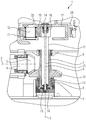
- a vertical mill is used for the comminution of different materials, such as brown and hard coal, limestone, minerals, cement or the like. It includes for this purpose a horizontal not shown in the drawing Grinding plate, which is rotationally driven via a motor, also not shown, and arranged between the motor and grinding plate, only partially shown in the drawing vertical mill gear 1. The crushing is done in a grinding bowl, press in the grinding tools against the grinding table.
- the main tasks of the vertical mill 1 consist in the power transmission, the translation of the required torque and the required speed, the storage of the grinding bowl and the recording of grinding forces. It comprises a housing 2 and a drive shaft 4, which is rotatably mounted in this housing essentially horizontally about a first axis of rotation 3 and projects outwardly out of the housing 2 in the present case and is driven by a coupled motor (not shown).
- a bevel pinion 5 is provided, which is non-rotatably connected to the drive shaft 4 in such a way that the drive shaft 4 and the bevel pinion 5 are joined by means of a known shaft-hub connection, or that the drive shaft 4 is designed with the bevel pinion 5 as a one-piece bevel pinion shaft.
- the vertical mill gear 1 further comprises an in the housing 2 rotatably mounted about a substantially vertical second axis of rotation 6 intermediate shaft 7, which is supported in the lower region via a radial-axial bearing 8 and in the upper region via at least one radial bearing 9 on the housing 2.
- the intermediate shaft 7 In the lower part of the intermediate shaft 7 rotatably carries a bevel gear 10, which is in engagement with the bevel pinion 5 and together with this forms a bevel gear. Accordingly, the intermediate shaft 7 is rotatably driven via the bevel gear. According to the invention, the intermediate shaft 7 is formed as a hollow shaft. Further, in the intermediate shaft 7 according to the invention a presently also designed as a hollow-drilled shaft torsion shaft 11 is arranged and rotatably connected to the intermediate shaft 7.
- the rotationally fixed connection between the intermediate shaft 7 and the torsion shaft 11 is in the present case via a positive and / or non-positive coupling teeth 12 realized in the lower region of the intermediate shaft 11.
- the coupling toothing 12 is arranged centrally in the point of action of the radial-axial bearing 8.
- the torsion shaft 11 is inserted from above with radial play in the intermediate shaft 7, is supported at the lower free end indirectly from the housing 2 and projects upwards from the intermediate shaft 7.
- the torsion shaft 11 is at the lower end of the front side on a provided with a central bore end plate 13 on the intermediate shaft 7.
- In the central bore sealing connecting pieces 14 are used, on the non-illustrated by the stationary housing 2 lubricating oil in the bore 15 of the torsion shaft 11 and from there from in the overhead lubrication points in the vertical mill gear 1 can be passed.
- a sun gear 16 of the vertical mill gear 1 is fixed. Shown is a one-piece component.
- planet carrier 17 is at least one rotatable about an associated Planetenrad loftachse 18 planetary gear 19 held on the one hand with the sun gear 16 and on the other hand with an internal toothing 20 of a stationary held on the housing 2 ring gear 21 meshes ,
- a plurality of planet gears 19 are held on the planet carrier 17 in a known manner, whereby the drive power branches in a known manner to the therefore relatively small-sized planetary gears 19.
- Second planetary stage is arranged in a known manner, which is rotatably connected via a further output coupling 22 with the sun gear of the second planetary stage, not shown, and then indirectly connected to the drive side rotatably on the drive side.
- the drive shaft 4 is driven in rotation by a motor.
- the rotational movement of the drive shaft 4 is transmitted via the cone stage (5, 10) with a predetermined transmission ratio to the intermediate shaft 7.
- the sun gear 16 in turn rotates the planet carrier 17 via the meshing with the sun gear 16 and the ring gear 21 planetary gears 19 and converts again in this gear stage with the intermediate shaft 7 rotatably inserted into this torsion shaft 11 at the same speed Speed and torque. Accordingly, the second planetary stage with the grinding table is driven in rotation via the planet carrier 17 via the drive clutch 22.
- a significant advantage of the construction of the vertical mill gear 1 according to the invention is that the sun gear 16 attached to the torsion shaft 11 can follow the radial displacement of the planet gear carrier 17 independently of the process loads without adversely affecting the bevel gear stage.
- the loads from the bevel gear can lead to an elastic deformation of the intermediate shaft 7, without affecting the planetary stage negative.
- the decoupling of the deformations and displacements from the process loads and the loads of the bevel gear 10 is achieved thanks to the torsion shaft 11 accommodating the sun gear 16 within the intermediate shaft 7 receiving the bevel gear 10.
- the central arrangement of the coupling gear 12 also contributes to this decoupling Radial thrust bearing 8 at.
- the torsion shaft 11 in addition, thanks to the suitably designed spring stiffness of the torsion shaft 11 and the natural frequencies of the drive train are laid in a non-critical non-resonant region and thus decoupled from the vibration excitation of the milling process, whereby a total of a long life of the vertical mill gear 2 of the invention is achieved.
- the individually determinable lengths of the torsion shaft 11 lead in addition to a very rotationally soft shaft similar to a torsion spring that absorbs shocks from the grinding process, so that they can only slightly act on the bevel gear.
Landscapes
- Engineering & Computer Science (AREA)
- General Engineering & Computer Science (AREA)
- Mechanical Engineering (AREA)
- Food Science & Technology (AREA)
- Crushing And Grinding (AREA)
- Retarders (AREA)
- Gear Transmission (AREA)
Description
- Die Erfindung betrifft ein Vertikalmühlengetriebe mit einem Gehäuse, einer in dem Gehäuse um eine im Wesentlichen horizontale erste Drehachse drehbar gelagerte Antriebswelle, die an einem ihrer Enden mit einem Kegelritzel versehen ist, einer in dem Gehäuse drehbar um eine im Wesentlichen vertikale zweite Drehachse gelagerte Zwischenwelle, die im unteren Bereich mit einem mit dem Kegelritzel im Eingriff stehenden Kegelrad versehen ist, einem über die Zwischenwelle drehend angetriebenen Sonnenrad einer ersten Planetenstufe und einem in dem Gehäuse drehbar um die zweite Drehachse gelagerten Planetenradträger, an dem drehbar um eine zugeordnete Planetenraddrehachse zumindest ein Planetenrad gehalten ist, das einerseits mit dem Sonnenrad und andererseits mit einer Innenverzahnung eines ortsfest an dem Gehäuse gehaltenen Hohlrads im Eingriff ist. Diese erste Planetenstufe in dem Vertikalmühlengetriebe kann vorteilhafterweise eine zweite abtreibseitige Planetenstufe, die ebenfalls um die vertikale zweite Drehachse rotiert und wiederum aus einer von der Vorstufe angetriebenen Sonnenrad, einem einstellbeweglichen zweiten Planetenträger und einem gehäusefesten zweiten Hohlrad aufgebaut ist, antreiben.
- Vertikalmühlengetriebe der eingangs genannten Art sind im Stand der Technik in unterschiedlichen Ausgestaltungen bekannt. Sie dienen nicht nur der Wandlung von Drehmomenten und Drehzahlen in Größe und Richtung, sondern auch der Aufnahme und Abstützung von Prozesslasten. Der Mahlprozess führt dabei zu Schwingungen, die Eigenfrequenzen des Triebstranges anregen, der durch einen Motor, eine Kupplung, die von diesen angetriebene Antriebswelle, das Kegelritzel, das Kegelrad, die Zwischenwelle, das an dieser gehaltene Sonnenrad, das zumindest eine Planetenrad, den Planetenradträger und das Hohlrad einer ersten Planetenstufe und einer vorteilhafterweise nachfolgenden zusätzlichen gleichartigen zweiten Planetenstufe oder weitere Planetenstufen gebildet wird. Derartige Eigenfrequenzen können den Antriebsstrang zumindest in Teilen oder vollständig zerstören. Üblicherweise ist das schwächste Element des Triebstranges am anfälligsten für Schäden. In Vertikalmühlengetrieben ist dies meist die durch das Kegelritzel und das Kegelrad gebildete Kegelradstufe. Ebenso ist bekannt, dass mit zusätzlichen einfach- oder doppelgelenkigen Kupplungen im Triebstrang zwischen Zwischenwelle und dem ersten Sonnenrad versucht wird, die einzelnen Stufen voneinander zu entkoppeln.
- Die Kegelradstufe dient dem Zweck der Wandlung des Drehmoments und der Drehzahl in Größe und Richtung. Das Drehmoment wird von dem Kegelritzel auf das Kegelrad übertragen. Dieses überträgt das Drehmoment auf die vertikal stehende Zwischenwelle. Hierbei führen die resultierenden Kräfte in der Verzahnung zu einer Verformung der Zwischenwelle, welche das Tragverhalten der Planetenvorstufe beeinflusst. Planetenstufen erfordern zum statisch bestimmten Aufbau zumindest ein frei einstellbares Glied, dass in dieser Form der Vertikalmühlengetriebe von dem Planetenträger dargestellt wird. Die ineinander abwälzenden verzahnten Räder können sich infolge des sich einstellenden Kräftegleichgewichts und der erzielten Fertigungstoleranzen frei einstellen und verschieben und damit den Planetenträger radial zur zweiten Drehachse innerhalb eines kleinen und zulässigen Bereichs. Zusätzlich führen diese Verschiebungen der Planetenvorstufe zu einer Beeinflussung des Tragverhaltens der Kegelradstufe. Untersuchungen haben zudem gezeigt, dass die Verformungen aus den Kräften der Kegelradstufe sich mit Verformungen und Verschiebungen anderer Elemente des Vertikalmühlengetriebes überlagern, die aus den Prozesslasten resultieren.
- Ein Problem besteht somit darin, dass die Prozesslasten aus dem Mahlvorgang, die Verschiebungen der einstellbeweglichen Glieder der Planetenstufen und die Verformung aus der Kegelradstufe das Tragverhalten der Verzahnung in der Planetenvorstufe und der Kegelradstufe negativ beeinflussen. Zudem ist die Kegelradstufe anfällig für durch die Prozesslasten verursachte Schwingungen und Stöße. In dem Triebstrang bauen sich somit interne Zusatzbeanspruchungen auf, die entweder zu Schäden führen oder eine Überdimensionierung erfordern
- Ausgehend von diesem Stand der Technik ist es eine Aufgabe der vorliegenden Erfindung, ein Vertikalmühlengetriebe der eingangs genannten Art mit alternativem Aufbau zu schaffen.
- Zur Lösung dieser Aufgabe schafft die vorliegende Erfindung ein Vertikalmühlengetriebe der eingangs genannten Art, das dadurch gekennzeichnet ist, dass die Zwischenwelle als Hohlwelle ausgebildet ist, und dass in der Zwischenwelle eine Torsionswelle angeordnet, form- bzw. kraftschlüssig im Sinne von drehfest und trotzdem winkeleinstellbeweglich mit dieser verbunden ist, dass die Anordnung dieser Anbindung der Torsionswelle an einem Punkt geringer Durchbiegung der Hohlwelle liegt, wobei die Torsionswelle aufwärts aus der Zwischenwelle vorsteht, und wobei an dem vorstehenden Abschnitt der Torsionswelle das Sonnenrad befestigt ist. Bevorzugt ist die Torsionswelle mit dem Sonnenrad einstückig ausgeführt.
- Im Gegensatz zum Stand der Technik ist das Kegelrad somit nicht auf einer üblicherweise als Vollwelle sondern auf einer als Hohlwelle ausgebildeten Zwischenwelle montiert, die in den Lagern biegesteif gelagert ist, und das Sonnenrad ist nicht mit der Zwischenwelle sondern an der in diese eingesetzte und drehfest mit dieser verbundene Torsionswelle angebracht. Die Vorteile des erfindungsgemäßen Vertikalmühlengetriebes führen damit dazu, dass die Verformungen und Verschiebungen aus den Prozesslasten und den Belastungen des Kegelrads voneinander entkoppelt werden. Darüber hinaus werden dank der drehweichen Torsionswelle auch Drehschwingungen aus dem Mahlprozess von der Kegelradstufe gedämpft, wodurch insgesamt eine lange Lebensdauer des erfindungsgemäßen Vertikalmühlengetriebes erzielt wird. Die Federsteifigkeit der Torsionswelle kann durch eine zweckmäßige Wahl der Parameter Länge, Durchmesser, Masse und Werkstoffeigenschaft so beeinflusst werden, dass sich die Eigenfrequenzen des Vertikalmühlengetriebes deutlich von den Erregerfrequenzen des Mahlprozesses unterscheiden. Auch verändert eine Bohrung durch die Torsionswelle entlang der Drehachse den Verformungswiderstand. Diese Bohrung lässt sich zudem zur Ölversorgung der obenliegenden Schmierstellen nutzen.
- Gemäß einer Ausgestaltung der vorliegenden Erfindung ist die Zwischenwelle im unteren Bereich mit einem Radial-Axial-Lager und im oberen Bereich über zumindest ein Radiallager in dem Gehäuse gelagert. Auf diese Weise werden die Kräfte und Verformungen aus der Kegelradstufe im Gehäuse abgestützt und nicht in die Verzahnung der Vorstufe bzw. in die nachfolgenden Stufen des Triebstranges gelegt.
- Der Abstand zwischen dem Radial-Axial-Lager und dem Radiallager kann möglichst klein ausgeführt sein, wobei die Zwischenwelle von diesen Lagern biegesteif abgeleitet ist. Dies führt zu einer biegesteifen Bauform der Zwischenwelle mit dem Vorteil einer geringeren Beeinträchtigung des Tragbilds der Kegelradstufe. In den Lagern der Zwischenwelle ist die Durchbiegung der Hohlwelle am geringsten und die verbliebende Auslenkung wird nur durch die geringe Lagerluft oder die Schmierspalthöhe bestimmt. Diese Stellen in der Hohlwelle eignen sich besonders zur Ankopplung der Torsionswelle.
- Bevorzugt ist die Torsionswelle von oben in die Zwischenwelle eingesteckt und über eine formschlüssige Verbindung, insbesondere in Form einer balligen Kupplungs- oder Kurzverzahnung, mit der Zwischenwelle verbunden, wodurch ein einfacher Aufbau erzielt wird. Die Kupplungsverzahnung ist insbesondere im unteren Bereich der Torsionswelle und der Zwischenwelle vorgesehen, so dass die Torsionswelle nur in ihrem unteren Bereich an der Zwischenwelle fixiert ist. Entsprechend kann die Torsionswelle radiale Verschiebungen des Planetenträgers am oberen Ende der Welle durch elastische Biegung des langen schlanken Schaftes von der Zwischenwelle kompensieren. Da die Torsionswelle und die Zwischenwelle formschlüssig verbunden sind, drehen sie mit der gleichen Drehzahl. Dies ermöglicht eine einfache axiale Abstützung der Torsionswelle auf deren unterer Stirnseite auf dem gleich schnell drehenden Boden der Zwischenwelle.
- Vorteilhaft ist die Zwischenwelle aus einem Gusswerkstoff hergestellt. Alternativ können Zwischenwelle und Kegelrad als einstückiges Schmiedeteil gestaltet sein.
- Die Torsionswelle kann mit einer inneren Bohrung entlang der Drehachse versehen sein, um einerseits durch Änderung der Masse und des Widerstandsmoments die Steifigkeit anzupassen und andererseits durch die Drehachse Schmieröl zu obenliegenden Schmierstellen im Getriebe zu leiten. In die Bohrung führen stirnseitig sichtende Verbindungsstücke und stellen die Verbindung zur Ölversorgung her.
- Gemäß einer Ausgestaltung der vorliegenden Erfindung kann eine vergrößerte Länge der Torsionswelle zu einer Verringerung des Kippwinkels des Sonnenrads bei einer Verschiebung der Planetenräder führen. Darüber hinaus kann als weiterer Vorteil des erfindungsgemäßen Vertikalmühlengetriebes die Änderung der Länge der Torsionswelle besonders einfach dazu benutzt werden, um die Bauhöhe des gesamten Vertikalmühlengetriebes individuell Kundenspezifikationen der Vertikalmühle anzupassen.
- Weitere Merkmale und Vorteile der vorliegenden Erfindung werden anhand der nachfolgenden Beschreibung eines Vertikalmühlengetriebes gemäß einer Ausführungsform der vorliegenden Erfindung unter Bezugnahme auf die beiliegende Zeichnung deutlich, die eine schematische Teilschnittansicht des Vertikalmühlengetriebes zeigt.
- Eine Vertikalmühle dient zur Zerkleinerung unterschiedlicher Materialien, wie beispielsweise Braun- und Steinkohle, Kalkstein, Mineralien, Zementmaterial oder dergleichen. Sie umfasst hierzu einen in der Zeichnung nicht dargestellten horizontalen Mahlteller, der über einen ebenfalls nicht dargestellten Motor und ein zwischen Motor und Mahlteller angeordnetes, in der Zeichnung nur ausschnittsweise dargestelltes Vertikalmühlengetriebe 1 drehend angetrieben wird. Die Zerkleinerung erfolgt in einer Mahlschüssel, in der Mahlwerkzeuge gegen den Mahlteller drücken.
- Die Hauptaufgaben des Vertikalmühlengetriebes 1 bestehen in der Leistungsübertragung, der Übersetzung des erforderlichen Drehmomentes und der erforderlichen Drehzahl, der Lagerung der Mahlschüssel und der Aufnahme der Mahlkräfte. Es umfasst ein Gehäuse 2 und eine in diesem im Wesentlichen horizontal um eine erste Drehachse 3 drehbar gelagerte Antriebswelle 4, die im vorliegenden Fall auswärts aus dem Gehäuse 2 vorsteht und über einen nicht näher dargestellten angekuppelten Motor angetrieben wird. An dem innerhalb des Gehäuses 2 angeordneten freien Ende der Antriebswelle 4 ist ein Kegelritzel 5 vorgesehen, das drehfest mit der Antriebswelle 4 in der Art verbunden ist, dass die Antriebswelle 4 und das Kegelritzel 5 mittels einer bekannten Welle-Nabe-Verbindung gefügt sind, oder dass die Antriebswelle 4 mit dem Kegelritzel 5 als einstückige Kegelritzelwelle ausgeführt ist. Das Vertikalmühlengetriebe 1 umfasst ferner eine in dem Gehäuse 2 drehbar um eine im Wesentlichen vertikale zweite Drehachse 6 gelagerte Zwischenwelle 7, die sich im unteren Bereich über ein Radial-Axial-Lager 8 und im oberen Bereich über zumindest ein Radiallager 9 am Gehäuse 2 abstützt. Im unteren Bereich trägt die Zwischenwelle 7 drehfest ein Kegelrad 10, das mit dem Kegelritzel 5 in Eingriff steht und gemeinsam mit diesem eine Kegelradstufe bildet. Entsprechend ist die Zwischenwelle 7 über die Kegelradstufe drehend antreibbar. Erfindungsgemäß ist die Zwischenwelle 7 als Hohlwelle ausgebildet. Ferner ist in der Zwischenwelle 7 erfindungsgemäß eine vorliegend ebenfalls als hohlgebohrte Welle ausgebildete Torsionswelle 11 angeordnet und drehfest mit der Zwischenwelle 7 verbunden.
- Die drehfeste Verbindung zwischen der Zwischenwelle 7 und der Torsionswelle 11 ist vorliegend über eine form- und/oder kraftschlüssige Kupplungsverzahnung 12 im unteren Bereich der Zwischenwelle 11 realisiert. Die Kupplungsverzahnung 12 ist mittig im Wirkpunkt des Radial-Axial-Lagers 8 angeordnet.
- Die Torsionswelle 11 ist von oben mit radialem Spiel in die Zwischenwelle 7 eingesteckt, stützt sich am unteren freien Ende indirekt am Gehäuse 2 ab und steht aufwärts aus der Zwischenwelle 7 vor. Die Torsionswelle 11 steht am unteren Ende stirnseitig auf einer mit einer mittigen Bohrung versehenen Endscheibe 13 an der Zwischenwelle 7. In die mittige Bohrung sind dichtende Verbindungsstücke 14eingesetzt, über die vom stillstehenden Gehäuse 2 nicht dargestelltes Schmieröl in die Bohrung 15 der Torsionswelle 11 und von dort aus in den obenliegenden Schmierstellen im Vertikalmühlengetriebe 1 geleitet werden kann. An dem aus der Zwischenwelle 7 vorstehenden Abschnitt der Torsionswelle 11 ist ein Sonnenrad 16 des Vertikalmühlengetriebes 1 befestigt. Dargestellt ist ein einstückiges Bauteil. An einem in dem Gehäuse 2 drehbar um die zweite Drehachse 6 gelagerten Planetenradträger 17 ist zumindest ein um eine zugeordnete Planetenraddrehachse 18 drehbares Planetenrad 19 gehalten, das einerseits mit dem Sonnenrad 16 und andererseits mit einer Innenverzahnung 20 eines ortsfest an dem Gehäuse 2 gehaltenen Hohlrads 21 kämmt. Bevorzugt sind in bekannter Weise mehrere Planetenräder 19 an dem Planetenradträger 17 gehalten, wodurch sich die Antriebsleistung in bekannter Weise auf die deshalb relativ kleinbauenden Planetenräder 19 verzweigt. An der Oberseite des Planetenradträgers 17 ist in bekannter Weise eine vorliegend nicht näher dargestellte zweite Planetenstufe angeordnet, die über eine weitere Abtriebskupplung 22 mit dem nicht dargestellten Sonnenrad der zweiten Planetenstufe drehfest verbunden ist, und dann mittelbar an der Antriebsseite mit dem Mahlteller drehfest verbunden ist.
- Während des Betriebs wird die Antriebswelle 4 über einen Motor drehend angetrieben. Die Drehbewegung der Antriebswelle 4 wird über die Kegelstufe (5, 10) mit einem vorbestimmten Übersetzungsverhältnis auf die Zwischenwelle 7 übertragen.
- Mit der Zwischenwelle 7 dreht sich die drehfest in diese eingesetzte Torsionswelle 11 mit der gleichen Drehzahl und damit das Sonnenrad 16. Das Sonnenrad 16 dreht wiederum den Planetenradträger 17 über die mit dem Sonnenrad 16 und dem Hohlrad 21 kämmenden Planetenräder 19 und wandelt in dieser Getriebestufe wiederum Drehzahl und Drehmoment. Entsprechend wird die zweite Planetenstufe mit dem Mahlteller drehend über den Planetenradträger 17 über die Antriebskupplung 22 angetrieben.
- Ein wesentlicher Vorteil des Aufbaus des erfindungsgemäßen Vertikalmühlengetriebes 1 besteht darin, dass das an der Torsionswelle 11 befestigte Sonnenrad 16 der radialen Verschiebung des Planetenradträgers 17 aus den Prozesslasten unabhängig folgen kann, ohne die Kegelradstufe negativ zu beeinflussen. In umgekehrter Richtung können die Belastungen aus der Kegelradstufe zu einer elastischen Verformung der Zwischenwelle 7 führen, ohne die Planetenstufe negativ zu beeinflussen. Bewerkstelligt wird die Entkopplung der Verformungen und Verschiebungen aus den Prozesslasten und den Belastungen des Kegelrads 10 dank der innerhalb der das Kegelrad 10 aufnehmenden Zwischenwelle 7 angeordneten, das Sonnenrad 16 aufnehmenden Torsionswelle 11. Zu dieser Entkopplung trägt auch die mittige Anordnung der Kupplungsverzahnung 12 im Wirkpunkt des Radial-Axial-Lagers 8 bei. Darüber hinaus werden dank der zweckmäßig ausgelegten Federsteifigkeit der Torsionswelle 11 auch die Eigenfrequenzen des Triebstrangs in einen unkritischen nicht resonanzgefährdeten Bereich verlegt und so von der Schwingungserregung aus dem Mahlprozess entkoppelt, wodurch insgesamt eine lange Lebensdauer des erfindungsgemäßen Vertikalmühlengetriebes 2 erzielt wird. Die individuell bestimmbaren Längen der Torsionswelle 11 führen zusätzlich zu einer sehr drehweichen Welle ähnlich einer Drehfeder, die Stöße aus dem Mahlprozess dämpft, so dass diese nur geringfügig auf die Kegelradstufe einwirken können.
- Obwohl die Erfindung im Detail durch das bevorzugte Ausführungsbeispiel näher illustriert und beschrieben wurde, so ist die Erfindung nicht durch die offenbarten Beispiele eingeschränkt und andere Variationen können vom Fachmann hieraus abgeleitet werden, ohne den Schutzumfang der Erfindung zu verlassen.
Claims (13)
- Vertikalmühlengetriebe (1) mit einem Gehäuse (2), einer in dem Gehäuse (2) um eine im Wesentlichen horizontale erste Drehachse (3) drehbar gelagerte Antriebswelle (4), die an einem ihrer Enden mit einem Kegelritzel (5) versehen ist, einer in dem Gehäuse (2) drehbar um eine im Wesentlichen vertikale zweite Drehachse (6) gelagerte Zwischenwelle (7), die im unteren Bereich mit einem mit dem Kegelritzel (5) im Eingriff stehenden Kegelrad (10) versehen ist, einem über die Zwischenwelle (7) drehend angetriebenen Sonnenrad (16) und einem in dem Gehäuse (2) drehbar um die zweite Drehachse (6) gelagerten ersten Planetenradträger (17), an dem drehbar um eine zugeordnete Planetenraddrehachse (18) zumindest ein Planetenrad (19) gehalten ist, das einerseits mit dem Sonnenrad (16) und andererseits mit einer Innenverzahnung (20) eines ortsfest an dem Gehäuse (2) gehaltenen Hohlrads (21) im Eingriff ist, dadurch gekennzeichnet, dass die Zwischenwelle (7) als Hohlwelle ausgebildet ist, und dass in die Zwischenwelle (7) eine Torsionswelle (11) eingesteckt, drehfest und winkeleinstellbeweglich mit dieser verbunden ist, wobei die Torsionswelle (11) aufwärts aus der Zwischenwelle (7) vorsteht, und wobei an dem vorstehenden Abschnitt der Torsionswelle (11) das Sonnenrad (16) befestigt ist.
- Vertikalmühlengetriebe (1) nach Anspruch 1, dadurch gekennzeichnet, dass die Zwischenwelle (7) im unteren Bereich mit einem Radial-Axial-Lager (8) und im oberen Bereich über zumindest ein Radiallager (9) in dem Gehäuse (2) gelagert ist.
- Vertikalmühlengetriebe (1) nach Anspruch 2, dadurch gekennzeichnet, dass der Abstand zwischen dem Radial-Axial-Lager (8) und dem Radiallager (9) möglichst klein ausgeführt ist und dass die Zwischenwelle (7) von diesen Lagern biegesteif abgestützt ist.
- Vertikalmühlengetriebe (1) nach einem der vorhergehenden Ansprüche, dadurch gekennzeichnet, dass die Torsionswelle (11) von oben in die Zwischenwelle (7) eingesteckt und über eine formschlüssige Verbindung, insbesondere in Form einer Kupplungsverzahnung (12) mit der Zwischenwelle (7) verbunden, wobei die Kupplungsverzahnung (12) insbesondere im unteren Bereich der Torsionswelle (11) und der Zwischenwelle (7) vorgesehen ist.
- Vertikalmühlengetriebe (1) nach einem der vorhergehenden Ansprüche, dadurch gekennzeichnet, dass die Kupplungsverzahnung (12) als form- oder kraftschlüssige Verbindung mittels einer balligen Kupplungs- oder Kurzverzahnung hergestellt ist.
- Vertikalmühlengetriebe (1) nach einem der vorhergehenden Ansprüche, dadurch gekennzeichnet, dass die Kupplungsverzahnung (12) in der Zwischenwelle (7) an einem Punkt geringer Durchbiegung liegt und dass das Radial-Axial-Lager (8) außen auf der Zwischenwelle (7) die innenliegende Kupplungsverzahnung (12) umschließt.
- Vertikalmühlengetriebe (1) nach einem der vorhergehenden Ansprüche, dadurch gekennzeichnet, dass die Länge der Torsionswelle (11) bestimmend für die Bauhöhe des gesamten Vertikalmühlengetriebes (1).
- Vertikalmühlengetriebe (1) nach einem der vorhergehenden Ansprüche, dadurch gekennzeichnet, dass eine Länge der Torsionswelle (11) den Kippwinkel des Sonnenrades (16) zu den Planetenrädern (19) verringert.
- Vertikalmühlengetriebe (1) nach einem der vorhergehenden Ansprüche, dadurch gekennzeichnet, dass die Federsteifigkeit der Torsionswelle (11) zur Anpassung der Eigenfrequenz durch die zweckmäßige Wahl der Parameter Länge, Durchmesser, Masse und Werkstoff bestimmt wird und dass eine Bohrung (15) durch die Torsionswelle (11) entlang der zweiten Drehachse (6) die Federsteifigkeit zweckmäßig ändert.
- Vertikalmühlengetriebe (1) nach einem der vorhergehenden Ansprüche, dadurch gekennzeichnet, dass die Bohrung (15) in der Torsionswelle (11) zur Durchleitung von Schmieröl zu obenliegenden Schmierstellen im Vertikalmühlengetriebe (1) dient und dass in die Bohrung (15) stirnseitig eingebrachte dichtende Verbindungsstücke (14) den Anschluss an ein Ölleitungssystem herstellen.
- Vertikalmühlengetriebe (1) nach einem der vorhergehenden Ansprüche, dadurch gekennzeichnet, dass die Torsionswelle (11) und das daran befestigte Sonnenrad (16) einstückig ausgeführt sind.
- Vertikalmühlengetriebe (1) nach einem der vorhergehenden Ansprüche, dadurch gekennzeichnet, dass sich die Torsionswelle (11) axial stirnseitig unten auf der Endscheibe (13) der Zwischenwelle (7) abstützt.
- Vertikalmühlengetriebe (1) nach einem der vorhergehenden Ansprüche, dadurch gekennzeichnet, dass die Zwischenwelle (7) aus einem Gusswerkstoff oder als einstückiges Schmiedeteil hergestellt ist.
Priority Applications (4)
| Application Number | Priority Date | Filing Date | Title |
|---|---|---|---|
| EP17176001.0A EP3415238B1 (de) | 2017-06-14 | 2017-06-14 | Vertikalmühlengetriebe |
| ES17176001T ES2812207T3 (es) | 2017-06-14 | 2017-06-14 | Transmisión de molino vertical |
| CN201810460376.9A CN109083981B (zh) | 2017-06-14 | 2018-05-14 | 立式磨传动装置 |
| US16/007,252 US10677331B2 (en) | 2017-06-14 | 2018-06-13 | Vertical mill gearbox |
Applications Claiming Priority (1)
| Application Number | Priority Date | Filing Date | Title |
|---|---|---|---|
| EP17176001.0A EP3415238B1 (de) | 2017-06-14 | 2017-06-14 | Vertikalmühlengetriebe |
Publications (2)
| Publication Number | Publication Date |
|---|---|
| EP3415238A1 true EP3415238A1 (de) | 2018-12-19 |
| EP3415238B1 EP3415238B1 (de) | 2020-05-27 |
Family
ID=59091336
Family Applications (1)
| Application Number | Title | Priority Date | Filing Date |
|---|---|---|---|
| EP17176001.0A Active EP3415238B1 (de) | 2017-06-14 | 2017-06-14 | Vertikalmühlengetriebe |
Country Status (4)
| Country | Link |
|---|---|
| US (1) | US10677331B2 (de) |
| EP (1) | EP3415238B1 (de) |
| CN (1) | CN109083981B (de) |
| ES (1) | ES2812207T3 (de) |
Cited By (2)
| Publication number | Priority date | Publication date | Assignee | Title |
|---|---|---|---|---|
| CN116943831A (zh) * | 2023-09-19 | 2023-10-27 | 昆明众康制药有限公司 | 一种中药材粉碎研磨装置 |
| CN119689852A (zh) * | 2024-12-03 | 2025-03-25 | 重庆大学 | 立磨齿轮箱齿轮寿命在线智能调控方法及系统 |
Families Citing this family (5)
| Publication number | Priority date | Publication date | Assignee | Title |
|---|---|---|---|---|
| JP7051450B2 (ja) * | 2018-01-12 | 2022-04-11 | 三菱重工業株式会社 | 粉砕機及び粉砕機の製造方法 |
| EP3705747B1 (de) | 2019-03-04 | 2022-02-23 | IMS Gear SE & Co. KGaA | Stirnradgetriebe |
| DE102019130387B3 (de) | 2019-11-11 | 2020-09-10 | Gwf Messsysteme Ag | Zählwerk |
| EP3885597B1 (de) * | 2020-03-25 | 2024-07-10 | Flender GmbH | Kupplung und verfahren zum berührungslosen erfassen von verschleiss an der kupplung |
| CN112044533B (zh) * | 2020-08-14 | 2021-11-09 | 南京钜力智能制造技术研究院有限公司 | 一种智能立磨装置及其磨制方法 |
Citations (4)
| Publication number | Priority date | Publication date | Assignee | Title |
|---|---|---|---|---|
| DE2707699A1 (de) * | 1977-02-23 | 1978-08-24 | Thyssen Industrie | Getriebe mit veraenderbarer uebersetzung |
| GB2001553A (en) * | 1977-07-01 | 1979-02-07 | Kienast Gmbh Zahnradfab | A roller mill |
| CH694244A5 (de) * | 1999-04-19 | 2004-10-15 | Renk Ag | Getriebe für eine Schüsselmühle. |
| WO2016198146A1 (de) * | 2015-06-12 | 2016-12-15 | Sew-Eurodrive Gmbh & Co. Kg | Getriebe mit einem gehäuse und einer planetengetriebestufe |
Family Cites Families (13)
| Publication number | Priority date | Publication date | Assignee | Title |
|---|---|---|---|---|
| US3037429A (en) * | 1958-02-05 | 1962-06-05 | Giddings & Lewis | Right angle milling attachment |
| DE1929912C3 (de) * | 1969-06-12 | 1981-10-15 | Gebr. Pfeiffer Ag, 6750 Kaiserslautern | Walzenschüsselmühle mit umlaufender Mahlschüssel |
| US4210291A (en) * | 1978-07-10 | 1980-07-01 | Erste Osterreichische Zahnraderfabrick Rudolf Kienast Gesellschaft m.b.H. | Roller mill |
| DK1757839T3 (da) * | 2005-08-24 | 2008-07-21 | Maag Gear Ag | Gear til svær belastning til valsetallerkenmöller |
| CN2830786Y (zh) * | 2005-10-19 | 2006-10-25 | 重庆齿轮箱有限责任公司 | 立式锥-平行轴-行星三级传动减速机 |
| CN102186592B (zh) * | 2008-08-22 | 2014-12-03 | Fl史密斯公司 | 重型驱动装置及由其驱动的磨机 |
| EP2380666B1 (de) | 2010-04-19 | 2013-04-17 | Siemens Aktiengesellschaft | Mühlenantriebssystem |
| CN202023888U (zh) * | 2011-04-08 | 2011-11-02 | 南京金腾重载齿轮箱有限公司 | 行星传动式大功率立磨减速机 |
| EP2511010B1 (de) * | 2011-04-14 | 2013-07-31 | Siemens Aktiengesellschaft | Vertikalmühlengetriebe |
| DE102013213005B3 (de) | 2013-07-03 | 2014-10-23 | Siemens Aktiengesellschaft | Maschinenschnittstelle, Antrieb und Vetikalmühle |
| EP2942223A1 (de) | 2014-05-07 | 2015-11-11 | Siemens Aktiengesellschaft | Antriebsachsenanordnung |
| PL3056278T3 (pl) | 2015-02-10 | 2019-11-29 | Flender Gmbh | Układ przekładni do młyna pionowego |
| ES2824260T3 (es) | 2015-04-23 | 2021-05-11 | Flender Gmbh | Deflector de aire para una transmisión y transmisión con un deflector de aire |
-
2017
- 2017-06-14 ES ES17176001T patent/ES2812207T3/es active Active
- 2017-06-14 EP EP17176001.0A patent/EP3415238B1/de active Active
-
2018
- 2018-05-14 CN CN201810460376.9A patent/CN109083981B/zh active Active
- 2018-06-13 US US16/007,252 patent/US10677331B2/en active Active
Patent Citations (4)
| Publication number | Priority date | Publication date | Assignee | Title |
|---|---|---|---|---|
| DE2707699A1 (de) * | 1977-02-23 | 1978-08-24 | Thyssen Industrie | Getriebe mit veraenderbarer uebersetzung |
| GB2001553A (en) * | 1977-07-01 | 1979-02-07 | Kienast Gmbh Zahnradfab | A roller mill |
| CH694244A5 (de) * | 1999-04-19 | 2004-10-15 | Renk Ag | Getriebe für eine Schüsselmühle. |
| WO2016198146A1 (de) * | 2015-06-12 | 2016-12-15 | Sew-Eurodrive Gmbh & Co. Kg | Getriebe mit einem gehäuse und einer planetengetriebestufe |
Cited By (3)
| Publication number | Priority date | Publication date | Assignee | Title |
|---|---|---|---|---|
| CN116943831A (zh) * | 2023-09-19 | 2023-10-27 | 昆明众康制药有限公司 | 一种中药材粉碎研磨装置 |
| CN116943831B (zh) * | 2023-09-19 | 2023-11-28 | 昆明众康制药有限公司 | 一种中药材粉碎研磨装置 |
| CN119689852A (zh) * | 2024-12-03 | 2025-03-25 | 重庆大学 | 立磨齿轮箱齿轮寿命在线智能调控方法及系统 |
Also Published As
| Publication number | Publication date |
|---|---|
| US10677331B2 (en) | 2020-06-09 |
| CN109083981A (zh) | 2018-12-25 |
| EP3415238B1 (de) | 2020-05-27 |
| US20180363747A1 (en) | 2018-12-20 |
| CN109083981B (zh) | 2021-07-06 |
| ES2812207T3 (es) | 2021-03-16 |
Similar Documents
| Publication | Publication Date | Title |
|---|---|---|
| EP3415238B1 (de) | Vertikalmühlengetriebe | |
| EP1279867B1 (de) | Getriebe mit Leistungsaufteilung | |
| EP2499361B1 (de) | Windturbine | |
| EP1482210A2 (de) | Getriebe für den Antrieb eines Drehrohres | |
| WO2010043193A1 (de) | Antriebswellenanordnung für ein getriebe eines kraftfahrzeuges | |
| EP2356390B1 (de) | Vorrichtung zum übertragen eines drehmoments auf einen drehrohfen | |
| EP1318329A2 (de) | Getriebe für eine Windkraftanlage | |
| DE202004016178U1 (de) | Differentialachsenkreuz für ein Ausgleichsgetriebe | |
| EP2473761B1 (de) | Differenzial | |
| DE102004008538B4 (de) | Differential mit einer Bolzenbefestigungsbaugruppe | |
| CH694243A5 (de) | Getriebe für eine Schüsselmühle. | |
| CH412497A (de) | Stirnräder-Planetengetriebe | |
| EP1003671B1 (de) | Getriebe mit leistungsverzweigung, insbesondere für einen hubschrauber-rotor-antrieb | |
| EP2511010A1 (de) | Vertikalmühlengetriebe | |
| DE1209391B (de) | Umlaufraeder- oder Mehrweggetriebe mit Schraegverzahnung | |
| EP1756426B1 (de) | Pumpe | |
| DE3624268C2 (de) | ||
| DE102019205608B4 (de) | Parksperrenrad | |
| EP2302255A2 (de) | Antriebsvorrichtung für zumindest einen Nebentrieb | |
| DE102010004579A1 (de) | Ventiltrieb einer Brennkraftmaschine | |
| AT116305B (de) | Kegelradgetriebe. | |
| DE102019115283A1 (de) | Ein Differentialgetriebe und ein Fahrzeug mit einem Differentialgetriebe | |
| EP2980447A1 (de) | Exzentergetriebe oder Exzenterstufe und Antrieb mit Exzentergetriebe oder Exzenterstufe | |
| DE1915661A1 (de) | Drehvorrichtung fuer schwere Koerper,beispielsweise Zementmahlwerke,Zementoefen od.dgl.,um deren eigene Achse | |
| DE483745C (de) | Kegelraedergetriebe mit selbsttaetig sich einstellenden Hauptraedern und zwischen diesen angeordneten Planetenraedern, insbesondere fuer Flugmotoren |
Legal Events
| Date | Code | Title | Description |
|---|---|---|---|
| PUAI | Public reference made under article 153(3) epc to a published international application that has entered the european phase |
Free format text: ORIGINAL CODE: 0009012 |
|
| STAA | Information on the status of an ep patent application or granted ep patent |
Free format text: STATUS: THE APPLICATION HAS BEEN PUBLISHED |
|
| AK | Designated contracting states |
Kind code of ref document: A1 Designated state(s): AL AT BE BG CH CY CZ DE DK EE ES FI FR GB GR HR HU IE IS IT LI LT LU LV MC MK MT NL NO PL PT RO RS SE SI SK SM TR |
|
| AX | Request for extension of the european patent |
Extension state: BA ME |
|
| RAP1 | Party data changed (applicant data changed or rights of an application transferred) |
Owner name: FLENDER GMBH |
|
| STAA | Information on the status of an ep patent application or granted ep patent |
Free format text: STATUS: REQUEST FOR EXAMINATION WAS MADE |
|
| 17P | Request for examination filed |
Effective date: 20190618 |
|
| RBV | Designated contracting states (corrected) |
Designated state(s): AL AT BE BG CH CY CZ DE DK EE ES FI FR GB GR HR HU IE IS IT LI LT LU LV MC MK MT NL NO PL PT RO RS SE SI SK SM TR |
|
| GRAP | Despatch of communication of intention to grant a patent |
Free format text: ORIGINAL CODE: EPIDOSNIGR1 |
|
| STAA | Information on the status of an ep patent application or granted ep patent |
Free format text: STATUS: GRANT OF PATENT IS INTENDED |
|
| INTG | Intention to grant announced |
Effective date: 20200103 |
|
| GRAS | Grant fee paid |
Free format text: ORIGINAL CODE: EPIDOSNIGR3 |
|
| GRAA | (expected) grant |
Free format text: ORIGINAL CODE: 0009210 |
|
| STAA | Information on the status of an ep patent application or granted ep patent |
Free format text: STATUS: THE PATENT HAS BEEN GRANTED |
|
| AK | Designated contracting states |
Kind code of ref document: B1 Designated state(s): AL AT BE BG CH CY CZ DE DK EE ES FI FR GB GR HR HU IE IS IT LI LT LU LV MC MK MT NL NO PL PT RO RS SE SI SK SM TR |
|
| REG | Reference to a national code |
Ref country code: GB Ref legal event code: FG4D Free format text: NOT ENGLISH |
|
| REG | Reference to a national code |
Ref country code: CH Ref legal event code: EP |
|
| REG | Reference to a national code |
Ref country code: AT Ref legal event code: REF Ref document number: 1273990 Country of ref document: AT Kind code of ref document: T Effective date: 20200615 |
|
| REG | Reference to a national code |
Ref country code: DE Ref legal event code: R096 Ref document number: 502017005423 Country of ref document: DE |
|
| REG | Reference to a national code |
Ref country code: FI Ref legal event code: FGE |
|
| REG | Reference to a national code |
Ref country code: LT Ref legal event code: MG4D |
|
| PG25 | Lapsed in a contracting state [announced via postgrant information from national office to epo] |
Ref country code: LT Free format text: LAPSE BECAUSE OF FAILURE TO SUBMIT A TRANSLATION OF THE DESCRIPTION OR TO PAY THE FEE WITHIN THE PRESCRIBED TIME-LIMIT Effective date: 20200527 Ref country code: SE Free format text: LAPSE BECAUSE OF FAILURE TO SUBMIT A TRANSLATION OF THE DESCRIPTION OR TO PAY THE FEE WITHIN THE PRESCRIBED TIME-LIMIT Effective date: 20200527 Ref country code: IS Free format text: LAPSE BECAUSE OF FAILURE TO SUBMIT A TRANSLATION OF THE DESCRIPTION OR TO PAY THE FEE WITHIN THE PRESCRIBED TIME-LIMIT Effective date: 20200927 Ref country code: NO Free format text: LAPSE BECAUSE OF FAILURE TO SUBMIT A TRANSLATION OF THE DESCRIPTION OR TO PAY THE FEE WITHIN THE PRESCRIBED TIME-LIMIT Effective date: 20200827 Ref country code: GR Free format text: LAPSE BECAUSE OF FAILURE TO SUBMIT A TRANSLATION OF THE DESCRIPTION OR TO PAY THE FEE WITHIN THE PRESCRIBED TIME-LIMIT Effective date: 20200828 Ref country code: PT Free format text: LAPSE BECAUSE OF FAILURE TO SUBMIT A TRANSLATION OF THE DESCRIPTION OR TO PAY THE FEE WITHIN THE PRESCRIBED TIME-LIMIT Effective date: 20200928 |
|
| REG | Reference to a national code |
Ref country code: NL Ref legal event code: MP Effective date: 20200527 |
|
| PG25 | Lapsed in a contracting state [announced via postgrant information from national office to epo] |
Ref country code: HR Free format text: LAPSE BECAUSE OF FAILURE TO SUBMIT A TRANSLATION OF THE DESCRIPTION OR TO PAY THE FEE WITHIN THE PRESCRIBED TIME-LIMIT Effective date: 20200527 Ref country code: RS Free format text: LAPSE BECAUSE OF FAILURE TO SUBMIT A TRANSLATION OF THE DESCRIPTION OR TO PAY THE FEE WITHIN THE PRESCRIBED TIME-LIMIT Effective date: 20200527 Ref country code: LV Free format text: LAPSE BECAUSE OF FAILURE TO SUBMIT A TRANSLATION OF THE DESCRIPTION OR TO PAY THE FEE WITHIN THE PRESCRIBED TIME-LIMIT Effective date: 20200527 Ref country code: BG Free format text: LAPSE BECAUSE OF FAILURE TO SUBMIT A TRANSLATION OF THE DESCRIPTION OR TO PAY THE FEE WITHIN THE PRESCRIBED TIME-LIMIT Effective date: 20200827 |
|
| PG25 | Lapsed in a contracting state [announced via postgrant information from national office to epo] |
Ref country code: AL Free format text: LAPSE BECAUSE OF FAILURE TO SUBMIT A TRANSLATION OF THE DESCRIPTION OR TO PAY THE FEE WITHIN THE PRESCRIBED TIME-LIMIT Effective date: 20200527 Ref country code: NL Free format text: LAPSE BECAUSE OF FAILURE TO SUBMIT A TRANSLATION OF THE DESCRIPTION OR TO PAY THE FEE WITHIN THE PRESCRIBED TIME-LIMIT Effective date: 20200527 |
|
| PG25 | Lapsed in a contracting state [announced via postgrant information from national office to epo] |
Ref country code: SM Free format text: LAPSE BECAUSE OF FAILURE TO SUBMIT A TRANSLATION OF THE DESCRIPTION OR TO PAY THE FEE WITHIN THE PRESCRIBED TIME-LIMIT Effective date: 20200527 Ref country code: EE Free format text: LAPSE BECAUSE OF FAILURE TO SUBMIT A TRANSLATION OF THE DESCRIPTION OR TO PAY THE FEE WITHIN THE PRESCRIBED TIME-LIMIT Effective date: 20200527 Ref country code: DK Free format text: LAPSE BECAUSE OF FAILURE TO SUBMIT A TRANSLATION OF THE DESCRIPTION OR TO PAY THE FEE WITHIN THE PRESCRIBED TIME-LIMIT Effective date: 20200527 Ref country code: RO Free format text: LAPSE BECAUSE OF FAILURE TO SUBMIT A TRANSLATION OF THE DESCRIPTION OR TO PAY THE FEE WITHIN THE PRESCRIBED TIME-LIMIT Effective date: 20200527 Ref country code: CZ Free format text: LAPSE BECAUSE OF FAILURE TO SUBMIT A TRANSLATION OF THE DESCRIPTION OR TO PAY THE FEE WITHIN THE PRESCRIBED TIME-LIMIT Effective date: 20200527 |
|
| REG | Reference to a national code |
Ref country code: CH Ref legal event code: PL |
|
| PG25 | Lapsed in a contracting state [announced via postgrant information from national office to epo] |
Ref country code: PL Free format text: LAPSE BECAUSE OF FAILURE TO SUBMIT A TRANSLATION OF THE DESCRIPTION OR TO PAY THE FEE WITHIN THE PRESCRIBED TIME-LIMIT Effective date: 20200527 Ref country code: SK Free format text: LAPSE BECAUSE OF FAILURE TO SUBMIT A TRANSLATION OF THE DESCRIPTION OR TO PAY THE FEE WITHIN THE PRESCRIBED TIME-LIMIT Effective date: 20200527 Ref country code: MC Free format text: LAPSE BECAUSE OF FAILURE TO SUBMIT A TRANSLATION OF THE DESCRIPTION OR TO PAY THE FEE WITHIN THE PRESCRIBED TIME-LIMIT Effective date: 20200527 |
|
| REG | Reference to a national code |
Ref country code: DE Ref legal event code: R097 Ref document number: 502017005423 Country of ref document: DE |
|
| REG | Reference to a national code |
Ref country code: ES Ref legal event code: FG2A Ref document number: 2812207 Country of ref document: ES Kind code of ref document: T3 Effective date: 20210316 |
|
| PG25 | Lapsed in a contracting state [announced via postgrant information from national office to epo] |
Ref country code: LU Free format text: LAPSE BECAUSE OF NON-PAYMENT OF DUE FEES Effective date: 20200614 |
|
| PLBE | No opposition filed within time limit |
Free format text: ORIGINAL CODE: 0009261 |
|
| STAA | Information on the status of an ep patent application or granted ep patent |
Free format text: STATUS: NO OPPOSITION FILED WITHIN TIME LIMIT |
|
| PG25 | Lapsed in a contracting state [announced via postgrant information from national office to epo] |
Ref country code: LI Free format text: LAPSE BECAUSE OF NON-PAYMENT OF DUE FEES Effective date: 20200630 Ref country code: CH Free format text: LAPSE BECAUSE OF NON-PAYMENT OF DUE FEES Effective date: 20200630 Ref country code: IE Free format text: LAPSE BECAUSE OF NON-PAYMENT OF DUE FEES Effective date: 20200614 |
|
| 26N | No opposition filed |
Effective date: 20210302 |
|
| REG | Reference to a national code |
Ref country code: DE Ref legal event code: R082 Ref document number: 502017005423 Country of ref document: DE Representative=s name: MICHALSKI HUETTERMANN & PARTNER PATENTANWAELTE, DE |
|
| PG25 | Lapsed in a contracting state [announced via postgrant information from national office to epo] |
Ref country code: SI Free format text: LAPSE BECAUSE OF FAILURE TO SUBMIT A TRANSLATION OF THE DESCRIPTION OR TO PAY THE FEE WITHIN THE PRESCRIBED TIME-LIMIT Effective date: 20200527 |
|
| PG25 | Lapsed in a contracting state [announced via postgrant information from national office to epo] |
Ref country code: TR Free format text: LAPSE BECAUSE OF FAILURE TO SUBMIT A TRANSLATION OF THE DESCRIPTION OR TO PAY THE FEE WITHIN THE PRESCRIBED TIME-LIMIT Effective date: 20200527 Ref country code: MT Free format text: LAPSE BECAUSE OF FAILURE TO SUBMIT A TRANSLATION OF THE DESCRIPTION OR TO PAY THE FEE WITHIN THE PRESCRIBED TIME-LIMIT Effective date: 20200527 Ref country code: CY Free format text: LAPSE BECAUSE OF FAILURE TO SUBMIT A TRANSLATION OF THE DESCRIPTION OR TO PAY THE FEE WITHIN THE PRESCRIBED TIME-LIMIT Effective date: 20200527 |
|
| PG25 | Lapsed in a contracting state [announced via postgrant information from national office to epo] |
Ref country code: MK Free format text: LAPSE BECAUSE OF FAILURE TO SUBMIT A TRANSLATION OF THE DESCRIPTION OR TO PAY THE FEE WITHIN THE PRESCRIBED TIME-LIMIT Effective date: 20200527 |
|
| REG | Reference to a national code |
Ref country code: AT Ref legal event code: MM01 Ref document number: 1273990 Country of ref document: AT Kind code of ref document: T Effective date: 20220614 |
|
| PG25 | Lapsed in a contracting state [announced via postgrant information from national office to epo] |
Ref country code: AT Free format text: LAPSE BECAUSE OF NON-PAYMENT OF DUE FEES Effective date: 20220614 |
|
| PGFP | Annual fee paid to national office [announced via postgrant information from national office to epo] |
Ref country code: FI Payment date: 20250627 Year of fee payment: 9 |
|
| PGFP | Annual fee paid to national office [announced via postgrant information from national office to epo] |
Ref country code: DE Payment date: 20250625 Year of fee payment: 9 |
|
| PGFP | Annual fee paid to national office [announced via postgrant information from national office to epo] |
Ref country code: GB Payment date: 20250618 Year of fee payment: 9 |
|
| PGFP | Annual fee paid to national office [announced via postgrant information from national office to epo] |
Ref country code: BE Payment date: 20250618 Year of fee payment: 9 |
|
| PGFP | Annual fee paid to national office [announced via postgrant information from national office to epo] |
Ref country code: FR Payment date: 20250625 Year of fee payment: 9 |
|
| PGFP | Annual fee paid to national office [announced via postgrant information from national office to epo] |
Ref country code: ES Payment date: 20250728 Year of fee payment: 9 |
|
| PGFP | Annual fee paid to national office [announced via postgrant information from national office to epo] |
Ref country code: IT Payment date: 20250624 Year of fee payment: 9 |