EP3414508B1 - Kreuzstromplattenwärme- und/oder -feuchteaustauscher - Google Patents
Kreuzstromplattenwärme- und/oder -feuchteaustauscher Download PDFInfo
- Publication number
- EP3414508B1 EP3414508B1 EP16707626.4A EP16707626A EP3414508B1 EP 3414508 B1 EP3414508 B1 EP 3414508B1 EP 16707626 A EP16707626 A EP 16707626A EP 3414508 B1 EP3414508 B1 EP 3414508B1
- Authority
- EP
- European Patent Office
- Prior art keywords
- flow
- cross
- plates
- moisture exchanger
- plate heat
- Prior art date
- Legal status (The legal status is an assumption and is not a legal conclusion. Google has not performed a legal analysis and makes no representation as to the accuracy of the status listed.)
- Active
Links
Images
Classifications
-
- F—MECHANICAL ENGINEERING; LIGHTING; HEATING; WEAPONS; BLASTING
- F28—HEAT EXCHANGE IN GENERAL
- F28D—HEAT-EXCHANGE APPARATUS, NOT PROVIDED FOR IN ANOTHER SUBCLASS, IN WHICH THE HEAT-EXCHANGE MEDIA DO NOT COME INTO DIRECT CONTACT
- F28D9/00—Heat-exchange apparatus having stationary plate-like or laminated conduit assemblies for both heat-exchange media, the media being in contact with different sides of a conduit wall
- F28D9/0062—Heat-exchange apparatus having stationary plate-like or laminated conduit assemblies for both heat-exchange media, the media being in contact with different sides of a conduit wall the conduits for one heat-exchange medium being formed by spaced plates with inserted elements
- F28D9/0068—Heat-exchange apparatus having stationary plate-like or laminated conduit assemblies for both heat-exchange media, the media being in contact with different sides of a conduit wall the conduits for one heat-exchange medium being formed by spaced plates with inserted elements with means for changing flow direction of one heat exchange medium, e.g. using deflecting zones
-
- F—MECHANICAL ENGINEERING; LIGHTING; HEATING; WEAPONS; BLASTING
- F28—HEAT EXCHANGE IN GENERAL
- F28D—HEAT-EXCHANGE APPARATUS, NOT PROVIDED FOR IN ANOTHER SUBCLASS, IN WHICH THE HEAT-EXCHANGE MEDIA DO NOT COME INTO DIRECT CONTACT
- F28D21/00—Heat-exchange apparatus not covered by any of the groups F28D1/00 - F28D20/00
- F28D21/0001—Recuperative heat exchangers
- F28D21/0014—Recuperative heat exchangers the heat being recuperated from waste air or from vapors
-
- F—MECHANICAL ENGINEERING; LIGHTING; HEATING; WEAPONS; BLASTING
- F28—HEAT EXCHANGE IN GENERAL
- F28D—HEAT-EXCHANGE APPARATUS, NOT PROVIDED FOR IN ANOTHER SUBCLASS, IN WHICH THE HEAT-EXCHANGE MEDIA DO NOT COME INTO DIRECT CONTACT
- F28D21/00—Heat-exchange apparatus not covered by any of the groups F28D1/00 - F28D20/00
- F28D21/0015—Heat and mass exchangers, e.g. with permeable walls
-
- F—MECHANICAL ENGINEERING; LIGHTING; HEATING; WEAPONS; BLASTING
- F28—HEAT EXCHANGE IN GENERAL
- F28D—HEAT-EXCHANGE APPARATUS, NOT PROVIDED FOR IN ANOTHER SUBCLASS, IN WHICH THE HEAT-EXCHANGE MEDIA DO NOT COME INTO DIRECT CONTACT
- F28D9/00—Heat-exchange apparatus having stationary plate-like or laminated conduit assemblies for both heat-exchange media, the media being in contact with different sides of a conduit wall
- F28D9/0031—Heat-exchange apparatus having stationary plate-like or laminated conduit assemblies for both heat-exchange media, the media being in contact with different sides of a conduit wall the conduits for one heat-exchange medium being formed by paired plates touching each other
- F28D9/0043—Heat-exchange apparatus having stationary plate-like or laminated conduit assemblies for both heat-exchange media, the media being in contact with different sides of a conduit wall the conduits for one heat-exchange medium being formed by paired plates touching each other the plates having openings therein for circulation of at least one heat-exchange medium from one conduit to another
- F28D9/005—Heat-exchange apparatus having stationary plate-like or laminated conduit assemblies for both heat-exchange media, the media being in contact with different sides of a conduit wall the conduits for one heat-exchange medium being formed by paired plates touching each other the plates having openings therein for circulation of at least one heat-exchange medium from one conduit to another the plates having openings therein for both heat-exchange media
-
- F—MECHANICAL ENGINEERING; LIGHTING; HEATING; WEAPONS; BLASTING
- F28—HEAT EXCHANGE IN GENERAL
- F28D—HEAT-EXCHANGE APPARATUS, NOT PROVIDED FOR IN ANOTHER SUBCLASS, IN WHICH THE HEAT-EXCHANGE MEDIA DO NOT COME INTO DIRECT CONTACT
- F28D9/00—Heat-exchange apparatus having stationary plate-like or laminated conduit assemblies for both heat-exchange media, the media being in contact with different sides of a conduit wall
- F28D9/02—Heat-exchange apparatus having stationary plate-like or laminated conduit assemblies for both heat-exchange media, the media being in contact with different sides of a conduit wall the heat-exchange media travelling at an angle to one another
-
- F—MECHANICAL ENGINEERING; LIGHTING; HEATING; WEAPONS; BLASTING
- F28—HEAT EXCHANGE IN GENERAL
- F28F—DETAILS OF HEAT-EXCHANGE AND HEAT-TRANSFER APPARATUS, OF GENERAL APPLICATION
- F28F2250/00—Arrangements for modifying the flow of the heat exchange media, e.g. flow guiding means; Particular flow patterns
- F28F2250/10—Particular pattern of flow of the heat exchange media
- F28F2250/108—Particular pattern of flow of the heat exchange media with combined cross flow and parallel flow
Definitions
- the invention relates to a cross-flow plate heat and / or moisture exchanger whose plates are arranged above, below or next to each other and form flow passages alternately for a first and a second fluid.
- the present invention seeks to provide an improved cross-flow plate heat and / or moisture exchanger available, on the one hand has a better transmission performance in the transmission of heat and / or moisture between the two fluids and the In addition, compared to differential pressures between the two fluid streams is more pressure stable.
- the first cross-flow area of each plate causes a uniform distribution of the respective fluid flow to the counterflow region of each plate. Due to the different design of the adjacent plates, these can very well be supported against each other, yet in the region of the respective countercurrent areas an approximately parallel course of the respective flow channels is made possible.
- the counterflow passages of the counterflow region of each plate to the counterflow passages of the counterflow region of each adjacent Plate slightly, preferably by 5 degrees to 25 degrees, inclined.
- turbulence can be caused in the flows of the two fluids, which can contribute to an improvement in the transfer ratios of heat and / or moisture through the plates between the two fluids.
- the plates are rectangular or square.
- the counterflow regions of each plate are approximately oval or elliptical and extend between two opposite corners of the plate.
- the general flow direction A, B of the two fluids separated by the plates is selected by the cross-flow plate heat and / or moisture exchanger so that the two fluids flow through the counterflow regions of the cross-flow plate heat exchanger. and / or -feuchte tools in the opposite direction, ie about anti-parallel, flow through.
- each membrane plate has a membrane layer and a carrier layer. Enthalpy can be transferred between the two fluids by means of the membrane layer.
- the at least one carrier layer is designed openwork. By means of this openwork carrier layer The membrane plate are given a predetermined mechanical strength and a spatial structure, with both the mechanical strength and the spatial structure can be maintained over time.
- the membrane layer of the plates is expediently formed from a suitable plastic material, preferably a polyurethane or a polymer material.
- the carrier layer of the plates is expediently made of a suitable nonwoven material, preferably of a polyester material.
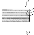
- FIG. 3 shown in a schematic representation according to the invention funnelstromplatten administrat- and / or -feuchtetooler 1 consists of a plate package, which is composed of plates 2, 3 different design or configuration.
- the plates 2 and the plates 3 are arranged alternately, that is, on a plate 2 of the first type is followed in each case by a plate 3 of the second type. Accordingly, each plate 2 of the first type has two adjacent plates 3 of the second type and vice versa.
- the plates 2, 3 are arranged one above the other. Of course, it is possible to arrange the plates 2, 3 also next to each other.
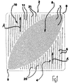
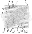
- the two mutually facing sides of the plates 2, 3 define flow passages for a first fluid, the cross-flow plate heat and / or moisture exchanger 1 in a in FIG. 1 flows through a direction indicated by arrows A, and for a second fluid which flows through the cross-flow plate heat and / or moisture exchanger 1 in a direction indicated in Figure 2 by arrows B general direction.
- the general direction A of the first fluid is arranged approximately perpendicular to the general direction B of the second fluid.
- the flow passages for the first fluid and for the second fluid are in the in FIG. 3 plate pack shown from the plates 2, 3 arranged alternately.
- the flow passages for the first fluid are defined by the in FIG. 1 shown embodiment of the plate 2 of the first Design determined.
- the flow passages for the second fluid are defined by the in FIG. 2 determined plate 3 of the second type determined.
- the plates 2, 3 of the cross-flow plate heat and / or moisture exchanger 1 may be made of any suitable material, e.g. made of aluminum or a PET plastic.
- the plates 2, 3 of the cross-flow plate heat and / or moisture exchanger 1 are designed as membrane plates.
- the respective membrane plates consist of a membrane layer, by means of which enthalpy is transferable between the two fluids, and at least one perforated support layer, by means of which the membrane plate a predetermined mechanical strength and a spatial structure rental and these are upright preserved.
- the membrane layer of the plates 2, 3 is then formed of a suitable plastic material, in particular a polyurethane or a polymer material.
- the carrier layer of the plates 2, 3 is then made of a suitable nonwoven material, preferably of a polyester fleece or the like., Is formed.
- the flow passages provided in the cross-flow plate heat and / or moisture exchanger 1 for the first fluid are described below with reference to FIGS FIG. 1 illustrated Structure of the plate 2 of the first type designed.
- the plate 2 has in the case of in FIG. 1 embodiment shown, a first cross-flow area 4, in which the first fluid enters.
- the first cross-flow region 4 has parallel flow channels 5, through which the first fluid is passed to a counter flow region 6 following the first cross flow region 4.
- the counterflow region 6 has a larger number of counterflow channels 7 in comparison to that of the flow channels 5 of the first cross flow region 4.
- the counterflow channels 7 are arranged inclined to the flow channels 5.
- the counterflow channels 7 at a certain length on lengths of different directions.
- the different length of the counterflow channels 7 results from the fact that the counterflow region 6 of the first plate 2 of their in FIG. 1 right upper corner 8 to their in FIG. 1 Left lower corner 9 extends and has a tapered in the direction of the two corners 8, 9 elliptical or oval shape.
- the first fluid is guided to a second crossflow region 10 of the plate 2.
- the second cross-flow area 10 has flow channels 11 which run parallel to the flow channels 5 of the first cross-flow area 4 and extend correspondingly in the general direction A, in which the first fluid flows through the cross-flow plate heat and / or moisture exchanger 1.
- the flow passages provided in the cross-flow plate heat and / or moisture exchanger 1 for the second fluid are, by the following on the basis of the FIG. 2 illustrated structure of the plate 3 of the second type designed.
- the plate 3 has in the case of in FIG. 2 embodiment shown, a first cross-flow region 12, in which the second fluid enters.
- the first cross-flow region 12 has parallel flow channels 13, through which the second fluid is passed to a counter flow region 14 following the first cross flow region 12.
- the countercurrent region 14 has a greater number of countercurrent channels 15 in comparison to that of the flow channels 13 of the first crossflow region 12.
- the counterflow channels 15 are arranged inclined to the flow channels 13.
- the counterflow channels 15 have lengths of different directions from a certain length.
- the different length of the counterflow channels 15 results from the fact that the counterflow region 14 of the second plate 3 of their in FIG. 2 right upper corner 16 to their in FIG. 2 left lower corner 17 extends and has in the direction of the two corners 16, 17 tapered elliptical or oval shape.
- the second cross-flow region 18 has flow channels 19 which run parallel to the flow channels 13 of the first cross-flow region 12 and extend correspondingly in the general direction B, in which the second fluid flows through the cross-flow plate heat and / or moisture exchanger 1.
- FIG. 1 and FIG. 2 shown plates 2, 3 of different types arranged alternately one above the other.
- FIG. 1 and FIG. 2 It can be seen that the first cross-flow area 4 of the plate 2 with respect to its arrangement and its dimensions to the second cross-flow area 18 of the in FIG. 2 represented plate 3 corresponds.
- the second cross-flow area 10 corresponds to the in FIG. 1 shown plate 2 in terms of its shape and dimensions of the first cross-flow region 12 of in FIG. 2
- the first fluid and the second fluid flow in the cross-flow areas 4, 10, 12, 18 of the two plates 2, 3 in their general directions A and B and thus approximately perpendicular to each other.
- the plates 2, 3 are in the in the FIGS. 1 and 2 shown embodiments formed approximately square. Since the contours and the arrangement of the associated cross-flow areas 4 and 18 or 10 and 12 of the plates 2, 3 correspond to each other, this also applies to the contours and the arrangement of the counterflow regions 6, 14 of the two plates 2, 3rd
- the first fluid and the second fluid flow in an opposite or anti-parallel flow direction.
- directional changes of the counterflow channels 7 and 15 irregularities or turbulence of the flows of the first fluid and the second fluid are effected, which improve the heat and / or Moisture transfer between the two fluids 1, 2 contribute.
- the general flow direction of the fluid 1 in the counterflow region 6 and the fluid 2 in the counterflow region 14 extend in the in the FIGS. 1 and 2 shown plates approximately at an angle of 45 degrees to the general directions A and B of the fluid 1 and the fluid 2.
- the counterflow passages 7 of the counterflow region 6 of the plate 2 extend in the case of in the FIGS. 1 and 2 shown plates 2, 3 by a comparatively small angle, which may be between 5 degrees and 25 degrees, inclined to the counterflow channels 15 of the counterflow portion 14 of the plate 3. This ensures that the mechanical structure of the cross-flow plate heat and / or moisture exchanger 1 forming plate pack is stable and the distances between the plates 2, 3 do not change in the region of the counterflow regions 6, 14.
- walls 20 of the flow channels 5 of the first cross-flow area 4 of the plate 2 walls 21 of the flow channels 11 of the second cross-flow area 10 of the plate 2, walls 21 of the flow channels 13 of the first cross-flow area 12 of the plate 3 and walls 23 of the flow channels 19 of the second Cross flow area 18 of the plate 3 without interruptions, ie continuous and continuous designed. Interruptions between said walls are in the case of in the FIGS. 1 and 2 shown plates 2, 3 in particular at the transitions between the cross-flow areas 4, 10, 12, 18 and the counterflow areas 6, 14 before.
- the walls of the flow channels 5, 11, 13, 19 may of course also have interruptions.
Landscapes
- Engineering & Computer Science (AREA)
- Physics & Mathematics (AREA)
- Thermal Sciences (AREA)
- Mechanical Engineering (AREA)
- General Engineering & Computer Science (AREA)
- Heat-Exchange Devices With Radiators And Conduit Assemblies (AREA)
Priority Applications (1)
| Application Number | Priority Date | Filing Date | Title |
|---|---|---|---|
| PL16707626T PL3414508T3 (pl) | 2016-02-11 | 2016-02-11 | Płytowy wymiennik ciepła i/lub wilgoci o przepływie krzyżowym |
Applications Claiming Priority (1)
| Application Number | Priority Date | Filing Date | Title |
|---|---|---|---|
| PCT/EP2016/000227 WO2017137054A1 (de) | 2016-02-11 | 2016-02-11 | Kreuzstromplattenwärme- und/oder -feuchteaustauscher |
Publications (2)
| Publication Number | Publication Date |
|---|---|
| EP3414508A1 EP3414508A1 (de) | 2018-12-19 |
| EP3414508B1 true EP3414508B1 (de) | 2019-11-13 |
Family
ID=55453113
Family Applications (1)
| Application Number | Title | Priority Date | Filing Date |
|---|---|---|---|
| EP16707626.4A Active EP3414508B1 (de) | 2016-02-11 | 2016-02-11 | Kreuzstromplattenwärme- und/oder -feuchteaustauscher |
Country Status (7)
| Country | Link |
|---|---|
| US (1) | US20190086156A1 (pl) |
| EP (1) | EP3414508B1 (pl) |
| CA (1) | CA3014091A1 (pl) |
| ES (1) | ES2770318T3 (pl) |
| PL (1) | PL3414508T3 (pl) |
| RU (1) | RU2018130819A (pl) |
| WO (1) | WO2017137054A1 (pl) |
Families Citing this family (2)
| Publication number | Priority date | Publication date | Assignee | Title |
|---|---|---|---|---|
| US20220163272A1 (en) * | 2017-05-18 | 2022-05-26 | Kai Klingenburg | Heat-exchanger plate |
| US20220153456A1 (en) * | 2020-11-13 | 2022-05-19 | Hamilton Sundstrand Corporation | Integrated condensing heat exchanger and water separator |
Family Cites Families (11)
| Publication number | Priority date | Publication date | Assignee | Title |
|---|---|---|---|---|
| GB1339542A (en) * | 1970-03-20 | 1973-12-05 | Apv Co Ltd | Plate heat exchangers |
| US4347896A (en) * | 1979-10-01 | 1982-09-07 | Rockwell International Corporation | Internally manifolded unibody plate for a plate/fin-type heat exchanger |
| SE458805B (sv) * | 1985-06-06 | 1989-05-08 | Reheat Ab | Plattvaermevaexlare, vari varje platta aer uppdelad i fyra omraaden med sinsemellan olika riktning paa korrugeringarna |
| AU2003902200A0 (en) * | 2003-05-06 | 2003-05-22 | Meggitt (Uk) Ltd | Heat exchanger core |
| CN101432920B (zh) * | 2006-04-25 | 2012-06-27 | 松下电器产业株式会社 | 燃料电池系统 |
| LT5511B (lt) * | 2007-08-21 | 2008-08-25 | Edvardas RAČKAUSKAS | Šilumokaitis |
| WO2009033208A1 (en) * | 2007-09-14 | 2009-03-19 | John Francis Urch | An air conditioning apparatus |
| EP2760072B1 (en) * | 2011-09-21 | 2017-09-06 | Panasonic Intellectual Property Management Co., Ltd. | Polymer electrolyte fuel cell and fuel cell system provided with same |
| CA2825904C (en) * | 2012-09-20 | 2020-08-04 | Airia Leasing Inc. | Planar plate core and method of assembly |
| JP2014134324A (ja) * | 2013-01-09 | 2014-07-24 | Daikin Ind Ltd | 全熱交換器 |
| US10415900B2 (en) * | 2013-07-19 | 2019-09-17 | Westwind Limited | Heat / enthalpy exchanger element and method for the production |
-
2016
- 2016-02-11 CA CA3014091A patent/CA3014091A1/en not_active Abandoned
- 2016-02-11 US US16/073,502 patent/US20190086156A1/en not_active Abandoned
- 2016-02-11 PL PL16707626T patent/PL3414508T3/pl unknown
- 2016-02-11 ES ES16707626T patent/ES2770318T3/es active Active
- 2016-02-11 EP EP16707626.4A patent/EP3414508B1/de active Active
- 2016-02-11 WO PCT/EP2016/000227 patent/WO2017137054A1/de not_active Ceased
- 2016-02-11 RU RU2018130819A patent/RU2018130819A/ru not_active Application Discontinuation
Non-Patent Citations (1)
| Title |
|---|
| None * |
Also Published As
| Publication number | Publication date |
|---|---|
| EP3414508A1 (de) | 2018-12-19 |
| PL3414508T3 (pl) | 2020-05-18 |
| WO2017137054A1 (de) | 2017-08-17 |
| RU2018130819A (ru) | 2020-03-11 |
| ES2770318T3 (es) | 2020-07-01 |
| CA3014091A1 (en) | 2017-08-17 |
| US20190086156A1 (en) | 2019-03-21 |
Similar Documents
| Publication | Publication Date | Title |
|---|---|---|
| DE69106291T2 (de) | Plattenverdampfer. | |
| EP2815186B1 (de) | Vorrichtung zur kühlung und/oder wärmerückgewinnung | |
| EP2045556B1 (de) | Plattenwärmetauscher | |
| EP2932181B1 (de) | Platteneinheit, gas-gas-stofftauscher und gebäudelüftungsanlage | |
| DE10320812B4 (de) | Plattenwärmeübertrager mit einwandigen und doppelwandigen Wärmeübertragerplatten | |
| DD293639A5 (de) | Rieseleinbauelement | |
| EP3414508B1 (de) | Kreuzstromplattenwärme- und/oder -feuchteaustauscher | |
| EP2119991A2 (de) | "Rekuperativer Wärmerückgewinner" | |
| DE202008016603U1 (de) | Wellrippe für Wärmeaustauscher | |
| EP3690378B1 (de) | Einbaueinrichtung für eine vorrichtung zur behandlung eines nutzfluids mit einem arbeitsfluid | |
| EP3433544B1 (de) | Einbauelement zum einbau in einer vorrichtung zur befeuchtung, reinigung und/oder kühlung eines fluids, insbesondere gases wie z.b. luft | |
| EP3535539B1 (de) | Einbaueinrichtung für eine vorrichtung zur behandlung eines nutzfluids mit einem arbeitsfluid | |
| DE3339932A1 (de) | Spaltwaermetauscher mit stegen | |
| DE29916493U1 (de) | Vorrichtung für den Wärmetausch im Kreuzstromprinzip | |
| DE202016000876U1 (de) | Kreuzstromplattenwärme- und/oder -feuchteaustauscher | |
| DE10218274A1 (de) | Wärmetauscherplatte für einen Kreuzstromwärmetauscher | |
| DE1601228A1 (de) | Waermetauscher | |
| EP2881694B1 (de) | Einbaueinrichtung für eine Vorrichtung zur Behandlung eines strömenden Fluids | |
| EP4495532B1 (de) | Gewellte gittermatte | |
| DE102011079635A1 (de) | Kühlplatte und Verfahren zu deren Herstellung sowie Verwendung der Kühlplatte | |
| DE102005007707A1 (de) | Rekuperator, Mikrokanal-Rekuperator, Folie, Verwendung einer Folie und Verfahren zum Herstellen sowie zum Betreiben eines Rekuperators | |
| DE202013009855U1 (de) | Einbaueinrichtung für eine Vorrichtung zur Behandlung eines strömenden Fluids | |
| DE19925510A1 (de) | Kühler zur Verwendung als Wärmesenke für elektrische oder elektronische Komponenten | |
| DE102004025333B4 (de) | Vorrichtung zum Verbinden von nebeneinander angeordneten von einem Fluid durchströmbaren Einbauelementen | |
| DE19706634B4 (de) | Kreuzgegenstromplattenwärmetauscher |
Legal Events
| Date | Code | Title | Description |
|---|---|---|---|
| STAA | Information on the status of an ep patent application or granted ep patent |
Free format text: STATUS: THE INTERNATIONAL PUBLICATION HAS BEEN MADE |
|
| PUAI | Public reference made under article 153(3) epc to a published international application that has entered the european phase |
Free format text: ORIGINAL CODE: 0009012 |
|
| STAA | Information on the status of an ep patent application or granted ep patent |
Free format text: STATUS: REQUEST FOR EXAMINATION WAS MADE |
|
| 17P | Request for examination filed |
Effective date: 20180717 |
|
| AK | Designated contracting states |
Kind code of ref document: A1 Designated state(s): AL AT BE BG CH CY CZ DE DK EE ES FI FR GB GR HR HU IE IS IT LI LT LU LV MC MK MT NL NO PL PT RO RS SE SI SK SM TR |
|
| AX | Request for extension of the european patent |
Extension state: BA ME |
|
| DAV | Request for validation of the european patent (deleted) | ||
| DAX | Request for extension of the european patent (deleted) | ||
| GRAP | Despatch of communication of intention to grant a patent |
Free format text: ORIGINAL CODE: EPIDOSNIGR1 |
|
| STAA | Information on the status of an ep patent application or granted ep patent |
Free format text: STATUS: GRANT OF PATENT IS INTENDED |
|
| INTG | Intention to grant announced |
Effective date: 20190624 |
|
| GRAS | Grant fee paid |
Free format text: ORIGINAL CODE: EPIDOSNIGR3 |
|
| GRAA | (expected) grant |
Free format text: ORIGINAL CODE: 0009210 |
|
| STAA | Information on the status of an ep patent application or granted ep patent |
Free format text: STATUS: THE PATENT HAS BEEN GRANTED |
|
| RAP1 | Party data changed (applicant data changed or rights of an application transferred) |
Owner name: KLINGENBURG INTERNATIONAL SP.Z O.O. |
|
| AK | Designated contracting states |
Kind code of ref document: B1 Designated state(s): AL AT BE BG CH CY CZ DE DK EE ES FI FR GB GR HR HU IE IS IT LI LT LU LV MC MK MT NL NO PL PT RO RS SE SI SK SM TR |
|
| REG | Reference to a national code |
Ref country code: CH Ref legal event code: EP Ref country code: AT Ref legal event code: REF Ref document number: 1202108 Country of ref document: AT Kind code of ref document: T Effective date: 20191115 |
|
| REG | Reference to a national code |
Ref country code: DE Ref legal event code: R096 Ref document number: 502016007563 Country of ref document: DE |
|
| REG | Reference to a national code |
Ref country code: IE Ref legal event code: FG4D Free format text: LANGUAGE OF EP DOCUMENT: GERMAN |
|
| REG | Reference to a national code |
Ref country code: NL Ref legal event code: MP Effective date: 20191113 |
|
| REG | Reference to a national code |
Ref country code: LT Ref legal event code: MG4D |
|
| PG25 | Lapsed in a contracting state [announced via postgrant information from national office to epo] |
Ref country code: NL Free format text: LAPSE BECAUSE OF FAILURE TO SUBMIT A TRANSLATION OF THE DESCRIPTION OR TO PAY THE FEE WITHIN THE PRESCRIBED TIME-LIMIT Effective date: 20191113 Ref country code: SE Free format text: LAPSE BECAUSE OF FAILURE TO SUBMIT A TRANSLATION OF THE DESCRIPTION OR TO PAY THE FEE WITHIN THE PRESCRIBED TIME-LIMIT Effective date: 20191113 Ref country code: LV Free format text: LAPSE BECAUSE OF FAILURE TO SUBMIT A TRANSLATION OF THE DESCRIPTION OR TO PAY THE FEE WITHIN THE PRESCRIBED TIME-LIMIT Effective date: 20191113 Ref country code: LT Free format text: LAPSE BECAUSE OF FAILURE TO SUBMIT A TRANSLATION OF THE DESCRIPTION OR TO PAY THE FEE WITHIN THE PRESCRIBED TIME-LIMIT Effective date: 20191113 Ref country code: PT Free format text: LAPSE BECAUSE OF FAILURE TO SUBMIT A TRANSLATION OF THE DESCRIPTION OR TO PAY THE FEE WITHIN THE PRESCRIBED TIME-LIMIT Effective date: 20200313 Ref country code: GR Free format text: LAPSE BECAUSE OF FAILURE TO SUBMIT A TRANSLATION OF THE DESCRIPTION OR TO PAY THE FEE WITHIN THE PRESCRIBED TIME-LIMIT Effective date: 20200214 Ref country code: NO Free format text: LAPSE BECAUSE OF FAILURE TO SUBMIT A TRANSLATION OF THE DESCRIPTION OR TO PAY THE FEE WITHIN THE PRESCRIBED TIME-LIMIT Effective date: 20200213 Ref country code: BG Free format text: LAPSE BECAUSE OF FAILURE TO SUBMIT A TRANSLATION OF THE DESCRIPTION OR TO PAY THE FEE WITHIN THE PRESCRIBED TIME-LIMIT Effective date: 20200213 Ref country code: FI Free format text: LAPSE BECAUSE OF FAILURE TO SUBMIT A TRANSLATION OF THE DESCRIPTION OR TO PAY THE FEE WITHIN THE PRESCRIBED TIME-LIMIT Effective date: 20191113 |
|
| PG25 | Lapsed in a contracting state [announced via postgrant information from national office to epo] |
Ref country code: RS Free format text: LAPSE BECAUSE OF FAILURE TO SUBMIT A TRANSLATION OF THE DESCRIPTION OR TO PAY THE FEE WITHIN THE PRESCRIBED TIME-LIMIT Effective date: 20191113 Ref country code: IS Free format text: LAPSE BECAUSE OF FAILURE TO SUBMIT A TRANSLATION OF THE DESCRIPTION OR TO PAY THE FEE WITHIN THE PRESCRIBED TIME-LIMIT Effective date: 20200313 Ref country code: HR Free format text: LAPSE BECAUSE OF FAILURE TO SUBMIT A TRANSLATION OF THE DESCRIPTION OR TO PAY THE FEE WITHIN THE PRESCRIBED TIME-LIMIT Effective date: 20191113 |
|
| PG25 | Lapsed in a contracting state [announced via postgrant information from national office to epo] |
Ref country code: AL Free format text: LAPSE BECAUSE OF FAILURE TO SUBMIT A TRANSLATION OF THE DESCRIPTION OR TO PAY THE FEE WITHIN THE PRESCRIBED TIME-LIMIT Effective date: 20191113 |
|
| REG | Reference to a national code |
Ref country code: ES Ref legal event code: FG2A Ref document number: 2770318 Country of ref document: ES Kind code of ref document: T3 Effective date: 20200701 |
|
| PG25 | Lapsed in a contracting state [announced via postgrant information from national office to epo] |
Ref country code: RO Free format text: LAPSE BECAUSE OF FAILURE TO SUBMIT A TRANSLATION OF THE DESCRIPTION OR TO PAY THE FEE WITHIN THE PRESCRIBED TIME-LIMIT Effective date: 20191113 Ref country code: DK Free format text: LAPSE BECAUSE OF FAILURE TO SUBMIT A TRANSLATION OF THE DESCRIPTION OR TO PAY THE FEE WITHIN THE PRESCRIBED TIME-LIMIT Effective date: 20191113 Ref country code: EE Free format text: LAPSE BECAUSE OF FAILURE TO SUBMIT A TRANSLATION OF THE DESCRIPTION OR TO PAY THE FEE WITHIN THE PRESCRIBED TIME-LIMIT Effective date: 20191113 Ref country code: CZ Free format text: LAPSE BECAUSE OF FAILURE TO SUBMIT A TRANSLATION OF THE DESCRIPTION OR TO PAY THE FEE WITHIN THE PRESCRIBED TIME-LIMIT Effective date: 20191113 |
|
| REG | Reference to a national code |
Ref country code: DE Ref legal event code: R097 Ref document number: 502016007563 Country of ref document: DE |
|
| PG25 | Lapsed in a contracting state [announced via postgrant information from national office to epo] |
Ref country code: SK Free format text: LAPSE BECAUSE OF FAILURE TO SUBMIT A TRANSLATION OF THE DESCRIPTION OR TO PAY THE FEE WITHIN THE PRESCRIBED TIME-LIMIT Effective date: 20191113 Ref country code: SM Free format text: LAPSE BECAUSE OF FAILURE TO SUBMIT A TRANSLATION OF THE DESCRIPTION OR TO PAY THE FEE WITHIN THE PRESCRIBED TIME-LIMIT Effective date: 20191113 |
|
| PLBE | No opposition filed within time limit |
Free format text: ORIGINAL CODE: 0009261 |
|
| STAA | Information on the status of an ep patent application or granted ep patent |
Free format text: STATUS: NO OPPOSITION FILED WITHIN TIME LIMIT |
|
| REG | Reference to a national code |
Ref country code: CH Ref legal event code: PL |
|
| 26N | No opposition filed |
Effective date: 20200814 |
|
| REG | Reference to a national code |
Ref country code: BE Ref legal event code: MM Effective date: 20200229 |
|
| PG25 | Lapsed in a contracting state [announced via postgrant information from national office to epo] |
Ref country code: MC Free format text: LAPSE BECAUSE OF FAILURE TO SUBMIT A TRANSLATION OF THE DESCRIPTION OR TO PAY THE FEE WITHIN THE PRESCRIBED TIME-LIMIT Effective date: 20191113 Ref country code: LU Free format text: LAPSE BECAUSE OF NON-PAYMENT OF DUE FEES Effective date: 20200211 |
|
| PG25 | Lapsed in a contracting state [announced via postgrant information from national office to epo] |
Ref country code: SI Free format text: LAPSE BECAUSE OF FAILURE TO SUBMIT A TRANSLATION OF THE DESCRIPTION OR TO PAY THE FEE WITHIN THE PRESCRIBED TIME-LIMIT Effective date: 20191113 Ref country code: CH Free format text: LAPSE BECAUSE OF NON-PAYMENT OF DUE FEES Effective date: 20200229 Ref country code: LI Free format text: LAPSE BECAUSE OF NON-PAYMENT OF DUE FEES Effective date: 20200229 |
|
| PG25 | Lapsed in a contracting state [announced via postgrant information from national office to epo] |
Ref country code: IE Free format text: LAPSE BECAUSE OF NON-PAYMENT OF DUE FEES Effective date: 20200211 |
|
| PG25 | Lapsed in a contracting state [announced via postgrant information from national office to epo] |
Ref country code: BE Free format text: LAPSE BECAUSE OF NON-PAYMENT OF DUE FEES Effective date: 20200229 |
|
| REG | Reference to a national code |
Ref country code: AT Ref legal event code: MM01 Ref document number: 1202108 Country of ref document: AT Kind code of ref document: T Effective date: 20210211 |
|
| PG25 | Lapsed in a contracting state [announced via postgrant information from national office to epo] |
Ref country code: AT Free format text: LAPSE BECAUSE OF NON-PAYMENT OF DUE FEES Effective date: 20210211 |
|
| PG25 | Lapsed in a contracting state [announced via postgrant information from national office to epo] |
Ref country code: TR Free format text: LAPSE BECAUSE OF FAILURE TO SUBMIT A TRANSLATION OF THE DESCRIPTION OR TO PAY THE FEE WITHIN THE PRESCRIBED TIME-LIMIT Effective date: 20191113 Ref country code: MT Free format text: LAPSE BECAUSE OF FAILURE TO SUBMIT A TRANSLATION OF THE DESCRIPTION OR TO PAY THE FEE WITHIN THE PRESCRIBED TIME-LIMIT Effective date: 20191113 Ref country code: CY Free format text: LAPSE BECAUSE OF FAILURE TO SUBMIT A TRANSLATION OF THE DESCRIPTION OR TO PAY THE FEE WITHIN THE PRESCRIBED TIME-LIMIT Effective date: 20191113 |
|
| PG25 | Lapsed in a contracting state [announced via postgrant information from national office to epo] |
Ref country code: MK Free format text: LAPSE BECAUSE OF FAILURE TO SUBMIT A TRANSLATION OF THE DESCRIPTION OR TO PAY THE FEE WITHIN THE PRESCRIBED TIME-LIMIT Effective date: 20191113 |
|
| REG | Reference to a national code |
Ref country code: DE Ref legal event code: R082 Ref document number: 502016007563 Country of ref document: DE Representative=s name: MOSER GOETZE & PARTNER PATENTANWAELTE MBB, DE |
|
| PGFP | Annual fee paid to national office [announced via postgrant information from national office to epo] |
Ref country code: PL Payment date: 20250130 Year of fee payment: 10 |
|
| PGFP | Annual fee paid to national office [announced via postgrant information from national office to epo] |
Ref country code: GB Payment date: 20260219 Year of fee payment: 11 |
|
| PGFP | Annual fee paid to national office [announced via postgrant information from national office to epo] |
Ref country code: ES Payment date: 20260319 Year of fee payment: 11 |
|
| PGFP | Annual fee paid to national office [announced via postgrant information from national office to epo] |
Ref country code: DE Payment date: 20260123 Year of fee payment: 11 |
|
| PGFP | Annual fee paid to national office [announced via postgrant information from national office to epo] |
Ref country code: IT Payment date: 20260227 Year of fee payment: 11 |
|
| PGFP | Annual fee paid to national office [announced via postgrant information from national office to epo] |
Ref country code: FR Payment date: 20260219 Year of fee payment: 11 |