EP3413776B1 - Videoendoskop - Google Patents
Videoendoskop Download PDFInfo
- Publication number
- EP3413776B1 EP3413776B1 EP17704698.4A EP17704698A EP3413776B1 EP 3413776 B1 EP3413776 B1 EP 3413776B1 EP 17704698 A EP17704698 A EP 17704698A EP 3413776 B1 EP3413776 B1 EP 3413776B1
- Authority
- EP
- European Patent Office
- Prior art keywords
- tube
- video endoscope
- heating film
- heating foil
- fiber
- Prior art date
- Legal status (The legal status is an assumption and is not a legal conclusion. Google has not performed a legal analysis and makes no representation as to the accuracy of the status listed.)
- Active
Links
Images

Classifications
-
- A—HUMAN NECESSITIES
- A61—MEDICAL OR VETERINARY SCIENCE; HYGIENE
- A61B—DIAGNOSIS; SURGERY; IDENTIFICATION
- A61B1/00—Instruments for performing medical examinations of the interior of cavities or tubes of the body by visual or photographical inspection, e.g. endoscopes; Illuminating arrangements therefor
- A61B1/00064—Constructional details of the endoscope body
- A61B1/00071—Insertion part of the endoscope body
-
- A—HUMAN NECESSITIES
- A61—MEDICAL OR VETERINARY SCIENCE; HYGIENE
- A61B—DIAGNOSIS; SURGERY; IDENTIFICATION
- A61B1/00—Instruments for performing medical examinations of the interior of cavities or tubes of the body by visual or photographical inspection, e.g. endoscopes; Illuminating arrangements therefor
- A61B1/00064—Constructional details of the endoscope body
- A61B1/0011—Manufacturing of endoscope parts
-
- A—HUMAN NECESSITIES
- A61—MEDICAL OR VETERINARY SCIENCE; HYGIENE
- A61B—DIAGNOSIS; SURGERY; IDENTIFICATION
- A61B1/00—Instruments for performing medical examinations of the interior of cavities or tubes of the body by visual or photographical inspection, e.g. endoscopes; Illuminating arrangements therefor
- A61B1/00163—Optical arrangements
- A61B1/00165—Optical arrangements with light-conductive means, e.g. fibre optics
- A61B1/00167—Details of optical fibre bundles, e.g. shape or fibre distribution
-
- A—HUMAN NECESSITIES
- A61—MEDICAL OR VETERINARY SCIENCE; HYGIENE
- A61B—DIAGNOSIS; SURGERY; IDENTIFICATION
- A61B1/00—Instruments for performing medical examinations of the interior of cavities or tubes of the body by visual or photographical inspection, e.g. endoscopes; Illuminating arrangements therefor
- A61B1/04—Instruments for performing medical examinations of the interior of cavities or tubes of the body by visual or photographical inspection, e.g. endoscopes; Illuminating arrangements therefor combined with photographic or television appliances
-
- A—HUMAN NECESSITIES
- A61—MEDICAL OR VETERINARY SCIENCE; HYGIENE
- A61B—DIAGNOSIS; SURGERY; IDENTIFICATION
- A61B1/00—Instruments for performing medical examinations of the interior of cavities or tubes of the body by visual or photographical inspection, e.g. endoscopes; Illuminating arrangements therefor
- A61B1/12—Instruments for performing medical examinations of the interior of cavities or tubes of the body by visual or photographical inspection, e.g. endoscopes; Illuminating arrangements therefor with cooling or rinsing arrangements
- A61B1/127—Instruments for performing medical examinations of the interior of cavities or tubes of the body by visual or photographical inspection, e.g. endoscopes; Illuminating arrangements therefor with cooling or rinsing arrangements with means for preventing fogging
-
- A—HUMAN NECESSITIES
- A61—MEDICAL OR VETERINARY SCIENCE; HYGIENE
- A61B—DIAGNOSIS; SURGERY; IDENTIFICATION
- A61B1/00—Instruments for performing medical examinations of the interior of cavities or tubes of the body by visual or photographical inspection, e.g. endoscopes; Illuminating arrangements therefor
- A61B1/12—Instruments for performing medical examinations of the interior of cavities or tubes of the body by visual or photographical inspection, e.g. endoscopes; Illuminating arrangements therefor with cooling or rinsing arrangements
- A61B1/128—Instruments for performing medical examinations of the interior of cavities or tubes of the body by visual or photographical inspection, e.g. endoscopes; Illuminating arrangements therefor with cooling or rinsing arrangements provided with means for regulating temperature
-
- G—PHYSICS
- G02—OPTICS
- G02B—OPTICAL ELEMENTS, SYSTEMS OR APPARATUS
- G02B23/00—Telescopes, e.g. binoculars; Periscopes; Instruments for viewing the inside of hollow bodies; Viewfinders; Optical aiming or sighting devices
- G02B23/24—Instruments or systems for viewing the inside of hollow bodies, e.g. fibrescopes
- G02B23/2476—Non-optical details, e.g. housings, mountings, supports
-
- A—HUMAN NECESSITIES
- A61—MEDICAL OR VETERINARY SCIENCE; HYGIENE
- A61B—DIAGNOSIS; SURGERY; IDENTIFICATION
- A61B2560/00—Constructional details of operational features of apparatus; Accessories for medical measuring apparatus
- A61B2560/04—Constructional details of apparatus
- A61B2560/0406—Constructional details of apparatus specially shaped apparatus housings
-
- A—HUMAN NECESSITIES
- A61—MEDICAL OR VETERINARY SCIENCE; HYGIENE
- A61B—DIAGNOSIS; SURGERY; IDENTIFICATION
- A61B2560/00—Constructional details of operational features of apparatus; Accessories for medical measuring apparatus
- A61B2560/04—Constructional details of apparatus
- A61B2560/0462—Apparatus with built-in sensors
-
- A—HUMAN NECESSITIES
- A61—MEDICAL OR VETERINARY SCIENCE; HYGIENE
- A61B—DIAGNOSIS; SURGERY; IDENTIFICATION
- A61B2562/00—Details of sensors; Constructional details of sensor housings or probes; Accessories for sensors
- A61B2562/02—Details of sensors specially adapted for in-vivo measurements
- A61B2562/0271—Thermal or temperature sensors
Definitions
- the invention relates to a video endoscope with an outer sheath tube, a fiber tube for an inner sheath tube and with an inner sheath tube for an imaging unit.
- inner tubes are often inserted into an outer sheath tube. These inner tubes are designed to fit relatively tightly to prevent misalignment.
- the video unit also known as the R-unit, is inserted into an outer sheath tube.
- the video unit comprises an inner tube or inner sheath tube into which optical elements and a video camera or at least a light-sensitive chip, such as a CCD chip, are integrated.
- the fit to the outer sheath tube or the tube into which the inner tube or inner sheath tube for the imaging unit is inserted is relatively tight.
- the imaging unit, or R-unit is inserted into the outer sheath or fiber tube and secured proximally.
- a shrink tube is pulled over the sheath for the R-unit.
- the shrink tube serves to prevent rattling of the inner sheath and also provides electrical insulation.
- a heating foil is applied around the circumference of the fiber tube for the inner sheath.
- US 2010/0268027 A1 An endoscope, wherein a heating unit is provided within a holding element at the distal end of the endoscope.
- the heating unit also includes a heating element arranged at a distal viewing window.
- DE 10 2008 031 924 A1 an endoscope with a resistance heater, wherein the heater is formed as a heating foil on the outer surface of the fiber tube.
- the republished document DE 10 2015 101 624 A1 discloses a video endoscope, wherein a cavity is provided in the area between a lower edge of a prism assembly and a wall of a fiber tube.
- a heating element for example, can be arranged in this cavity.
- JP 2014-131531 A An anti-fog system for an endoscope with a heater is described.
- the object of the invention is to enable cost-effective assembly of video endoscopes, whereby it should be possible to provide more installation space for other components of the endoscope if necessary.
- a video endoscope with an outer cladding tube, wherein a fiber tube for an inner cladding tube is accommodated in the outer cladding tube, wherein an inner cladding tube for an imaging unit is accommodated in the fiber tube and wherein a heating foil enclosing the inner cladding tube is provided between the fiber tube and the inner cladding tube.
- the video endoscope according to the invention comprises an outer cladding tube and an inner cladding tube for an imaging unit. Furthermore, a fiber tube is provided for the inner cladding tube, with the outer cladding tube accommodating the fiber tube and the inner cladding tube accommodating the fiber tube. Furthermore, a heating foil enclosing the inner cladding tube is arranged between the fiber tube accommodating the inner cladding tube and the inner cladding tube.
- the invention is based on the idea that, in the video endoscope according to the invention, a heating foil is applied to the inner cladding tube for the imaging unit or the R-unit instead of the previous shrink tubing.
- the heating foil is positioned between the inner cladding tube and the fiber tube surrounding the inner cladding tube.
- the heating foil is not only used for heating but also acts as a rattle protection for the inner cladding tube.
- the heating foil can also be used for electrical insulation. This depends on the geometry of the installation space in the endoscope shaft or in the outer cladding tube.
- the shrink tube is no longer required for the video endoscope assembly, eliminating one component (the shrink tube). Furthermore, this simplifies the assembly of the endoscope, as an assembly step is eliminated. Furthermore, by eliminating the shrink tube, the diameter is reduced, creating more space for optical fibers or the optics, for example, or allowing the use of more stable tubes. Furthermore, the diameter reduction makes it possible to provide video endoscopes with a smaller endoscope shaft diameter.
- the heating foil is used to heat a distal window of an endoscope to prevent fogging.
- the heating foil provides electrical resistance heating, which is preferably located near the window in the endoscope shaft.
- the contact of the heating foil with the fiber tube which is usually made of metal or a good heat transfer through the fiber tube to the window, which is, for example, soldered into the fiber tube, preferably in good thermal contact, is achieved.
- the inner cladding tube has a tube section, wherein the tube section of the inner cladding tube is surrounded by the heating foil in the circumferential direction.
- the heating foil thus encloses the tube section of the inner cladding tube.
- the video endoscope is characterized in a further development by the fact that the heating foil is designed as a tubular or heating foil tube.
- the heating foil is in immediate or direct contact with the fiber tube and with the inner cladding tube.
- the heating foil is made of plastic, especially polyimide. Heating foils made of Kapton® are particularly suitable for this purpose.
- an optical fiber bundle is accommodated in the outer sheath tube in addition to the fiber tube for the inner sheath tube.
- the video endoscope preferably comprises at least one temperature sensor for detecting the temperature of the heating foil, wherein the heating foil in particular comprises the at least one temperature sensor.
- the temperature sensor By means of the temperature sensor, the temperature of the heating foil in the endoscope shaft is detected or determined, so that it is possible to set a predetermined temperature depending on the detected heating foil temperature. by means of a control device or a control loop.
- one embodiment of the video endoscope provides a temperature control device for controlling the temperature of the heating foil.
- the temperature control device is preferably connected to a temperature sensor of the heating foil or for the heating foil in order to receive a measured actual temperature from this temperature sensor, so that a predetermined temperature of the heating foil is set or regulated by means of an actual-set value comparison in the temperature control device connected to the heating foil.
- the heating foil has a positive temperature coefficient of electrical resistance.
- Embodiments of the invention may fulfill individual features or a combination of several features.
- Fig. 1 shows schematically a cross section through an endoscope shaft 10 of a schematically designated video endoscope E in detail, wherein in Fig. 1 the section shows a distal end region of the endoscope shaft 10.
- the endoscope shaft 10 has an outer sheath tube 1, which surrounds a fiber tube 4 wrapped by a heating foil 3.
- the fiber tube 4 is arranged eccentrically in the outer sheath tube 1.
- the space between the fiber tube 4 or the outer heating foil 3 and the outer sheath tube 1 is filled with optical fibers 2, which terminate distally in the end face of the video endoscope E.
- the fiber tube 4 encloses an inner cladding tube 6 arranged inside the fiber tube 4 for an imaging unit (not shown here) for the video endoscope E.
- the imaging unit can be designed as a so-called R-unit, for example with a CCD chip.
- a shrink tube 5 is arranged between the fiber tube 4 and the inner cladding tube 6, which encloses the inner cladding tube 6.
- the fiber tube 4 is surrounded by the heating foil 3, which is wrapped around the outer surface of the fiber tube 4.
- the heating foil 3 is connected via a cable (not shown here) in order to apply current to a heating resistor in the heating foil 3, whereby the heating foil 3 and the fiber tube 4 surrounded by the heating foil 3 are heated, so that a front window of the video endoscope E is heated.
- FIG. 2 is a schematic cross-sectional view of a section of an endoscope shaft 10 of the video endoscope E according to the invention.
- the distal end region of the endoscope shaft 10 is shown in Fig. 2 shown schematically.
- a fiber tube 4 is arranged inside the outer cladding tube 1, with the elongated inner cladding tube 6 being arranged inside the fiber tube 4.
- a heating foil 3 is arranged between the fiber tube 4 and the inner cladding tube 6 and is in direct contact with the fiber tube 4 and the inner cladding tube 6.
- the heating foil 7 is preferably made of Kapton® .
- connection means for the resistance heating of the heating foil 7 are also provided in order to heat the fiber tube 4.
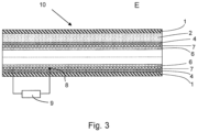
- FIG. 3 A cross-section through an endoscope shaft is shown schematically, whereby compared to the embodiment in Fig. 2 Temperature control is possible for the heating foil 7.
- the heating foil 7 has a temperature sensor 8, by means of which the temperature of the heating foil 7 is detected.
- the heating foil 7 is energized, it is heated, so that the temperature of the heating foil 7 determined by the temperature sensor 8 is transmitted to a temperature control device 9.
- the strength of the electric current for the heating foil 7 is regulated accordingly, so that a preferred temperature in the heating foil is set and kept constant.
Landscapes
- Health & Medical Sciences (AREA)
- Life Sciences & Earth Sciences (AREA)
- Surgery (AREA)
- Physics & Mathematics (AREA)
- Optics & Photonics (AREA)
- Engineering & Computer Science (AREA)
- Biomedical Technology (AREA)
- General Health & Medical Sciences (AREA)
- Pathology (AREA)
- Nuclear Medicine, Radiotherapy & Molecular Imaging (AREA)
- Biophysics (AREA)
- Heart & Thoracic Surgery (AREA)
- Medical Informatics (AREA)
- Molecular Biology (AREA)
- Animal Behavior & Ethology (AREA)
- Radiology & Medical Imaging (AREA)
- Public Health (AREA)
- Veterinary Medicine (AREA)
- Astronomy & Astrophysics (AREA)
- General Physics & Mathematics (AREA)
- Manufacturing & Machinery (AREA)
- Instruments For Viewing The Inside Of Hollow Bodies (AREA)
- Endoscopes (AREA)
Applications Claiming Priority (2)
| Application Number | Priority Date | Filing Date | Title |
|---|---|---|---|
| DE102016202093.5A DE102016202093A1 (de) | 2016-02-11 | 2016-02-11 | Videoendoskop |
| PCT/EP2017/052579 WO2017137362A1 (de) | 2016-02-11 | 2017-02-07 | Videoendoskop |
Publications (2)
| Publication Number | Publication Date |
|---|---|
| EP3413776A1 EP3413776A1 (de) | 2018-12-19 |
| EP3413776B1 true EP3413776B1 (de) | 2025-06-25 |
Family
ID=58018075
Family Applications (1)
| Application Number | Title | Priority Date | Filing Date |
|---|---|---|---|
| EP17704698.4A Active EP3413776B1 (de) | 2016-02-11 | 2017-02-07 | Videoendoskop |
Country Status (5)
| Country | Link |
|---|---|
| US (1) | US20180368667A1 (enExample) |
| EP (1) | EP3413776B1 (enExample) |
| JP (1) | JP6904965B2 (enExample) |
| DE (1) | DE102016202093A1 (enExample) |
| WO (1) | WO2017137362A1 (enExample) |
Families Citing this family (2)
| Publication number | Priority date | Publication date | Assignee | Title |
|---|---|---|---|---|
| CN109116546B (zh) * | 2018-09-10 | 2020-08-21 | 深圳市亚泰光电技术有限公司 | 一种封装蛇骨与编织管的封装结构及封装方法 |
| DE102022118208B4 (de) * | 2022-07-21 | 2024-07-18 | Olympus Winter & Ibe Gmbh | Videoendoskop |
Citations (2)
| Publication number | Priority date | Publication date | Assignee | Title |
|---|---|---|---|---|
| DE202005019684U1 (de) * | 2004-12-31 | 2006-04-13 | Rühland, Dieter, Prof. Dr.med. | Endoskopartige Vorrichtung |
| JP2014131531A (ja) * | 2013-01-04 | 2014-07-17 | Olympus Medical Systems Corp | 内視鏡の曇り防止システムと内視鏡の曇り防止方法 |
Family Cites Families (12)
| Publication number | Priority date | Publication date | Assignee | Title |
|---|---|---|---|---|
| DE3832957A1 (de) * | 1988-09-26 | 1990-03-29 | Schering Ag | Verfahren zur herstellung von metallstrukturierten folien und vorrichtung dafuer |
| JPH02257926A (ja) * | 1989-03-30 | 1990-10-18 | Olympus Optical Co Ltd | 内視鏡装置 |
| JP2000210250A (ja) * | 1999-01-21 | 2000-08-02 | Fujikura Ltd | ファイバスコ―プ |
| JP2002291684A (ja) * | 2001-03-29 | 2002-10-08 | Olympus Optical Co Ltd | 外科手術用内視鏡及び外套管 |
| JP2006000282A (ja) * | 2004-06-16 | 2006-01-05 | Olympus Corp | 内視鏡の曇り防止装置と内視鏡 |
| JP4772313B2 (ja) * | 2004-10-22 | 2011-09-14 | オリンパス株式会社 | 内視鏡可撓管の製造装置及びその製造方法 |
| JP4611193B2 (ja) * | 2005-12-27 | 2011-01-12 | オリンパスメディカルシステムズ株式会社 | 内視鏡装置 |
| DE102008031924B4 (de) * | 2008-07-08 | 2019-06-13 | Olympus Winter & Ibe Gmbh | Endoskop mit Widerstandsheizung |
| CN102131450B (zh) * | 2008-10-24 | 2013-10-30 | 奥林巴斯医疗株式会社 | 内窥镜插入部 |
| JP6140456B2 (ja) * | 2013-01-17 | 2017-05-31 | パナソニック デバイスSunx株式会社 | 同軸型光ファイバヘッド、光ファイバセンサ、同軸型光ファイバヘッドの製造方法 |
| JP6009964B2 (ja) * | 2013-02-15 | 2016-10-19 | オリンパス株式会社 | 内視鏡の曇り防止用ヒータユニットとこのヒータユニットを有する内視鏡 |
| DE102015101624A1 (de) * | 2015-02-04 | 2016-08-04 | Olympus Winter & Ibe Gmbh | Endoskop |
-
2016
- 2016-02-11 DE DE102016202093.5A patent/DE102016202093A1/de active Pending
-
2017
- 2017-02-07 EP EP17704698.4A patent/EP3413776B1/de active Active
- 2017-02-07 WO PCT/EP2017/052579 patent/WO2017137362A1/de not_active Ceased
- 2017-02-07 JP JP2018541626A patent/JP6904965B2/ja active Active
-
2018
- 2018-07-27 US US16/047,138 patent/US20180368667A1/en not_active Abandoned
Patent Citations (2)
| Publication number | Priority date | Publication date | Assignee | Title |
|---|---|---|---|---|
| DE202005019684U1 (de) * | 2004-12-31 | 2006-04-13 | Rühland, Dieter, Prof. Dr.med. | Endoskopartige Vorrichtung |
| JP2014131531A (ja) * | 2013-01-04 | 2014-07-17 | Olympus Medical Systems Corp | 内視鏡の曇り防止システムと内視鏡の曇り防止方法 |
Also Published As
| Publication number | Publication date |
|---|---|
| JP6904965B2 (ja) | 2021-07-21 |
| WO2017137362A1 (de) | 2017-08-17 |
| JP2019506225A (ja) | 2019-03-07 |
| US20180368667A1 (en) | 2018-12-27 |
| EP3413776A1 (de) | 2018-12-19 |
| DE102016202093A1 (de) | 2017-08-17 |
Similar Documents
| Publication | Publication Date | Title |
|---|---|---|
| DE19859155C2 (de) | Endoskop mit einer Koppeleinrichtung (Video-Coupler) zum Anschluß einer Video-Kamera | |
| DE3614615C2 (enExample) | ||
| DE102008031924B4 (de) | Endoskop mit Widerstandsheizung | |
| DE102008031881B3 (de) | Medizinisches Endoskop mit beheiztem Fenster | |
| EP1596703B1 (de) | Verfahren zum montieren eines endoskopes | |
| DE10004869B4 (de) | Verbindungsanordnung für ein Endoskop oder ein Behandlungsinstrument sowie ein Verfahren zum Herstellen derselben | |
| DE10143965B4 (de) | Endoskop | |
| EP0842633B1 (de) | Voll autoklavierbares elektronisches Endoskop | |
| EP3413776B1 (de) | Videoendoskop | |
| DE2841143C2 (enExample) | ||
| DE102016001048B4 (de) | Endoskop | |
| EP0870192A1 (de) | Messeinrichtung | |
| DE102015015041A1 (de) | Endoskop mit einem wiederverwendbaren Teil und einem Einwegteil | |
| WO2015136064A1 (de) | Endoskop mit distaler elektrischer durchführung und verfahren zur montage eines endoskops | |
| WO2020147894A1 (de) | Aktuator für eine endoskopische sonde, endoskopische sonde und verfahren zur steuerung eines aktuators einer endoskopischen sonde | |
| EP1610049B1 (de) | Schlauchverbindungssystem für einen beheizbaren Schlauch | |
| EP3254148A2 (de) | Endoskop | |
| DE102022118208B4 (de) | Videoendoskop | |
| DE112020001676B4 (de) | Endoskop | |
| DE102007002042B4 (de) | Endoskopoptik mit Lichtleitfaserbündel | |
| DE102019100144A1 (de) | Endoskop und Lagesicherungselement | |
| EP2018583B1 (de) | Steckverbinder mit vorrichtung zur kompensation von längenausdehnungen eines lichtwellenleiters | |
| DE202010001630U1 (de) | Endoskopoptik und Endoskop | |
| DE2926919A1 (de) | Endoskop | |
| DE102021105244B3 (de) | Endoskop |
Legal Events
| Date | Code | Title | Description |
|---|---|---|---|
| STAA | Information on the status of an ep patent application or granted ep patent |
Free format text: STATUS: UNKNOWN |
|
| STAA | Information on the status of an ep patent application or granted ep patent |
Free format text: STATUS: THE INTERNATIONAL PUBLICATION HAS BEEN MADE |
|
| PUAI | Public reference made under article 153(3) epc to a published international application that has entered the european phase |
Free format text: ORIGINAL CODE: 0009012 |
|
| STAA | Information on the status of an ep patent application or granted ep patent |
Free format text: STATUS: REQUEST FOR EXAMINATION WAS MADE |
|
| 17P | Request for examination filed |
Effective date: 20180727 |
|
| AK | Designated contracting states |
Kind code of ref document: A1 Designated state(s): AL AT BE BG CH CY CZ DE DK EE ES FI FR GB GR HR HU IE IS IT LI LT LU LV MC MK MT NL NO PL PT RO RS SE SI SK SM TR |
|
| AX | Request for extension of the european patent |
Extension state: BA ME |
|
| DAV | Request for validation of the european patent (deleted) | ||
| DAX | Request for extension of the european patent (deleted) | ||
| STAA | Information on the status of an ep patent application or granted ep patent |
Free format text: STATUS: EXAMINATION IS IN PROGRESS |
|
| 17Q | First examination report despatched |
Effective date: 20210212 |
|
| P01 | Opt-out of the competence of the unified patent court (upc) registered |
Effective date: 20230524 |
|
| GRAP | Despatch of communication of intention to grant a patent |
Free format text: ORIGINAL CODE: EPIDOSNIGR1 |
|
| STAA | Information on the status of an ep patent application or granted ep patent |
Free format text: STATUS: GRANT OF PATENT IS INTENDED |
|
| INTG | Intention to grant announced |
Effective date: 20250131 |
|
| GRAS | Grant fee paid |
Free format text: ORIGINAL CODE: EPIDOSNIGR3 |
|
| GRAA | (expected) grant |
Free format text: ORIGINAL CODE: 0009210 |
|
| STAA | Information on the status of an ep patent application or granted ep patent |
Free format text: STATUS: THE PATENT HAS BEEN GRANTED |
|
| AK | Designated contracting states |
Kind code of ref document: B1 Designated state(s): AL AT BE BG CH CY CZ DE DK EE ES FI FR GB GR HR HU IE IS IT LI LT LU LV MC MK MT NL NO PL PT RO RS SE SI SK SM TR |
|
| REG | Reference to a national code |
Ref country code: GB Ref legal event code: FG4D Free format text: NOT ENGLISH |
|
| REG | Reference to a national code |
Ref country code: CH Ref legal event code: EP |
|
| REG | Reference to a national code |
Ref country code: DE Ref legal event code: R096 Ref document number: 502017016920 Country of ref document: DE |
|
| REG | Reference to a national code |
Ref country code: CH Ref legal event code: EP |
|
| REG | Reference to a national code |
Ref country code: IE Ref legal event code: FG4D Free format text: LANGUAGE OF EP DOCUMENT: GERMAN |
|
| PG25 | Lapsed in a contracting state [announced via postgrant information from national office to epo] |
Ref country code: FI Free format text: LAPSE BECAUSE OF FAILURE TO SUBMIT A TRANSLATION OF THE DESCRIPTION OR TO PAY THE FEE WITHIN THE PRESCRIBED TIME-LIMIT Effective date: 20250625 |
|
| REG | Reference to a national code |
Ref country code: LT Ref legal event code: MG9D |
|
| PG25 | Lapsed in a contracting state [announced via postgrant information from national office to epo] |
Ref country code: GR Free format text: LAPSE BECAUSE OF FAILURE TO SUBMIT A TRANSLATION OF THE DESCRIPTION OR TO PAY THE FEE WITHIN THE PRESCRIBED TIME-LIMIT Effective date: 20250926 Ref country code: NO Free format text: LAPSE BECAUSE OF FAILURE TO SUBMIT A TRANSLATION OF THE DESCRIPTION OR TO PAY THE FEE WITHIN THE PRESCRIBED TIME-LIMIT Effective date: 20250925 |
|
| PG25 | Lapsed in a contracting state [announced via postgrant information from national office to epo] |
Ref country code: BG Free format text: LAPSE BECAUSE OF FAILURE TO SUBMIT A TRANSLATION OF THE DESCRIPTION OR TO PAY THE FEE WITHIN THE PRESCRIBED TIME-LIMIT Effective date: 20250625 |
|
| PG25 | Lapsed in a contracting state [announced via postgrant information from national office to epo] |
Ref country code: HR Free format text: LAPSE BECAUSE OF FAILURE TO SUBMIT A TRANSLATION OF THE DESCRIPTION OR TO PAY THE FEE WITHIN THE PRESCRIBED TIME-LIMIT Effective date: 20250625 |
|
| PG25 | Lapsed in a contracting state [announced via postgrant information from national office to epo] |
Ref country code: RS Free format text: LAPSE BECAUSE OF FAILURE TO SUBMIT A TRANSLATION OF THE DESCRIPTION OR TO PAY THE FEE WITHIN THE PRESCRIBED TIME-LIMIT Effective date: 20250925 |
|
| PG25 | Lapsed in a contracting state [announced via postgrant information from national office to epo] |
Ref country code: LV Free format text: LAPSE BECAUSE OF FAILURE TO SUBMIT A TRANSLATION OF THE DESCRIPTION OR TO PAY THE FEE WITHIN THE PRESCRIBED TIME-LIMIT Effective date: 20250625 |
|
| REG | Reference to a national code |
Ref country code: NL Ref legal event code: MP Effective date: 20250625 |
|
| PG25 | Lapsed in a contracting state [announced via postgrant information from national office to epo] |
Ref country code: NL Free format text: LAPSE BECAUSE OF FAILURE TO SUBMIT A TRANSLATION OF THE DESCRIPTION OR TO PAY THE FEE WITHIN THE PRESCRIBED TIME-LIMIT Effective date: 20250625 |
|
| PG25 | Lapsed in a contracting state [announced via postgrant information from national office to epo] |
Ref country code: PT Free format text: LAPSE BECAUSE OF FAILURE TO SUBMIT A TRANSLATION OF THE DESCRIPTION OR TO PAY THE FEE WITHIN THE PRESCRIBED TIME-LIMIT Effective date: 20251027 |