EP3412414A2 - Steuerungssystem eines robotersystems sowie robotersystem - Google Patents
Steuerungssystem eines robotersystems sowie robotersystem Download PDFInfo
- Publication number
- EP3412414A2 EP3412414A2 EP18175990.3A EP18175990A EP3412414A2 EP 3412414 A2 EP3412414 A2 EP 3412414A2 EP 18175990 A EP18175990 A EP 18175990A EP 3412414 A2 EP3412414 A2 EP 3412414A2
- Authority
- EP
- European Patent Office
- Prior art keywords
- control
- parts
- feeder
- robot
- partition
- Prior art date
- Legal status (The legal status is an assumption and is not a legal conclusion. Google has not performed a legal analysis and makes no representation as to the accuracy of the status listed.)
- Ceased
Links
Images












Classifications
-
- B—PERFORMING OPERATIONS; TRANSPORTING
- B25—HAND TOOLS; PORTABLE POWER-DRIVEN TOOLS; MANIPULATORS
- B25J—MANIPULATORS; CHAMBERS PROVIDED WITH MANIPULATION DEVICES
- B25J9/00—Program-controlled manipulators
- B25J9/0093—Program-controlled manipulators co-operating with conveyor means
-
- B—PERFORMING OPERATIONS; TRANSPORTING
- B25—HAND TOOLS; PORTABLE POWER-DRIVEN TOOLS; MANIPULATORS
- B25J—MANIPULATORS; CHAMBERS PROVIDED WITH MANIPULATION DEVICES
- B25J9/00—Program-controlled manipulators
- B25J9/16—Program controls
- B25J9/1679—Program controls characterised by the tasks executed
- B25J9/1687—Assembly, peg and hole, palletising, straight line, weaving pattern movement
-
- B—PERFORMING OPERATIONS; TRANSPORTING
- B23—MACHINE TOOLS; METAL-WORKING NOT OTHERWISE PROVIDED FOR
- B23P—METAL-WORKING NOT OTHERWISE PROVIDED FOR; COMBINED OPERATIONS; UNIVERSAL MACHINE TOOLS
- B23P19/00—Machines for simply fitting together or separating metal parts or objects, or metal and non-metal parts, whether or not involving some deformation; Tools or devices therefor so far as not provided for in other classes
- B23P19/001—Article feeders for assembling machines
- B23P19/007—Picking-up and placing mechanisms
-
- B—PERFORMING OPERATIONS; TRANSPORTING
- B25—HAND TOOLS; PORTABLE POWER-DRIVEN TOOLS; MANIPULATORS
- B25J—MANIPULATORS; CHAMBERS PROVIDED WITH MANIPULATION DEVICES
- B25J13/00—Controls for manipulators
-
- B—PERFORMING OPERATIONS; TRANSPORTING
- B25—HAND TOOLS; PORTABLE POWER-DRIVEN TOOLS; MANIPULATORS
- B25J—MANIPULATORS; CHAMBERS PROVIDED WITH MANIPULATION DEVICES
- B25J13/00—Controls for manipulators
- B25J13/08—Controls for manipulators by means of sensing devices, e.g. viewing or touching devices
-
- B—PERFORMING OPERATIONS; TRANSPORTING
- B25—HAND TOOLS; PORTABLE POWER-DRIVEN TOOLS; MANIPULATORS
- B25J—MANIPULATORS; CHAMBERS PROVIDED WITH MANIPULATION DEVICES
- B25J9/00—Program-controlled manipulators
- B25J9/16—Program controls
- B25J9/1656—Program controls characterised by programming, planning systems for manipulators
- B25J9/1664—Program controls characterised by programming, planning systems for manipulators characterised by motion, path, trajectory planning
-
- B—PERFORMING OPERATIONS; TRANSPORTING
- B25—HAND TOOLS; PORTABLE POWER-DRIVEN TOOLS; MANIPULATORS
- B25J—MANIPULATORS; CHAMBERS PROVIDED WITH MANIPULATION DEVICES
- B25J9/00—Program-controlled manipulators
- B25J9/16—Program controls
- B25J9/1694—Program controls characterised by use of sensors other than normal servo-feedback from position, speed or acceleration sensors, perception control, multi-sensor controlled systems, sensor fusion
- B25J9/1697—Vision controlled systems
-
- G—PHYSICS
- G05—CONTROLLING; REGULATING
- G05B—CONTROL OR REGULATING SYSTEMS IN GENERAL; FUNCTIONAL ELEMENTS OF SUCH SYSTEMS; MONITORING OR TESTING ARRANGEMENTS FOR SUCH SYSTEMS OR ELEMENTS
- G05B19/00—Program-control systems
- G05B19/02—Program-control systems electric
- G05B19/418—Total factory control, i.e. centrally controlling a plurality of machines, e.g. direct or distributed numerical control [DNC], flexible manufacturing systems [FMS], integrated manufacturing systems [IMS] or computer integrated manufacturing [CIM]
- G05B19/41815—Total factory control, i.e. centrally controlling a plurality of machines, e.g. direct or distributed numerical control [DNC], flexible manufacturing systems [FMS], integrated manufacturing systems [IMS] or computer integrated manufacturing [CIM] characterised by the cooperation between machine tools, manipulators and conveyor or other workpiece supply system, workcell
- G05B19/4182—Total factory control, i.e. centrally controlling a plurality of machines, e.g. direct or distributed numerical control [DNC], flexible manufacturing systems [FMS], integrated manufacturing systems [IMS] or computer integrated manufacturing [CIM] characterised by the cooperation between machine tools, manipulators and conveyor or other workpiece supply system, workcell manipulators and conveyor only
-
- B—PERFORMING OPERATIONS; TRANSPORTING
- B65—CONVEYING; PACKING; STORING; HANDLING THIN OR FILAMENTARY MATERIAL
- B65G—TRANSPORT OR STORAGE DEVICES, e.g. CONVEYORS FOR LOADING OR TIPPING, SHOP CONVEYOR SYSTEMS OR PNEUMATIC TUBE CONVEYORS
- B65G47/00—Article or material-handling devices associated with conveyors; Methods employing such devices
- B65G47/02—Devices for feeding articles or materials to conveyors
- B65G47/04—Devices for feeding articles or materials to conveyors for feeding articles
- B65G47/12—Devices for feeding articles or materials to conveyors for feeding articles from disorderly-arranged article piles or from loose assemblages of articles
- B65G47/14—Devices for feeding articles or materials to conveyors for feeding articles from disorderly-arranged article piles or from loose assemblages of articles arranging or orientating the articles by mechanical or pneumatic means during feeding
- B65G47/1407—Devices for feeding articles or materials to conveyors for feeding articles from disorderly-arranged article piles or from loose assemblages of articles arranging or orientating the articles by mechanical or pneumatic means during feeding the articles being fed from a container, e.g. a bowl
- B65G47/1414—Devices for feeding articles or materials to conveyors for feeding articles from disorderly-arranged article piles or from loose assemblages of articles arranging or orientating the articles by mechanical or pneumatic means during feeding the articles being fed from a container, e.g. a bowl by means of movement of at least the whole wall of the container
- B65G47/1421—Vibratory movement
-
- G—PHYSICS
- G05—CONTROLLING; REGULATING
- G05B—CONTROL OR REGULATING SYSTEMS IN GENERAL; FUNCTIONAL ELEMENTS OF SUCH SYSTEMS; MONITORING OR TESTING ARRANGEMENTS FOR SUCH SYSTEMS OR ELEMENTS
- G05B2219/00—Program-control systems
- G05B2219/30—Nc systems
- G05B2219/39—Robotics, robotics to robotics hand
- G05B2219/39102—Manipulator cooperating with conveyor
-
- G—PHYSICS
- G05—CONTROLLING; REGULATING
- G05B—CONTROL OR REGULATING SYSTEMS IN GENERAL; FUNCTIONAL ELEMENTS OF SUCH SYSTEMS; MONITORING OR TESTING ARRANGEMENTS FOR SUCH SYSTEMS OR ELEMENTS
- G05B2219/00—Program-control systems
- G05B2219/30—Nc systems
- G05B2219/39—Robotics, robotics to robotics hand
- G05B2219/39241—Force and vibration control
-
- Y—GENERAL TAGGING OF NEW TECHNOLOGICAL DEVELOPMENTS; GENERAL TAGGING OF CROSS-SECTIONAL TECHNOLOGIES SPANNING OVER SEVERAL SECTIONS OF THE IPC; TECHNICAL SUBJECTS COVERED BY FORMER USPC CROSS-REFERENCE ART COLLECTIONS [XRACs] AND DIGESTS
- Y02—TECHNOLOGIES OR APPLICATIONS FOR MITIGATION OR ADAPTATION AGAINST CLIMATE CHANGE
- Y02P—CLIMATE CHANGE MITIGATION TECHNOLOGIES IN THE PRODUCTION OR PROCESSING OF GOODS
- Y02P90/00—Enabling technologies with a potential contribution to greenhouse gas [GHG] emissions mitigation
- Y02P90/02—Total factory control, e.g. smart factories, flexible manufacturing systems [FMS] or integrated manufacturing systems [IMS]
Definitions
- the present invention relates to control of a robot system that handles a part (component).
- JP-A-60-200385 discloses a technique in which a robot picks up a part (component) from a part feeder and performs assembly work.
- the part in a swivel part feeder is imaged by a camera, and presence or absence, a position, and a posture of the part are recognized by an image process. Then, the robot executes a grasp and the assembly work of the part based on a recognition result.
- An advantage of some aspects of the invention is to solve at least a part of the problems described above, and the invention can be implemented as the following aspects.
- the robot system it is also possible to appropriately operate the part feeder according to the type and the shape of the part. Alternatively, it is possible to improve the efficiency of work of picking up the part from the part feeder.
- the invention can be realized in various aspects other than the above.
- the invention can be realized in an aspect such as a computer program for realizing functions of the control apparatus and a non-transitory storage medium in which the computer program is recorded.
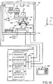
- Fig. 1 is a conceptual diagram of a robot system in a first embodiment.
- the robot system is mounted on a stand 700 and includes a robot 100, a control apparatus 200, a teaching pendant 300, a part feeder 400, a hopper 500, and a part tray 600.
- the robot 100 is fixed under a top plate 710 of the stand 700.
- the part feeder 400, the hopper 500, and the part tray 600 are mounted on a table portion 720 of the stand 700.
- the robot 100 is a teaching playback type robot.
- the work using the robot 100 is executed according to teaching data created in advance .
- a system coordinate system ⁇ s defined by three coordinate axes X, Y, and Z orthogonal to each other is set in the robot system. In an example of Fig.
- X-axis and Y-axis are in the horizontal direction, and Z-axis is in the vertical upper direction.
- a teaching point included in the teaching data and a posture of an end effector are expressed by a coordinate value of the system coordinate system ⁇ s and an angle around each axis.
- the robot 100 includes a base 120 and an arm 130.
- the arm 130 is sequentially connected by four joints J1 to J4.
- the three joints J1, J2, and J4 are torsional joints, and one joint J3 is a translational joint among the joints J1 to J4.
- a four-axis robot is exemplified in the embodiment, but it is possible to use a robot having an optional arm mechanism including one or more joints.
- An end effector 160a is attached to an arm end 132 which is a tip end portion of the arm 130.
- the end effector 160a is an adsorption pick-up mechanism having an adsorption nozzle 162 that vacuum-adsorbs a part.
- a camera 180 is further attached to the arm 130. The camera 180 is used when a part required to be picked up is selected when a part is picked up by the end effector 160a. However, the camera 180 can be omitted.
- the part feeder 400 includes a part accommodating unit 410 that accommodates the part and a vibration unit 420 that vibrates the part accommodating unit 410.
- a camera 430 for capturing an image of the part in the part accommodating unit 410 is mounted under the top plate 710 of the stand 700.
- the hopper 500 is a part replenishment apparatus that replenishes the part to the part feeder 400.
- the term "hopper” is not limited to an apparatus having a funnel shape and is used as a term indicating an apparatus to replenish the part.
- the part tray 600 is a tray having a large number of recessed portions for individually accommodating parts.
- the robot 100 picks up the part from the part accommodating unit 410 of the part feeder 400 and executes work of storing the part in an appropriate position in the part tray 600.
- the robot system can be also employed in a case of performing another work other than the above work.
- the control apparatus 200 includes a processor 210, a main memory 220, a non-volatile memory 230, a display control unit 240, a display unit 250, and an I/O interface 260. Each of units is connected through a bus.
- the processor 210 is, for example, a microprocessor or a processor circuit.
- the control apparatus 200 is connected to the robot 100, the teaching pendant 300, the part feeder 400, and the hopper 500 through the I/O interface 260.
- the control apparatus 200 is further connected to cameras 180 and 430 through the I/O interface 260.
- the control apparatus 200 it is possible to employ various configurations other than the configuration illustrated in Fig. 1 .
- the processor 210 and the main memory 220 may be removed from the control apparatus 200 of Fig. 1 , and the processor 210 and the main memory 220 may be provided in another apparatus connected to the control apparatus 200 in a communicable manner.
- the entire apparatus including another apparatus and the control apparatus 200 functions as the control apparatus of the robot 100.
- the control apparatus 200 may include two or more processors 210.
- the control apparatus 200 may be realized by a plurality of apparatuses connected to each other in a communicable manner.
- the control apparatus 200 is configured as an apparatus including one or more processors 210 or a group of apparatuses.
- the teaching pendant 300 is a type of a robot teaching apparatus used when human teaching worker teaches an operation of the robot 100.
- the teaching pendant 300 includes a processor and a memory (not illustrated) .
- Teaching data created by the teaching using the teaching pendant 300 is stored in the non-volatile memory 230 of the control apparatus 200.
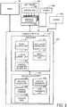
- Fig. 2 is a block diagram illustrating functions of the control apparatus 200.
- the processor 210 of the control apparatus 200 executes various program instructions 231 stored in advance in the non-volatile memory 230 to respectively realize the functions of a robot control unit 211, a part feeder control unit 212, a hopper control unit 213, an image recognition unit 214, and a control parameter setting unit 215.
- the functions of above units 211 to 215 will be described below.
- the part feeder 400 includes a control unit 422 and a plurality of vibration actuators 424.
- the plurality of vibration actuators 424 are vibrators that vibrate the part accommodating unit 410 ( Fig. 1 ).
- the non-volatile memory 230 stores a control parameter 232 and a control command 233 of the vibration actuator 424, and a part coordinate list 234 in addition to the program instruction 231 and teaching data 235.
- the control parameter 232, the control command 233, and the part coordinate list 234 will be described below.
- the robot control unit 211, the part feeder control unit 212, and the hopper control unit 213 control the work of each unit according to the teaching data 235.
- Fig. 3 is a plan view of the part accommodating unit 410.
- the part accommodating unit 410 includes a part accommodating region 412 and an outer peripheral wall 414 provided on the outer periphery of the part accommodating region 412 and extending in the Z direction.
- the part accommodating region 412 is a flat substantially rectangular region.
- the X direction is the longitudinal direction of the part accommodating region 412
- the Y direction is the transverse direction of the part accommodating region 412. It is preferable to maintain a surface of the part accommodating region 412 horizontally in order to stably accommodate the part.
- the part accommodating region 412 is also referred to as "platform".
- the plurality of vibration actuators 424a to 424d are mounted under the part accommodating region 412.
- Open circles indicating the vibration actuators 424a to 424d indicate planar positions of the vibration actuators 424a to 424d under the part accommodating region 412.
- the vibration actuators 424a to 424d are mounted under the part accommodating region 412 in an invisible state.
- the number of the vibration actuators is four, and the vibration actuators are mounted at four corners of the part accommodating region 412.
- the number of the vibration actuators is not limited to four, and the optional number of vibration actuators may be provided.
- the small letters “a” to “d” attached to the end of the reference signs of the plurality of vibration actuators 424a to 424d are additional reference signs attached in order to distinguish each vibration actuator.
- the "a” at the end of the reference sign of the end effector 160a is also an additional reference sign attached in order to distinguish the end effector 160a from the end effector used in another embodiment.
- "a" to "d” and the like are omitted in a case where such additional sign is unnecessary.
- the part accommodating region 412 is divided into three virtual partitions RA, RB, and RC. It is preferable that boundary lines between adjacent partitions are set parallel to the transverse direction (Y direction) of the part accommodating region 412.
- a picking partition RA is a partition where the end effector 160a picks up the part.
- a replenishment partition RC is a partition that receives the replenishment of the part from the hopper 500.
- the intermediate partition RB is a partition provided between the picking partition RA and the replenishment partition RC. It is preferable that widths (dimension in the X direction) of the partitions are set to be equal to each other. Specifically, when an average value of the widths of the plurality of partitions RA to RC is 100%, it is preferable that the width of each partition is in a range of 100% ⁇ 10%.
- the "takt time" is a time required for one piece of work in a case where the work in which the robot 100 picks up a part from the part feeder 400 and stores the part in the part tray 600 is repeated a plurality of times.
- a partition closest to the part tray 600 is commonly selected as the picking partition RA among the plurality of partitions RA to RC.
- the number of partitions provided in the part accommodating region 412 is not limited to three and may be two or four or more.
- the part accommodating region 412 may be not divided into the plurality of partitions.
- the boundary lines of the plurality of partitions are set parallel to the transverse direction (X direction) in the example of Fig. 3 , but the boundary lines of the plurality of partitions may be set parallel to the longitudinal direction (Y direction) instead of the example.
- the boundary lines parallel to the transverse direction (X direction) and the boundary lines parallel to the longitudinal direction (Y direction) may be respectively set as the boundary lines of the plurality of partitions.
- the plurality of partitions may be disposed in a 2 ⁇ 2 checkerboard form.
- the part feeder 400 is configured to be able to perform various operations according to various control commands transmitted from the part feeder control unit 212 of the control apparatus 200.
- Each control command is configured to include, for example, the following control parameters.
- the "vibration signal” is a signal provided from the control unit 422 of the part feeder 400 to each vibration actuator 424, and each vibration actuator 424 vibrates according to the vibration signal.
- a waveform of the vibration signal suitable for each operation also exists as the control parameter of the vibration actuator 424.
- the waveform of the vibration signal selected by each control command is stored in advance, for example, in a non-volatile memory (not illustrated) in the control unit 422 ( Fig. 2 ) of the part feeder 400.
- the control unit 422 selects the waveform of the vibration signal according to the control command supplied from the control apparatus 200.
- a control command including parameters for selecting one waveform from waveforms of a plurality of types of vibration signals stored in the control unit 422 may be transmitted from the control apparatus 200 to the control unit 422 of the part feeder 400.
- vibration actuator 424 The control parameter of the vibration actuator 424 is also referred to as "vibration parameter".
- Fig. 4A is an explanatory diagram illustrating a feed operation by the feed command.
- vibration actuators having black circles added in the open circles vibrate in the feed operation
- vibration actuators having no added black circles do not vibrate. This is also the same as in another operation to be described below.
- the two vibration actuators 424c and 424d at the right end of the longitudinal direction (X direction) of the part accommodating region 412 vibrate, and the two vibration actuators 424a and 424b at the left end thereof do not vibrate.
- the two operating vibration actuators 424c and 424d vibrate with the same phase.
- a part PP in the part accommodating region 412 moves in a direction from the right to the left (-X direction) .
- control parameters included in the feed command are, for example, as follows.
- Fig. 4B is an explanatory diagram illustrating a separation operation by the separation command.
- the plurality of vibration actuators 424a to 424d simultaneously operate in the separation operation.
- the four vibration actuators 424a to 424d vibrate in the same phase .
- In the separation operation it is possible to separate a plurality of parts PP gathered in the part accommodating region 412.
- the efficiency of work of picking up the part from the part feeder 400 can be improved by separating the parts PP from each other using such a separation command.
- control parameters included in the separation command are, for example, as follows.
- Fig. 4C is an explanatory diagram illustrating a flip operation by the flip command.
- the plurality of vibration actuators 424a to 424d simultaneously operate in the flip operation.
- the four vibration actuators 424a to 424d vibrate in the same phase.
- the flip operation it is possible to invert the part PP in the part accommodating region 412.
- a sandy pattern part PPf is a forward-facing part
- a shaded hatching part PPb is a backward-facing part.
- the flip operation is an operation to invert the parts PP.
- control parameters included in the flip command are, for example, as follows.
- the vibration continuing period is set shorter than in the separation command. That is, the vibration continuing period of the vibration actuator 424 in the separation command is set longer than in the flip command.
- a waveform of the vibration signal supplied to the vibration actuator 424 according to the flip command is a waveform that can invert the part PP.
- the flip command is a type of a posture change command that changes a posture of the part PP.
- the posture change command other than the flip command it is possible to use, for example, a rotation command that rotates the part PP on the surface of the part accommodating region 412.
- the part PP rotates around the vertical direction (Z direction) in a rotation operation by the rotation command.
- the posture change command other than the flip command such as the rotation command is effective when the part PP is picked up using a gripping mechanism that grips the part PP.
- the posture of the part PP is changed using the posture change command, it is possible to improve the efficiency of the work of picking up the part PP.
- the separation command and the posture change command such as the flip command are used, it is possible to improve the efficiency of the work of picking up the part. Since the vibration continuing period of the vibration actuators in the separation command is set longer than in the posture change command such as the flip command, it is possible to separate the parts successfully.
- Fig. 4D is an explanatory diagram illustrating a centering operation by the centering command.
- the plurality of vibration actuators 424a to 424d simultaneously operate in the centering operation.
- the vibration actuators 424a and 424b at one end portion in the X direction vibrate at a phase different by 180° from the vibration actuators 424c and 424d at the other end portion in the X direction in order to move the parts PP to the center of the longitudinal direction (X direction) of the part accommodating region 412.
- the vibration actuators 424a and 424c at one end portion in the Y direction vibrate at a phase different by 180° from the vibration actuators 424b and 424d at the other end portion in the Y direction.
- control parameters included in the centering command are, for example, as follows.
- the “purpose of the centering operation” it is possible to set two different purposes, for example, (a) gathering the parts PP at the center of part accommodating region 412 as a pre-process of the separation operation described in Fig. 4B and (b) moving the parts PP existing in an interference region (will be described in third embodiment) which is in the outer periphery of the part accommodating region 412 to the inside of the part accommodating region 412 after the separation operation.
- the vibration continuing times in the centering operations having the different purposes are set to appropriate times according to the respective purposes.
- the part feeder control unit 212 selects one or more control commands from the plurality of control commands respectively including the control parameters of the plurality of vibration actuators 424 and transmits the selected control command to the part feeder 400 for causing the part feeder 400 to perform an operation according to the selected control command. Accordingly, it is possible to transmit the control parameters suitable for the operation of the part feeder 400 to the part feeder 400. As a result, it is possible to appropriately operate the part feeder 400 according to a type and a shape of the part PP. Alternatively, it is possible to improve the efficiency of the work of picking up the part PP from the part feeder 400.
- control parameters suitable for each control command are stored in the non-volatile memory 230 set in advance by the control parameter setting unit 215 before the robot 100 performs the pick-up work of the part PP.
- An initial setting of such control parameters will be described after various embodiments relating to the pick-up work of the part PP.
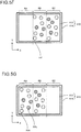
- Figs. 5A to 5H are explanatory diagrams illustrating states where the parts move in the part accommodating region 412 in the pick-up work of the part PP by the robot 100.
- the illustration of the vibration actuator 424 is omitted in Figs. 5A to 5H .
- Fig. 5A illustrates an initial state where parts PP are initially replenished from the hopper 500 to the part accommodating region 412.
- the hopper 500 replenishes a plurality of parts PP in the replenishment partition RC.
- the sandy pattern parts PP are the forward-facing parts
- the shaded hatching parts PP are the backward-facing parts.
- the parts PP can be uniformly dispersed only by the separation operation depending on the type and the number of parts PP, a supply method, and a supply position. In such a case, the centering operation may be omitted.
- the forward-facing parts PPf and the backward-facing parts PPb in each of partitions RA, RB, and RC.
- the work of the robot 100 in the embodiment is to pick up the forward-facing parts PPf and to store the parts in the part tray 600. Detection of the forward-facing parts PPf and the backward-facing parts PPb is performed by the image recognition unit 214 executing an image recognition process on an image acquired by the camera 430.
- Fig. 5D illustrates a state where the robot 100 picks up all the forward-facing parts PPf existing in the picking partition RA from the state of Fig. 5C .
- a state of Fig. 5E is obtained.
- the parts PP existing in the partitions RB and RC are in the same state as in Fig. 5D to simplify the figure.
- the parts PP in the partitions RB and RC are actually inverted by the flip operation.
- the parts PPf which are turned forward-facing by the flip operation are picked up from the picking partition RA by the robot 100.
- the flip operation and the pick-up operation of the parts PP are repeated until the picking up of all the parts PP in the picking partition RA is completed.
- Fig. 5F illustrates a state where the picking up of all the parts PP in the picking partition RA is completed.
- a state of Fig. 5G is obtained.
- the feed operation is executed so as to move the parts PP from respective partitions RB and RC to respective adjacent partitions RA and RB.
- the pick-up operation and the flip operation of the parts PP described in Figs. 5C to 5F are performed with respect to the parts PP existing in the picking partition RA, and all the parts PP in the picking partition RA are picked up.
- the state of Fig. 5G illustrates a state where the picking up of all the parts PP in the picking partition RA is completed.
- the part PP since there is no part PP in the replenishment partition RC, the part PP may be replenished from the hopper 500 to the replenishment partition RC in parallel with the pick-up operation and the flip operation of the parts PP in the picking partition RA.
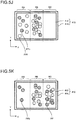
- Fig. 5H illustrates a state where the picking up of the forward-facing parts PPf in the picking partition RA in Fig. 5G is completed and the parts PP are replenished to the replenishment partition RC.
- a state of Fig. 5I is obtained.
- a state of Fig. 5J is obtained.
- Fig. 5K illustrates a state where the picking up of the forward-facing parts PPf in the picking partition RA in Fig. 5J is completed and the parts PP are replenished to the replenishment partition RC.
- the parts PP existing in the intermediate partition RB in Fig. 5K are the parts replenished to the replenishment partition RC in Fig. 5I .
- the number of parts PP replenished to the replenishment partition RC respectively in Figs. 5I and 5K is experimentally determined in advance and stored in the non-volatile memory 230. In the embodiment, the number of replenishments per time is set, for example, to a value of 1/2 of the number of initial replenishments in Fig. 5A .
- N 412 is integer of two or more partitions
- the number of replenishments per time after the second time is commonly set to a value of 1/ (N 412 - 1) of the number of initial replenishments.
- the number of parts PP picked up from the part accommodating region 412 may be used as the number of replenishments instead of setting the number of replenishments of the parts PP to a constant value.
- the number of parts PP picked up during a period from a previous replenishment time to a current replenishment time may be the number of replenishments. In this manner, since the number of parts PP existing in the part accommodating region 412 after the replenishment is constant, the efficiency of the pick-up work improves.
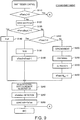
- Fig. 6 is a flowchart of part feeder control in the first embodiment. The control is executed by the part feeder control unit 212 unless otherwise stated. The control of Fig. 6 is repeatedly executed, for example, for each constant time.
- step S110 it is determined whether the detected number nParts of forward-facing parts PPf in the picking partition RA is one or more.
- the nParts is a value detected in step S240 described below, and an initial value (default value) thereof is zero.
- a process of Fig. 6 is ended, and the pick-up operation of the parts PP by the robot 100 is executed.
- the process proceeds to step S120 since the nParts is zero.
- step S120 the synchronous control parameter syncLock is set to true, and the pick-up operation of the robot 100 is prohibited.
- step S130 it is determined whether the detected number nPartsBack of backward-facing parts PPb in the picking partition RA is one or more.
- the nPartsBack is a value detected in step S250 described below, and an initial value (default value) thereof is zero.
- the flip operation is executed in step S140, and the process proceeds to step S240.
- the flip operation to invert the parts PP is executed.
- step S140 another type of posture change operation may be performed instead of the flip operation. This will be described in a third embodiment.
- step S180 it is determined whether the counter value nFeed of the feed operation is one or more.
- the nFeed is set in step S230 described below and a value changed in step S160, and an initial value (default value) thereof is zero. In a case where the nFeed is one or more, the process proceeds to step S150 described below.
- the determination in step S180 is executed for the first time, the nFeed is zero and the process proceeds to step S190.
- step S190 it is determined whether the process after step S190 is executed for the first time. In a case where the process after step S190 is the first time, the process proceeds to step S200 and an initial part replenishment is executed from the hopper 500 to the part feeder 400. The part replenishment is the operation described in Fig. 5A and is executed by the hopper control unit 213 transmitting the control command to the hopper 500. In a case where the process after step S190 is not the first time, the process skips step S200 and proceeds to step S210.
- step S230 the nFeed is set to (N 412 - 1) .
- step S150 in a case where the nFeed is one or more, the process proceeds to step S150.
- the case where the nFeed is one or more is the states in Figs. 5F and 5I described above.
- the feed operation is performed in step S150
- the nFeed is decremented by one in step S160
- the part replenishment is performed in step S170.
- the part replenishment is the operations described in Figs. 5H and 5K .
- step S170 may be executed after permitting the pick-up operation of the robot 100 in step S260 described below.
- step S240 the number nParts of forward-facing parts PPf in the picking partition RA is detected.
- the detection process is performed by the image recognition unit 214 executing the image recognition for recognizing the parts PP existing in the picking partition RA using an image captured by the camera 430.
- the image recognition can be realized, for example, by storing template images of the forward-facing part PPf and the backward-facing part PPb in the non-volatile memory 230 in advance and executing template matching with respect to the image captured by the camera 430.
- the detected number is set as the value of nParts, and a coordinate of the detected forward-facing part PPf is registered in the part coordinate list 234 ( Fig. 2 ).
- a coordinate value of the system coordinate system ⁇ s ( Fig. 1 ) is used as the coordinate of the forward-facing part PPf.
- the number nPartsBack of backward-facing parts PPb in the picking partition RA is detected.
- the detection process is also performed by the image recognition unit 214 executing the image recognition for recognizing the parts PP existing in the picking partition RA using an image captured by the camera 430.
- the detected number is set as the value of nPartsBack.
- step S260 the syncLock is set to false, the pick-up operation of the robot 100 is permitted, and the process of Fig. 6 is ended.
- step S190 in a case where it is determined that the process is not the first time, the pick-up work of the parts in the picking partition RA is completed, and the number of parts in the part accommodating region 412 is small.
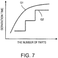
- a time during the separation operation (refer to as "separation time") in step S220 may be shorter than a separation time in the case of executing step S220 for the first time.
- Fig. 7 illustrates examples of graphs G1 and G2 indicating a relationship between the number of parts in the part accommodating region 412 and the separation time. Both the graphs G1 and G2 indicate the characteristics that the separation time becomes shorter as the number of parts is smaller.
- the graph G1 is a curve projected upward, and the graph G2 is stepwise.
- the number of parts in the part accommodating region 412 can be obtained by the image recognition process using the camera 430 ( Fig. 1 ). In this manner, when the separation time is set to be shorter as the number of parts in the part accommodating region 412 is smaller, the overall work time can be further shortened.
- Fig. 8 is a flowchart of the robot control in the first embodiment.
- the control is executed by the robot control unit 211.
- the control of Fig. 8 is repeatedly executed, for example, for each constant time.
- step S310 the process waits until the syncLock changes from true (operation prohibition) to false (operation permission) .
- step S320 a coordinate of one part PP to be picked up by the robot 100 is taken out from the part coordinate list 234.
- step S330 one part PP is picked up using an end effector 160.
- step S340 the picked up part PP is moved to a target position.
- the target position is an empty position in the part tray 600.
- step S170 may be executed after step S260.
- the part feeder control unit 212 causes the part feeder 400 to perform various operations such as the flip operation (step S140), the feed operation (step S150), the centering operation (step S210), and the separation operation (step S220) using a result of the image recognition by the image recognition unit 214, but may cause the part feeder 400 to perform operations other than these operations.
- the part feeder control unit 212 selects one or more control commands from the plurality of control commands and transmits the selected command to the part feeder also using the result of the image recognition with respect to the image of the parts PP in the part accommodating unit 410 acquired by the camera 430. In this manner, since the part in the part accommodating unit 410 is recognized by the image recognition, it is possible to transmit an appropriate control command according to the recognized result to the part feeder 400 to operate the part feeder 400 appropriately.
- Fig. 9 is a flowchart of part feeder control in a second embodiment. Difference from the flowchart of the first embodiment illustrated in Fig. 6 is that only steps S170 and S190 are removed, and other steps are the same as the steps in Fig. 6 .
- step S200 when a first part replenishment is performed in step S200, new parts are not replenished until all the replenished parts are picked up.
- the replenishment is executed again in step S200 after all the parts in the part accommodating region 412 are picked up. According to the second embodiment, substantially the same effect as the first embodiment can be obtained.
- Fig. 10 is a conceptual diagram of a robot system in a third embodiment.
- the robot system is the same as the robot system of the first embodiment ( Fig. 1 ) except for the end effector 160b.
- the end effector 160b is a gripper that grips and picks up a part using a gripping mechanism 164.
- Fig. 11 is a flowchart of part feeder control in the third embodiment. Difference from the flowchart of the first embodiment illustrated in Fig. 6 is that only step S225 is added between steps S220 and S230, and other steps are the same as the steps in Fig. 6 . In a state where the separation operation in step S220 is ended, the parts PP are almost uniformly dispersed in the part accommodating region 412.
- Fig. 12A illustrates a state where the separation operation of step S220 is ended in the third embodiment.
- Three recessed portions around each part PP indicate places gripped by the gripping mechanism 164 of the end effector 160b.
- the gripping mechanism 164 a mechanism that grips with two points may be used instead of the mechanism that grips with three points.
- the part accommodating unit 410 has the outer peripheral wall 414 provided on the outer periphery of the part accommodating region 412.
- An interference region Rint where the gripping mechanism 164 of the end effector 160b interferes with the outer peripheral wall 414 exists in the outer periphery portion of the part accommodating region 412.
- step S225 of Fig. 11 the part feeder control unit 212 transmits the centering command to the part feeder 400 and executes the centering operation.
- Fig. 12B illustrates a result of the centering operation.
- a vibration continuing time of the centering operation is set to a short value compared with the centering operation in step S210 described in Fig. 5B , a movement distance of the part PP is short.
- the part PP is picked up using the gripping mechanism 164, it is preferable that additional regions for gripping are set at a plurality of places on the outer edge of the part PP and the detection of the part PP (process in step 240) is executed as the following description.
- Fig. 13A is an explanatory diagram of an image recognition process of parts PP provided with additional regions AD for gripping.
- the picking partition RA is drawn in a state of being rotated clockwise by 90 degrees from the direction of Fig. 12B , and it is assumed that all the parts PP are forward-facing.
- the illustration of the interference region Rint is omitted.
- regions necessary for the gripping mechanism 164 to grip are indicated by dotted lines as the additional regions AD.
- step S240 of Fig. 11 the image recognition unit 214 executes a setting process of respectively setting the additional regions AD to each part PP in an image acquired by the camera 430.
- the image recognition unit 214 assigns a part number to each part PP.
- a number drawn at the center of each part PP indicates the part number.
- the image recognition unit 214 further executes the recognition process of recognizing a part PP in which the additional regions AD thereof do not overlap with another part PP as a grippable part among the parts PP existing in the picking partition RA.
- "another part PP" means the outline of the part PP without the additional regions AD.
- the grippable parts are eleven parts PP with part numbers of 1 to 5, 7, 8, 12, 15, 16, and 18.
- the image recognition unit 214 registers the parts PP recognized as the grippable parts in the part coordinate list 234.
- Fig. 14A illustrates an example of the part coordinate list 234.
- the eleven parts PP recognized as the grippable parts by the image recognition process with respect to Fig. 13A are registered.
- the registration contents are a part number n and a coordinate value (Xn,Yn) thereof.
- the robot control unit 211 controls the robot 100 so as to grip and pick up the grippable parts registered in the part coordinate list 234 with the gripping mechanism 164 of the end effector 160b.
- the grippable parts are recognized in consideration of the additional regions AD necessary for the gripping, it is possible to prevent a part PP that cannot be gripped by the gripping mechanism 164 from being recognized as the part to be gripped and improve the efficiency of the pick-up work of the part PP.
- the recognition of the grippable parts in consideration of such additional regions AD may be performed with respect to only parts PP in the picking partition RA or to the entire part accommodating region 412. However, when the recognition of the grippable parts in consideration of the additional regions AD is performed with respect to only parts PP in the picking partition RA, it is possible to reduce a process time.
- the image recognition unit 214 may delete the grippable parts from the image after the recognition process in Fig. 13A to execute the image update process of updating the image.
- Fig. 13B illustrates an updated image in this manner.
- the eleven parts PP recognized as the grippable parts in Fig. 13A are deleted, and the outlines of the deleted parts are drawn by broken lines for convenience of illustration.
- the image recognition unit 214 executes again the recognition process described in Fig. 13A using the updated image.
- Grippable parts recognized in Fig. 13B are five parts PP with part numbers of 6, 9, 11, 13, and 19.
- the image recognition unit 214 additionally registers the parts PP recognized as the grippable parts again in the part coordinate list 234.
- Fig. 14B illustrates a state where the five parts PP recognized as the grippable parts by the image recognition process with respect to Fig. 13B are additionally registered.
- the image recognition unit 214 deletes the grippable parts from the image after the recognition process in Fig. 13B to execute the image update process of updating the image.
- Fig. 13C illustrates an updated image.
- the five parts PP recognized as the grippable parts in Fig. 13B are deleted.
- the recognition process and the image update process are executed also with respect to the updated image.
- Grippable part recognized in Fig. 13C is one part PP with part number of 14.
- the image recognition unit 214 additionally registers the part PP recognized as the grippable part in the part coordinate list 234.
- Fig. 14C illustrates a state where the one part PP recognized as the grippable part by the image recognition process with respect to Fig. 13C is additionally registered.
- the image recognition unit 214 deletes the grippable part from the image after the recognition process in Fig. 13C to execute the image update process of updating the image.
- Fig. 13D illustrates an updated image in this manner.
- the image recognition unit 214 repeats the recognition process and the image update process and registers the order in which each part is recognized as the grippable part in the part coordinate list 234. Then, the robot control unit 211 can execute the control of the robot 100 so as to grip and pick up the part PP in the picking partition RA according to the order registered in the part coordinate list 234. In this manner, since more parts PP can be recognized as the grippable parts, it is possible to improve the efficiency of the pick-up work of the part PP. However, the recognition process and the image update process described in Figs. 13B to 13D may not be repeated, and the recognition process may be executed only once in Fig. 13A .
- another type of posture change operation may be performed instead of the flip operation in step S140 of Fig. 11 .
- the rotation operation of rotating the part PP on the surface of the part accommodating region 412 may be performed as the posture change operation. In this manner, it is possible to change the posture of the part PP in a grippable manner by rotating the part PP that cannot be gripped by the gripping mechanism 164.
- the rotation operation is also the same as the flip operation used in the first embodiment in a sense that the posture of the part PP that cannot be picked up is changed to the part PP that can be picked up.
- step S140 is a step of executing the posture change operation for changing the posture of the parts PP.
- Fig. 15 is a flowchart of part feeder control in a fourth embodiment. Difference from the flowchart of the third embodiment illustrated in Fig. 11 is that step S155 is added after step S150, and other steps are the same as the steps in Fig. 11 .
- step S155 a back feed operation is executed.
- the back feed operation is an operation of moving the part in a direction opposite to the feed operation executed in step S150. It is preferable that a time of the back feed operation is shorter than a time of the feed operation in step S150.
- Fig. 16 is an explanatory diagram illustrating a state suitable for the back feed operation.
- parts PP are unevenly distributed in an end portion region EA on a robot side (indicated by hatching) due to the feed operation in step S150.
- a ratio of parts PP not suitable for the pick-up work by the robot is large, it is possible to set a state suitable for the pick-up work by back-feeding the parts PP to a hopper side.
- Sp is a sum of areas of parts PP in the end portion region EA
- Se is an area of the end portion region EA.
- a width Wea of the end portion region EA is set to be smaller than a width of the picking partition RA.
- the width Wea of the end portion region EA is set to a value in a range of one to two times the width of the part PP.
- the end portion region EA is set on the left side of the part accommodating region 412, but a position of the end portion region EA is set according to a movement direction of the part PP in the feed operation. That is, it is preferable that the end portion region EA is set near a side which is the terminal end in a direction of the feed operation among four sides of the part accommodating region 412.
- the uneven distribution ratio Ru of the parts is equal to or greater than a predetermined threshold, since the parts PP are unevenly distributed as illustrated in Fig. 16 , it is preferable to perform the back feed operation in step S155.
- the time of the back feed operation may be determined according to the uneven distribution ratio Ru. Specifically, it is preferable to lengthen the back feed time as the uneven distribution ratio Ru increases.
- Various pieces of control may be executed using the image recognition result other than the uneven distribution ratio Ru of the parts.
- Fig. 17 illustrates an example of various platform states obtained by the image recognition.
- the "platform” means the part accommodating region 412.
- the following seven states are exemplified.
- the state 3 corresponds to the state described in Fig. 16 .
- the states can be used for executing various pieces of control and adjusting the control contents. For example, in a case where state 2 or state 7 is recognized at a predetermined point in time, the process may jump to step S200 of Fig. 15 to replenish the parts. In a case where state 4 or state 5 is recognized, the number of replenishments in step S170 may be changed according to the remaining number of parts. In this manner, when the control contents are adjusted according to various image recognition results, it is possible to further improve the work efficiency. The adjustment of the control contents according to such image recognition results can be employed in other embodiments. The point that the back feed operation of step S155 is performed after the feed operation of step S150 can also be employed in other embodiments.
- Fig. 18 is a conceptual diagram of a robot system in a fifth embodiment.
- the robot system is the same as the robot system of the first embodiment ( Fig. 1 ) and the third embodiment ( Fig. 10 ) except for the end effector 160c.
- the end effector 160c is a gripper having double hands that can grip and pick up two parts using two gripping mechanisms 164.
- Fig. 19 is a plan view of the end effector 160c.
- the end effector 160c has two gripping mechanisms 164a and 164b, and two vertical movement mechanisms 166a and 166b.
- the gripping mechanisms 164a and 164b are grippers that grip the parts PP at three points in this example .
- the vertical movement mechanisms 166a and 166b can change heights of the two gripping mechanisms 164a and 164b by respectively moving the gripping mechanisms 164a and 164b in the vertical direction (Z direction). A relative height of the two gripping mechanisms 164a and 164b may be changed using one vertical movement mechanism, by omitting one of the two vertical movement mechanisms 166a and 166b.
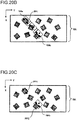
- Figs. 20A to 20D are explanatory diagrams illustrating a recognition process of parts PP that can be gripped by the two gripping mechanisms 164a and 164b.
- the image recognition unit 214 first recognizes a part PP1 that can be gripped by a first gripping mechanism 164a ( Fig. 20A ).
- the part PP1 is referred to as "first grippable part PP1".
- the image recognition unit 214 recognizes a position of a second gripping mechanism 164b in a state of gripping the first grippable part PP1 with the first gripping mechanism 164a ( Fig. 20B ) .
- the image recognition unit 214 calculates a coordinate and a gripping angle (angle around Z-axis) of the second gripping mechanism 164b using a positional relationship in the horizontal direction of the two gripping mechanisms 164a and 164b. Then, the image recognition unit 214 recognizes a part PP2 that can be gripped by the second gripping mechanism 164b ( Fig. 20C ).
- the part PP2 is referred to as "second grippable part PP2".
- the second grippable part PP2 it is preferable to select a part PP that is most easily gripped by the second gripping mechanism 164b in the state of gripping the first grippable part PP1 with the first gripping mechanism 164a.
- the selection can be performed, for example, according to a pick-up cost.
- the "pick-up cost" is calculated according to a predetermined calculation method with respect to one or more parts PP that can be gripped by the second gripping mechanism 164b in the state of gripping the first grippable part PP1 with the first gripping mechanism 164a.
- a trajectory of the robot 100 required for gripping one or more parts PP near the second gripping mechanism 164b by the second gripping mechanism 164b is calculated from the state ( Fig. 20A ) of gripping the first grippable part PP1 with the first gripping mechanism 164a, and a time for moving the trajectory is taken as the pick-up cost.
- a distance between the second gripping mechanism 164b and each part PP is calculated for one or more parts PP near the second gripping mechanism 164b from the state ( Fig. 20A ) of gripping the first grippable part PP1 with the first gripping mechanism 164a, and the distance is taken as the pick-up cost.
- a rotation angle (rotation angle of torsional joint J4) of the end effector 160c required for gripping one or more parts PP near the second gripping mechanism 164b by the second gripping mechanism 164b is calculated from the state ( Fig. 20A ) of gripping the first grippable part PP1 with the first gripping mechanism 164a, and the rotation angle is taken as the pick-up cost.
- the second grippable part PP2 illustrated in Fig. 20C is a part in which the pick-up cost calculated by the calculation method 2 is minimized.
- the second grippable part PP2 illustrated in Fig. 20D is a part in which the pick-up cost calculated by the calculation method 3 is minimized.
- the calculation method 1 trajectory reference
- the calculation method 3 rotation angle reference
- the calculation method 1 (trajectory reference) or the calculation method 2 (distance reference) is suitable.
- the pick-up cost is respectively calculated according to the predetermined calculation method with respect to one or more parts PP that can be gripped by the second gripping mechanism 164b in the state of gripping the first grippable part PP1 with the first gripping mechanism 164a, and the second grippable part PP2 is selected according to the pick-up costs, it is possible to improve the efficiency of gripping the part with the second gripping mechanism 164b.
- the selection of two grippable parts as described above can also be employed in a robot including an end effector having two pick-up mechanisms (for example, adsorption pick-up mechanisms) other than the gripping mechanism 164.
- the image recognition unit 214 executes a process of recognizing a second pickable part PP2 that can be picked up by a second pick-up mechanism in a state of holding a first pickable part PP1 with a first pick-up mechanism. In this manner, it is possible to improve the efficiency of picking up the part with the second pick-up mechanism.
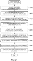
- Fig. 21 is a flowchart of an initial setting of control parameters of the part feeder 400
- Figs. 22A to 22E are explanatory diagrams illustrating process contents of steps S420 to S450 of Fig. 21 .
- the process is executed before performing the pick-up work of the part PP by the robot 100 described above.
- the process is executed by acquiring an image of parts PP in the part accommodating region 430 by the camera 430 and analyzing the image by the control parameter setting unit 215.
- step S410 a balance adjustment of vibration intensity of the plurality of vibration actuators 424 is performed.
- the adjustment is performed for compensating a tilt of the part accommodating region 412 and differences in characteristics of each vibration actuator 424.
- the plurality of parts PP are accommodated in the part accommodating region 412, the plurality of vibration actuators 424 are vibrated in the same phase, and a coordinate (XY coordinate) of each part PP is acquired.
- amplitude of a vibration signal supplied to each vibration actuator 424 is adjusted such that coordinates of the plurality of parts PP are not unevenly distributed and an average value of the coordinates positions at the center of the part accommodating region 412.
- the balance of the vibration intensity adjusted as described above is used also after step S420.
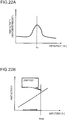
- step S420 a frequency that can activate the motion of the parts PP is measured.
- the vibration actuators 424 with the predetermined number are vibrated, and a movement amount of the part PP is acquired. Then, a frequency of the vibration signal that maximizes the movement amount of the part PP is adjusted.
- Fig. 22A illustrates an example of a relationship between the frequency and the part activity (movement amount of parts PP) in step S420.
- a frequency Fc at the peak of the graph is measured as the frequency that can activate the motion of the parts.
- the frequency Fc is, for example, a value equal to the resonance frequency of the part accommodating region 412.
- the appropriate frequency determined as described above is used also after step S430.
- the number of vibration actuators 424 used in step S420 a predetermined number of one or more can be used.
- the frequency that can activate the motion of the parts may be measured for each combination of the used number of the vibration actuator 424 and a used place thereof.
- the frequency that can activate the motion of the parts may be measured for each of phase difference values (for example, 0 degrees and 180 degrees) of the vibration actuators. In this manner, the point that it is preferable to set the appropriate control parameter for each combination of the used number of the vibration actuator 424 and the used place thereof is the same as other control parameters described below.
- step S430 amplitude that can prevent jump-out of the parts PP is measured.
- the amplitude is amplitude as large as possible within a limit in which the parts PP do not jump out of the part accommodating region 412.
- the plurality of vibration actuators 424 are vibrated, and it is determined from an image of the camera 430 whether the parts PP jump out of the part accommodating unit 410. The determination is performed while gradually increasing the amplitude of the vibration signal to obtain maximum amplitude at which the jump-out of the parts PP is not detected.
- Fig. 22B illustrates an example of a relationship between the amplitude in step S430 and the part activity.
- maximum amplitude Amax at which the jump-out of the parts PP is not detected is measured as amplitude that can prevent jump-out of the parts PP.
- the appropriate amplitude determined as described above is used also after step S440.
- step S440 the appropriate number of parts PP in the part feeder 400 is determined.
- a lot of parts PP are accommodated in the part accommodating region 412
- the separation operation ( Fig. 4B ) is performed, and then an image acquired by the camera 430 is analyzed to obtain the number of the parts PP that can be picked up. It is preferable to determine whether the picking up is possible by ignoring the front and back of the part PP. In this case, for example, a part PP which is not overlapped with another part PP at all is determined as the part that can be picked up.
- This process is executed respectively under conditions that the number of parts PP accommodated in the part accommodating region 412 is subsequently changed, and the number of parts when the number of parts that can be picked up is the maximum is determined as the appropriate number of parts in the part feeder 400.
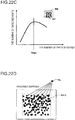
- Fig. 22C illustrates an example of a relationship between the number of parts in the part feeder 400 in step S440 and the number of parts detected as pickable.
- the number of parts in the part feeder 400 when the number of detected parts peaks is determined as the appropriate number of parts in the part feeder 400.
- the appropriate number of parts determined as described above is used also after step S450.
- a window PW may be provided around the part PP in consideration of portions gripped by the gripping mechanism 164 as illustrated in Fig. 22C , and a part PP in which the window PW thereof does not overlap with the outline of another part PP may be recognized as "part PP that can be picked up".
- the additional regions AD ( Fig. 13A ) described in the third embodiment may be used instead of the window PW.
- Fig. 22D is an explanatory diagram illustrating a process of determining the number of parts by simulation.
- one part is first imaged using the camera 430, and a part image Mp is cut out.
- an image in which the cut out part image Mp is disposed randomly in a region R412 having the same shape as the part accommodating region 412 is created by simulation.
- the number of parts that can be picked up is obtained by analyzing the simulation image.
- this process is executed a plurality of times while changing the number of part images Mp in the region R412, it is possible to obtain the same characteristics as those in Fig. 22C by simulation.
- step S450 control parameters of the separation command are adjusted.
- the adjustment process for example, the plurality of parts PP are accommodated in the part accommodating region 412, the separation operation ( Fig. 4B ) by the separation command is performed, and then an image acquired by the camera 430 is analyzed to obtain the number of the parts PP that can be picked up. It is preferable to determine whether the picking up is possible by ignoring the front and back of the part PP. It is preferable that the number of parts PP accommodated in the part accommodating region 412 is, for example, the appropriate number of parts determined in step S440. This process is executed respectively under conditions that the continuing time of the separation operation is subsequently changed, and a value in which the number of parts that can be picked up is sufficiently large and the continuing time of the separation operation is not excessively long is determined as the continuing time of the separation operation.
- Fig. 22E illustrates an example of a relationship between the continuing time of the separation operation in step S450 and the number of parts detected as pickable.
- results obtained in three cases where the number of parts in the part feeder 400 is 130, 65, and 33 are illustrated for reference.
- the detected number of parts PP that can be picked up increases as the continuing time of the separation operation increases, but saturates after reaching certain continuing times. Therefore, continuing times (times indicated by open circles in Fig. 22E ) in which the number of parts that can be picked up is sufficiently large and the continuing time of the separation operation is not excessively long are determined as the continuing time of the separation operation.
- the continuing time of the separation operation for example, as a time to reach a value obtained by multiplying a peak value of the number of parts that can be picked up by a predetermined coefficient K. It is preferable to set the coefficient K to a value of, for example, less than one and 0.9 or more.
- step S460 control parameters of the centering command to avoid the interference region Rint are adjusted.
- the interference region Rint is a region where the gripping mechanism 164 interferes with the outer peripheral wall 414 in the outer periphery portion of the part accommodating region 412 as described with reference to Fig. 12A in the third embodiment.
- the adjustment process for example, the plurality of parts PP are accommodated in the part accommodating region 412, the separation operation ( Fig. 4B ) is performed, and then the centering operation (step S225 of Fig. 11 and Fig. 12B ) for the interference region Rint is executed, and an image acquired by the camera 430 is analyzed to obtain the number of the parts PP that can be picked up.
- the number of parts PP accommodated in the part accommodating region 412 is, for example, the appropriate number of parts determined in step S440. This process is executed respectively under conditions that the continuing time of the centering operation is subsequently changed, and a continuing time during which the number of parts that can be picked up is sufficiently large and the continuing time of the centering operation is not excessively long is determined as the continuing time of the centering operation for avoiding the interference region.
- step S470 control parameters of the flip command are adjusted.
- the flip operation Fig. 4C
- an image acquired by the camera 430 is analyzed to determine whether the part PP is inverted.
- This process is executed respectively under conditions that the continuing time of the flip operation is subsequently changed, and a continuing time during which a probability of inverting the part PP is high and the continuing time of the flip operation is not excessively long is determined as the continuing time of the flip operation.
- step S480 control parameters of the feed command are adjusted.
- the adjustment process for example, the plurality of parts PP are accommodated in the part accommodating region 412, the feed operation ( Fig. 4A ) by the feed command is performed, and then an image acquired by the camera 430 is analyzed to determine the movement amounts of the parts PP.
- This process is executed respectively under conditions that the continuing time of the feed operation is subsequently changed, and a time during which the movement amounts of the parts PP are appropriate is determined as the continuing time of the feed operation.
- the continuing time of the feed operation may be determined by obtaining a movement speed [mm/sec] of the parts PP.
- the movement speed [mm/sec] of the parts PP for example, by accommodating the plurality of parts PP in the part accommodating region 412, performing the feed operation ( Fig. 4A ) by the feed command for a constant time (for example, one second), and then analyzing an image acquired by the camera 430. Then, it is possible to determine the continuing time of the feed operation by multiplying a distance to be moved by the movement speed.
- a part replenishment condition by the hopper 500 is determined.
- the hopper 500 is operated for a constant time to replenish the part PP to the part accommodating region 412 and an image acquired by the camera 430 is analyzed to obtain the number of replenished parts.
- This process is executed respectively under conditions that a replenishment time of the hopper 500 is subsequently changed, and a time during which the number of replenished parts PP is appropriate is determined as the replenishment time of the hopper 500.
- the number of replenished parts PP it is preferable to determine both the number of initial replenishments in step S200 of Fig. 6 and the number of replenishments after the second replenishment in step S170.
- the number of replenishments after the second replenishment may be set to the value of 1/ (N 412 - 1) of the number of initial replenishments.
- the part replenishment condition may be determined by obtaining a supply speed [pcs/sec] of the parts PP.
- the hopper 500 is operated for a constant time (for example, one second) to replenish the part PP to the part accommodating region 412 and an image acquired by the camera 430 is analyzed to obtain the number of replenished parts and the supply speed [pcs/sec] of the parts PP by the hopper 500. Then, it is possible to obtain the replenishment time of the hopper 500 by dividing the number of parts to be supplied by the supply speed.
- control command in which the part feeder control unit 212 transmits to the part feeder 400 is configured so as to include the control parameters relating to the plurality of vibration actuators 424 among the control parameters set in this manner.
- the part feeder control unit 212 selects one or more control commands from the plurality of control commands respectively including the control parameters of the plurality of vibration actuators 424 and transmits the selected control command to the part feeder 400 for causing the part feeder 400 to perform the operation according to the selected control command. Accordingly, it is possible to transmit the control parameters suitable for the operation of the part feeder 400 to the part feeder 400.
- the invention is not limited to the embodiments, the examples, and the modification examples described above, and can be realized in various configurations without departing from the spirit of the invention.
- the technical features in the embodiments, the examples, and the modification examples corresponding to the technical features in each aspect described in the summary section can be replaced or combined as appropriate in order to solve part or all of the problems described above, or to achieve part or all of the effects described above.
- the technical feature is not described as an essential feature in this specification, the feature can be deleted as appropriate.
Landscapes
- Engineering & Computer Science (AREA)
- Mechanical Engineering (AREA)
- Robotics (AREA)
- Physics & Mathematics (AREA)
- General Physics & Mathematics (AREA)
- Automation & Control Theory (AREA)
- General Engineering & Computer Science (AREA)
- Manufacturing & Machinery (AREA)
- Quality & Reliability (AREA)
- Human Computer Interaction (AREA)
- Manipulator (AREA)
Priority Applications (1)
| Application Number | Priority Date | Filing Date | Title |
|---|---|---|---|
| EP23165668.7A EP4223462A1 (de) | 2017-06-06 | 2018-06-05 | Steuerungsvorrichtung eines robotersystems und robotersystem |
Applications Claiming Priority (2)
| Application Number | Priority Date | Filing Date | Title |
|---|---|---|---|
| JP2017111275 | 2017-06-06 | ||
| JP2017214446A JP6992415B2 (ja) | 2017-06-06 | 2017-11-07 | ロボットシステムの制御装置及びロボットシステム |
Related Child Applications (1)
| Application Number | Title | Priority Date | Filing Date |
|---|---|---|---|
| EP23165668.7A Division EP4223462A1 (de) | 2017-06-06 | 2018-06-05 | Steuerungsvorrichtung eines robotersystems und robotersystem |
Publications (2)
| Publication Number | Publication Date |
|---|---|
| EP3412414A2 true EP3412414A2 (de) | 2018-12-12 |
| EP3412414A3 EP3412414A3 (de) | 2018-12-26 |
Family
ID=62567329
Family Applications (2)
| Application Number | Title | Priority Date | Filing Date |
|---|---|---|---|
| EP18175990.3A Ceased EP3412414A3 (de) | 2017-06-06 | 2018-06-05 | Steuerungssystem eines robotersystems sowie robotersystem |
| EP23165668.7A Pending EP4223462A1 (de) | 2017-06-06 | 2018-06-05 | Steuerungsvorrichtung eines robotersystems und robotersystem |
Family Applications After (1)
| Application Number | Title | Priority Date | Filing Date |
|---|---|---|---|
| EP23165668.7A Pending EP4223462A1 (de) | 2017-06-06 | 2018-06-05 | Steuerungsvorrichtung eines robotersystems und robotersystem |
Country Status (3)
| Country | Link |
|---|---|
| US (2) | US10894316B2 (de) |
| EP (2) | EP3412414A3 (de) |
| CN (2) | CN118305806A (de) |
Cited By (2)
| Publication number | Priority date | Publication date | Assignee | Title |
|---|---|---|---|---|
| WO2024166454A1 (en) * | 2023-02-07 | 2024-08-15 | Mitsubishi Electric Corporation | Systems and methods for object orientation and manipulation via machine learning based control |
| EP4382246A4 (de) * | 2021-08-06 | 2025-02-19 | Fuji Corporation | Werkstückaufnahmeverfahren und werkstückaufnahmesystem |
Families Citing this family (9)
| Publication number | Priority date | Publication date | Assignee | Title |
|---|---|---|---|---|
| CN109746914B (zh) * | 2018-12-29 | 2021-05-04 | 深圳镁伽科技有限公司 | 构建机器人的方法、机器人控制设备、系统及存储介质 |
| JP2020193098A (ja) * | 2019-05-30 | 2020-12-03 | セイコーエプソン株式会社 | 供給装置およびロボットシステム |
| JP2020199625A (ja) * | 2019-06-13 | 2020-12-17 | ファナック株式会社 | シミュレーション装置 |
| CN110480294A (zh) * | 2019-07-25 | 2019-11-22 | 无锡丹尼克尔自动化科技有限公司 | 一种批量散装零部件分离装置、上料系统和上料方法 |
| CN111301951A (zh) * | 2020-03-06 | 2020-06-19 | 厦门沃珑自动化设备有限公司 | 一种柔性上料方法 |
| WO2022013935A1 (ja) * | 2020-07-14 | 2022-01-20 | 株式会社Fuji | ロボットシステム |
| CN114148703B (zh) * | 2020-09-08 | 2024-07-19 | 爱来音科技有限公司 | 工件姿势控制装置、工件供给系统以及工件姿势控制方法 |
| CN113172621B (zh) * | 2021-04-13 | 2023-05-09 | 哈尔滨工业大学(威海) | 一种面向scara机械臂的动力学参数辨识方法 |
| EP4574348A1 (de) * | 2023-12-22 | 2025-06-25 | Vibrotech S.r.l. | Verfahren zur neupositionierung einer gruppe von auf einem ständer in loser form angeordneten objekten |
Citations (1)
| Publication number | Priority date | Publication date | Assignee | Title |
|---|---|---|---|---|
| JPS60200385A (ja) | 1984-03-26 | 1985-10-09 | Hitachi Ltd | 姿勢判定方式 |
Family Cites Families (21)
| Publication number | Priority date | Publication date | Assignee | Title |
|---|---|---|---|---|
| JPS645742A (en) | 1987-06-26 | 1989-01-10 | Matsushita Electric Industrial Co Ltd | Flexible parts supplying device |
| US5489019A (en) * | 1994-08-04 | 1996-02-06 | Stokes-Merrill Corporation | Feed tray for singularizing objects |
| US6056108A (en) * | 1997-11-17 | 2000-05-02 | Adept Technology, Inc. | Impulse-based, flexible parts feeder |
| JP3876260B2 (ja) * | 2004-09-16 | 2007-01-31 | ファナック株式会社 | 物品供給装置 |
| US7313464B1 (en) * | 2006-09-05 | 2007-12-25 | Adept Technology Inc. | Bin-picking system for randomly positioned objects |
| US20100063629A1 (en) * | 2008-09-10 | 2010-03-11 | Rixan Associates, Inc. | System and method for recirculating parts |
| CH700371B1 (fr) * | 2009-02-05 | 2013-11-15 | Asyril Sa | Système d'alimentation en composants. |
| JP5500926B2 (ja) * | 2009-09-29 | 2014-05-21 | キヤノン株式会社 | 物体把持制御方法及び装置 |
| JP5402697B2 (ja) * | 2009-10-26 | 2014-01-29 | 株式会社安川電機 | ロボット装置及びワーク取り出しシステム並びにワーク取り出し方法 |
| KR101968460B1 (ko) * | 2011-07-08 | 2019-04-11 | 신포니아 테크놀로지 가부시끼가이샤 | 진동 장치, 물품 반송 장치 및 물품 분별 장치 |
| CN203003902U (zh) * | 2012-12-29 | 2013-06-19 | 深圳众为兴技术股份有限公司 | 万能机械手爪 |
| US9669432B2 (en) * | 2013-08-27 | 2017-06-06 | Te Connectivity Corporation | Component feeding system |
| JP2015147256A (ja) * | 2014-02-04 | 2015-08-20 | セイコーエプソン株式会社 | ロボット、ロボットシステム、制御装置、及び制御方法 |
| JP6726934B2 (ja) * | 2015-04-24 | 2020-07-22 | シンフォニアテクノロジー株式会社 | 振込装置 |
| EP3383593B1 (de) * | 2015-12-03 | 2021-04-28 | ABB Schweiz AG | Anlernen eines industrieroboters zum greifen von teilen |
| CN105619414B (zh) * | 2016-04-09 | 2017-07-07 | 浙江智昌实业有限公司 | 一种程控机器人系统 |
| JP6592043B2 (ja) * | 2017-07-19 | 2019-10-16 | ファナック株式会社 | ワークを循環する供給装置を備える搬送装置 |
| US10974908B2 (en) * | 2017-09-12 | 2021-04-13 | Spirol International Corporation | Methods and systems for controlling a vibratory feeder |
| US10926962B2 (en) * | 2019-03-07 | 2021-02-23 | Raytheon Company | Flexible feeding tray and system for singulating bulk objects |
| JP7140037B2 (ja) * | 2019-04-15 | 2022-09-21 | トヨタ自動車株式会社 | 車両遠隔指示システム |
| JP2020193098A (ja) * | 2019-05-30 | 2020-12-03 | セイコーエプソン株式会社 | 供給装置およびロボットシステム |
-
2018
- 2018-06-05 EP EP18175990.3A patent/EP3412414A3/de not_active Ceased
- 2018-06-05 CN CN202410604616.3A patent/CN118305806A/zh active Pending
- 2018-06-05 EP EP23165668.7A patent/EP4223462A1/de active Pending
- 2018-06-05 CN CN201810567589.1A patent/CN108994829A/zh active Pending
- 2018-06-05 US US16/000,084 patent/US10894316B2/en not_active Ceased
-
2022
- 2022-12-29 US US18/090,599 patent/USRE50190E1/en active Active
Patent Citations (1)
| Publication number | Priority date | Publication date | Assignee | Title |
|---|---|---|---|---|
| JPS60200385A (ja) | 1984-03-26 | 1985-10-09 | Hitachi Ltd | 姿勢判定方式 |
Non-Patent Citations (1)
| Title |
|---|
| CLAUDIA RALUCA TUDORIE ED - LEE SEONG-WHAN ET AL: "Different Approaches in Feeding of a Flexible Manufacturing Cell", 1 January 2010, ADVANCES IN BIOMETRICS : INTERNATIONAL CONFERENCE, ICB 2007, SEOUL, KOREA, AUGUST 27 - 29, 2007 ; PROCEEDINGS; [LECTURE NOTES IN COMPUTER SCIENCE; LECT.NOTES COMPUTER], SPRINGER, BERLIN, HEIDELBERG, PAGE(S) 509 - 520, ISBN: 978-3-540-74549-5, XP047426840 * |
Cited By (2)
| Publication number | Priority date | Publication date | Assignee | Title |
|---|---|---|---|---|
| EP4382246A4 (de) * | 2021-08-06 | 2025-02-19 | Fuji Corporation | Werkstückaufnahmeverfahren und werkstückaufnahmesystem |
| WO2024166454A1 (en) * | 2023-02-07 | 2024-08-15 | Mitsubishi Electric Corporation | Systems and methods for object orientation and manipulation via machine learning based control |
Also Published As
| Publication number | Publication date |
|---|---|
| CN108994829A (zh) | 2018-12-14 |
| CN118305806A (zh) | 2024-07-09 |
| US10894316B2 (en) | 2021-01-19 |
| EP4223462A1 (de) | 2023-08-09 |
| EP3412414A3 (de) | 2018-12-26 |
| US20180345500A1 (en) | 2018-12-06 |
| USRE50190E1 (en) | 2024-10-29 |
Similar Documents
| Publication | Publication Date | Title |
|---|---|---|
| EP3412414A2 (de) | Steuerungssystem eines robotersystems sowie robotersystem | |
| JP6992415B2 (ja) | ロボットシステムの制御装置及びロボットシステム | |
| JP6057862B2 (ja) | 部品供給装置および部品供給装置のプログラム生成方法 | |
| JP6744709B2 (ja) | 情報処理装置、情報処理方法 | |
| US9604365B2 (en) | Device and method of transferring articles by using robot | |
| JP7233858B2 (ja) | ロボット制御装置、ロボット制御方法、及びロボット制御プログラム | |
| CN110355754A (zh) | 机器人手眼系统、控制方法、设备及存储介质 | |
| JP2012030320A (ja) | 作業システム、作業ロボット制御装置および作業プログラム | |
| CN114348639A (zh) | 用于多分区吸盘的物体抓取方法、装置、设备和介质 | |
| CN118617182A (zh) | 显示装置、机床及液体的放出方法 | |
| JP2020196058A (ja) | ロボットシステムおよびロボットシステムの制御方法 | |
| WO2019098074A1 (ja) | 線状物把持方法および制御装置 | |
| CN114901441A (zh) | 机器人系统的控制装置、机器人系统的控制方法、计算机控制程序及机器人系统 | |
| JP2000263482A (ja) | ワークの姿勢探索方法および姿勢探索装置ならびにロボットによるワーク把持方法およびワーク把持装置 | |
| JP4643425B2 (ja) | 部品実装順序決定方法 | |
| JP5794856B2 (ja) | 電子部品装着装置、および、電子部品装着方法 | |
| JP2022076656A (ja) | ロボットプログラム、ワーク拾い上げ方法、制御装置およびロボットシステム | |
| JPH0797059A (ja) | 物体取出装置 | |
| EP4491353A1 (de) | Robotersteuerungsvorrichtung und robotersteuerungsverfahren | |
| JP7460744B1 (ja) | ロボット制御装置、ロボット、かき混ぜ方法及びプログラム | |
| TW202408758A (zh) | 程式生成裝置、控制裝置及程式 | |
| CN115922668B (zh) | 示教方法 | |
| JP6552221B2 (ja) | 情報処理装置、情報処理方法 | |
| JP2001105361A (ja) | ピッキングシステム | |
| JP2024018507A (ja) | 検査装置および視野角検査方法 |
Legal Events
| Date | Code | Title | Description |
|---|---|---|---|
| PUAI | Public reference made under article 153(3) epc to a published international application that has entered the european phase |
Free format text: ORIGINAL CODE: 0009012 |
|
| STAA | Information on the status of an ep patent application or granted ep patent |
Free format text: STATUS: THE APPLICATION HAS BEEN PUBLISHED |
|
| REG | Reference to a national code |
Ref country code: DE Ref legal event code: R079 Free format text: PREVIOUS MAIN CLASS: B25J0009160000 Ipc: B25J0009000000 |
|
| PUAL | Search report despatched |
Free format text: ORIGINAL CODE: 0009013 |
|
| AK | Designated contracting states |
Kind code of ref document: A2 Designated state(s): AL AT BE BG CH CY CZ DE DK EE ES FI FR GB GR HR HU IE IS IT LI LT LU LV MC MK MT NL NO PL PT RO RS SE SI SK SM TR |
|
| AX | Request for extension of the european patent |
Extension state: BA ME |
|
| AK | Designated contracting states |
Kind code of ref document: A3 Designated state(s): AL AT BE BG CH CY CZ DE DK EE ES FI FR GB GR HR HU IE IS IT LI LT LU LV MC MK MT NL NO PL PT RO RS SE SI SK SM TR |
|
| AX | Request for extension of the european patent |
Extension state: BA ME |
|
| RIC1 | Information provided on ipc code assigned before grant |
Ipc: B25J 9/16 20060101ALI20181119BHEP Ipc: G05B 19/418 20060101ALI20181119BHEP Ipc: B65G 27/16 20060101ALI20181119BHEP Ipc: B25J 9/00 20060101AFI20181119BHEP |
|
| STAA | Information on the status of an ep patent application or granted ep patent |
Free format text: STATUS: REQUEST FOR EXAMINATION WAS MADE |
|
| 17P | Request for examination filed |
Effective date: 20190325 |
|
| RBV | Designated contracting states (corrected) |
Designated state(s): AL AT BE BG CH CY CZ DE DK EE ES FI FR GB GR HR HU IE IS IT LI LT LU LV MC MK MT NL NO PL PT RO RS SE SI SK SM TR |
|
| STAA | Information on the status of an ep patent application or granted ep patent |
Free format text: STATUS: EXAMINATION IS IN PROGRESS |
|
| 17Q | First examination report despatched |
Effective date: 20210311 |
|
| STAA | Information on the status of an ep patent application or granted ep patent |
Free format text: STATUS: THE APPLICATION HAS BEEN REFUSED |
|
| 18R | Application refused |
Effective date: 20230222 |