EP3409972A1 - Unter druck stehendes, teleskopisches bein einer vordergabel, vordergabel und fahrzeug - Google Patents
Unter druck stehendes, teleskopisches bein einer vordergabel, vordergabel und fahrzeug Download PDFInfo
- Publication number
- EP3409972A1 EP3409972A1 EP17173880.0A EP17173880A EP3409972A1 EP 3409972 A1 EP3409972 A1 EP 3409972A1 EP 17173880 A EP17173880 A EP 17173880A EP 3409972 A1 EP3409972 A1 EP 3409972A1
- Authority
- EP
- European Patent Office
- Prior art keywords
- fluid
- leg
- damping
- fork leg
- telescopic fork
- Prior art date
- Legal status (The legal status is an assumption and is not a legal conclusion. Google has not performed a legal analysis and makes no representation as to the accuracy of the status listed.)
- Withdrawn
Links
Images


Classifications
-
- F—MECHANICAL ENGINEERING; LIGHTING; HEATING; WEAPONS; BLASTING
- F16—ENGINEERING ELEMENTS AND UNITS; GENERAL MEASURES FOR PRODUCING AND MAINTAINING EFFECTIVE FUNCTIONING OF MACHINES OR INSTALLATIONS; THERMAL INSULATION IN GENERAL
- F16F—SPRINGS; SHOCK-ABSORBERS; MEANS FOR DAMPING VIBRATION
- F16F9/00—Springs, vibration-dampers, shock-absorbers, or similarly-constructed movement-dampers using a fluid or the equivalent as damping medium
- F16F9/06—Springs, vibration-dampers, shock-absorbers, or similarly-constructed movement-dampers using a fluid or the equivalent as damping medium using both gas and liquid
- F16F9/066—Units characterised by the partition, baffle or like element
- F16F9/067—Partitions of the piston type, e.g. sliding pistons
-
- B—PERFORMING OPERATIONS; TRANSPORTING
- B62—LAND VEHICLES FOR TRAVELLING OTHERWISE THAN ON RAILS
- B62K—CYCLES; CYCLE FRAMES; CYCLE STEERING DEVICES; RIDER-OPERATED TERMINAL CONTROLS SPECIALLY ADAPTED FOR CYCLES; CYCLE AXLE SUSPENSIONS; CYCLE SIDE-CARS, FORECARS, OR THE LIKE
- B62K25/00—Axle suspensions
- B62K25/04—Axle suspensions for mounting axles resiliently on cycle frame or fork
- B62K25/06—Axle suspensions for mounting axles resiliently on cycle frame or fork with telescopic fork, e.g. including auxiliary rocking arms
- B62K25/08—Axle suspensions for mounting axles resiliently on cycle frame or fork with telescopic fork, e.g. including auxiliary rocking arms for front wheel
-
- F—MECHANICAL ENGINEERING; LIGHTING; HEATING; WEAPONS; BLASTING
- F16—ENGINEERING ELEMENTS AND UNITS; GENERAL MEASURES FOR PRODUCING AND MAINTAINING EFFECTIVE FUNCTIONING OF MACHINES OR INSTALLATIONS; THERMAL INSULATION IN GENERAL
- F16F—SPRINGS; SHOCK-ABSORBERS; MEANS FOR DAMPING VIBRATION
- F16F9/00—Springs, vibration-dampers, shock-absorbers, or similarly-constructed movement-dampers using a fluid or the equivalent as damping medium
- F16F9/06—Springs, vibration-dampers, shock-absorbers, or similarly-constructed movement-dampers using a fluid or the equivalent as damping medium using both gas and liquid
- F16F9/062—Bi-tubular units
-
- F—MECHANICAL ENGINEERING; LIGHTING; HEATING; WEAPONS; BLASTING
- F16—ENGINEERING ELEMENTS AND UNITS; GENERAL MEASURES FOR PRODUCING AND MAINTAINING EFFECTIVE FUNCTIONING OF MACHINES OR INSTALLATIONS; THERMAL INSULATION IN GENERAL
- F16F—SPRINGS; SHOCK-ABSORBERS; MEANS FOR DAMPING VIBRATION
- F16F9/00—Springs, vibration-dampers, shock-absorbers, or similarly-constructed movement-dampers using a fluid or the equivalent as damping medium
- F16F9/06—Springs, vibration-dampers, shock-absorbers, or similarly-constructed movement-dampers using a fluid or the equivalent as damping medium using both gas and liquid
- F16F9/064—Units characterised by the location or shape of the expansion chamber
- F16F9/065—Expansion chamber provided on the upper or lower end of a damper, separately there from or laterally on the damper
-
- F—MECHANICAL ENGINEERING; LIGHTING; HEATING; WEAPONS; BLASTING
- F16—ENGINEERING ELEMENTS AND UNITS; GENERAL MEASURES FOR PRODUCING AND MAINTAINING EFFECTIVE FUNCTIONING OF MACHINES OR INSTALLATIONS; THERMAL INSULATION IN GENERAL
- F16F—SPRINGS; SHOCK-ABSORBERS; MEANS FOR DAMPING VIBRATION
- F16F9/00—Springs, vibration-dampers, shock-absorbers, or similarly-constructed movement-dampers using a fluid or the equivalent as damping medium
- F16F9/06—Springs, vibration-dampers, shock-absorbers, or similarly-constructed movement-dampers using a fluid or the equivalent as damping medium using both gas and liquid
- F16F9/066—Units characterised by the partition, baffle or like element
-
- F—MECHANICAL ENGINEERING; LIGHTING; HEATING; WEAPONS; BLASTING
- F16—ENGINEERING ELEMENTS AND UNITS; GENERAL MEASURES FOR PRODUCING AND MAINTAINING EFFECTIVE FUNCTIONING OF MACHINES OR INSTALLATIONS; THERMAL INSULATION IN GENERAL
- F16F—SPRINGS; SHOCK-ABSORBERS; MEANS FOR DAMPING VIBRATION
- F16F9/00—Springs, vibration-dampers, shock-absorbers, or similarly-constructed movement-dampers using a fluid or the equivalent as damping medium
- F16F9/32—Details
- F16F9/36—Special sealings, including sealings or guides for piston-rods
- F16F9/368—Sealings in pistons
-
- F—MECHANICAL ENGINEERING; LIGHTING; HEATING; WEAPONS; BLASTING
- F16—ENGINEERING ELEMENTS AND UNITS; GENERAL MEASURES FOR PRODUCING AND MAINTAINING EFFECTIVE FUNCTIONING OF MACHINES OR INSTALLATIONS; THERMAL INSULATION IN GENERAL
- F16F—SPRINGS; SHOCK-ABSORBERS; MEANS FOR DAMPING VIBRATION
- F16F9/00—Springs, vibration-dampers, shock-absorbers, or similarly-constructed movement-dampers using a fluid or the equivalent as damping medium
- F16F9/32—Details
- F16F9/50—Special means providing automatic damping adjustment, i.e. self-adjustment of damping by particular sliding movements of a valve element, other than flexions or displacement of valve discs; Special means providing self-adjustment of spring characteristics
- F16F9/512—Means responsive to load action, i.e. static load on the damper or dynamic fluid pressure changes in the damper, e.g. due to changes in velocity
-
- F—MECHANICAL ENGINEERING; LIGHTING; HEATING; WEAPONS; BLASTING
- F16—ENGINEERING ELEMENTS AND UNITS; GENERAL MEASURES FOR PRODUCING AND MAINTAINING EFFECTIVE FUNCTIONING OF MACHINES OR INSTALLATIONS; THERMAL INSULATION IN GENERAL
- F16F—SPRINGS; SHOCK-ABSORBERS; MEANS FOR DAMPING VIBRATION
- F16F9/00—Springs, vibration-dampers, shock-absorbers, or similarly-constructed movement-dampers using a fluid or the equivalent as damping medium
- F16F9/32—Details
- F16F9/50—Special means providing automatic damping adjustment, i.e. self-adjustment of damping by particular sliding movements of a valve element, other than flexions or displacement of valve discs; Special means providing self-adjustment of spring characteristics
- F16F9/516—Special means providing automatic damping adjustment, i.e. self-adjustment of damping by particular sliding movements of a valve element, other than flexions or displacement of valve discs; Special means providing self-adjustment of spring characteristics resulting in the damping effects during contraction being different from the damping effects during extension, i.e. responsive to the direction of movement
-
- F—MECHANICAL ENGINEERING; LIGHTING; HEATING; WEAPONS; BLASTING
- F16—ENGINEERING ELEMENTS AND UNITS; GENERAL MEASURES FOR PRODUCING AND MAINTAINING EFFECTIVE FUNCTIONING OF MACHINES OR INSTALLATIONS; THERMAL INSULATION IN GENERAL
- F16F—SPRINGS; SHOCK-ABSORBERS; MEANS FOR DAMPING VIBRATION
- F16F2222/00—Special physical effects, e.g. nature of damping effects
- F16F2222/12—Fluid damping
-
- F—MECHANICAL ENGINEERING; LIGHTING; HEATING; WEAPONS; BLASTING
- F16—ENGINEERING ELEMENTS AND UNITS; GENERAL MEASURES FOR PRODUCING AND MAINTAINING EFFECTIVE FUNCTIONING OF MACHINES OR INSTALLATIONS; THERMAL INSULATION IN GENERAL
- F16F—SPRINGS; SHOCK-ABSORBERS; MEANS FOR DAMPING VIBRATION
- F16F2228/00—Functional characteristics, e.g. variability, frequency-dependence
- F16F2228/06—Stiffness
- F16F2228/066—Variable stiffness
-
- F—MECHANICAL ENGINEERING; LIGHTING; HEATING; WEAPONS; BLASTING
- F16—ENGINEERING ELEMENTS AND UNITS; GENERAL MEASURES FOR PRODUCING AND MAINTAINING EFFECTIVE FUNCTIONING OF MACHINES OR INSTALLATIONS; THERMAL INSULATION IN GENERAL
- F16F—SPRINGS; SHOCK-ABSORBERS; MEANS FOR DAMPING VIBRATION
- F16F2232/00—Nature of movement
- F16F2232/08—Linear
Definitions
- the present specification generally relates to the field of front fork for vehicles and in particularly discloses a pressurized front fork leg.
- a conventional shock absorber normally comprises a working cylinder filled with a damping fluid, such as hydraulic oil or gas, and a piston arranged on a piston rod movably arranged in the cylinder.
- the piston is further commonly arranged to divide the cylinder into a first and second working chamber and moves in the cylinder against the resistance of the fluid, which in turn causes damping fluid to move in the damping cylinder.
- shock absorber may be arranged between the vehicle chassis and the wheel to move telescopically as the vehicle travels along such that the movement of the wheel and vehicle is thus damped by the piston moving in the cylinder against the resistance of the fluid.
- shock absorbers may be arranged in a front fork arrangement and/or between the rider and the rear part of the motorcycle or bicycle, in either case damping impacts and vibrations with respect to the rider.
- the damping fluid may be pressurized with a compressing pressure.
- pressurized front forks have a tendency to increase in size and become rather expensive.
- the pressurizing function of the front fork may be achieved by a pressurizing piston arranged coaxially inside a damping fork leg fluidly connected with a fluid reservoir for holding pressurized fluid arranged outside said damping leg, so that said fluid reservoir, at least partly, may axially overlap the fork leg.
- a pressurized fork leg is provided that is both less expensive and smaller than prior art.
- having the pressurizing piston arranged inside the front fork leg in a damping system with damping oil has led to the surprising effect that undesired hysteresis is decreased since less damping oil may be used.
- the decrease of undesired hysteresis is partly due to that all damping oil comprise some air/gas in it and also that the oil is not traveling in channels outside of the fork leg, since that may contribute to undesired hysteresis.
- a telescopic fork leg for a front fork of a vehicle comprising an outer tube and an inner tube being telescopically arranged relative each other, and a main piston arrangement arranged in the inner tube configured to regulate a damping fluid for damping movements between two parts of the vehicle when in use.
- the telescopic fork leg comprises a pressurizing piston arranged in the inner tube and configured to pressurize the damping fluid, the pressurizing piston comprising an axial first end portion facing the main piston arrangement, and further comprising an axial opposite second end portion facing a pressurized volume.
- the telescopic fork leg comprises a fluid reservoir for holding a pressurized fluid, the fluid reservoir being fluidly coupled to the pressurized volume.
- the pressurizing piston is coaxially arranged with the main piston arrangement, inside the inner tube and the fluid reservoir is at least partly arranged on an outside of the inner tube.
- a pressurized fork leg is provided that is both less expensive, is smaller than prior solutions and has decreased levels of undesired hysteresis since less damping oil may be used.
- pressurizing piston in the context of the application “fluidly coupled” should be understood as any coupling means such as a channel, pipe, hose or other fluid connection means.
- the wording that the pressurizing piston is "arranged, Table inside said inner tube” comprise the different embodiments where the pressurizing piston may be arranged directly or indirectly in the inner tube, by being arranged inside one (or several) other components located inside the inner tube.
- the pressurizing piston is arranged inside the inner tube instead of in the fluid reservoir, the dimensions of the fluid reservoir may be created with less accuracy, since there is no piston moving inside said fluid reservoir.
- the fluid reservoir is arranged in a fork leg bottom body.
- the fluid reservoir is an aperture in the for leg bottom body.
- the aperture is a bore, drilled into said log bottom body.
- the pressurizing piston comprises a first sealing means configured to seal against the damping fluid, and a second sealing means configured to seal against the pressurized fluid, wherein the first and second sealing means are axially displaced along the axial extension of the pressurizing piston.
- the pressurizing piston may seal with adapted seals at the respective ends, and any pressurized fluid leaking through the respective seal may be handled between the seals.
- the pressurizing piston may act as a separating piston for separating the gas from the liquid.
- the damping fluid is a liquid such as damping oil
- the pressurized fluid is a gas, such as air, nitrogen, CO2.
- the pressurizing piston is axially pressure relived.
- the pressure from the gas side and pressure of the damping fluid relieves each other.
- the telescopic fork leg may further comprise a cylinder case arranged inside the inner tube, wherein the pressurizing piston is arranged inside the cylinder case.
- the cylinder case and inner tube may define an ambient volume for holding damping fluid.
- the telescopic fork leg further comprises a fluid coupling between the damping fluid and an ambient volume.
- the damping fluid may flow into the ambient volume.
- the fluid coupling between the damping fluid and an ambient volume is enabled by an aperture in the cylinder case axially located between the first sealing means and the second sealing means.
- any liquid or gas leaked through the respective seals may flow out to the ambient volume.
- the first sealing of the pressurizing piston is configured interact with the aperture in the cylinder case so that the fluid coupling between the damping fluid and an ambient volume is only opened when the pressurizing piston is in a predetermined axial position.
- the coupling between the damping fluid and an ambient volume may be closed by means of the first sealing means in ordinary use, but when the volume with damping fluid is increased so much that the axial position of the preloading piston reaches the predetermined axial position, the damping fluid is let out through the aperture in the cylinder case to the ambient volume.
- the telescopic fork leg further comprises an intermediate restriction means arranged between the main piston and the pressurizing piston, and configured to restrict the axial movement of the pressurizing piston.
- the intermediate restriction may restrict the axial movement of the pressurizing piston if something fails in the damper.
- the restriction means is further configured to restrict the fluid flow at high stroke speeds.
- the pressurizing piston may be prevented to move as the check valve maximum flow capacity is reached so that the check valve constitute a restriction for the flow.
- high stroke speeds may be e.g. 2-6 m/s, or 3-5 m/s.
- the main piston arrangement comprises a shim stack and a check valve for controlling the flow a damping fluid.
- the damping fluid flow may be controlled at the piston arrangement.
- the telescopic fork leg is one of a compression leg and a rebound leg, configured to mainly damp movements in the compression stroke or the rebound stroke, respectively.
- the piston comprises an electrically controlled valve for controlling the flow of damping medium.
- the electrically controlled valve comprises a spool at least partly having the shape of a hollow cylinder, the cylinder comprising a first fluid opening and a second fluid opening such that a flow of fluid is allowed to flow through the hollow cylinder from the inlet to the outlet via the first and second fluid opening.
- a front fork for a vehicle comprising two telescopic fork legs according to any one the embodiments above.
- one of the two telescopic fork legs is a compression leg configured to mainly damp movements in the compression stroke
- the other one of the two telescopic fork legs is a rebound leg configured to mainly damp movements in the rebound stroke.
- a vehicle comprising a front fork according to any of the embodiments described above.
- the main piston arrangement comprises a main piston and a main piston rod coupled to the main piston.
- the main piston being configured to regulate a damping fluid moving between a first chamber and a second chamber.
- the fork legs in the illustration are illustrated as having a first leg for compression damping and a second leg for rebound damping, the invention is equally applicable when the legs are designed to damp both rebound and compression movements in a single leg.
- the pressurizing piston may be arranged directly in the inner tube 102 or indirectly by being arranged inside one (or several) other components located inside the inner tube 102.
- the embodiment where the pressurizing piston is arranged directly in the inner tube would be a monotube fork leg. In such an embodiment the ambient volume 170 could be on the outside of the inner tube.
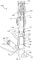
- FIG 1 a and 1 b are included to illustrate an overview of a front fork leg 100a from an outside view, and in a cross-section along the line "B-B" in fig 1 a.
- the front fork leg 100a is a compression leg, and is illustrated in further detail in figure 1 c.
- the compression front fork leg 100a comprise a main piston arrangement 120 for regulating the damping fluid. Further, it comprises the pressurizing piston 130, which at a first end face that damping fluid (upwards in the figure) and at the other ends face a pressurizing gas which is fluidly connected to a fluid reservoir 150.
- the fluid reservoir is arranged in the fork leg bottom body 160.
- the compression front fork leg 100a is now further discussed in relation to the close-up in fig. 1c .
- all the components as discussed above in relation to fig 1b are also present, and in addition more details are illustrated.
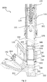
- the components in the rebound front fork 100b illustrated in fig. 2 comprise most of the components described in relation to fig 1c .
- the fork leg bottom comprises an aperture 161 for fitting a wheel axle of a front wheel of a vehicle.
- the front wheel axle may be fastened by a fastening arrangement 162.
- the fluid reservoir 150 arranged in the fork leg bottom body 160 comprise a fluid connection 151 to the inside of the inner tube 102.
- the fluid connection 151 connects the fluid reservoir with the cylinder case (103).
- the fluid connection may be achieved in any way but is illustrated as two bores, drilled from two directions, one from the cylinder case side and one from the fluid reservoir side.
- the fluid reservoir 150 comprises an end cap 152 and in the end cap there is a valve 153 for filling the fluid reservoir to a desired pressure.
- the fluid reservoir is a bore into the fork leg bottom body 160.
- the pressurizing piston 130 it is arranged in a cylinder case 103 which in turn is arranged in an inner tube 102.
- the pressurizing piston is configured to pressurize the damping fluid, whereby it comprises an axial first end portion 131 facing the main piston arrangement 120 (upwards in the figure), and further comprising an axial opposite second end portion 132 which is facing the pressurized volume being fluidly connected to the fluid reservoir 150.
- the pressurizing piston 130 comprise a first sealing means 133 which is configured to seal against the damping fluid. It also comprises a second sealing means 134 which is configured to seal against the pressurized fluid. Further, the first and second sealing means are axially displaced along the axial extension of the pressurizing piston 130, so that the first sealing means 133 is arranged on/close to the first end portion 131, and the second sealing means 134 is arranged on/close to the second end portion 132.
- the cylinder case 103 comprises an aperture 104 being axially located between said first sealing means 133 and said second sealing means 134 under normal use.
- the aperture allows a fluid coupling between the damping fluid and an ambient volume 170.
- the first sealing 133 of the pressurizing piston is further sized and adapted to interact with the aperture 104 in the cylinder case 103 so that the fluid coupling between the damping fluid and an ambient volume 170 is only open when the pressurizing piston 130 is in a predetermined axial position.
- the predetermined axial position being closer to the fork leg bottom 160 than under normal use.
- the damping medium may escape into the ambient volume 170 instead of pushing the pressurized piston further towards the fork leg bottom. This makes the system self-adjusting in terms of oil/damping medium levels.
- the aperture may be closed by means of the first sealing means 133 during ordinary use, but when the volume with damping fluid is increased so much that the axial position of the preloading piston reaches the predetermined axial position, the damping fluid is let out through the aperture 104 in the cylinder case 103 to the ambient volume 170.
- the fork leg comprise an intermediate restriction means 140 arranged between the main piston and the pressurizing piston.
- the compression leg comprises an end lock portion 123 forming an end so that pressure in compression stroke is built up between the main piston 121 and the end-lock 123.
- the fork leg comprises a main piston arrangement 120 as discussed above.
- the piston arrangement comprises a main piston 121 having a shim stack and a check valve for controlling the flow a damping fluid.
- the piston arrangement is connected to a piston rod 122.
- the fork leg's intermediate restriction means 140 being arranged between the main piston 121 and the pressurizing piston 130 comprise a valve arrangement 141 being configured to restrict fluid flow of the damping medium at high stroke speeds (as discussed above, high stroke speed may be about 2-6 m/s in this context).
- the main piston arrangement 120 differs to some extent compared to the piston arrangement as illustrated in the compression fork leg 100a. Also in the rebound leg, the piston arrangement comprises a main piston 121 having a shim stack and a check valve for controlling the flow a damping fluid..
- fig. 3 shows a front fork having two fork legs, one being illustrated as the compression fork leg 100a, and the other one being the rebound fork leg 100b.
- the fork legs are sized and adapted to be mounted on a respective side of a vehicle wheel, and to damp movements between the wheel and a vehicle chassis.
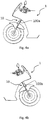
- figure 4a shows a left-side view of a motorcycle (vehicle) 1 having a front fork 10
- figure 4b shows a right-side view of the same motorcycle 1 with the front fork 10.
- the compression front fork leg 100a is visible
- the rebound front fork leg 100b is visible.
Priority Applications (6)
| Application Number | Priority Date | Filing Date | Title |
|---|---|---|---|
| EP17173880.0A EP3409972A1 (de) | 2017-06-01 | 2017-06-01 | Unter druck stehendes, teleskopisches bein einer vordergabel, vordergabel und fahrzeug |
| EP18728885.7A EP3631233A1 (de) | 2017-06-01 | 2018-06-01 | Unter druck stehendes, teleskopisches bein einer vordergabel, vordergabel und fahrzeug |
| JP2019566138A JP7171620B2 (ja) | 2017-06-01 | 2018-06-01 | 加圧される伸縮式フロントフォークレッグ、フロントフォーク、および乗物 |
| CN201880049929.XA CN110998129B (zh) | 2017-06-01 | 2018-06-01 | 加压伸缩式前叉腿、前叉和车辆 |
| PCT/EP2018/064518 WO2018220202A1 (en) | 2017-06-01 | 2018-06-01 | Pressurized telescopic front fork leg, front fork and vehicle |
| US16/696,592 US11345431B2 (en) | 2017-06-01 | 2019-11-26 | Pressurized telescopic front fork leg, front fork and vehicle |
Applications Claiming Priority (1)
| Application Number | Priority Date | Filing Date | Title |
|---|---|---|---|
| EP17173880.0A EP3409972A1 (de) | 2017-06-01 | 2017-06-01 | Unter druck stehendes, teleskopisches bein einer vordergabel, vordergabel und fahrzeug |
Publications (1)
| Publication Number | Publication Date |
|---|---|
| EP3409972A1 true EP3409972A1 (de) | 2018-12-05 |
Family
ID=59021304
Family Applications (2)
| Application Number | Title | Priority Date | Filing Date |
|---|---|---|---|
| EP17173880.0A Withdrawn EP3409972A1 (de) | 2017-06-01 | 2017-06-01 | Unter druck stehendes, teleskopisches bein einer vordergabel, vordergabel und fahrzeug |
| EP18728885.7A Pending EP3631233A1 (de) | 2017-06-01 | 2018-06-01 | Unter druck stehendes, teleskopisches bein einer vordergabel, vordergabel und fahrzeug |
Family Applications After (1)
| Application Number | Title | Priority Date | Filing Date |
|---|---|---|---|
| EP18728885.7A Pending EP3631233A1 (de) | 2017-06-01 | 2018-06-01 | Unter druck stehendes, teleskopisches bein einer vordergabel, vordergabel und fahrzeug |
Country Status (5)
| Country | Link |
|---|---|
| US (1) | US11345431B2 (de) |
| EP (2) | EP3409972A1 (de) |
| JP (1) | JP7171620B2 (de) |
| CN (1) | CN110998129B (de) |
| WO (1) | WO2018220202A1 (de) |
Families Citing this family (2)
| Publication number | Priority date | Publication date | Assignee | Title |
|---|---|---|---|---|
| JP7030081B2 (ja) * | 2019-06-27 | 2022-03-04 | 本田技研工業株式会社 | 鞍乗り型車両のフロントフォーク下部構造 |
| EP3809012A1 (de) | 2019-10-18 | 2021-04-21 | Öhlins Racing AB | Vordergabelpositionsabhängige dämpfung für fahrräder und motorräder |
Citations (5)
| Publication number | Priority date | Publication date | Assignee | Title |
|---|---|---|---|---|
| GB1499396A (en) * | 1975-04-19 | 1978-02-01 | Tokico Ltd | Shock absorber |
| DE2742700A1 (de) * | 1976-09-22 | 1978-03-30 | Kayaba Industry Co Ltd | Federbein fuer radaufhaengungen an motorraedern |
| JPS5614637A (en) * | 1979-07-17 | 1981-02-12 | Yamaha Motor Co Ltd | Gas chamber construction for shock absorber |
| DE3843615A1 (de) * | 1988-12-23 | 1990-07-05 | Bayerische Motoren Werke Ag | Aufpralldaempfer fuer kraftfahrzeuge |
| DE102011010070A1 (de) * | 2011-02-01 | 2012-08-02 | Hydac Technology Gmbh | Hydropneumatische Kolbenzylinderanordnung |
Family Cites Families (17)
| Publication number | Priority date | Publication date | Assignee | Title |
|---|---|---|---|---|
| DE2519372A1 (de) * | 1975-04-30 | 1976-11-11 | Tokico Ltd | Stossdaempfer |
| JP3381961B2 (ja) * | 1993-03-18 | 2003-03-04 | 株式会社ショーワ | 自転車用車輪懸架装置 |
| JP2005054863A (ja) * | 2003-08-01 | 2005-03-03 | Showa Corp | 油圧緩衝器 |
| JP2005220926A (ja) * | 2004-02-03 | 2005-08-18 | Kayaba Ind Co Ltd | オイルロック構造 |
| SE529042C2 (sv) * | 2004-12-06 | 2007-04-17 | Oehlins Racing Ab | Teleskopgaffelben |
| JP4704298B2 (ja) * | 2005-10-11 | 2011-06-15 | カヤバ工業株式会社 | 内外筒の連結構造 |
| US10036443B2 (en) * | 2009-03-19 | 2018-07-31 | Fox Factory, Inc. | Methods and apparatus for suspension adjustment |
| JP5240571B2 (ja) * | 2009-02-16 | 2013-07-17 | 本田技研工業株式会社 | フロントフォーク |
| US8256787B2 (en) * | 2009-10-08 | 2012-09-04 | Shimano Inc. | Adjustable bicycle suspension system |
| JP5438484B2 (ja) | 2009-12-03 | 2014-03-12 | カヤバ工業株式会社 | 油圧緩衝器 |
| DE102011000280B4 (de) * | 2011-01-21 | 2014-10-30 | Wp Performance Systems Gmbh | Teleskopfedergabelbein mit Ausgleichsvolumen für Dämpfungsfluid |
| JP5961033B2 (ja) * | 2012-04-27 | 2016-08-02 | 株式会社ショーワ | 緩衝器及び油圧緩衝器 |
| JP6114652B2 (ja) | 2013-07-16 | 2017-04-12 | Kyb株式会社 | 緩衝器 |
| KR101673700B1 (ko) | 2013-12-24 | 2016-11-07 | 가부시키가이샤 니프코 | 스프레이 노즐 |
| JP6291266B2 (ja) * | 2014-01-27 | 2018-03-14 | 株式会社ショーワ | フロントフォーク |
| EP3218250A1 (de) * | 2014-11-10 | 2017-09-20 | Öhlins Racing AB | Entfernbares einsatzsystem |
| JP6475527B2 (ja) * | 2015-03-18 | 2019-02-27 | Kybモーターサイクルサスペンション株式会社 | フロントフォーク |
-
2017
- 2017-06-01 EP EP17173880.0A patent/EP3409972A1/de not_active Withdrawn
-
2018
- 2018-06-01 WO PCT/EP2018/064518 patent/WO2018220202A1/en active Application Filing
- 2018-06-01 JP JP2019566138A patent/JP7171620B2/ja active Active
- 2018-06-01 CN CN201880049929.XA patent/CN110998129B/zh active Active
- 2018-06-01 EP EP18728885.7A patent/EP3631233A1/de active Pending
-
2019
- 2019-11-26 US US16/696,592 patent/US11345431B2/en active Active
Patent Citations (5)
| Publication number | Priority date | Publication date | Assignee | Title |
|---|---|---|---|---|
| GB1499396A (en) * | 1975-04-19 | 1978-02-01 | Tokico Ltd | Shock absorber |
| DE2742700A1 (de) * | 1976-09-22 | 1978-03-30 | Kayaba Industry Co Ltd | Federbein fuer radaufhaengungen an motorraedern |
| JPS5614637A (en) * | 1979-07-17 | 1981-02-12 | Yamaha Motor Co Ltd | Gas chamber construction for shock absorber |
| DE3843615A1 (de) * | 1988-12-23 | 1990-07-05 | Bayerische Motoren Werke Ag | Aufpralldaempfer fuer kraftfahrzeuge |
| DE102011010070A1 (de) * | 2011-02-01 | 2012-08-02 | Hydac Technology Gmbh | Hydropneumatische Kolbenzylinderanordnung |
Also Published As
| Publication number | Publication date |
|---|---|
| CN110998129A (zh) | 2020-04-10 |
| JP7171620B2 (ja) | 2022-11-15 |
| EP3631233A1 (de) | 2020-04-08 |
| US20200094913A1 (en) | 2020-03-26 |
| WO2018220202A1 (en) | 2018-12-06 |
| JP2020521923A (ja) | 2020-07-27 |
| CN110998129B (zh) | 2021-12-03 |
| US11345431B2 (en) | 2022-05-31 |
Similar Documents
| Publication | Publication Date | Title |
|---|---|---|
| US11293513B2 (en) | Method and apparatus for an adjustable damper | |
| US7513490B2 (en) | Shock absorber assembly | |
| US10370058B2 (en) | Removable insert system | |
| US11345431B2 (en) | Pressurized telescopic front fork leg, front fork and vehicle | |
| US20170356518A1 (en) | Spring unit | |
| JP6259215B2 (ja) | フロントフォーク | |
| WO2016024538A1 (ja) | フロントフォーク | |
| US11592074B2 (en) | Position-dependent shock absorber | |
| JP5202426B2 (ja) | 緩衝器 | |
| JP2008298137A (ja) | 油圧緩衝器 | |
| JP2010230068A (ja) | 油圧緩衝器 | |
| JP2011033053A (ja) | 油圧緩衝器 | |
| JP2020003025A (ja) | フロントフォーク | |
| JP2010038171A (ja) | 油圧緩衝器 | |
| JP2011047503A (ja) | 油圧緩衝器 |
Legal Events
| Date | Code | Title | Description |
|---|---|---|---|
| PUAI | Public reference made under article 153(3) epc to a published international application that has entered the european phase |
Free format text: ORIGINAL CODE: 0009012 |
|
| STAA | Information on the status of an ep patent application or granted ep patent |
Free format text: STATUS: THE APPLICATION HAS BEEN PUBLISHED |
|
| AK | Designated contracting states |
Kind code of ref document: A1 Designated state(s): AL AT BE BG CH CY CZ DE DK EE ES FI FR GB GR HR HU IE IS IT LI LT LU LV MC MK MT NL NO PL PT RO RS SE SI SK SM TR |
|
| AX | Request for extension of the european patent |
Extension state: BA ME |
|
| STAA | Information on the status of an ep patent application or granted ep patent |
Free format text: STATUS: THE APPLICATION IS DEEMED TO BE WITHDRAWN |
|
| 18D | Application deemed to be withdrawn |
Effective date: 20190606 |