EP3407145B1 - Fpga-basierter rechteckwellengenerator und verfahren zur erzeugung von rechteckwellen - Google Patents
Fpga-basierter rechteckwellengenerator und verfahren zur erzeugung von rechteckwellen Download PDFInfo
- Publication number
- EP3407145B1 EP3407145B1 EP16885492.5A EP16885492A EP3407145B1 EP 3407145 B1 EP3407145 B1 EP 3407145B1 EP 16885492 A EP16885492 A EP 16885492A EP 3407145 B1 EP3407145 B1 EP 3407145B1
- Authority
- EP
- European Patent Office
- Prior art keywords
- square wave
- delay
- wave signal
- clock
- waveform data
- Prior art date
- Legal status (The legal status is an assumption and is not a legal conclusion. Google has not performed a legal analysis and makes no representation as to the accuracy of the status listed.)
- Active
Links
Images
Classifications
-
- G—PHYSICS
- G06—COMPUTING OR CALCULATING; COUNTING
- G06F—ELECTRIC DIGITAL DATA PROCESSING
- G06F13/00—Interconnection of, or transfer of information or other signals between, memories, input/output devices or central processing units
- G06F13/38—Information transfer, e.g. on bus
- G06F13/382—Information transfer, e.g. on bus using universal interface adapter
- G06F13/387—Information transfer, e.g. on bus using universal interface adapter for adaptation of different data processing systems to different peripheral devices, e.g. protocol converters for incompatible systems, open system
-
- G—PHYSICS
- G04—HOROLOGY
- G04F—TIME-INTERVAL MEASURING
- G04F10/00—Apparatus for measuring unknown time intervals by electric means
-
- G—PHYSICS
- G06—COMPUTING OR CALCULATING; COUNTING
- G06F—ELECTRIC DIGITAL DATA PROCESSING
- G06F1/00—Details not covered by groups G06F3/00 - G06F13/00 and G06F21/00
- G06F1/04—Generating or distributing clock signals or signals derived directly therefrom
- G06F1/14—Time supervision arrangements, e.g. real time clock
-
- G—PHYSICS
- G06—COMPUTING OR CALCULATING; COUNTING
- G06F—ELECTRIC DIGITAL DATA PROCESSING
- G06F13/00—Interconnection of, or transfer of information or other signals between, memories, input/output devices or central processing units
- G06F13/38—Information transfer, e.g. on bus
Definitions
- the present disclosure relates to the technical field of square wave generation, and in particular, to a square wave generator and a method for generating a square wave based on a Field Programmable Gate Array (FPGA).
- FPGA Field Programmable Gate Array
- US 4 468 746 A discloses an apparatus for determining interval between two events.
- the interval between first and second events which may occur in a period less than a nanosecond interval, is determined with a square wave clock source started in response to the first event.
- the source derives a square wave having a first transition when started and equally spaced succeeding transitions spaced from each other by T/2, where T is the square wave period.
- a delay network having N taps is responsive to the square wave, whereby (N+1) square waves are derived.
- the taps are spaced from each other so the clock source square wave is delayed at tap k by kT/n, where n is a predetermined integer greater than 1 and k is selectively every integer from 1 to N.
- (N+1) memory elements respectively respond to the (N+1) square waves to generate a signal indicative of which half cycle of each of the (N+1) square wave is being derived when the second event occurs.
- the waveform generating device comprises a waveform generating management module based on a FPGA (Field Programmable Gate Array) and a peripheral circuit expansion module.
- the waveform generating management module comprises a core management unit, a data transmission control unit, a storage control unit, a system clock management unit and a data rate acceleration unit, wherein the data transmission control unit is connected to the core management unit; the storage control unit is connected to the core management unit; the system clock management unit is connected to the core management unit; and the data rate acceleration unit is used for outputting waveform data at an accelerated output rate.
- the peripheral circuit expansion module comprises a data transmission bus control unit, a storage unit, a digital-analog conversion unit and an output clock management unit. The invention is high in flexibility and can achieve a high-speed digital waveform generation and control function.
- CN 104 597 748 A discloses a FPGA (field programmable gate array) chip-based TDC (time-digital converter).
- the TDC comprises a pulse signal generator, a multi-tap signal delay chain, a trigger array, two parallel signal change edge search circuits, a rising edge 'one-hot' coding circuit, a falling edge 'one-hot' coding circuit, a calibration circuit and a conversion result output circuit, wherein the rising edge 'one-hot' coding circuit is parallel to the falling edge 'one-hot' coding circuit;
- the pulse signal generator is used for generating a negative pulse and feeding the negative pulse into the signal delay chain;
- the trigger array is used for latching states of all taps; after the taps are resorted, the states of the taps are transmitted to the signal change edge search circuits to search a rising edge and a falling edge of the negative pulse respectively, and corresponding 'one-hot' codes are generated.
- the TDC can remove 0 delay units on the delay chain to the maximum extent, reduce 'bubbling' phenomena in latch-state thermometer codes and enable performance indexes in three aspects of measurement precision, measurement dead time and resource occupancy to be reasonably balanced so as to realize a high-performance measurement system of the TDC.
- square wave generators have been widely applied in fields of electronic science and technology, communications, physics, chemistry, biology, and even medical science.
- Square waves with high-speed and high-precision can be applied to situations such as ultrasonic, radar, medical imaging, communications, and laser control, and to frontier scientific research fields such as electron paramagnetic resonance, nuclear magnetic resonance, and mass spectrometry.
- frontier scientific research fields such as electron paramagnetic resonance, nuclear magnetic resonance, and mass spectrometry.
- a resolution of the square wave may be controlled to be 2 ns by using a high-speed clock.
- a (Double Date Rate) DDR is adopted to store waveform data, and communication with a master computer for transmitting a waveform parameter is achieved via an Ethernet or a PCI bus.
- the digital logics of the FPGA reads the waveform parameters from the DDR, and outputs a waveform by using the high-speed serialization technology after completing the waveform analysis.
- a minimum limit of a width of the square wave is 12 ns according to a waveform data storage framework based on DDR3.
- DTC Digital to Time Convert, digital-to-time converter
- PLL Phase Locked Loop
- an issue for those skilled in the art to address is to provide a square wave generator which can continuously output the square wave with high precision, large dynamic range and low dead time and to provide a method for generating the square wave.
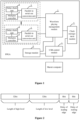
- FIG. 1 is a schematic structural diagram of a square wave generator based on an FPGA according to the present disclosure.
- the square wave generator includes a bus control module, a waveform playing management module 2, a parallel-in serial-out conversion module 3, a delay chain module 4, and a multiplex controller 5.
- the bus control module is configured to receive a playing instruction and a playing address which are sent by a master computer, and output the playing instruction and the playing address.
- the bus control module is a USB bus control module 1.
- USB bus control module 1 is arranged inside the FPGA, and the USB bus control module 1, which is based on a USB bus, is configured to establish communications between the FPGA and the master computer via the USB bus.
- the communications includes a downloading and updating of a control command and raw waveform data.
- bus control module herein may also be a bus control module of another type, which is not limited by the present disclosure.
- the waveform playing management module 2 is configured to receive the playing instruction and the playing address, read the raw waveform data from a storage module 6 according to the playing instruction and the playing address, decode the raw waveform data to obtain a waveform data, generate delay data according to the waveform data, and output the waveform data and the delay data.
- the storage module 6 is specifically configured to receive, via the bus control module, a storage command, a storage address, and the raw waveform data which are sent by the master computer, decode the storage address according to the storage command, and store the raw waveform data according to a decoded storage address.
- the master computer is configured to send the storage command, the storage address, and the raw waveform data to the USB bus control module 1 via the USB bus at first, and then the USB bus control module 1 sends the storage command, the storage address, and the raw waveform data to the storage module 6.
- the storage module 6 decodes the storage address, and then stores the raw waveform data into the storage module 6 according to the decoded storage address.
- each square wave signal in the raw waveform data occupies 80 bits in the storage module 6, where a first group of 32 bits in the 80 bits contains information of holding a high level in the each square wave signal, a second group of 32 bits in the 80 bits contains information of holding a low level in the each square wave signal, a third group of 8 bits in the 80 bits contains information of a delay time between a rising edge of the each square wave signal and a clock edge of the high-speed clock, and a fourth group of 8 bits in the 80 bits contains information of a delay time between a falling edge of the each square wave signal and another clock edge of the high-speed clock.
- Figure 2 is a schematic diagram of a storage structure of a square wave signal according to the present disclosure.
- the raw waveform data of the square wave with high precision is stored in the storage module 6 inside the FPGA.
- Data of each square wave signal in the raw waveform data is stored in the storage module 6 based on the structure shown in Figure 2 .
- the effective information is: a time duration for holding the high level (a logic "1"), a time duration for holding the low level (a logic "0"), and delay times for the rising edge and the falling edge of the square wave in relative to the clock edge of the high-speed clock.
- the each square wave signal occupies a total of 80 bits of data. In the 80 bits, a first group of 32 bits contains information on holding the high level (i.e.
- a second group of 32 bits contains information on holding the low level (i.e. the logic "0") in the each square wave signal, and a period T of the high-speed clock is represented by a lowest bit of these two groups of 32 bits.
- the information on the delay time between the rising edge of the each square wave signal and the clock edge of the high-speed clock i.e., a delay of a leading edge as shown in Figure 2 occupies the third group of 8 bits
- the information on the delay time between the falling edge of the each square wave signal and another clock edge of the high-speed clock i.e., a delay of a trailing edge as shown in Figure 2 occupies the fourth group of 8 bits
- a delay time of a single delay unit in the delay chain unit 4 is represented by a lowest bit of these two groups of 8 bits.
- a total delay time of the delay chain unit 4 is not shorter than the period of the high-speed clock.
- t indicating an arrival time of signal edge of the square wave signal is determined by two factors.
- One factor is time data of parallel input with relatively low precision, which is set as n 1 * T 2 , where n 1 represents total time duration of square wave signals before the current square wave signal arrives, and is determined by the sum of a high-level time and a low-level time.
- a relative delay and a pulse width of the square wave can be precisely adjusted.
- a minimum adjustable precision of the square wave is t 0 , in a case that t 0 is much shorter than T .
- the total time duration of the delay chain should cover at least the period T of the high-speed clock.
- a time interpolation for the high-speed clock is realized by using the parallel-in serial-out conversion unit 3 in the FPGA in conjunction with the delay chain unit 4, so that a time resolution that is equal to the delay time of the single delay unit in the delay chain unit 4 is obtained.
- T 2 n + 1 2 * t 0 , where n represents a positive integer.
- the two value are further analyzed and processed in the FPGA in real time, and then sent to a square wave outputting module (including the parallel-in serial-out conversion unit 3, the delay chain unit 4, and the multiplex controlling unit 5) for output.
- a square wave outputting module including the parallel-in serial-out conversion unit 3, the delay chain unit 4, and the multiplex controlling unit 5 for output.
- a precision 1/2* t 0 for adjusting the signal edge of the square wave signal is realized.
- the time precision of the square wave signal can be doubled by using time interpolation alternately. Meanwhile, a characteristic of an outputting square wave at a high speed is also ensured, without influencing other basic parameters of the square wave generator such as a dead time and a dynamic range.
- n is 12 and t 0 is 50 ps.
- T is 1.25 ns and the time resolution is t 0 2 , i.e. 25 ps. Hence, the precision is high.
- n and t 0 are determined according to a practical implementation, and different values may be set for different square wave generators.
- the parallel-in serial-out conversion unit 3 is configured to receive the waveform data inputted in parallel, and output the waveform data in serial to obtain a square wave signal.
- the parallel-in serial-out conversion unit 3 is configured to receive, according to a system clock, the waveform data inputted in parallel, and output, according to the high-speed clock, the square wave signal in serial in a DDR manner, where a frequency of the high-speed clock is 4 times as large as a frequency of the system clock.
- the delay chain unit 4 is configured to delay the square wave signal
- the delay chain unit 4 is capable to achieve high-precision delay on the square wave signal and obtain an output of the square wave signal with high time resolution.
- the multiplex controller 5 is configured to receive the delay data, determine an output node of the square wave signal on the delay chain unit 4 according to the delay data, obtain from the output node a delayed square wave signal corresponding to the output node, and output the delayed square wave signal.
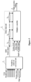
- Figure 3 is a schematic structural diagram of a square wave outputting module according to the present disclosure.
- the square wave outputting module herein includes the parallel-in serial-out conversion unit 3, the delay chain unit 4, and the multiplex controller 5. Moreover, multiple square wave outputting modules may be included in the square wave generator. A specific quantity of the multiple square wave outputting modules is not limited herein according to the present disclosure.
- the square wave outputting module is an important part of the present disclosure.
- the square wave outputting module is configured to perform time interpolation on the high-speed clock to output the square wave signal having higher time resolution and no dead time.
- a diagram of an internal structural diagram of the square wave outputting module is shown in Figure 3 .
- An operating clock of the parallel-in serial-out conversion unit 3 and the multiplex controller 5 is a system clock.
- the high-speed clock is an output reference clock for the high-speed square wave, and the frequency of the high-speed clock is 4 times as large as the frequency of the system clock.
- the parallel-in serial-out conversion unit 3 outputs the square wave signal at both the rising edge and the falling edge of the high-speed clock, namely, outputs at a double-rate output (Double Data Rate, DDR).
- DDR Double Data Rate
- 8-bit parallel waveform data is inputted into the parallel-in serial-out conversion unit 3 according to the system clock.
- the parallel-in serial-out conversion unit 3 outputs, according to the high-speed clock a square wave signal with 8 bits per period of the system clock in the DDR manner.
- the square wave signal outputted in serial by the parallel conversion unit 3 is sent to the delay chain unit 4.
- the multiplex controller 5 determines, according to the inputted delay data in real time, a sequence number of the output node of the delay chain unit 4, obtains a delayed square wave signal corresponding to the output node from the output node, and outputs the delayed square wave signal. Different output nodes in the delay chain correspond to different delays.
- the time precision of the square wave is equal to the time delay t 0 of the single delay unit in the delay chain unit 4.
- a square wave with high precision can be generated. Meanwhile, the capability to output a sequence of square wave at a high speed is ensured, where the square wave has no dead time and a dynamic range from nanoseconds to seconds.
- the square wave generator further comprises a clock management module 7.
- the clock management module 7 is configured to receive a reference clock inputted externally, and generate, according to the reference clock, an operating clock for the bus control module, the waveform playing management module 2, the parallel-in serial-out conversion unit 3, and the multiplex controller 5, where the operating clock is the system clock.
- the clock management module 7 is further configured to generate, according to the reference clock, the high-speed clock for the parallel-in serial-out conversion unit 3.
- the square wave generator provided by the present disclosure is based on the FPGA.
- the FPGA selected in the present disclosure is a Virtex-7 FPGA of an SRAM type.
- the Virtex-7 FPGA is based on a look-up table having six inputs. A 28 nm CMOS process is applied in this FPGA so that more than 10 million gate circuits and thousands of customizable I/O can be integrated into a single chip.
- the Virtex-7 FPGA has a highest integration and a good performance.
- the storage module 6, which is generated by calling internal resources of the FPGA, is configured to store the waveform data for the square wave generator having a high-speed and high-precision based on the FPGA.
- the USB bus control module 1 is arranged inside the FPGA so as to establish communications between the FPGA and the master computer via the USB bus, where the communications includes a downloading and updating of a control command and waveform data.
- Data decoding, control and state management is performed in a playing process of the square wave waveform by the waveform playing management module 2 using logic resources of the FPGA.
- a function to output the high-precision square wave is further realized in conjunction with the high-speed parallel-in serial-out conversion unit 3 and the delay chain unit 4 in the FPGA.
- the clock management module 7 is designed by using clock management resources inside the FPGA.
- the operating clock for the USB bus control module 1, the memory module 6, the waveform playing management module 2, and the high-speed square wave outputting module (including the parallel-in serial-out conversion unit 3, the delay chain unit 4, and the multiplex controller 5) is generated based on the reference clock which is externally inputted.
- the square wave generator based on the Virtex-7 FPGA is of low cost.
- a multi-channel superposed waveform generator is achieved by using the Virtex-7 FPGA as a key processing chip.
- a cost of a single FPGA chip is about 20,000-30,000 Chinese yuan, and a total cost of a single device is about 40,000 Chinese yuan, where this price is equal to the price of a Pulseblaster with a time resolution of mere 1-2 ns.
- modifications may only be made to logic configurations inside the FPGA, rather than hardware configurations, which can greatly reduce a cost of secondary development.
- a square wave generating function having 10 channels with high-speed and high-resolution is achieved in a Virtex-7 FPGA XC7V485T-2 of a SRAM type.
- the time resolution of the square wave obtained by the time interpolation based on the delay chain can be approximate 50 ps, with no dead time in outputting the square wave and with a dynamic range from 5 ns to seconds. Time precision can be improved to 25 ps by using the time interpolation alternately further.
- the square wave generator based on the Virtex-7 FPGA is of high performance and high level of integration.
- the Virtex-7 FPGA with characteristics of high performance and a high speed are used as a basis of the design.
- a generating and outputting structure of a digital signal are optimized.
- Limitations of the conventional technology are broken, and a performance comparable to a customized ASIC can be obtained.
- Multiple square wave generating channels can be integrated into a single FPGA, which greatly improves an integration level of a system.
- a square wave generator with high speed, high precision, low cost, strong design flexibility and high integration level is realized based on the Virtex-7 FPGA, which can be applied to many implementations.
- the Virtex-7 FPGA By using the high performance and re-programmability of the Virtex-7 FPGA, various functions in various implementations can be realized according to this disclosure.
- the function to generate a high-performance square wave is improved while ensuring flexibility thereof.
- the square wave generator based on the FPGA has high precision and no dead time.
- the time interpolation is performed on the high-speed clock by using the delay chain method, which improves the time resolution of the square wave signal while retaining characteristics of continuously outputting the high-precision square wave with a high speed and without the dead time.
- Using the time interpolation alternately can double the precision of the square wave generator without influencing performance indexes.
- the square wave generator based on the FPGA has a large dynamic range.
- the level holding time of the outputted square wave signal has a very large dynamic range, so that the square wave generator can be applied to various application scenes.
- the square wave generator based on the FPGA is of flexibility in implementation. Flexibility is a biggest advantage for a superposed waveform generator based on the FPGA with a high speed and a high resolution. A similar high-performance waveform generator based on a customized ASIC chip generally has limited functions due to a fixed function of the ASIC. It is difficult to adapt to an application scene which requires high flexibility.
- the square wave generator based on the FPGA greatly utilizes a reprogrammable characteristic of the FPGA. Different requirements can be met by a few modifications to an FPGA code, which does not require any modification on hardware. Development based on the FPGA also simplifies a developing process and difficulties thereof. In addition, the present disclosure is applicable to most application scenes which require the square wave signal due to the characteristics of high precision, no dead time and large dynamic range, and thereby having a good flexibility in application.
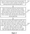
- FIG. 4 is a flowchart of a method for generating a square wave based on an FPGA according to the present disclosure. The method includes steps S101 to S103.
- step S101 a playing instruction and a playing address which are sent by a master computer are received, and the playing instruction and the playing address are outputted.
- step S102 the playing instruction and the playing address are received, raw waveform data is read from an storage module according to the playing instruction and the playing address, the raw waveform data is decoded to obtain waveform data, delay data is generated according to the waveform data, and the waveform data and the delay data are outputted.
- step S103 the waveform data inputted in parallel is received, the waveform data is outputted in serial to obtain a square wave signal, the square wave signal is delayed, the delay data is received, an output node of the square wave signal on a delay chain unit is determined according to the delay data, a delayed square wave signal corresponding to the output node is obtained from the output node, and the delayed square wave signal is outputted.
- a detailed description of the method for generating the square wave based on the FPGA may be referred to the description of the square wave generator, and is not further described herein.
- the method for generating the square wave based on the FPGA includes receiving the delay data, determining, according to the delay data, the output node of the square wave signal on the delay chain unit, obtaining the delayed square wave signal corresponding to the output node from the output node, and outputting the delayed square wave signal. Therefore, the precision of the square wave finally outputted by the square wave generator is a delay time of one single delay unit in the delay chain unit.
- the delay time of the single delay unit in the delay chain unit is as short as picoseconds, so that the square wave signal can be continuously outputted with high precision and no dead time.
- a process, a method, an article or a device including a combination of elements include the disclosed combination of elements, and may further include other elements that are not enumerated, or further include inherent elements of the process, the method, the article or the device. Unless specifically limited, the statement “including/comprising" does not exclude a case that other similar elements may exist in the process, the method, the article or the device other than the combination of elements.
Landscapes
- Engineering & Computer Science (AREA)
- Theoretical Computer Science (AREA)
- Physics & Mathematics (AREA)
- General Physics & Mathematics (AREA)
- General Engineering & Computer Science (AREA)
- Pulse Circuits (AREA)
Claims (10)
- Rechteckwellengenerator auf Basis eines Field Programmable Gate Array (FPGA), umfassend:ein Bussteuermodul (1) zum Empfangen eines Abspielbefehls und einer Abspieladresse, die von einem Master-Computer sendbar sind, und zum Ausgeben des Abspielbefehls und der Abspieladresse,ein Wellenformabspielverwaltungsmodul (2) zum Empfangen des Abspielbefehls und der Abspieladresse, Auslesen von Wellenformrohdaten aus einem Speichermodul (6) gemäß dem Abspielbefehl und der Abspieladresse, Decodieren der Wellenformrohdaten zum Erhalten von Wellenformdaten, Erzeugen von Verzögerungsdaten gemäß den Wellenformdaten und Ausgeben der Wellenformdaten und der Verzögerungsdaten; undein Rechteckwellenausgabemodul zum Durchführen einer Zeitinterpolation an einem Hochgeschwindigkeitstakt nach einem Verzögerungszeitkettenverfahren, wobei das Rechteckwellenausgabemodul eine Paralleleingangs-/Reihenausgangswandlereinheit (3), eine Verzögerungsketteneinheit (4) und einen Multiplex-Regler (5) umfasst, wobeidie Paralleleingangs-/Reihenausgangswandlereinheit (3) dazu ausgebildet ist, die parallel eingegebenen Wellenformdaten zu empfangen, sowohl an einer steigenden Flanke als auch an einer fallenden Flanke des Hochgeschwindigkeitstakts ein Rechtecksignal in Reihe auszugeben und das Rechtecksignal an die Verzögerungsketteneinheit (4) zu senden;die Verzögerungsketteneinheit (4) dazu ausgebildet ist, das Rechtecksignal zu verzögern; undder Multiplex-Regler (5) dazu ausgebildet ist, die Verzögerungsdaten zu empfangen, anhand der eingegebenen Verzögerungsdaten in Echtzeit eine Sequenznummer eines Ausgangsknotens der Verzögerungsketteneinheit (4) zu bestimmen, ein dem Ausgangsknoten entsprechendes verzögertes Rechtecksignal von dem Ausgangsknoten zu erhalten und das verzögerte Rechtecksignal auszugeben,wobei unterschiedliche Ausgangsknoten in einer Verzögerungskette unterschiedlichen Verzögerungen entsprechen und eine Zeitgenauigkeit des verzögerten Rechtecksignals einer Zeitverzögerung einer einzelnen Verzögerungseinheit in der Verzögerungsketteneinheit (4) entspricht.
- Rechteckwellengenerator auf FPGA-Basis nach Anspruch 1, wobei die Paralleleingangs-/Reihenausgangswandlereinheit (3) dazu ausgebildet ist, die parallel eingegebenen Wellenformdaten gemäß einem Systemtakt zu empfangen und das Rechtecksignal nach einem Double Date Rate (DDR)-Verfahren gemäß dem Hochgeschwindigkeitstakt in Reihe auszugeben; wobei eine Frequenz des Hochgeschwindigkeitstakts das Vierfache einer Frequenz des Systemtakts beträgt.
- Rechteckwellengenerator auf FPGA-Basis nach Anspruch 2, wobei die Verzögerungsdaten ein Verhältnis t umfassen, das eine Ankunftszeit einer Signalflanke des Rechtecksignals angibt, wobei
 n 1 für eine Gesamtdauer von Rechtecksignalen vor der Ankunft eines aktuellen Rechtecksignal steht;T für eine Periode des Hochgeschwindigkeitstakts steht;n 2 für eine Sequenznummer des Ausgangsknotens zur Ausgabe eines Signals in der Verzögerungsketteneinheit steht;t 0 für eine Verzögerungszeit der einzelnen Verzögerungseinheit in der Verzögerungsketteneinheit steht; undwobei eine Gesamtverzögerungszeit der Verzögerungsketteneinheit nicht kürzer als die Periode des Hochgeschwindigkeitstakts ist.
 - Rechteckwellengenerator auf FPGA-Basis nach Anspruch 3, wobei

- Rechteckwellengenerator auf FPGA-Basis nach Anspruch 4, wobei n 12 beträgt und t 0 50 ps beträgt.
- Rechteckwellengenerator auf FPGA-Basis nach Anspruch 1, wobei das Speichermodul (6) dazu ausgebildet ist, über das Bussteuermodul (1) einen Speicherbefehl, eine Speicheradresse und die Wellenformrohdaten zu empfangen, die durch den Master-Computer sendbar sind, die Speicheradresse auf Basis des Speicherbefehls zu decodieren und die Wellenformrohdaten gemäß einer decodierten Speicheradresse zu speichern.
- Rechteckwellengenerator auf FPGA-Basis nach Anspruch 7, wobei die Rechtecksignale der Wellenformrohdaten jeweils 80 Bits in dem Speichermodul (6) belegen, wobei eine erste Gruppe von 32 Bits in den 80 Bits Informationen bezüglich eines Haltens eines hohen Pegels in dem betreffenden Rechtecksignal enthält, eine zweite Gruppe von 32 Bits in den 80 Bits Informationen bezüglich eines Haltens eines niedrigen Pegels in dem betreffenden Rechtecksignal enthält, eine dritte Gruppe von 8 Bits in den 80 Bits Informationen bezüglich einer Verzögerungszeit zwischen einer steigenden Flanke des betreffenden Rechtecksignals und einer Taktflanke des Hochgeschwindigkeitstakts enthält und eine vierte Gruppe von 8 Bits in den 80 Bits Informationen bezüglich einer Verzögerungszeit zwischen einer fallenden Flanke des betreffenden Rechtecksignals und einer weiteren Taktflanke des Hochgeschwindigkeitstakts enthält.
- Rechteckwellengenerator auf FPGA-Basis nach Anspruch 1, des Weiteren umfassend:
ein Taktverwaltungsmodul (7), das dazu ausgebildet ist:einen extern eingegebenen Referenztakt zu empfangen;gemäß dem Referenztakt einen Betriebstakt für das Bussteuermodul (1), das Wellenformabspielverwaltungsmodul (2), die Paralleleingangs-/Reihenausgangswandlereinheit (3) und den Multiplex-Regler (5) zu erzeugen; wobei der Betriebstakt der Systemtakt ist; undgemäß dem Referenztakt den Hochgeschwindigkeitstakt für die Paralleleingangs-/Reihenausgangswandlereinheit zu erzeugen. - Rechteckwellengenerator auf FPGA-Basis nach Anspruch 1, wobei das Bussteuermodul (1) ein Universal Serial Bus(USB)-Bussteuermodul ist.
- Verfahren zur Erzeugung einer Rechteckwelle auf Basis eines FPGA nach einem der Ansprüche 1 bis 9, wobei das Verfahren folgende Schritte umfasst:Empfangen eines Abspielbefehls und einer Abspieladresse, die von einem Master-Computer gesendet werden, und Ausgeben des Abspielbefehls und der Abspieladresse (101);Empfangen des Abspielbefehls und der Abspieladresse, Auslesen von Wellenformrohdaten aus einem Speichermodul gemäß dem Abspielbefehl und der Abspieladresse; Decodieren der Wellenformrohdaten, um Wellenformdaten zu erhalten; Erzeugen von Verzögerungsdaten gemäß den Wellenformdaten und Ausgeben der Wellenformdaten und der Verzögerungsdaten (102); undDurchführen einer Zeitinterpolation an einem Hochgeschwindigkeitstakt nach einem Verzögerungszeitkettenverfahren,wobei der Schritt des Durchführens einer Zeitinterpolation an einem Hochgeschwindigkeitstakt nach einem Verzögerungszeitkettenverfahren Folgendes umfasst:Empfangen der parallel eingegebenen Wellenformdaten und Ausgeben eines Rechtecksignals in Reihe sowohl an einer steigenden Flanke als auch an einer fallenden Flanke des Hochgeschwindigkeitstakts;Verzögern des Rechtecksignals; undEmpfangen der Verzögerungsdaten; Bestimmen eine Sequenznummer eines Ausgangsknotens der Verzögerungsketteneinheit in Echtzeit anhand der eingegebenen Verzögerungsdaten, Erhalten eines dem Ausgangsknoten entsprechenden verzögerten Rechtecksignals von dem Ausgangsknoten und Ausgeben des verzögerten Rechtecksignals (103),wobei unterschiedliche Ausgangsknoten in einer Verzögerungskette unterschiedlichen Verzögerungen entsprechen und eine Zeitgenauigkeit des verzögerten Rechtecksignals einer Zeitverzögerung einer einzelnen Verzögerungseinheit in der Verzögerungsketteneinheit entspricht.
Applications Claiming Priority (1)
| Application Number | Priority Date | Filing Date | Title |
|---|---|---|---|
| PCT/CN2016/071182 WO2017124219A1 (zh) | 2016-01-18 | 2016-01-18 | 一种基于fpga的方波发生器及方法 |
Publications (3)
| Publication Number | Publication Date |
|---|---|
| EP3407145A1 EP3407145A1 (de) | 2018-11-28 |
| EP3407145A4 EP3407145A4 (de) | 2019-09-11 |
| EP3407145B1 true EP3407145B1 (de) | 2024-05-01 |
Family
ID=59361102
Family Applications (1)
| Application Number | Title | Priority Date | Filing Date |
|---|---|---|---|
| EP16885492.5A Active EP3407145B1 (de) | 2016-01-18 | 2016-01-18 | Fpga-basierter rechteckwellengenerator und verfahren zur erzeugung von rechteckwellen |
Country Status (3)
| Country | Link |
|---|---|
| US (1) | US10733126B2 (de) |
| EP (1) | EP3407145B1 (de) |
| WO (1) | WO2017124219A1 (de) |
Families Citing this family (10)
| Publication number | Priority date | Publication date | Assignee | Title |
|---|---|---|---|---|
| WO2019153288A1 (zh) | 2018-02-11 | 2019-08-15 | 中国科学技术大学 | 一种序列信号发生器及序列信号产生方法 |
| CN109471354B (zh) * | 2018-12-13 | 2020-09-08 | 中国科学院国家授时中心 | 一种用于精密时间间隔测量的死区补偿装置及方法 |
| CN111653302A (zh) * | 2020-06-15 | 2020-09-11 | 浪潮集团有限公司 | 一种高性能ddr读数据控制电路 |
| CN112565778B (zh) * | 2020-12-28 | 2022-04-26 | 山东神戎电子股份有限公司 | 一种基于时间片管理的数据存取方法 |
| CN114968123B (zh) * | 2022-06-17 | 2025-10-28 | 西安芯海微电子科技有限公司 | 波形读取方法、波形存储方法、装置、电子设备 |
| CN115150004B (zh) * | 2022-07-01 | 2024-02-13 | 国仪量子技术(合肥)股份有限公司 | 一种窄脉冲发生器 |
| CN115809410A (zh) * | 2022-12-05 | 2023-03-17 | 成都玖锦科技有限公司 | 一种支持多目标信号播放的方法 |
| CN115580275B (zh) * | 2022-12-08 | 2023-08-01 | 国仪量子(合肥)技术有限公司 | 高精度脉冲信号产生装置、fpga芯片和信号处理设备 |
| CN116684722B (zh) * | 2023-07-27 | 2023-10-20 | 武汉精立电子技术有限公司 | Mipi c-phy信号接收装置、方法及摄像头模组测试系统 |
| CN119922053A (zh) * | 2025-04-07 | 2025-05-02 | 北京坤驰科技有限公司 | 一种基于fpga的信号波形数据动态切换方法及装置 |
Family Cites Families (8)
| Publication number | Priority date | Publication date | Assignee | Title |
|---|---|---|---|---|
| US4468746A (en) * | 1981-12-01 | 1984-08-28 | Cincinnati Electronics Corporation | Apparatus for determining interval between two events |
| US5252867A (en) * | 1992-02-14 | 1993-10-12 | Vlsi Technology, Inc. | Self-compensating digital delay semiconductor device with selectable output delays and method therefor |
| CN101478308B (zh) * | 2009-01-13 | 2011-03-30 | 北京时代民芯科技有限公司 | 基于延时锁定环的可配置频率合成电路 |
| CN201409126Y (zh) * | 2009-04-17 | 2010-02-17 | 苏州亮智科技有限公司 | 高速并行数据串行化中的时钟同步电路 |
| CN102447477B (zh) * | 2010-10-15 | 2014-05-07 | 珠海全志科技股份有限公司 | 跨异步时钟域的并串数据流实时转换传输方法和装置 |
| CN104597748B (zh) * | 2015-02-12 | 2017-05-03 | 中国科学技术大学 | 一种基于fpga的时间数字变换器 |
| CN105162437B (zh) * | 2015-08-11 | 2018-01-30 | 中国科学技术大学 | 一种波形发生装置及方法 |
| CN105718404B (zh) * | 2016-01-18 | 2018-12-14 | 中国科学技术大学 | 一种基于fpga的方波发生器及方法 |
-
2016
- 2016-01-18 EP EP16885492.5A patent/EP3407145B1/de active Active
- 2016-01-18 WO PCT/CN2016/071182 patent/WO2017124219A1/zh not_active Ceased
- 2016-01-18 US US16/070,774 patent/US10733126B2/en active Active
Also Published As
| Publication number | Publication date |
|---|---|
| EP3407145A4 (de) | 2019-09-11 |
| US20190196999A1 (en) | 2019-06-27 |
| EP3407145A1 (de) | 2018-11-28 |
| WO2017124219A1 (zh) | 2017-07-27 |
| US10733126B2 (en) | 2020-08-04 |
Similar Documents
| Publication | Publication Date | Title |
|---|---|---|
| EP3407145B1 (de) | Fpga-basierter rechteckwellengenerator und verfahren zur erzeugung von rechteckwellen | |
| CN105718404B (zh) | 一种基于fpga的方波发生器及方法 | |
| US5247656A (en) | Method and apparatus for controlling a clock signal | |
| CN107402597B (zh) | 一种数据与时钟对齐的方法、装置、介质及磁共振设备 | |
| CA2874459C (en) | Differential clock signal generator | |
| CN111399588B (zh) | 时钟信号产生电路、驱动方法及电子设备 | |
| CN109032498B (zh) | 一种多fpga的多通道采集系统的波形量化同步方法 | |
| US20130257499A1 (en) | High speed duty cycle correction and double to single ended conversion circuit for pll | |
| EP3751382B1 (de) | Sequenzsignalgenerator und sequenzsignalerzeugungsverfahren | |
| JP2009246482A (ja) | プライオリティエンコーダならびにそれを利用した時間デジタル変換器、試験装置 | |
| EP0924859A1 (de) | Logische Schaltung mit eigener Takterzeugung und zugehöriges Verfahren | |
| CN108919707B (zh) | 一种64通道高精度数据采集系统 | |
| CN108227828A (zh) | 一种序列信号发生器及序列信号产生方法 | |
| KR100270350B1 (ko) | 지연 회로 | |
| CN103338037B (zh) | 一种锁相环中时钟信号转数字信号的方法和装置 | |
| CN108333910B (zh) | 一种新型的时间数字转化器 | |
| US9362899B2 (en) | Clock regenerator | |
| US7042267B1 (en) | Gated clock circuit with a substantially increased control signal delay | |
| US7436725B2 (en) | Data generator having stable duration from trigger arrival to data output start | |
| KR101052699B1 (ko) | 이벤트 시간 측정 방법 및 회로 | |
| JP3622310B2 (ja) | 遅延回路及び信号処理装置 | |
| JP2006525750A (ja) | 波形グリッチ防止方法 | |
| CN111382093A (zh) | 数据传输接口的源同步电路 | |
| CN112711295B (zh) | 时序产生器、时序产生方法以及控制芯片 | |
| RU2262191C1 (ru) | Преобразователь кода |
Legal Events
| Date | Code | Title | Description |
|---|---|---|---|
| STAA | Information on the status of an ep patent application or granted ep patent |
Free format text: STATUS: THE INTERNATIONAL PUBLICATION HAS BEEN MADE |
|
| PUAI | Public reference made under article 153(3) epc to a published international application that has entered the european phase |
Free format text: ORIGINAL CODE: 0009012 |
|
| STAA | Information on the status of an ep patent application or granted ep patent |
Free format text: STATUS: REQUEST FOR EXAMINATION WAS MADE |
|
| 17P | Request for examination filed |
Effective date: 20180816 |
|
| AK | Designated contracting states |
Kind code of ref document: A1 Designated state(s): AL AT BE BG CH CY CZ DE DK EE ES FI FR GB GR HR HU IE IS IT LI LT LU LV MC MK MT NL NO PL PT RO RS SE SI SK SM TR |
|
| AX | Request for extension of the european patent |
Extension state: BA ME |
|
| DAV | Request for validation of the european patent (deleted) | ||
| DAX | Request for extension of the european patent (deleted) | ||
| A4 | Supplementary search report drawn up and despatched |
Effective date: 20190813 |
|
| RIC1 | Information provided on ipc code assigned before grant |
Ipc: G04F 10/00 20060101AFI20190807BHEP Ipc: G06F 13/38 20060101ALI20190807BHEP |
|
| STAA | Information on the status of an ep patent application or granted ep patent |
Free format text: STATUS: EXAMINATION IS IN PROGRESS |
|
| 17Q | First examination report despatched |
Effective date: 20211118 |
|
| GRAP | Despatch of communication of intention to grant a patent |
Free format text: ORIGINAL CODE: EPIDOSNIGR1 |
|
| STAA | Information on the status of an ep patent application or granted ep patent |
Free format text: STATUS: GRANT OF PATENT IS INTENDED |
|
| INTG | Intention to grant announced |
Effective date: 20231214 |
|
| GRAS | Grant fee paid |
Free format text: ORIGINAL CODE: EPIDOSNIGR3 |
|
| GRAA | (expected) grant |
Free format text: ORIGINAL CODE: 0009210 |
|
| STAA | Information on the status of an ep patent application or granted ep patent |
Free format text: STATUS: THE PATENT HAS BEEN GRANTED |
|
| AK | Designated contracting states |
Kind code of ref document: B1 Designated state(s): AL AT BE BG CH CY CZ DE DK EE ES FI FR GB GR HR HU IE IS IT LI LT LU LV MC MK MT NL NO PL PT RO RS SE SI SK SM TR |
|
| REG | Reference to a national code |
Ref country code: GB Ref legal event code: FG4D |
|
| REG | Reference to a national code |
Ref country code: CH Ref legal event code: EP |
|
| REG | Reference to a national code |
Ref country code: DE Ref legal event code: R096 Ref document number: 602016087345 Country of ref document: DE |
|
| REG | Reference to a national code |
Ref country code: IE Ref legal event code: FG4D |
|
| REG | Reference to a national code |
Ref country code: NL Ref legal event code: FP |
|
| P01 | Opt-out of the competence of the unified patent court (upc) registered |
Free format text: CASE NUMBER: APP_35990/2024 Effective date: 20240617 |
|
| REG | Reference to a national code |
Ref country code: LT Ref legal event code: MG9D |
|
| PG25 | Lapsed in a contracting state [announced via postgrant information from national office to epo] |
Ref country code: IS Free format text: LAPSE BECAUSE OF FAILURE TO SUBMIT A TRANSLATION OF THE DESCRIPTION OR TO PAY THE FEE WITHIN THE PRESCRIBED TIME-LIMIT Effective date: 20240901 |
|
| PG25 | Lapsed in a contracting state [announced via postgrant information from national office to epo] |
Ref country code: BG Free format text: LAPSE BECAUSE OF FAILURE TO SUBMIT A TRANSLATION OF THE DESCRIPTION OR TO PAY THE FEE WITHIN THE PRESCRIBED TIME-LIMIT Effective date: 20240501 |
|
| PG25 | Lapsed in a contracting state [announced via postgrant information from national office to epo] |
Ref country code: FI Free format text: LAPSE BECAUSE OF FAILURE TO SUBMIT A TRANSLATION OF THE DESCRIPTION OR TO PAY THE FEE WITHIN THE PRESCRIBED TIME-LIMIT Effective date: 20240501 Ref country code: HR Free format text: LAPSE BECAUSE OF FAILURE TO SUBMIT A TRANSLATION OF THE DESCRIPTION OR TO PAY THE FEE WITHIN THE PRESCRIBED TIME-LIMIT Effective date: 20240501 |
|
| PG25 | Lapsed in a contracting state [announced via postgrant information from national office to epo] |
Ref country code: GR Free format text: LAPSE BECAUSE OF FAILURE TO SUBMIT A TRANSLATION OF THE DESCRIPTION OR TO PAY THE FEE WITHIN THE PRESCRIBED TIME-LIMIT Effective date: 20240802 |
|
| PG25 | Lapsed in a contracting state [announced via postgrant information from national office to epo] |
Ref country code: PT Free format text: LAPSE BECAUSE OF FAILURE TO SUBMIT A TRANSLATION OF THE DESCRIPTION OR TO PAY THE FEE WITHIN THE PRESCRIBED TIME-LIMIT Effective date: 20240902 |
|
| REG | Reference to a national code |
Ref country code: AT Ref legal event code: MK05 Ref document number: 1683202 Country of ref document: AT Kind code of ref document: T Effective date: 20240501 |
|
| PG25 | Lapsed in a contracting state [announced via postgrant information from national office to epo] |
Ref country code: ES Free format text: LAPSE BECAUSE OF FAILURE TO SUBMIT A TRANSLATION OF THE DESCRIPTION OR TO PAY THE FEE WITHIN THE PRESCRIBED TIME-LIMIT Effective date: 20240501 |
|
| PG25 | Lapsed in a contracting state [announced via postgrant information from national office to epo] |
Ref country code: AT Free format text: LAPSE BECAUSE OF FAILURE TO SUBMIT A TRANSLATION OF THE DESCRIPTION OR TO PAY THE FEE WITHIN THE PRESCRIBED TIME-LIMIT Effective date: 20240501 |
|
| PG25 | Lapsed in a contracting state [announced via postgrant information from national office to epo] |
Ref country code: PL Free format text: LAPSE BECAUSE OF FAILURE TO SUBMIT A TRANSLATION OF THE DESCRIPTION OR TO PAY THE FEE WITHIN THE PRESCRIBED TIME-LIMIT Effective date: 20240501 |
|
| PG25 | Lapsed in a contracting state [announced via postgrant information from national office to epo] |
Ref country code: LV Free format text: LAPSE BECAUSE OF FAILURE TO SUBMIT A TRANSLATION OF THE DESCRIPTION OR TO PAY THE FEE WITHIN THE PRESCRIBED TIME-LIMIT Effective date: 20240501 |
|
| PG25 | Lapsed in a contracting state [announced via postgrant information from national office to epo] |
Ref country code: PT Free format text: LAPSE BECAUSE OF FAILURE TO SUBMIT A TRANSLATION OF THE DESCRIPTION OR TO PAY THE FEE WITHIN THE PRESCRIBED TIME-LIMIT Effective date: 20240902 Ref country code: PL Free format text: LAPSE BECAUSE OF FAILURE TO SUBMIT A TRANSLATION OF THE DESCRIPTION OR TO PAY THE FEE WITHIN THE PRESCRIBED TIME-LIMIT Effective date: 20240501 Ref country code: NO Free format text: LAPSE BECAUSE OF FAILURE TO SUBMIT A TRANSLATION OF THE DESCRIPTION OR TO PAY THE FEE WITHIN THE PRESCRIBED TIME-LIMIT Effective date: 20240801 Ref country code: LV Free format text: LAPSE BECAUSE OF FAILURE TO SUBMIT A TRANSLATION OF THE DESCRIPTION OR TO PAY THE FEE WITHIN THE PRESCRIBED TIME-LIMIT Effective date: 20240501 Ref country code: IS Free format text: LAPSE BECAUSE OF FAILURE TO SUBMIT A TRANSLATION OF THE DESCRIPTION OR TO PAY THE FEE WITHIN THE PRESCRIBED TIME-LIMIT Effective date: 20240901 Ref country code: HR Free format text: LAPSE BECAUSE OF FAILURE TO SUBMIT A TRANSLATION OF THE DESCRIPTION OR TO PAY THE FEE WITHIN THE PRESCRIBED TIME-LIMIT Effective date: 20240501 Ref country code: GR Free format text: LAPSE BECAUSE OF FAILURE TO SUBMIT A TRANSLATION OF THE DESCRIPTION OR TO PAY THE FEE WITHIN THE PRESCRIBED TIME-LIMIT Effective date: 20240802 Ref country code: FI Free format text: LAPSE BECAUSE OF FAILURE TO SUBMIT A TRANSLATION OF THE DESCRIPTION OR TO PAY THE FEE WITHIN THE PRESCRIBED TIME-LIMIT Effective date: 20240501 Ref country code: ES Free format text: LAPSE BECAUSE OF FAILURE TO SUBMIT A TRANSLATION OF THE DESCRIPTION OR TO PAY THE FEE WITHIN THE PRESCRIBED TIME-LIMIT Effective date: 20240501 Ref country code: BG Free format text: LAPSE BECAUSE OF FAILURE TO SUBMIT A TRANSLATION OF THE DESCRIPTION OR TO PAY THE FEE WITHIN THE PRESCRIBED TIME-LIMIT Effective date: 20240501 Ref country code: AT Free format text: LAPSE BECAUSE OF FAILURE TO SUBMIT A TRANSLATION OF THE DESCRIPTION OR TO PAY THE FEE WITHIN THE PRESCRIBED TIME-LIMIT Effective date: 20240501 Ref country code: RS Free format text: LAPSE BECAUSE OF FAILURE TO SUBMIT A TRANSLATION OF THE DESCRIPTION OR TO PAY THE FEE WITHIN THE PRESCRIBED TIME-LIMIT Effective date: 20240801 |
|
| PG25 | Lapsed in a contracting state [announced via postgrant information from national office to epo] |
Ref country code: DK Free format text: LAPSE BECAUSE OF FAILURE TO SUBMIT A TRANSLATION OF THE DESCRIPTION OR TO PAY THE FEE WITHIN THE PRESCRIBED TIME-LIMIT Effective date: 20240501 |
|
| PG25 | Lapsed in a contracting state [announced via postgrant information from national office to epo] |
Ref country code: EE Free format text: LAPSE BECAUSE OF FAILURE TO SUBMIT A TRANSLATION OF THE DESCRIPTION OR TO PAY THE FEE WITHIN THE PRESCRIBED TIME-LIMIT Effective date: 20240501 |
|
| PG25 | Lapsed in a contracting state [announced via postgrant information from national office to epo] |
Ref country code: CZ Free format text: LAPSE BECAUSE OF FAILURE TO SUBMIT A TRANSLATION OF THE DESCRIPTION OR TO PAY THE FEE WITHIN THE PRESCRIBED TIME-LIMIT Effective date: 20240501 |
|
| PG25 | Lapsed in a contracting state [announced via postgrant information from national office to epo] |
Ref country code: RO Free format text: LAPSE BECAUSE OF FAILURE TO SUBMIT A TRANSLATION OF THE DESCRIPTION OR TO PAY THE FEE WITHIN THE PRESCRIBED TIME-LIMIT Effective date: 20240501 Ref country code: SK Free format text: LAPSE BECAUSE OF FAILURE TO SUBMIT A TRANSLATION OF THE DESCRIPTION OR TO PAY THE FEE WITHIN THE PRESCRIBED TIME-LIMIT Effective date: 20240501 |
|
| PG25 | Lapsed in a contracting state [announced via postgrant information from national office to epo] |
Ref country code: SM Free format text: LAPSE BECAUSE OF FAILURE TO SUBMIT A TRANSLATION OF THE DESCRIPTION OR TO PAY THE FEE WITHIN THE PRESCRIBED TIME-LIMIT Effective date: 20240501 |
|
| PG25 | Lapsed in a contracting state [announced via postgrant information from national office to epo] |
Ref country code: SM Free format text: LAPSE BECAUSE OF FAILURE TO SUBMIT A TRANSLATION OF THE DESCRIPTION OR TO PAY THE FEE WITHIN THE PRESCRIBED TIME-LIMIT Effective date: 20240501 Ref country code: SK Free format text: LAPSE BECAUSE OF FAILURE TO SUBMIT A TRANSLATION OF THE DESCRIPTION OR TO PAY THE FEE WITHIN THE PRESCRIBED TIME-LIMIT Effective date: 20240501 Ref country code: RO Free format text: LAPSE BECAUSE OF FAILURE TO SUBMIT A TRANSLATION OF THE DESCRIPTION OR TO PAY THE FEE WITHIN THE PRESCRIBED TIME-LIMIT Effective date: 20240501 Ref country code: EE Free format text: LAPSE BECAUSE OF FAILURE TO SUBMIT A TRANSLATION OF THE DESCRIPTION OR TO PAY THE FEE WITHIN THE PRESCRIBED TIME-LIMIT Effective date: 20240501 Ref country code: DK Free format text: LAPSE BECAUSE OF FAILURE TO SUBMIT A TRANSLATION OF THE DESCRIPTION OR TO PAY THE FEE WITHIN THE PRESCRIBED TIME-LIMIT Effective date: 20240501 Ref country code: CZ Free format text: LAPSE BECAUSE OF FAILURE TO SUBMIT A TRANSLATION OF THE DESCRIPTION OR TO PAY THE FEE WITHIN THE PRESCRIBED TIME-LIMIT Effective date: 20240501 |
|
| REG | Reference to a national code |
Ref country code: DE Ref legal event code: R097 Ref document number: 602016087345 Country of ref document: DE |
|
| PG25 | Lapsed in a contracting state [announced via postgrant information from national office to epo] |
Ref country code: IT Free format text: LAPSE BECAUSE OF FAILURE TO SUBMIT A TRANSLATION OF THE DESCRIPTION OR TO PAY THE FEE WITHIN THE PRESCRIBED TIME-LIMIT Effective date: 20240501 |
|
| PGFP | Annual fee paid to national office [announced via postgrant information from national office to epo] |
Ref country code: NL Payment date: 20250128 Year of fee payment: 10 |
|
| PLBE | No opposition filed within time limit |
Free format text: ORIGINAL CODE: 0009261 |
|
| STAA | Information on the status of an ep patent application or granted ep patent |
Free format text: STATUS: NO OPPOSITION FILED WITHIN TIME LIMIT |
|
| 26N | No opposition filed |
Effective date: 20250204 |
|
| PGFP | Annual fee paid to national office [announced via postgrant information from national office to epo] |
Ref country code: DE Payment date: 20250212 Year of fee payment: 10 |
|
| PG25 | Lapsed in a contracting state [announced via postgrant information from national office to epo] |
Ref country code: SI Free format text: LAPSE BECAUSE OF FAILURE TO SUBMIT A TRANSLATION OF THE DESCRIPTION OR TO PAY THE FEE WITHIN THE PRESCRIBED TIME-LIMIT Effective date: 20240501 |
|
| PGFP | Annual fee paid to national office [announced via postgrant information from national office to epo] |
Ref country code: CH Payment date: 20250201 Year of fee payment: 10 |
|
| PGFP | Annual fee paid to national office [announced via postgrant information from national office to epo] |
Ref country code: FR Payment date: 20250131 Year of fee payment: 10 |
|
| PGFP | Annual fee paid to national office [announced via postgrant information from national office to epo] |
Ref country code: GB Payment date: 20250120 Year of fee payment: 10 |
|
| PG25 | Lapsed in a contracting state [announced via postgrant information from national office to epo] |
Ref country code: SE Free format text: LAPSE BECAUSE OF FAILURE TO SUBMIT A TRANSLATION OF THE DESCRIPTION OR TO PAY THE FEE WITHIN THE PRESCRIBED TIME-LIMIT Effective date: 20240501 |
|
| PG25 | Lapsed in a contracting state [announced via postgrant information from national office to epo] |
Ref country code: MC Free format text: LAPSE BECAUSE OF FAILURE TO SUBMIT A TRANSLATION OF THE DESCRIPTION OR TO PAY THE FEE WITHIN THE PRESCRIBED TIME-LIMIT Effective date: 20240501 Ref country code: LU Free format text: LAPSE BECAUSE OF NON-PAYMENT OF DUE FEES Effective date: 20250118 |
|
| PG25 | Lapsed in a contracting state [announced via postgrant information from national office to epo] |
Ref country code: BE Free format text: LAPSE BECAUSE OF NON-PAYMENT OF DUE FEES Effective date: 20250131 |
|
| REG | Reference to a national code |
Ref country code: BE Ref legal event code: MM Effective date: 20250131 |
|
| PG25 | Lapsed in a contracting state [announced via postgrant information from national office to epo] |
Ref country code: IE Free format text: LAPSE BECAUSE OF NON-PAYMENT OF DUE FEES Effective date: 20250118 |