EP3405992B1 - Antennenmodul für ein kraftfahrzeug, fahrerassistenzsystem sowie kraftfahrzeug - Google Patents
Antennenmodul für ein kraftfahrzeug, fahrerassistenzsystem sowie kraftfahrzeug Download PDFInfo
- Publication number
- EP3405992B1 EP3405992B1 EP17701831.4A EP17701831A EP3405992B1 EP 3405992 B1 EP3405992 B1 EP 3405992B1 EP 17701831 A EP17701831 A EP 17701831A EP 3405992 B1 EP3405992 B1 EP 3405992B1
- Authority
- EP
- European Patent Office
- Prior art keywords
- housing
- antenna
- camera
- motor vehicle
- antenna module
- Prior art date
- Legal status (The legal status is an assumption and is not a legal conclusion. Google has not performed a legal analysis and makes no representation as to the accuracy of the status listed.)
- Active
Links
Images



Classifications
-
- B—PERFORMING OPERATIONS; TRANSPORTING
- B60—VEHICLES IN GENERAL
- B60R—VEHICLES, VEHICLE FITTINGS, OR VEHICLE PARTS, NOT OTHERWISE PROVIDED FOR
- B60R11/00—Arrangements for holding or mounting articles, not otherwise provided for
- B60R11/04—Mounting of cameras operative during drive; Arrangement of controls thereof relative to the vehicle
-
- H—ELECTRICITY
- H01—ELECTRIC ELEMENTS
- H01Q—ANTENNAS, i.e. RADIO AERIALS
- H01Q1/00—Details of, or arrangements associated with, antennas
- H01Q1/12—Supports; Mounting means
- H01Q1/1207—Supports; Mounting means for fastening a rigid aerial element
- H01Q1/1214—Supports; Mounting means for fastening a rigid aerial element through a wall
-
- H—ELECTRICITY
- H01—ELECTRIC ELEMENTS
- H01Q—ANTENNAS, i.e. RADIO AERIALS
- H01Q1/00—Details of, or arrangements associated with, antennas
- H01Q1/27—Adaptation for use in or on movable bodies
- H01Q1/32—Adaptation for use in or on road or rail vehicles
- H01Q1/325—Adaptation for use in or on road or rail vehicles characterised by the location of the antenna on the vehicle
- H01Q1/3275—Adaptation for use in or on road or rail vehicles characterised by the location of the antenna on the vehicle mounted on a horizontal surface of the vehicle, e.g. on roof, hood, trunk
-
- H—ELECTRICITY
- H01—ELECTRIC ELEMENTS
- H01Q—ANTENNAS, i.e. RADIO AERIALS
- H01Q1/00—Details of, or arrangements associated with, antennas
- H01Q1/27—Adaptation for use in or on movable bodies
- H01Q1/32—Adaptation for use in or on road or rail vehicles
- H01Q1/325—Adaptation for use in or on road or rail vehicles characterised by the location of the antenna on the vehicle
- H01Q1/3283—Adaptation for use in or on road or rail vehicles characterised by the location of the antenna on the vehicle side-mounted antennas, e.g. bumper-mounted, door-mounted
-
- B—PERFORMING OPERATIONS; TRANSPORTING
- B60—VEHICLES IN GENERAL
- B60R—VEHICLES, VEHICLE FITTINGS, OR VEHICLE PARTS, NOT OTHERWISE PROVIDED FOR
- B60R11/00—Arrangements for holding or mounting articles, not otherwise provided for
- B60R2011/0001—Arrangements for holding or mounting articles, not otherwise provided for characterised by position
- B60R2011/004—Arrangements for holding or mounting articles, not otherwise provided for characterised by position outside the vehicle
-
- H—ELECTRICITY
- H01—ELECTRIC ELEMENTS
- H01Q—ANTENNAS, i.e. RADIO AERIALS
- H01Q1/00—Details of, or arrangements associated with, antennas
- H01Q1/42—Housings not intimately mechanically associated with radiating elements, e.g. radome
Definitions
- the electronics of the camera disposed in the interior can be advantageously prevented from damage by moisture.
- the camera does not have to be formed as a water-proof camera in expensive and cost-intensive manner.
- the antenna housing itself also does not have to be expensively formed in water-proof manner, for example by providing an optically transparent cover in the area of the camera.
- the sealing element By the sealing element, the sealing of the antenna housing can be achieved in simple and inexpensive manner.
- the sealing element is hollow cylindrically formed.
- an internal diameter of the hollow cylindrical sealing element is between 10 mm and 20 mm, in particular 15 mm.
- the hollow cylindrical sealing element is therefore in particular adapted to a camera with a lens diameter or objective diameter of 15 mm.
- the in particular annular gap between the camera objective and the housing wall adjoining to the passage opening can be sealed along the outer circumference of the camera objective by means of the hollow cylindrical sealing element by pressing the hollow cylindrical sealing element into the gap.
- the gap is completely filled and therefore sealed in a circumferential direction extending along the outer circumference of the objective.
- a lens disposed on a front side of the camera objective, a front side of the sealing element and an outer side of the antenna housing are substantially flush disposed. Otherwise stated, a transition between the outer side of the housing wall, the front side of the sealing element and the camera lens is substantially formed without barrier. Thus, it can be achieved that the camera is barely visible viewed from the environmental region. However, it can also be provided that at least the lens of the camera objective protrudes beyond the outer side of the antenna housing.
- the camera objective can for example be glued into the passage opening and thus be retained by the front housing.
- the camera housing is in particular completely disposed in the interior of the antenna housing.
- the sealing element between the camera objective and the housing wall adjoining to the passage opening the camera housing can be particularly simply formed.
- a special sealing element does not have to be provided between the rear housing and the front housing of the camera housing to seal the camera housing itself. In other words, this means that the camera does not have to be formed as a water-proof camera.
- the camera can be particularly inexpensively formed.
- the antenna housing comprises a plate-shaped pedestal for disposing on the exterior trim part and a roof-shaped cover covering the pedestal, wherein the passage opening is formed in a rear wall of the cover.
- the at least one antenna and the camera can be disposed or attached on the plate-shaped pedestal.
- the plate-shaped pedestal can be disposed on the roof of the motor vehicle and attached there.
- the cover forms a radome for the at least one antenna and is disposed roof-shaped or dome-like on the pedestal.
- the antenna housing can for example be substantially tetrahedron-shaped, wherein corners of the tetrahedron-shaped antenna housing can be formed rounded and outer walls of the cover can be curved.
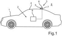
- a motor vehicle according to the invention includes a driver assistance system according to the invention.
- the motor vehicle is in particular formed as a passenger car.
- the motor vehicle is formed without rearview mirrors.
- rearview mirrors of the motor vehicle for example exterior mirrors and interior mirrors of the motor vehicle, are replaced by the antenna module with the camera.
- the antenna module which is preferably disposed on a roof of the motor vehicle, is therein in particular oriented such that the passage opening is formed in the rear wall of the antenna housing facing the rearward environmental region.
- the images of the rearward environmental region captured by the camera are presented on the display device for the driver, as already described.
- Fig. 2 shows the camera 7 of the antenna module 3 in an exploded representation.
- the camera 7 includes a camera objective 10 with a camera lens 11 and with an objective tube 12.
- the objective tube 12 is in particular cylindrically formed, wherein the lens 11 is disposed on the front side on the objective tube 12.
- the objective 10 has a retaining element 13 as well as a cap element 14.
- the camera 7 includes a camera housing 15, which has a rear housing 16 as well as a front housing 17.
- the rear housing 16 is in particular prismatic formed and covered on the front side by the front housing 17, which is in particular plate-shaped formed.
- electronics here illustrated as a circuit board 18 can be disposed.
- the circuit board 18 can be attached to the front housing 17 by means of fixing elements 19, for example screws.
- the circuit board 18 can for example have an image sensor and components for image processing of the images captured by the image sensor of the camera 7.
- the front housing 17 is also referred to as lens housing and serves for retaining the camera objective 10.
- the front housing 17 has a passage opening 20, in which the camera objective 10 can be disposed in certain areas.
- the retaining element 13 is disposed in the passage opening 20 such that the cap element 14 rests on a border 21 of the passage opening 20.
- the cap element 14 can be attached to the border 21 of the passage opening 20 by means of an adhesive 22 such that the objective 10 is retained on the front housing 17 and thereby on the camera housing 15.
- Fig. 3 shows an embodiment of the antenna module 3.
- the antenna module 3 has a GPS antenna 5a as well as a car-to-car communication antenna 5b as the at least one antenna 5.
- the antennas 5a, 5b are disposed in the interior of the antenna housing 6.
- the antenna housing 6 has a plate-shaped pedestal 23, on which the camera 7 and the antennas 5a, 5b are disposed, in particular attached.
- the plate-shaped pedestal 23 can be disposed and attached on the exterior trim part 4.
- the antenna housing 6 has a roof-like cover 24, which is here transparently illustrated.
- the roof-like cover 24 is in particular formed in the shape of a shark fin and forms a radome for the antennas 5a, 5b.
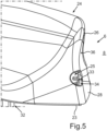
- a sealing element 27 is disposed in the gap such that the gap is closed and the antenna housing 6 is thereby sealed.
- the sealing element 27 is cylindrically formed and here completely surrounds the objective tube 12 along an outer circumference of the objective tube 12.
- the sealing element 27 can also extend over an entire length of the objective tube 12 and thereby completely surround an outer side of the objective tube 12.
- the sealing element 27 is for example manufactured of an elastic material or a polymer, in particular EPDM, and pressed into the gap. Otherwise stated, the sealing element 27 is radially compressed by the objective tube 12 and the housing wall 26 adjoining to the passage opening 25.
- the camera housing 15 does not have to be specifically sealed by for example providing a sealing element between the rear housing 16 and the front housing 17.
- the front housing 17 can be formed directly adjoining to the rear housing 16.
- the front housing 17 and the rear housing 16, thus the camera housing 15, can be formed of a shielding material, which shields the electronics in the camera housing 15 from the radiation of the antennas 5a, 5b without the shielding being interrupted for example by a sealing element between the rear housing 16 and the front housing 17.
- Fig. 4 shows the antenna module 3 without the cover 6 as well as without the sealing element 27.
- the camera 7 is disposed on the pedestal 23.
- a bearing surface 29 is on the pedestal 23, on which the GPS antenna 5a, the car-to-car communication antenna 5b, a radio antenna 5c and components 30 comprising electronics for the antennas 5a, 5b, 5c are disposed.
- the bearing surface 29 is here formed as a circuit board, a so-called antenna PCB (PCB- printed circuit board).
- the bearing surface 29 is for example connected to the pedestal 23.
- the pedestal 23 can be connected to the cover 24 not shown here by means of fixing elements 31, for example by screws.
- the antenna module 3 has an interface 32, via which the antenna PCB as well as the camera 7 can be connected to the controller of the driver assistance system 2, for example for transmitting data and/or for energy supply of the antenna PCB as well as the camera 7.
- the passage opening 25 is substantially formed as a cylindrical cavity.
- the housing wall 26 bounding the passage opening 25 has a predetermined wall thickness 33 thereto such that by an interface 34 between the housing opening 25 and the housing wall 26, thus by an inner side of a boundary of the cylindrical cavity, a sealing surface or a sealing area for the sealing element 27 is formed.
- the housing wall 26 can for example only be reinforced in the area adjoining to the passage opening 25.
- the sealing element 27 in particular has a length, which at least corresponds to the wall thickness 33 such that an outer side 35 (see Fig. 3 ) of the sealing element 27 forms a particularly large-area overlap area with the interface 34.
Landscapes
- Engineering & Computer Science (AREA)
- Remote Sensing (AREA)
- Mechanical Engineering (AREA)
- Details Of Aerials (AREA)
- Studio Devices (AREA)
- Fittings On The Vehicle Exterior For Carrying Loads, And Devices For Holding Or Mounting Articles (AREA)
Claims (12)
- Antennenmodul (3) für ein Kraftfahrzeug (1), umfassend zumindest eine Antenne (5, 5a, 5b, 5c) für ein Infotainment-System des Kraftfahrzeugs (1), ein Antennengehäuse (6) zum Befestigen an einem äußeren Verkleidungsteil (4) des Kraftfahrzeugs (1) und eine Kamera (7) mit einem Kameraobjektiv (10) zum Erfassen einer Umgebungsregion (8) des Kraftfahrzeugs (1), wobei die zumindest eine Antenne (5, 5a, 5b, 5c) in einem Innenraum des Antennengehäuses (6) angeordnet ist,
undwobei eine der einen oder mehreren Antennen eine Fahrzeug-zu-Fahrzeug-Kommunikationsantenne (5b) ist und die Kamera (7) im Inneren des Antennengehäuses (6) in bestimmten Bereichen angeordnet ist, wobei das Kameraobjektiv (10) in einer Durchgangsöffnung (25) einer Gehäusewand (26) des Antennengehäuses (6) entsprechend dem Kameraobjektiv (10) zumindest in bestimmten Bereichen angeordnet ist, und wobei das Antennenmodul (3) ein Abdichtungselement (27) zum Abdichten einer Lücke zwischen der Gehäusewand (26) angrenzend an die Durchgangsöffnung (25) und dem Kameraobjektiv (10) umfasst, wobei das Abdichtungselement (27) hohlzylindrisch ausgebildet istwobei die Kamera (7) ein Kameragehäuse (15) mit einem hinteren Gehäuse (16) für die Elektronik (18) der Kamera (7) und ein vorderes Gehäuse (17) zum Halten des Kameraobjektivs (10) umfasst, wobei das Kameragehäuse (15) im Inneren des Antennengehäuses (6) angeordnet ist und ein Abschirmungsmaterial zum Abschirmen der Elektronik der Kamera (7) gegen Strahlung der zumindest einen Antenne (5, 5a, 5b, 5c) umfasst. - Antennenmodul (3) nach Anspruch 1,
dadurch gekennzeichnet, dass
das Abdichtungselement (27) ein elastisches Material umfasst und in die Lücke zwischen der Gehäusewand (26) angrenzend an die Durchgangsöffnung (25) und dem Kameraobjektiv (10) gepresst wird. - Antennenmodul (3) nach Anspruch 1 oder 2,
dadurch gekennzeichnet, dass
das Abdichtungselement (27) Ethylen-Propylen-DienKautschuk als das elastische Material umfasst. - Antennenmodul (3) nach Anspruch 1,
dadurch gekennzeichnet, dass
ein Objektivtubus (12) des Kameraobjektivs (10) innerhalb des hohlzylindrischen Abdichtungselements (27) angeordnet ist, wobei das hohlzylindrische Abdichtungselement (27) den Objektivtubus (12) entlang einer Länge des Objektivtubus (12) zumindest in bestimmten Bereichen abdeckt. - Antennenmodul (3) nach Anspruch 4,
dadurch gekennzeichnet, dass
die Gehäusewand (26) eine vorbestimmte Wanddicke (33) zumindest in einem Bereich der Gehäusewand (26) angrenzend an die Durchgangsöffnung (25) aufweist, sodass die Durchgangsöffnung (25) als ein zylindrischer Hohlraum ausgebildet ist, und wobei eine Länge des hohlzylindrischen Abdichtungselements (27) zumindest der vorbestimmten Wanddicke (33) der Gehäusewand (26) entspricht. - Antennenmodul (3) nach einem der vorhergehenden Ansprüche,
dadurch gekennzeichnet, dass
eine Linse (11), angeordnet an einer Vorderseite des Kameraobjektivs (10), eine Vorderseite des Abdichtungselements (27) und eine Außenseite (36) der Gehäusewand (26) des Antennengehäuses (6) im Wesentlichen bündig angeordnet sind. - Antennenmodul (3) nach einem der vorhergehenden Ansprüche,
dadurch gekennzeichnet, dass
das Antennengehäuse (6) einen plattenförmigen Sockel (23) zum Anordnen am äußeren Verkleidungsteil (4) und eine dachförmige Abdeckung (24), die den Sockel (23) abdeckt, umfasst, wobei die Durchgangsöffnung (25) in einer hinteren Wand (28) der Abdeckung (24) ausgebildet ist. - Antennenmodul (3) nach einem der vorhergehenden Ansprüche,
dadurch gekennzeichnet, dass
das Antennenmodul (3) als ein Haifischflossenantennenmodul ausgebildet ist. - Fahrerassistenzsystem (2) für ein Kraftfahrzeug (1), mit einem Antennenmodul (3) nach einem der vorhergehenden Ansprüche.
- Kraftfahrzeug (1) mit einem Fahrerassistenzsystem (2) nach Anspruch 9.
- Kraftfahrzeug (1) nach Anspruch 10,
dadurch gekennzeichnet, dass
das Kraftfahrzeug (1) ohne Rückspiegel gebildet ist. - Kraftfahrzeug (1) nach Anspruch 10 oder 11,
dadurch gekennzeichnet, dass
das Antennenmodul (3) auf einem Dach (4) des Kraftfahrzeugs (1) angeordnet ist.
Applications Claiming Priority (2)
| Application Number | Priority Date | Filing Date | Title |
|---|---|---|---|
| DE102016100985.7A DE102016100985A1 (de) | 2016-01-21 | 2016-01-21 | Antennenmodul für ein Kraftfahrzeug, Fahrerassistenzsystem sowie Kraftfahrzeug |
| PCT/EP2017/051192 WO2017125552A1 (en) | 2016-01-21 | 2017-01-20 | Antenna module for a motor vehicle, driver assistance system as well as motor vehicle |
Publications (2)
| Publication Number | Publication Date |
|---|---|
| EP3405992A1 EP3405992A1 (de) | 2018-11-28 |
| EP3405992B1 true EP3405992B1 (de) | 2024-07-10 |
Family
ID=57909604
Family Applications (1)
| Application Number | Title | Priority Date | Filing Date |
|---|---|---|---|
| EP17701831.4A Active EP3405992B1 (de) | 2016-01-21 | 2017-01-20 | Antennenmodul für ein kraftfahrzeug, fahrerassistenzsystem sowie kraftfahrzeug |
Country Status (4)
| Country | Link |
|---|---|
| US (1) | US10707567B2 (de) |
| EP (1) | EP3405992B1 (de) |
| DE (1) | DE102016100985A1 (de) |
| WO (1) | WO2017125552A1 (de) |
Families Citing this family (14)
| Publication number | Priority date | Publication date | Assignee | Title |
|---|---|---|---|---|
| JP6567679B2 (ja) * | 2015-09-14 | 2019-08-28 | 株式会社ヨコオ | アンテナ装置 |
| US10340587B2 (en) * | 2016-09-13 | 2019-07-02 | Laird Technologies, Inc. | Antenna assemblies having sealed cameras |
| US10374297B2 (en) | 2017-09-12 | 2019-08-06 | Laird Technologies, Inc. | Antenna assemblies having sealed cameras |
| WO2019156138A1 (ja) * | 2018-02-08 | 2019-08-15 | 株式会社ヨコオ | 車載用アンテナ装置 |
| US11417947B2 (en) * | 2018-04-27 | 2022-08-16 | Yokowo Co., Ltd. | Antenna device for vehicle |
| FR3086750B1 (fr) * | 2018-09-28 | 2020-11-13 | Valeo Systemes Dessuyage | Dispositif de geolocalisation de vehicule automobile |
| NL2022163B1 (en) | 2018-12-10 | 2020-07-02 | Daf Trucks Nv | Wireless vehicle to vehicle communication system for mounting on a vehicle |
| DE102019214632B4 (de) * | 2019-09-25 | 2021-07-29 | Zf Friedrichshafen Ag | Kameraträger zur Befestigung an einem Fahrzeug und Verfahren zum Herstellen und zum Betreiben eines Kameraträgers |
| JP6802895B1 (ja) * | 2019-10-17 | 2020-12-23 | 原田工業株式会社 | 車両用外装装置 |
| RU204346U1 (ru) * | 2020-07-30 | 2021-05-21 | Общество с ограниченной ответственностью "Эй Ви Эй Системс" | Внешний антенный модуль с расширенным функционалом |
| CN213705325U (zh) * | 2020-11-17 | 2021-07-16 | 本田技研工业株式会社 | 传感器托架结构 |
| DE102022105422A1 (de) * | 2022-03-08 | 2023-09-14 | Connaught Electronics Ltd. | Fahrzeugkamera mit verbesserter Gehäuseausrichtung |
| EP4269177A1 (de) * | 2022-04-27 | 2023-11-01 | Grupo Antolin-Ingenieria, S.A. | Fahrzeugverkleidung mit kamera für fahrzeuge |
| CN115764247A (zh) * | 2022-05-06 | 2023-03-07 | 惠州市德赛西威汽车电子股份有限公司 | 一种集成摄像头装置的鲨鱼鳍天线 |
Citations (3)
| Publication number | Priority date | Publication date | Assignee | Title |
|---|---|---|---|---|
| KR20120000680U (ko) * | 2011-10-20 | 2012-02-01 | (주)아이머큐리 | 차량용 영상 카메라 |
| KR101251979B1 (ko) * | 2012-09-05 | 2013-04-08 | 주식회사 경오전자 | 자동차용 dmb안테나 겸용 블랙박스 후방카메라 |
| US20140158731A1 (en) * | 2012-12-10 | 2014-06-12 | Michael J. Squire | Vehicle camera mounting assembly |
Family Cites Families (31)
| Publication number | Priority date | Publication date | Assignee | Title |
|---|---|---|---|---|
| US5793420A (en) * | 1994-10-28 | 1998-08-11 | Schmidt; William P. | Video recording system for vehicle |
| AU2003290791A1 (en) * | 2002-11-14 | 2004-06-15 | Donnelly Corporation | Imaging system for vehicle |
| US7057500B1 (en) * | 2004-04-23 | 2006-06-06 | Belloso Gregorio M | Rear view monitoring system for motor vehicles |
| DE102005027089B4 (de) * | 2005-06-11 | 2013-03-21 | Daimler Ag | Profil zur Aufnahme eines Sensorbandes an einem Kraftfahrzeugstoßfänger sowie Stoßfänger |
| JP4497193B2 (ja) * | 2007-11-09 | 2010-07-07 | ソニー株式会社 | カメラ取り付け構造、カメラ取り付け方法および車両の外装パネル部品 |
| US20100129070A1 (en) * | 2008-11-21 | 2010-05-27 | Nissan Technical Center North America, Inc. | Rear view camera mounting on a vehicle |
| KR20110004565A (ko) * | 2009-07-08 | 2011-01-14 | 엘지전자 주식회사 | 가습부재 및 이를 구비한 가습유닛 |
| KR200455494Y1 (ko) * | 2009-10-30 | 2011-09-08 | 조부연 | 한 개 이상의 카메라모듈을 구성한 샤크 안테나 |
| KR101134305B1 (ko) * | 2010-04-12 | 2012-04-09 | (주)헤스코 | 자동차용 카메라 내장 샤크안테나 |
| JP5755015B2 (ja) * | 2010-06-06 | 2015-07-29 | 日東電工株式会社 | Epdm発泡体および粘着シール材 |
| DE102010064080A1 (de) | 2010-12-23 | 2012-06-28 | Robert Bosch Gmbh | Kameraabasiertes Fahrerassistenzsystem für ein Fahrzeug |
| EP2858755B1 (de) * | 2011-03-10 | 2017-09-20 | dlhBowles Inc. | Integriertes antriebssystem, düsenanordnung und fernsteuerungsverfahren zur reinigung der linse eines bildsensors |
| KR101052796B1 (ko) * | 2011-03-18 | 2011-07-29 | 박상옥 | 카메라가 설치된 차량용 안테나 |
| US9838653B2 (en) * | 2011-06-24 | 2017-12-05 | Gentex Corporation | Roof mounted imager module |
| US9871971B2 (en) * | 2011-08-02 | 2018-01-16 | Magma Electronics Inc. | Vehicle vision system with light baffling system |
| KR101155607B1 (ko) * | 2011-11-14 | 2012-06-13 | 최현준 | 카메라가 구비된 차량용 안테나 |
| US9849836B2 (en) * | 2014-04-24 | 2017-12-26 | Gentex Corporation | Roof mounted imager module |
| CN107206937B (zh) * | 2014-12-31 | 2020-03-13 | 金泰克斯公司 | 后视车辆照相机 |
| CN104979631A (zh) * | 2015-05-27 | 2015-10-14 | 泰州苏中天线集团有限公司 | 装有影像摄像头装置的鲨鱼鳍式天线 |
| DE102015210449B4 (de) * | 2015-06-08 | 2017-06-01 | Continental Teves Ag & Co. Ohg | Anordnung einer Kamera im Heckbereich eines Fahrzeugs, Kamera, Dachantenne und Fahrzeug |
| US9985343B2 (en) * | 2015-07-29 | 2018-05-29 | GM Global Technology Operations LLC | Optimal camera and antenna integration |
| JP6567679B2 (ja) * | 2015-09-14 | 2019-08-28 | 株式会社ヨコオ | アンテナ装置 |
| WO2017046972A1 (ja) * | 2015-09-14 | 2017-03-23 | 株式会社ヨコオ | 車載アンテナ装置 |
| US10351072B2 (en) * | 2015-11-05 | 2019-07-16 | Magna Electronics Inc. | Vehicle camera with modular construction |
| US10618474B2 (en) * | 2015-11-12 | 2020-04-14 | Connaught Electronics Ltd. | Sharkfin rf and camera integration |
| US9674414B1 (en) * | 2015-12-02 | 2017-06-06 | Bendix Commercial Vehicle Systems Llc | Camera module having compact camera subassembly insertable into the camera housing |
| US10129445B2 (en) * | 2016-03-04 | 2018-11-13 | Gentex Corporation | Roof mounted imager module |
| US10340587B2 (en) * | 2016-09-13 | 2019-07-02 | Laird Technologies, Inc. | Antenna assemblies having sealed cameras |
| JP6486314B2 (ja) * | 2016-10-28 | 2019-03-20 | 原田工業株式会社 | 車載用アンテナ装置 |
| KR102362139B1 (ko) * | 2017-03-30 | 2022-02-11 | 젠텍스 코포레이션 | 전환 가능한 이미저 렌즈 커버 |
| JP2019142401A (ja) * | 2018-02-22 | 2019-08-29 | 株式会社デンソー | 車載カメラ |
-
2016
- 2016-01-21 DE DE102016100985.7A patent/DE102016100985A1/de not_active Withdrawn
-
2017
- 2017-01-20 EP EP17701831.4A patent/EP3405992B1/de active Active
- 2017-01-20 US US15/411,011 patent/US10707567B2/en active Active
- 2017-01-20 WO PCT/EP2017/051192 patent/WO2017125552A1/en not_active Ceased
Patent Citations (3)
| Publication number | Priority date | Publication date | Assignee | Title |
|---|---|---|---|---|
| KR20120000680U (ko) * | 2011-10-20 | 2012-02-01 | (주)아이머큐리 | 차량용 영상 카메라 |
| KR101251979B1 (ko) * | 2012-09-05 | 2013-04-08 | 주식회사 경오전자 | 자동차용 dmb안테나 겸용 블랙박스 후방카메라 |
| US20140158731A1 (en) * | 2012-12-10 | 2014-06-12 | Michael J. Squire | Vehicle camera mounting assembly |
Non-Patent Citations (1)
| Title |
|---|
| ANONYMOUS: "Power steering - Wikipedia", 13 May 2014 (2014-05-13), XP055448325, Retrieved from the Internet <URL:https://en.wikipedia.org/w/index.php?title=Power_steering&oldid=608342086> [retrieved on 20180206] * |
Also Published As
| Publication number | Publication date |
|---|---|
| EP3405992A1 (de) | 2018-11-28 |
| US10707567B2 (en) | 2020-07-07 |
| US20170214130A1 (en) | 2017-07-27 |
| DE102016100985A1 (de) | 2017-07-27 |
| WO2017125552A1 (en) | 2017-07-27 |
Similar Documents
| Publication | Publication Date | Title |
|---|---|---|
| EP3405992B1 (de) | Antennenmodul für ein kraftfahrzeug, fahrerassistenzsystem sowie kraftfahrzeug | |
| US10073163B2 (en) | Control device | |
| JP6883634B2 (ja) | 車載アンテナ装置 | |
| US10033934B2 (en) | Vehicle vision system with exterior viewing camera | |
| US11202039B2 (en) | Indicia and camera assembly for a vehicle | |
| CN1284273C (zh) | 机动二轮车的天线配置构造 | |
| KR101498804B1 (ko) | 차량용 미러 대체 시스템 | |
| US20180037171A1 (en) | Concealed mounting for autonomous vehicle sensor | |
| CN106255618A (zh) | 具有无侧后视镜的后视装置的机动车 | |
| WO2013123161A1 (en) | Vehicle vision system with light baffling system | |
| CN112533795B (zh) | 用于保持传感器单元的保持装置以及保持装置的布置系统 | |
| CN105449337B (zh) | 噪声去除机构 | |
| CN105774678A (zh) | 可变结构构件覆盖 | |
| US20200366821A1 (en) | Roof Antenna Of A Vehicle Having A Reversing Camera | |
| JP2017073751A (ja) | 車載カメラ及び車両 | |
| CN113382889A (zh) | 用于设置在机动车的前端部或后端部中的结构单元 | |
| CN111083319B (zh) | 照相机装置 | |
| JP4718243B2 (ja) | コネクタユニット、車載用デジタルカメラ、車載カメラ付きドアミラー | |
| US10596979B2 (en) | Device for capturing optical information | |
| WO2017125477A1 (en) | Antenna module for a motor vehicle, driver assistance system as well as motor vehicle | |
| US20080278581A1 (en) | Vehicle-Mounted Camera System | |
| US20190179215A1 (en) | Camera for a motor vehicle, comprising an integrally formed housing top part and a lens carrier, as well as motor vehicle and method for manufacturing a camera for a motor vehicle | |
| JP6455357B2 (ja) | 車載機器の取付構造 | |
| CN106553592B (zh) | 用于安装车辆的后置摄像头的结构 | |
| US9866736B2 (en) | Device having a camera unit and a double-walled housing |
Legal Events
| Date | Code | Title | Description |
|---|---|---|---|
| STAA | Information on the status of an ep patent application or granted ep patent |
Free format text: STATUS: UNKNOWN |
|
| STAA | Information on the status of an ep patent application or granted ep patent |
Free format text: STATUS: THE INTERNATIONAL PUBLICATION HAS BEEN MADE |
|
| PUAI | Public reference made under article 153(3) epc to a published international application that has entered the european phase |
Free format text: ORIGINAL CODE: 0009012 |
|
| STAA | Information on the status of an ep patent application or granted ep patent |
Free format text: STATUS: REQUEST FOR EXAMINATION WAS MADE |
|
| 17P | Request for examination filed |
Effective date: 20180625 |
|
| AK | Designated contracting states |
Kind code of ref document: A1 Designated state(s): AL AT BE BG CH CY CZ DE DK EE ES FI FR GB GR HR HU IE IS IT LI LT LU LV MC MK MT NL NO PL PT RO RS SE SI SK SM TR |
|
| AX | Request for extension of the european patent |
Extension state: BA ME |
|
| RIN1 | Information on inventor provided before grant (corrected) |
Inventor name: GRIMES, CAROL Inventor name: HEHIR, COLIN PATRICK |
|
| DAV | Request for validation of the european patent (deleted) | ||
| DAX | Request for extension of the european patent (deleted) | ||
| STAA | Information on the status of an ep patent application or granted ep patent |
Free format text: STATUS: EXAMINATION IS IN PROGRESS |
|
| 17Q | First examination report despatched |
Effective date: 20200218 |
|
| P01 | Opt-out of the competence of the unified patent court (upc) registered |
Effective date: 20230528 |
|
| GRAP | Despatch of communication of intention to grant a patent |
Free format text: ORIGINAL CODE: EPIDOSNIGR1 |
|
| STAA | Information on the status of an ep patent application or granted ep patent |
Free format text: STATUS: GRANT OF PATENT IS INTENDED |
|
| RIC1 | Information provided on ipc code assigned before grant |
Ipc: B60R 11/00 20060101ALN20240115BHEP Ipc: H01Q 1/42 20060101ALN20240115BHEP Ipc: B60R 11/04 20060101ALI20240115BHEP Ipc: H01Q 1/32 20060101ALI20240115BHEP Ipc: H01Q 1/12 20060101AFI20240115BHEP |
|
| INTG | Intention to grant announced |
Effective date: 20240206 |
|
| GRAS | Grant fee paid |
Free format text: ORIGINAL CODE: EPIDOSNIGR3 |
|
| GRAA | (expected) grant |
Free format text: ORIGINAL CODE: 0009210 |
|
| STAA | Information on the status of an ep patent application or granted ep patent |
Free format text: STATUS: THE PATENT HAS BEEN GRANTED |
|
| AK | Designated contracting states |
Kind code of ref document: B1 Designated state(s): AL AT BE BG CH CY CZ DE DK EE ES FI FR GB GR HR HU IE IS IT LI LT LU LV MC MK MT NL NO PL PT RO RS SE SI SK SM TR |
|
| REG | Reference to a national code |
Ref country code: CH Ref legal event code: EP |
|
| REG | Reference to a national code |
Ref country code: DE Ref legal event code: R096 Ref document number: 602017083163 Country of ref document: DE |
|
| REG | Reference to a national code |
Ref country code: LT Ref legal event code: MG9D |
|
| REG | Reference to a national code |
Ref country code: NL Ref legal event code: MP Effective date: 20240710 |
|
| PG25 | Lapsed in a contracting state [announced via postgrant information from national office to epo] |
Ref country code: PT Free format text: LAPSE BECAUSE OF FAILURE TO SUBMIT A TRANSLATION OF THE DESCRIPTION OR TO PAY THE FEE WITHIN THE PRESCRIBED TIME-LIMIT Effective date: 20241111 |
|
| REG | Reference to a national code |
Ref country code: AT Ref legal event code: MK05 Ref document number: 1702868 Country of ref document: AT Kind code of ref document: T Effective date: 20240710 |
|
| PG25 | Lapsed in a contracting state [announced via postgrant information from national office to epo] |
Ref country code: NL Free format text: LAPSE BECAUSE OF FAILURE TO SUBMIT A TRANSLATION OF THE DESCRIPTION OR TO PAY THE FEE WITHIN THE PRESCRIBED TIME-LIMIT Effective date: 20240710 |
|
| PG25 | Lapsed in a contracting state [announced via postgrant information from national office to epo] |
Ref country code: PT Free format text: LAPSE BECAUSE OF FAILURE TO SUBMIT A TRANSLATION OF THE DESCRIPTION OR TO PAY THE FEE WITHIN THE PRESCRIBED TIME-LIMIT Effective date: 20241111 Ref country code: NL Free format text: LAPSE BECAUSE OF FAILURE TO SUBMIT A TRANSLATION OF THE DESCRIPTION OR TO PAY THE FEE WITHIN THE PRESCRIBED TIME-LIMIT Effective date: 20240710 |
|
| PG25 | Lapsed in a contracting state [announced via postgrant information from national office to epo] |
Ref country code: NO Free format text: LAPSE BECAUSE OF FAILURE TO SUBMIT A TRANSLATION OF THE DESCRIPTION OR TO PAY THE FEE WITHIN THE PRESCRIBED TIME-LIMIT Effective date: 20241010 |
|
| PG25 | Lapsed in a contracting state [announced via postgrant information from national office to epo] |
Ref country code: GR Free format text: LAPSE BECAUSE OF FAILURE TO SUBMIT A TRANSLATION OF THE DESCRIPTION OR TO PAY THE FEE WITHIN THE PRESCRIBED TIME-LIMIT Effective date: 20241011 Ref country code: PL Free format text: LAPSE BECAUSE OF FAILURE TO SUBMIT A TRANSLATION OF THE DESCRIPTION OR TO PAY THE FEE WITHIN THE PRESCRIBED TIME-LIMIT Effective date: 20240710 Ref country code: FI Free format text: LAPSE BECAUSE OF FAILURE TO SUBMIT A TRANSLATION OF THE DESCRIPTION OR TO PAY THE FEE WITHIN THE PRESCRIBED TIME-LIMIT Effective date: 20240710 |
|
| PG25 | Lapsed in a contracting state [announced via postgrant information from national office to epo] |
Ref country code: BG Free format text: LAPSE BECAUSE OF FAILURE TO SUBMIT A TRANSLATION OF THE DESCRIPTION OR TO PAY THE FEE WITHIN THE PRESCRIBED TIME-LIMIT Effective date: 20240710 |
|
| PG25 | Lapsed in a contracting state [announced via postgrant information from national office to epo] |
Ref country code: LV Free format text: LAPSE BECAUSE OF FAILURE TO SUBMIT A TRANSLATION OF THE DESCRIPTION OR TO PAY THE FEE WITHIN THE PRESCRIBED TIME-LIMIT Effective date: 20240710 |
|
| PG25 | Lapsed in a contracting state [announced via postgrant information from national office to epo] |
Ref country code: IS Free format text: LAPSE BECAUSE OF FAILURE TO SUBMIT A TRANSLATION OF THE DESCRIPTION OR TO PAY THE FEE WITHIN THE PRESCRIBED TIME-LIMIT Effective date: 20241110 Ref country code: AT Free format text: LAPSE BECAUSE OF FAILURE TO SUBMIT A TRANSLATION OF THE DESCRIPTION OR TO PAY THE FEE WITHIN THE PRESCRIBED TIME-LIMIT Effective date: 20240710 |
|
| PG25 | Lapsed in a contracting state [announced via postgrant information from national office to epo] |
Ref country code: HR Free format text: LAPSE BECAUSE OF FAILURE TO SUBMIT A TRANSLATION OF THE DESCRIPTION OR TO PAY THE FEE WITHIN THE PRESCRIBED TIME-LIMIT Effective date: 20240710 |
|
| PG25 | Lapsed in a contracting state [announced via postgrant information from national office to epo] |
Ref country code: ES Free format text: LAPSE BECAUSE OF FAILURE TO SUBMIT A TRANSLATION OF THE DESCRIPTION OR TO PAY THE FEE WITHIN THE PRESCRIBED TIME-LIMIT Effective date: 20240710 Ref country code: RS Free format text: LAPSE BECAUSE OF FAILURE TO SUBMIT A TRANSLATION OF THE DESCRIPTION OR TO PAY THE FEE WITHIN THE PRESCRIBED TIME-LIMIT Effective date: 20241010 |
|
| PG25 | Lapsed in a contracting state [announced via postgrant information from national office to epo] |
Ref country code: RS Free format text: LAPSE BECAUSE OF FAILURE TO SUBMIT A TRANSLATION OF THE DESCRIPTION OR TO PAY THE FEE WITHIN THE PRESCRIBED TIME-LIMIT Effective date: 20241010 Ref country code: PL Free format text: LAPSE BECAUSE OF FAILURE TO SUBMIT A TRANSLATION OF THE DESCRIPTION OR TO PAY THE FEE WITHIN THE PRESCRIBED TIME-LIMIT Effective date: 20240710 Ref country code: NO Free format text: LAPSE BECAUSE OF FAILURE TO SUBMIT A TRANSLATION OF THE DESCRIPTION OR TO PAY THE FEE WITHIN THE PRESCRIBED TIME-LIMIT Effective date: 20241010 Ref country code: LV Free format text: LAPSE BECAUSE OF FAILURE TO SUBMIT A TRANSLATION OF THE DESCRIPTION OR TO PAY THE FEE WITHIN THE PRESCRIBED TIME-LIMIT Effective date: 20240710 Ref country code: IS Free format text: LAPSE BECAUSE OF FAILURE TO SUBMIT A TRANSLATION OF THE DESCRIPTION OR TO PAY THE FEE WITHIN THE PRESCRIBED TIME-LIMIT Effective date: 20241110 Ref country code: HR Free format text: LAPSE BECAUSE OF FAILURE TO SUBMIT A TRANSLATION OF THE DESCRIPTION OR TO PAY THE FEE WITHIN THE PRESCRIBED TIME-LIMIT Effective date: 20240710 Ref country code: GR Free format text: LAPSE BECAUSE OF FAILURE TO SUBMIT A TRANSLATION OF THE DESCRIPTION OR TO PAY THE FEE WITHIN THE PRESCRIBED TIME-LIMIT Effective date: 20241011 Ref country code: FI Free format text: LAPSE BECAUSE OF FAILURE TO SUBMIT A TRANSLATION OF THE DESCRIPTION OR TO PAY THE FEE WITHIN THE PRESCRIBED TIME-LIMIT Effective date: 20240710 Ref country code: ES Free format text: LAPSE BECAUSE OF FAILURE TO SUBMIT A TRANSLATION OF THE DESCRIPTION OR TO PAY THE FEE WITHIN THE PRESCRIBED TIME-LIMIT Effective date: 20240710 Ref country code: BG Free format text: LAPSE BECAUSE OF FAILURE TO SUBMIT A TRANSLATION OF THE DESCRIPTION OR TO PAY THE FEE WITHIN THE PRESCRIBED TIME-LIMIT Effective date: 20240710 Ref country code: AT Free format text: LAPSE BECAUSE OF FAILURE TO SUBMIT A TRANSLATION OF THE DESCRIPTION OR TO PAY THE FEE WITHIN THE PRESCRIBED TIME-LIMIT Effective date: 20240710 |
|
| REG | Reference to a national code |
Ref country code: DE Ref legal event code: R097 Ref document number: 602017083163 Country of ref document: DE |
|
| PG25 | Lapsed in a contracting state [announced via postgrant information from national office to epo] |
Ref country code: DK Free format text: LAPSE BECAUSE OF FAILURE TO SUBMIT A TRANSLATION OF THE DESCRIPTION OR TO PAY THE FEE WITHIN THE PRESCRIBED TIME-LIMIT Effective date: 20240710 Ref country code: SM Free format text: LAPSE BECAUSE OF FAILURE TO SUBMIT A TRANSLATION OF THE DESCRIPTION OR TO PAY THE FEE WITHIN THE PRESCRIBED TIME-LIMIT Effective date: 20240710 Ref country code: RO Free format text: LAPSE BECAUSE OF FAILURE TO SUBMIT A TRANSLATION OF THE DESCRIPTION OR TO PAY THE FEE WITHIN THE PRESCRIBED TIME-LIMIT Effective date: 20240710 |
|
| PG25 | Lapsed in a contracting state [announced via postgrant information from national office to epo] |
Ref country code: EE Free format text: LAPSE BECAUSE OF FAILURE TO SUBMIT A TRANSLATION OF THE DESCRIPTION OR TO PAY THE FEE WITHIN THE PRESCRIBED TIME-LIMIT Effective date: 20240710 |
|
| PG25 | Lapsed in a contracting state [announced via postgrant information from national office to epo] |
Ref country code: CZ Free format text: LAPSE BECAUSE OF FAILURE TO SUBMIT A TRANSLATION OF THE DESCRIPTION OR TO PAY THE FEE WITHIN THE PRESCRIBED TIME-LIMIT Effective date: 20240710 |
|
| PG25 | Lapsed in a contracting state [announced via postgrant information from national office to epo] |
Ref country code: IT Free format text: LAPSE BECAUSE OF FAILURE TO SUBMIT A TRANSLATION OF THE DESCRIPTION OR TO PAY THE FEE WITHIN THE PRESCRIBED TIME-LIMIT Effective date: 20240710 Ref country code: SK Free format text: LAPSE BECAUSE OF FAILURE TO SUBMIT A TRANSLATION OF THE DESCRIPTION OR TO PAY THE FEE WITHIN THE PRESCRIBED TIME-LIMIT Effective date: 20240710 |
|
| PLBE | No opposition filed within time limit |
Free format text: ORIGINAL CODE: 0009261 |
|
| STAA | Information on the status of an ep patent application or granted ep patent |
Free format text: STATUS: NO OPPOSITION FILED WITHIN TIME LIMIT |
|
| 26N | No opposition filed |
Effective date: 20250411 |
|
| REG | Reference to a national code |
Ref country code: CH Ref legal event code: PL |
|
| PG25 | Lapsed in a contracting state [announced via postgrant information from national office to epo] |
Ref country code: SE Free format text: LAPSE BECAUSE OF FAILURE TO SUBMIT A TRANSLATION OF THE DESCRIPTION OR TO PAY THE FEE WITHIN THE PRESCRIBED TIME-LIMIT Effective date: 20240710 |
|
| PG25 | Lapsed in a contracting state [announced via postgrant information from national office to epo] |
Ref country code: LU Free format text: LAPSE BECAUSE OF NON-PAYMENT OF DUE FEES Effective date: 20250120 Ref country code: MC Free format text: LAPSE BECAUSE OF FAILURE TO SUBMIT A TRANSLATION OF THE DESCRIPTION OR TO PAY THE FEE WITHIN THE PRESCRIBED TIME-LIMIT Effective date: 20240710 |
|
| PG25 | Lapsed in a contracting state [announced via postgrant information from national office to epo] |
Ref country code: BE Free format text: LAPSE BECAUSE OF NON-PAYMENT OF DUE FEES Effective date: 20250131 |
|
| PG25 | Lapsed in a contracting state [announced via postgrant information from national office to epo] |
Ref country code: CH Free format text: LAPSE BECAUSE OF NON-PAYMENT OF DUE FEES Effective date: 20250131 |
|
| REG | Reference to a national code |
Ref country code: BE Ref legal event code: MM Effective date: 20250131 |
|
| PG25 | Lapsed in a contracting state [announced via postgrant information from national office to epo] |
Ref country code: IE Free format text: LAPSE BECAUSE OF NON-PAYMENT OF DUE FEES Effective date: 20250120 |
|
| PGFP | Annual fee paid to national office [announced via postgrant information from national office to epo] |
Ref country code: GB Payment date: 20260127 Year of fee payment: 10 |
|
| PGFP | Annual fee paid to national office [announced via postgrant information from national office to epo] |
Ref country code: DE Payment date: 20260114 Year of fee payment: 10 |
|
| PGFP | Annual fee paid to national office [announced via postgrant information from national office to epo] |
Ref country code: FR Payment date: 20260128 Year of fee payment: 10 |