EP3405941B1 - Method for attaching marking labels to a plurality of electrical devices which can be arranged on a support rail - Google Patents
Method for attaching marking labels to a plurality of electrical devices which can be arranged on a support rail Download PDFInfo
- Publication number
- EP3405941B1 EP3405941B1 EP17705017.6A EP17705017A EP3405941B1 EP 3405941 B1 EP3405941 B1 EP 3405941B1 EP 17705017 A EP17705017 A EP 17705017A EP 3405941 B1 EP3405941 B1 EP 3405941B1
- Authority
- EP
- European Patent Office
- Prior art keywords
- marking
- electrical devices
- strip
- plates
- electrical
- Prior art date
- Legal status (The legal status is an assumption and is not a legal conclusion. Google has not performed a legal analysis and makes no representation as to the accuracy of the status listed.)
- Active
Links
- 238000000034 method Methods 0.000 title claims description 21
- 238000000926 separation method Methods 0.000 claims description 3
- 239000000463 material Substances 0.000 description 20
- 239000010410 layer Substances 0.000 description 19
- 238000002372 labelling Methods 0.000 description 17
- 239000003550 marker Substances 0.000 description 10
- 239000012790 adhesive layer Substances 0.000 description 9
- 238000010330 laser marking Methods 0.000 description 7
- 230000001427 coherent effect Effects 0.000 description 6
- 239000000853 adhesive Substances 0.000 description 5
- 230000001070 adhesive effect Effects 0.000 description 5
- 239000002356 single layer Substances 0.000 description 4
- 239000004020 conductor Substances 0.000 description 3
- 238000003780 insertion Methods 0.000 description 2
- 230000037431 insertion Effects 0.000 description 2
- 229920001707 polybutylene terephthalate Polymers 0.000 description 2
- 229920000515 polycarbonate Polymers 0.000 description 2
- 239000004417 polycarbonate Substances 0.000 description 2
- 230000003313 weakening effect Effects 0.000 description 2
- OKTJSMMVPCPJKN-UHFFFAOYSA-N Carbon Chemical compound [C] OKTJSMMVPCPJKN-UHFFFAOYSA-N 0.000 description 1
- NIXOWILDQLNWCW-UHFFFAOYSA-N acrylic acid group Chemical group C(C=C)(=O)O NIXOWILDQLNWCW-UHFFFAOYSA-N 0.000 description 1
- 239000000654 additive Substances 0.000 description 1
- MTAZNLWOLGHBHU-UHFFFAOYSA-N butadiene-styrene rubber Chemical compound C=CC=C.C=CC1=CC=CC=C1 MTAZNLWOLGHBHU-UHFFFAOYSA-N 0.000 description 1
- 229910052799 carbon Inorganic materials 0.000 description 1
- 238000003763 carbonization Methods 0.000 description 1
- 239000003086 colorant Substances 0.000 description 1
- 239000003292 glue Substances 0.000 description 1
- 239000013067 intermediate product Substances 0.000 description 1
- -1 polybutylene terephthalate Polymers 0.000 description 1
- 230000001681 protective effect Effects 0.000 description 1
- 230000001960 triggered effect Effects 0.000 description 1
Images


Classifications
-
- B—PERFORMING OPERATIONS; TRANSPORTING
- B41—PRINTING; LINING MACHINES; TYPEWRITERS; STAMPS
- B41M—PRINTING, DUPLICATING, MARKING, OR COPYING PROCESSES; COLOUR PRINTING
- B41M5/00—Duplicating or marking methods; Sheet materials for use therein
- B41M5/24—Ablative recording, e.g. by burning marks; Spark recording
-
- B—PERFORMING OPERATIONS; TRANSPORTING
- B41—PRINTING; LINING MACHINES; TYPEWRITERS; STAMPS
- B41J—TYPEWRITERS; SELECTIVE PRINTING MECHANISMS, i.e. MECHANISMS PRINTING OTHERWISE THAN FROM A FORME; CORRECTION OF TYPOGRAPHICAL ERRORS
- B41J2/00—Typewriters or selective printing mechanisms characterised by the printing or marking process for which they are designed
- B41J2/435—Typewriters or selective printing mechanisms characterised by the printing or marking process for which they are designed characterised by selective application of radiation to a printing material or impression-transfer material
- B41J2/44—Typewriters or selective printing mechanisms characterised by the printing or marking process for which they are designed characterised by selective application of radiation to a printing material or impression-transfer material using single radiation source per colour, e.g. lighting beams or shutter arrangements
- B41J2/442—Typewriters or selective printing mechanisms characterised by the printing or marking process for which they are designed characterised by selective application of radiation to a printing material or impression-transfer material using single radiation source per colour, e.g. lighting beams or shutter arrangements using lasers
-
- B—PERFORMING OPERATIONS; TRANSPORTING
- B41—PRINTING; LINING MACHINES; TYPEWRITERS; STAMPS
- B41J—TYPEWRITERS; SELECTIVE PRINTING MECHANISMS, i.e. MECHANISMS PRINTING OTHERWISE THAN FROM A FORME; CORRECTION OF TYPOGRAPHICAL ERRORS
- B41J3/00—Typewriters or selective printing or marking mechanisms characterised by the purpose for which they are constructed
- B41J3/407—Typewriters or selective printing or marking mechanisms characterised by the purpose for which they are constructed for marking on special material
- B41J3/4073—Printing on three-dimensional objects not being in sheet or web form, e.g. spherical or cubic objects
-
- B—PERFORMING OPERATIONS; TRANSPORTING
- B41—PRINTING; LINING MACHINES; TYPEWRITERS; STAMPS
- B41M—PRINTING, DUPLICATING, MARKING, OR COPYING PROCESSES; COLOUR PRINTING
- B41M5/00—Duplicating or marking methods; Sheet materials for use therein
- B41M5/26—Thermography ; Marking by high energetic means, e.g. laser otherwise than by burning, and characterised by the material used
-
- G—PHYSICS
- G09—EDUCATION; CRYPTOGRAPHY; DISPLAY; ADVERTISING; SEALS
- G09F—DISPLAYING; ADVERTISING; SIGNS; LABELS OR NAME-PLATES; SEALS
- G09F3/00—Labels, tag tickets, or similar identification or indication means; Seals; Postage or like stamps
-
- G—PHYSICS
- G09—EDUCATION; CRYPTOGRAPHY; DISPLAY; ADVERTISING; SEALS
- G09F—DISPLAYING; ADVERTISING; SIGNS; LABELS OR NAME-PLATES; SEALS
- G09F3/00—Labels, tag tickets, or similar identification or indication means; Seals; Postage or like stamps
- G09F3/08—Fastening or securing by means not forming part of the material of the label itself
- G09F3/18—Casings, frames or enclosures for labels
- G09F3/20—Casings, frames or enclosures for labels for adjustable, removable, or interchangeable labels
- G09F3/205—Casings, frames or enclosures for labels for adjustable, removable, or interchangeable labels specially adapted for electric cables, pipes or the like
-
- G—PHYSICS
- G09—EDUCATION; CRYPTOGRAPHY; DISPLAY; ADVERTISING; SEALS
- G09F—DISPLAYING; ADVERTISING; SIGNS; LABELS OR NAME-PLATES; SEALS
- G09F7/00—Signs, name or number plates, letters, numerals, or symbols; Panels or boards
-
- G—PHYSICS
- G09—EDUCATION; CRYPTOGRAPHY; DISPLAY; ADVERTISING; SEALS
- G09F—DISPLAYING; ADVERTISING; SIGNS; LABELS OR NAME-PLATES; SEALS
- G09F7/00—Signs, name or number plates, letters, numerals, or symbols; Panels or boards
- G09F7/02—Signs, plates, panels or boards using readily-detachable elements bearing or forming symbols
- G09F7/08—Signs, plates, panels or boards using readily-detachable elements bearing or forming symbols the elements being secured or adapted to be secured by means of grooves, rails, or slits
- G09F7/10—Signs, plates, panels or boards using readily-detachable elements bearing or forming symbols the elements being secured or adapted to be secured by means of grooves, rails, or slits and slideably mounted
Definitions
- the invention relates to a method for attaching marker plates to a plurality of electrical devices that can be arranged on a mounting rail.
- Such a method is used to attach marking plates to a plurality of electrical devices that can be arranged on a mounting rail and each have a marking field on which a marking plate that can be inscribed can be attached.
- the electrical devices are lined up along a longitudinal direction to provide an assembly in such a way that the marking fields of the electrical devices adjoin one another along the longitudinal direction and form a continuous row extending along the longitudinal direction.
- Such an assembly is, for example, from DE 10 2013 112 789 A1 known and in particular comprises a plurality of electrical devices in the form of so-called terminal blocks.
- the electrical devices are arranged on an auxiliary transport device in the form of a carrier tape and can be transported in such a preassembled state and used in a machine for equipping a carrier rail.
- Electrical devices that can be attached to a mounting rail for example terminal blocks or electronic devices that are used to carry out control or automation functions, for example in the context of an industrial plant, can for example be combined with one another in a control cabinet and for this purpose mounted on one in the control cabinet Mounting rail can be attached to provide an electrical system within the control cabinet.
- marking plates are attached to the electrical devices. While machines are now used to equip mounting rails, for example with terminal blocks, such as those from the DE 10 2010 047 369 A1 are known, the identification of the electrical devices attached to a mounting rail is often still done manually by already labeled marking plates being attached to the electrical devices. This is cumbersome and can also be prone to errors.
- a device for mounting an identification plate in a groove-shaped latching recess of a terminal block is known.
- a labeled identification plate can be pressed into an associated latching recess of a terminal block by means of an assembly stamp.
- Another device for marking switchgear terminal blocks is from the DE-U 1 857 546 known.
- the DE 203 03 475 U1 describes that terminal blocks that form a labeling level on a level without lateral offset can be marked together with a coherent labeling strip.
- the object of the present invention is to provide a method for attaching marking plates to electrical devices, as well as a marking strip and an assembly of electrical devices that allow electrical devices, for example terminal blocks, to be labeled in a simple, automatable manner.
- the presented method represents a departure from conventionally known methods for labeling electrical devices that are to be arranged on a mounting rail.
- electrical devices to which markable labels are to be attached are first grouped into an assembly and for this purpose lined up so that marking fields of the electrical devices adjoin one another along a longitudinal direction and form a continuous row extending along the longitudinal direction.
- a (coherent) marking strip can then be attached to this row, which has a plurality of marking plates that can be written on.
- the marking plates are attached to the row of electrical devices in such a way that one (or more) marking plates are assigned to each marking field of an electrical device. After the marking strip has been applied, the marking plates are separated so that one or more marking plates remain on the marking field of each electrical device.
- the marking plates arranged on the marking fields of the electrical devices can be inscribed by means of a laser inscription device. This can be done before or after the electrical devices are attached to a mounting rail.
- marking plates are initially attached to a plurality of electrical devices in a manner that is easy to automate, and only then are the marking plates inscribed by a laser inscription device.
- the labeling can take place, for example, when the electrical devices are already attached to a mounting rail and combined with other electrical devices, for which purpose a laser beam from the laser labeling device is controlled in such a way that a suitable, individual label is applied to the individual marking plates of the electrical devices in a targeted manner .
- the electrical devices are thus initially provided with unlabeled marking labels and can thus be delivered and attached to a mounting rail. First after placing it on the mounting rail, the labeling takes place, which can reduce the susceptibility to errors when labeling.
- the marking strip can preferably be glued onto the electrical devices along the row of marking fields.
- the marking strip on the marking plates can have an adhesive layer which forms an adhesive connection with the electrical devices and via which the marking plates are individually attached to the respectively assigned marking fields of the electrical devices.
- the marking fields of the electrical devices can be provided on recesses in the electrical devices.
- the recesses of the electrical devices form a groove which extends longitudinally along the longitudinal direction and into which the marking strip can be inserted in order to fasten the marking strip to the electrical devices.
- the marking fields to which the marking strips of the marking strips are to be attached can be formed, for example, on the bottoms of the recesses of the electrical devices, it being conceivable and possible for the recesses to each have undercuts on the side edges that create a Establish a positive connection and thus hold the marking strip in the groove with a positive fit.
- the marking strip can have a trapezoidal shape which tapers conically in the attachment direction and which facilitates the insertion of the marking strip into the groove.
- the electrical devices for example in the form of terminal blocks, can be lined up next to one another, for example on a carrier tape extending along the longitudinal direction.
- the carrier tape provides an auxiliary transport device, as shown in DE 10 2013 112 789 A1 is described.
- a network of electrical devices is created that can be gripped by a user and used, for example, in a machine for equipping a mounting rail.
- the electrical devices, for example terminal blocks can have the same design, but can also be of different designs, as long as the marking fields of the individual electrical devices connect to one another and form a continuous row to which the marking strip can be attached.
- the marking strip is in the form of a continuous strip in which the marking plates can be connected to one another in different ways.
- the marking plates can be connected to one another via a fixing strip in the initial state, the fixing strip being detachable from the marking plates in order to separate the marking plates.
- the marking strip can thus - in the case of marking plates connected to one another via the fixing strip - be attached to the row of marking fields of the electrical devices in order to glue the marking plates to the electrical devices, for example. If the marking strip is arranged on the electrical devices, the fixing strip can be peeled off, the marking plates remaining on the electrical devices and the electrical devices thus being equipped with marking plates that can be written on.
- the marking plates can also be connected to one another in one piece in the initial state.
- the marking plates can be separated from one another, for example by separating the marking plates from one another along separating lines formed on the marking strips.
- the dividing lines can be formed on the marking strip, for example, by targeted material weakening, for example by perforation or by material thinning.
- Adjacent marking plates can be detached from one another along the dividing lines, which can be done automatically using a suitable tool or even when the electrical devices are separated from one another.
- the electrical devices of the assembly have been equipped with marking plates by means of the described method, then some or all of the electrical devices can be attached to a mounting rail in order to equip the mounting rail and in this way provide an electrical system, for example within a control cabinet.
- an electrical device can be removed from the assembly of the electrical devices in a row and attached to the mounting rail.
- the marking plate of the electrical device that has been removed and attached to the mounting rail can then be labeled with a laser labeling device in order to identify the electrical device, for example, in its function and / or in its connections.
- Very different electrical devices of very different designs can be combined with one another on the mounting rail. Marking plates of the different electrical devices can be labeled via the laser labeling device, which can be done with electrical devices already arranged on the mounting rail.
- a marking strip for fastening to a row of marking fields of a plurality of lined up electrical devices that can be arranged on a mounting rail has a plurality of marking plates that are connected to one another in an initial state, are to be separated and can be labeled with a laser marking device. Because the marking strip as a whole can be attached to the row of marking fields of the side-by-side electrical devices, the electrical devices can be provided with marking plates in one work step, which can then be labeled using laser inscription.
- Each marking label of the marking strip can, for example, have an adhesive layer for attachment to a marking field of an electrical device. Each marking plate can be attached to an assigned marking field of an electrical device via the adhesive layer and thus glued to the marking field.
- the marking plates of the marking strip can be written on using a laser marking device.
- a laser beam can be directed onto a marking plate in order to apply a predetermined, individual identification to the marking plate in this way.
- the marking plates can have a single-layer basic structure of a laser-inscribable material. In this case, laser marking changes the material itself so that a color change is triggered in the material.
- a multi-layer basic structure can be used in which a cover layer is arranged on a base material, which cover layer can be removed by means of a laser beam in order to produce an inscription in this way.
- the marking strip is present as a continuous strip.
- the marking plates of the marking strip are connected to one another via a fixing strip, the Fixing strips for separating the marking plates can be detached from the marking plates.
- the fixing strip is preferably arranged on a first side of the marking plates which faces away from a second side via which the marking plates can be attached to the electrical devices. After the marking strip has been applied to the electrical devices, the fixing strip can be peeled off the marking plates, so that the marking plates are separated from one another and the individual electrical devices are provided with separate marking plates.
- the marking plates are connected to one another in one piece in an initial state and can be separated from one another along dividing lines.
- the dividing lines can be introduced into the marking strips, for example, by targeted material weakening, for example by perforation or material thinning, so that the marking plates can be torn from one another along the dividing lines.
- an (additional) fixing strip for connecting the marking plates can thus be omitted.
- the marking plates are connected to one another in one piece.
- the marking labels can be separated automatically, for example, when the electrical devices are removed from one another, without an additional work step being required for this purpose.
- An assembly has a plurality of electrical devices that can be arranged on a mounting rail, each of which includes a marking field to which a marking plate can be attached.
- the electrical devices are lined up along a longitudinal direction in such a way that the marking fields of the electrical devices adjoin one another along the longitudinal direction and form a continuous row extending along the longitudinal direction.
- a marking strip which has a plurality of marking plates that are assigned to the marking fields of the electrical devices and that can be labeled with a laser marking device, is attached to the electrical devices along the row.
- the assembly is preferably obtained as an intermediate product in the method described above.
- the electrical devices with marking plates arranged thereon are present, with the Marking plates may or may not already be isolated from one another by pulling off a fixing strip or by separating the marking fields along separating lines.
- the assembly of electrical devices can, for example, be arranged on a carrier tape and in this way represent a compact assembly that can be handled in a simple manner.
- the assembly can, for example, be delivered to an end user by a manufacturer of the electrical devices, with the labeling of the marking plates of the electrical devices at the end user being possible after the electrical devices have been attached to a mounting rail.
- Figure 1A and 2A show different exemplary embodiments of electrical devices 2 in the form of terminal blocks which have slots 21 for inserting electrical conductors and enable electrical conductors to be contacted and connected to one another.
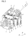
- the electrical devices 2 can be attached to a mounting rail 6 in a form-fitting manner via a fastening device 22, as is exemplified in FIG Fig. 3 is shown, and can be combined on the mounting rail 6 with other electrical devices 2, for example other terminal blocks or electronic devices that, for example, take on control or automation functions in the context of an industrial plant.
- an electrical system can be created, for example, within a control cabinet.
- the mounting rail 6 can be used to arrange electrical devices 2 in a modular manner with a large number of variants for combining completely different electrical devices 2 with one another.
- inventions according to Figure 1A and 2A differ in the dimensioning of the electrical devices 2 in the form of the terminal blocks, but are otherwise functionally the same.
- the electrical devices 2 are combined with one another in the form of terminal blocks to form an assembly 1, in that identical electrical devices 2 are arranged on an auxiliary transport device in the form of a carrier tape 3.
- the electrical devices 2 are connected to one another via the carrier tape 3, so that the electrical devices 2 can be handled and, for example, transported in a simple manner. This is detailed in the DE 10 2013 112 789 A1 described, the content of which should be included here.
- the electrical devices 2 should - if they are attached to a mounting rail 6 to provide an electrical system, as in FIG Fig. 3 shown, are combined with one another - be identified via labeled marking plates 40. This is intended to make it possible to distinguish the electrical devices 2 from one another in order, for example, to identify predetermined slots 21 for electrical conductors.
- marking plates 40 are customary to label marking plates 40 and then to apply them to the electrical devices 2 already mounted on the mounting rail 6 in order to identify the electrical devices 2 in this way.
- the marking plates 40 can be individually labeled, for example on the part of the manufacturer of the electrical devices 2, and the labeled marking plates 40 can be delivered together with the electrical devices 2 (but still separately from them).
- attaching the marking plates 40 to the electrical devices 2 then requires a large amount of manual labor in order to apply individual marking plates 40 to the electrical devices 2 that have already been installed.
- the marking plates 40 be applied to the electrical devices 2 in an unlabeled manner and only after the electrical devices 2 have been mounted on the mounting rail 6 to be labeled using a laser labeling device 5.
- the electrical devices 2 are thus already provided with (but unlabeled) marking labels 40 arranged thereon provided and arranged on the support rail 6 and are then, after assembly on the support rail 6, individually inscribed by the laser inscription device 5.
- the marking plates 40 are not located in one plane.
- the use of a laser labeling device 5 which generates a flexibly controllable and alignable laser beam L for labeling enables contactless labeling of the marking plates 40 arranged in different labeling planes in a simple and reliable manner.
- electrical devices 2 As in FIG Figure 1A and 2A shown, initially combined to form an assembly 1, this assembly 1 being connected to one another in the illustrated embodiment via a carrier tape 3 and the electrical devices 2 thus being held in position with respect to one another.
- the electrical devices 2 are lined up along a longitudinal direction X in such a way that marking fields 20 of the electrical devices 2 adjoin one another along the longitudinal direction X and form a contiguous row extending along the longitudinal direction X.
- a contiguous groove N extending along the longitudinal direction X is formed on the assembly 1.
- a contiguous marking strip 4 can be used by the marking strip 4 is glued to the row of marking fields 20.
- undercuts 200 are formed on the lateral edges of the groove N, so that when the marking strip 4 is inserted into the groove N, a form fit between the marking strip 4 and the undercuts 200 is produced.
- the marking strip 4 can have a trapezoidal shape tapering in the attachment direction in cross-section transverse to the longitudinal direction X, which facilitates the insertion of the marking strip 4 into the groove N.
- the electrical devices 2 each have two opposite marking fields 20 which, when lined up to form the assembly 1, form two opposite grooves N, into each of which a marking strip 4 can be inserted.
- FIG Figures 4A, 4B and 5A, 5B shown along the longitudinal direction X are lined up marking plates 40, which are connected to one another on a first side via a fixing strip 41 and on a second side facing away from the first side carry an adhesive layer 402, via which the individual marking plates 40 on assigned marking fields 20 of the electrical devices 2 can be glued.
- the embodiments according to Figures 4A, 4B and 5A, 5B differ in the division of the marking plates 40 along the longitudinal axis X:
- the exemplary embodiment according to FIG Figures 4A, 4B has a comparatively small division with marking plates 40 which are short in the longitudinal axis X and is therefore suitable for comparatively narrow electrical devices 2.
- the embodiment according to Figures 5A, 5B on the other hand, in the longitudinal direction X, it has a comparatively large pitch with marking plates 40 which are comparatively long in the longitudinal direction X.
- the marking plates 40 are connected to one another via the fixing strips 41, so that a coherent marking strip 4 is created.
- the marking plates 40 are basically present individually and are individually connected to the fixing strip 41.
- the fixing strip 41 is detachable so that the marking plates 40 can be separated by pulling off the fixing strip 41.
- the assembly 1 of the electrical devices 2 is present with marking plates 40 which can be written on arranged on the marking fields 20, as shown in FIG Figure 1C and 2C is shown.
- FIG. 11 shows a cross-sectional view through the marking strip 4 along the line AA in FIG Figures 4A and 5A .
- Each marking label 40 is formed by a base layer 401 which, in the exemplary embodiment shown, is provided with a cover layer 400 on the side facing the fixing strip 41 and has an adhesive layer 402 on the side facing away from the fixing strip 41.
- the fixing strip 41 is arranged on the cover layer 400, and over the fixing strip 41 are the Marking plates 40 connected to one another.
- a protective film can be applied in order to prevent the marking plates 40 from sticking inadvertently.
- the marker plates 40 are, as in FIG Fig. 3 shown schematically, laser markable.
- a laser beam L from a laser marking device 5 can be directed onto a single marking plate 40 in order to individually mark the marking plate 40 of an electrical device 2 already arranged on a mounting rail 6.
- the cover layer 400 is removed in certain areas by means of the laser beam L.
- the cover layer 400 and the base layer 401 for example, have a different color and thus, by removing the cover layer 400, inscription with the contrast of the different colors of the cover layer 400 and the base layer 401 is produced.
- laser-inscribable materials are available, which can be single-layer or multi-layered.
- a single-layer material with only one base layer 401 can also be used.
- a laser beam L causes a material change on the base layer 401, which leads to a change in color and thereby produces an inscription.
- PC Polycarbonate
- PBT polybutylene terephthalate
- ABS acrylic butadiene styrene
- PC can be directly laser marked due to its carbon content.
- a laser beam causes a carbonization of the material and thus a changed color, which can be used for labeling.
- the materials can optionally have additional additives for improved laser writability.
- the present concept is based on the fact that initially a coherent marking strip 4 with separable marking plates 40 is arranged on an assembly 1 of electrical devices 2.
- the electrical devices 2 are preferably of the same design and thus have the same dimensions, so that a contiguous row of marking fields 20 is created by lining up the electrical devices 2, on which the marking strip 4 can be arranged.
- the assembly 1 can be used, for example, in an automatic equipping machine for equipping a mounting rail 6, so that individual electrical devices 2 can be removed and attached to a mounting rail 6. After placing it on the mounting rail 6, the marking plates 40 attached to the electrical devices 2 can then be individually labeled.
- the labeling is therefore preferably carried out when the electrical devices 2 are already attached to the mounting rail 6.
- the marking strip 4 is coherent in its initial state and has marking plates 40 lined up in a row, which can be separated in order to assign individual marking plates 40 to individual electrical devices 2.
- the use of a fixing strip 41 is not mandatory here, but the marking plates 40 can also be connected to one another in another way in the initial state of the marking strip 4, but can be separated.
- FIGS 7A, 7B and 8A, 8B show Figures 7A, 7B and 8A, 8B , these two exemplary embodiments - analogously to the exemplary embodiments according to FIG Figures 4A, 4B and 5A, 5B - Only differentiate on the basis of the division of the marking plates 40 along the longitudinal direction X.
- the exemplary embodiment according to FIG Figures 7A, 7B a comparatively small division with short marking plates 40 (measured in the longitudinal direction X).
- the embodiment according to Figures 8A, 8B In contrast, it has a comparatively large pitch with marking plates 40 which are long in the longitudinal direction X.
- the marking plates 40 are connected to one another in one piece in the initial state, so that an integral, coherent marking strip 4 is created.
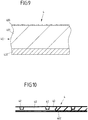
- the basic structure of the individual marking plates 40 is as shown in the sectional view according to FIG Fig. 9 can be seen, identical to the structure of the marking plates 40 in the embodiment according to FIG Figures 4A, 4B and 5A, 5B , but in the initial state there is no fixing strip 41 (as in the sectional view according to FIG Fig. 6 ) is available.
- the marking plates 40 are integrally connected to one another in the initial state, as is shown in the enlarged illustration according to FIG Fig. 10 can be seen.
- the marking plates 40 are integrally connected to one another in the initial state, but are structurally subdivided by means of separating lines 42 molded into the marking strips 4 and can thus be separated.
- the individual marking plates 40 can be separated from one another along the dividing lines 42 and thus isolated, which can be done by a (cutting) tool or by tearing the marking strip 4 along the dividing lines 42 when the electrical devices 2 of the assembly 1 are isolated.
- the marking plates 40 in the initial state can be surrounded by excess material 44 which is structurally separated from the marking plates 40 by means of separating lines 43 formed in the marking strips 4.
- An adhesive layer 402 is only provided on the marking plates 40, but not on the excess material 44, so that the excess material 44 can be easily removed before or after sticking the marking strip 4 to the assembly 1 of electrical devices 2 by tearing at the dividing lines 43 .
- very different laser-inscribable materials can be used to produce the marking plates. These materials can have a single layer or a multilayer structure.
- a fixing strip for connecting the marking plates to one another in the initial state, this fixing strip can be detached from the marking plates in a simple manner without adhesive residues remaining on the marking plates.
- a weakly adhesive adhesive can be used to connect the fixing strip to the marking plates in the initial state.
- the adhesive layer for connecting the marking plates to the electrical devices is strongly adhesive and thus creates a firm connection between the individual marking plates and the associated marking fields on the electrical devices.
- the electrical devices can be made very differently.
- the electrical devices can be implemented as terminal blocks.
Description
Die Erfindung betrifft ein Verfahren zum Anbringen von Markierungsschildern an einer Mehrzahl von an einer Tragschiene anordbaren elektrischen Geräten nach dem Oberbegriff des Anspruchs 1.The invention relates to a method for attaching marker plates to a plurality of electrical devices that can be arranged on a mounting rail.
Ein derartiges Verfahren dient zum Anbringen von Markierungsschildern an einer Mehrzahl von an einer Tragschiene anordbaren elektrischen Geräten, die jeweils ein Markierungsfeld, an dem ein beschriftbares Markierungsschild befestigbar ist, aufweisen.Such a method is used to attach marking plates to a plurality of electrical devices that can be arranged on a mounting rail and each have a marking field on which a marking plate that can be inscribed can be attached.
Bei dem Verfahren werden die elektrischen Geräte entlang einer Längsrichtung zur Bereitstellung einer Baugruppe aneinander angereiht derart, dass die Markierungsfelder der elektrischen Geräte entlang der Längsrichtung aneinander anschließen und eine durchgehende, entlang der Längsrichtung erstreckte Reihe bilden.In the method, the electrical devices are lined up along a longitudinal direction to provide an assembly in such a way that the marking fields of the electrical devices adjoin one another along the longitudinal direction and form a continuous row extending along the longitudinal direction.
Eine derartige Baugruppe ist beispielsweise aus der
An eine Tragschiene ansetzbare elektrische Geräte, beispielsweise Reihenklemmen oder Elektronikgeräte, die zur Durchführung von Steuerungs- oder Automatisierungsfunktionen beispielsweise im Rahmen einer Industrieanlage dienen, können beispielsweise in einem Schaltschrank miteinander kombiniert und hierzu an eine in dem Schaltschrank montierte Tragschiene angesetzt werden, um eine elektrische Anlage innerhalb des Schaltschranks bereitzustellen.Electrical devices that can be attached to a mounting rail, for example terminal blocks or electronic devices that are used to carry out control or automation functions, for example in the context of an industrial plant, can for example be combined with one another in a control cabinet and for this purpose mounted on one in the control cabinet Mounting rail can be attached to provide an electrical system within the control cabinet.
Um die einzelnen elektrischen Geräte zu kennzeichnen und einem Nutzer in übersichtlicher Weise beispielsweise das Anschließen von elektrischen Leitungen zu ermöglichen, ist herkömmlich vorgesehen, an den elektrischen Geräten Markierungsschilder anzubringen. Während zur Bestückung von Tragschienen beispielsweise mit Reihenklemmen heutzutage Automaten eingesetzt werden, wie sie beispielsweise aus der
Aus der
Aus der
Eine andere Vorrichtung zur Kennzeichnung von Schaltanlagen-Reihenklemmen ist aus der
Die
Aufgabe der vorliegenden Erfindung ist es, ein Verfahren zum Anbringen von Markierungsschildern an elektrischen Geräten sowie einen Markierungsstreifen und eine Baugruppe von elektrischen Geräten bereitzustellen, die in einfacher, automatisierbarer Weise ein Beschriften von elektrischen Geräten, beispielsweise Reihenklemmen ermöglichen.The object of the present invention is to provide a method for attaching marking plates to electrical devices, as well as a marking strip and an assembly of electrical devices that allow electrical devices, for example terminal blocks, to be labeled in a simple, automatable manner.
Diese Aufgabe wird durch einen Gegenstand mit den Merkmalen des Anspruchs 1 gelöst.This object is achieved by an object with the features of
Das vorgestellte Verfahren stellt eine Abkehr von herkömmlich bekannten Verfahren zum Beschriften von elektrischen Geräten, die an einer Tragschiene angeordnet werden sollen, dar. So werden im Rahmen des Verfahren elektrische Geräte, an denen beschriftbare Markierungsschilder anzubringen sind, zunächst zu einer Baugruppe gruppiert und dazu derart aneinander angereiht, dass Markierungsfelder der elektrischen Geräte entlang einer Längsrichtung aneinander anschließen und eine durchgehende, entlang der Längsrichtung erstreckte Reihe bilden. An dieser Reihe kann sodann ein (zusammenhängender) Markierungsstreifen befestigt werden, der eine Mehrzahl von beschriftbaren Markierungsschildern aufweist. Die Markierungsschilder werden so an der Reihe von elektrischen Geräten angebracht, dass jedem Markierungsfeld eines elektrischen Gerätes ein (oder mehrere) Markierungsschilder zugeordnet sind. Nach Anbringen des Markierungsstreifens werden die Markierungsschilder vereinzelt, sodass an dem Markierungsfeld eines jeden elektrischen Gerätes ein oder mehrere Markierungsschilder verbleiben.The presented method represents a departure from conventionally known methods for labeling electrical devices that are to be arranged on a mounting rail. Thus, within the scope of the method, electrical devices to which markable labels are to be attached are first grouped into an assembly and for this purpose lined up so that marking fields of the electrical devices adjoin one another along a longitudinal direction and form a continuous row extending along the longitudinal direction. A (coherent) marking strip can then be attached to this row, which has a plurality of marking plates that can be written on. The marking plates are attached to the row of electrical devices in such a way that one (or more) marking plates are assigned to each marking field of an electrical device. After the marking strip has been applied, the marking plates are separated so that one or more marking plates remain on the marking field of each electrical device.
Die an den Markierungsfeldern der elektrischen Geräte angeordneten Markierungsschilder können mittels einer Laserbeschriftungseinrichtung beschriftet werden. Dies kann vor oder nach dem Ansetzen der elektrischen Geräte an eine Tragschiene erfolgen.The marking plates arranged on the marking fields of the electrical devices can be inscribed by means of a laser inscription device. This can be done before or after the electrical devices are attached to a mounting rail.
Mittels des Verfahrens werden somit zunächst in einfach zu automatisierender Weise Markierungsschilder an einer Mehrzahl von elektrischen Geräten angebracht, und erst anschließend werden die Markierungsschilder durch eine Laserbeschriftungseinrichtung beschriftet. Die Beschriftung kann beispielsweise erfolgen, wenn die elektrischen Geräte bereits an eine Tragschiene angesetzt und mit anderen elektrischen Geräten kombiniert sind, wozu ein Laserstrahl der Laserbeschriftungseinrichtung so gesteuert wird, dass in gezielter Weise auf den einzelnen Markierungsschildern der elektrischen Geräte eine geeignete, individuelle Beschriftung angebracht wird.By means of the method, marking plates are initially attached to a plurality of electrical devices in a manner that is easy to automate, and only then are the marking plates inscribed by a laser inscription device. The labeling can take place, for example, when the electrical devices are already attached to a mounting rail and combined with other electrical devices, for which purpose a laser beam from the laser labeling device is controlled in such a way that a suitable, individual label is applied to the individual marking plates of the electrical devices in a targeted manner .
Die elektrischen Geräte werden somit zunächst mit unbeschrifteten Markierungsschildern versehen und können so ausgeliefert und an eine Tragschiene angesetzt werden. Erst nach Ansetzen an die Tragschiene erfolgt dann die Beschriftung, was die Fehleranfälligkeit bei der Beschriftung reduzieren kann.The electrical devices are thus initially provided with unlabeled marking labels and can thus be delivered and attached to a mounting rail. First after placing it on the mounting rail, the labeling takes place, which can reduce the susceptibility to errors when labeling.
Der Markierungsstreifen kann bevorzugt entlang der Reihe der Markierungsfelder auf die elektrischen Geräte aufgeklebt werden. Hierzu kann der Markierungsstreifen an den Markierungsschildern eine Klebeschicht aufweisen, die eine Klebeverbindung mit den elektrischen Geräten eingeht und über die die Markierungsschilder einzeln an den jeweils zugeordneten Markierungsfeldern der elektrischen Geräte befestigt werden.The marking strip can preferably be glued onto the electrical devices along the row of marking fields. For this purpose, the marking strip on the marking plates can have an adhesive layer which forms an adhesive connection with the electrical devices and via which the marking plates are individually attached to the respectively assigned marking fields of the electrical devices.
In einer konkreten Ausgestaltung können die Markierungsfelder der elektrischen Geräte an Vertiefungen der elektrischen Geräte vorgesehen sein. Die Vertiefungen der elektrischen Geräte bilden, wenn die elektrischen Geräte aneinander angereiht sind, eine längs entlang der Längsrichtung erstreckte Nut aus, in die der Markierungsstreifen eingesetzt werden kann, um den Markierungsstreifen an den elektrischen Geräten zu befestigen. Die Markierungsfelder, an denen die Markierungsschilder des Markierungsstreifens anzubringen sind, können hierbei beispielsweise an Böden der Vertiefungen der elektrischen Geräte gebildet sein, wobei denkbar und möglich ist, dass die Vertiefungen an seitlichen Kanten jeweils Hinterschnitte aufweisen, die bei Einsetzen des Markierungsstreifens in die Nut eine formschlüssige Verbindung herstellen und somit den Markierungsstreifen formschlüssig in der Nut halten. Der Markierungsstreifen kann hierzu im Querschnitt eine sich in Ansetzrichtung konisch verjüngende, trapezähnliche Form aufweisen, die ein Einsetzen des Markierungsstreifens in die Nut erleichtert.In a specific embodiment, the marking fields of the electrical devices can be provided on recesses in the electrical devices. When the electrical devices are lined up next to one another, the recesses of the electrical devices form a groove which extends longitudinally along the longitudinal direction and into which the marking strip can be inserted in order to fasten the marking strip to the electrical devices. The marking fields to which the marking strips of the marking strips are to be attached can be formed, for example, on the bottoms of the recesses of the electrical devices, it being conceivable and possible for the recesses to each have undercuts on the side edges that create a Establish a positive connection and thus hold the marking strip in the groove with a positive fit. For this purpose, the marking strip can have a trapezoidal shape which tapers conically in the attachment direction and which facilitates the insertion of the marking strip into the groove.
Um eine kompakte, einfach zu handhabende Baugruppe bereitzustellen, können die elektrischen Geräte, beispielsweise in Form von Reihenklemmen, z.B. auf einem entlang der Längsrichtung erstreckten Trägerband aneinander angereiht werden. Das Trägerband stellt eine Transporthilfsvorrichtung zur Verfügung, wie sie in der
Der Markierungsstreifen liegt in einem Ausgangszustand als durchgehender Streifen vor, bei dem die Markierungsschilder in unterschiedlicher Weise miteinander verbunden sein können.In an initial state, the marking strip is in the form of a continuous strip in which the marking plates can be connected to one another in different ways.
So können in einer ersten Variante die Markierungsschilder in dem Ausgangszustand über einen Fixierstreifen miteinander verbunden sein, wobei der Fixierstreifen von den Markierungsschildern lösbar ist, um die Markierungsschilder zu vereinzeln. Der Markierungsstreifen kann somit - bei über den Fixiertreifen miteinander verbundenen Markierungsschildern - an die Reihe von Markierungsfeldern der elektrischen Geräte angesetzt werden, um die Markierungsschilder beispielsweise mit den elektrischen Geräten zu verkleben. Ist der Markierungsstreifen an den elektrischen Geräten angeordnet, kann der Fixierstreifen abgezogen werden, wobei die Markierungsschilder an den elektrischen Geräten verbleiben und die elektrischen Geräte somit mit beschriftbaren Markierungsschildern bestückt sind.In a first variant, the marking plates can be connected to one another via a fixing strip in the initial state, the fixing strip being detachable from the marking plates in order to separate the marking plates. The marking strip can thus - in the case of marking plates connected to one another via the fixing strip - be attached to the row of marking fields of the electrical devices in order to glue the marking plates to the electrical devices, for example. If the marking strip is arranged on the electrical devices, the fixing strip can be peeled off, the marking plates remaining on the electrical devices and the electrical devices thus being equipped with marking plates that can be written on.
In einer anderen, zweiten Variante können die Markierungsschilder in dem Ausgangszustand auch einstückig miteinander verbunden sein. Die Markierungsschilder können hierbei voneinander vereinzelt werden, beispielsweise indem die Markierungsschilder entlang von an den Markierungsstreifen geformten Trennlinien voneinander getrennt werden. Die Trennlinien können beispielsweise durch gezielte Materialschwächung, beispielsweise durch Perforation oder durch Materialverdünnung, an dem Markierungsstreifen geformt sein. Entlang der Trennlinien können benachbarte Markierungsschilder voneinander gelöst werden, was durch ein geeignetes Werkzeug oder auch bei Trennen der elektrischen Geräte voneinander selbsttätig erfolgen kann.In another, second variant, the marking plates can also be connected to one another in one piece in the initial state. The marking plates can be separated from one another, for example by separating the marking plates from one another along separating lines formed on the marking strips. The dividing lines can be formed on the marking strip, for example, by targeted material weakening, for example by perforation or by material thinning. Adjacent marking plates can be detached from one another along the dividing lines, which can be done automatically using a suitable tool or even when the electrical devices are separated from one another.
Sind mittels des beschriebenen Verfahrens die elektrischen Geräte der Baugruppe mit Markierungsschildern bestückt worden, so können einzelne oder sämtliche der elektrischen Geräte an eine Tragschiene angesetzt werden, um die Tragschiene zu bestücken und auf diese Weise eine elektrischen Anlage beispielsweise innerhalb eines Schaltschranks bereitzustellen. Hierzu kann ein elektrisches Gerät aus der Baugruppe der aneinander gereihten elektrischen Geräte entnommen und an die Tragschiene angesetzt werden. Sodann kann das Markierungsschild des entnommenen und an die Tragschiene angesetzten elektrischen Gerätes mit einer Laserbeschriftungseinrichtung beschriftet werden, um auf diese Weise das elektrische Gerät z.B. in seiner Funktion und/oder in seinen Anschlüssen zu kennzeichnen.If the electrical devices of the assembly have been equipped with marking plates by means of the described method, then some or all of the electrical devices can be attached to a mounting rail in order to equip the mounting rail and in this way provide an electrical system, for example within a control cabinet. For this purpose, an electrical device can be removed from the assembly of the electrical devices in a row and attached to the mounting rail. The marking plate of the electrical device that has been removed and attached to the mounting rail can then be labeled with a laser labeling device in order to identify the electrical device, for example, in its function and / or in its connections.
An der Tragschiene können ganz unterschiedliche elektrische Geräte ganz unterschiedlicher Bauform miteinander kombiniert werden. Über die Laserbeschriftungseinrichtung können Markierungsschilder der unterschiedlichen elektrischen Geräte beschriftet werden, was bei bereits an die Tragschiene angeordneten elektrischen Geräten erfolgen kann.Very different electrical devices of very different designs can be combined with one another on the mounting rail. Marking plates of the different electrical devices can be labeled via the laser labeling device, which can be done with electrical devices already arranged on the mounting rail.
Ein Markierungsstreifen zum Befestigen an einer Reihe von Markierungsfeldern einer Mehrzahl von aneinander angereihten, an einer Tragschiene anordbaren elektrischen Geräten weist eine Mehrzahl von in einem Ausgangszustand miteinander verbundenen, zu vereinzelnden, mit einer Laserbeschriftungseinrichtung beschriftbaren Markierungsschildern auf. Dadurch, dass der Markierungsstreifen im Ganzen an die Reihe von Markierungsfeldern der aneinander angereihten elektrischen Geräte angebracht werden kann, können die elektrischen Geräte in einem Arbeitsschritt mit Markierungsschildern versehen werden, die nachträglich durch Laserbeschriftung beschriftet werden können. Jedes Markierungsschild des Markierungsstreifens kann beispielsweise eine Klebeschicht zum Befestigen an einem Markierungsfeld eines elektrischen Gerätes aufweisen. Über die Klebeschicht kann ein jedes Markierungsschild an ein zugeordnetes Markierungsfeld eines elektrischen Gerätes angesetzt und somit mit dem Markierungsfeld verklebt werden.A marking strip for fastening to a row of marking fields of a plurality of lined up electrical devices that can be arranged on a mounting rail has a plurality of marking plates that are connected to one another in an initial state, are to be separated and can be labeled with a laser marking device. Because the marking strip as a whole can be attached to the row of marking fields of the side-by-side electrical devices, the electrical devices can be provided with marking plates in one work step, which can then be labeled using laser inscription. Each marking label of the marking strip can, for example, have an adhesive layer for attachment to a marking field of an electrical device. Each marking plate can be attached to an assigned marking field of an electrical device via the adhesive layer and thus glued to the marking field.
Die Markierungsschilder des Markierungsstreifens sind durch eine Laserbeschriftungseinrichtung beschriftbar. Mittels der Laserbeschriftungseinrichtung kann ein Laserstrahl auf ein Markierungsschild gerichtet werden, um auf diese Weise eine vorbestimmte, individuelle Kennzeichnung auf dem Markierungsschild anzubringen.The marking plates of the marking strip can be written on using a laser marking device. By means of the laser marking device, a laser beam can be directed onto a marking plate in order to apply a predetermined, individual identification to the marking plate in this way.
Die Markierungsschilder können einen einlagigen Grundaufbau eines laserbeschriftbaren Materials aufweisen. Bei der Laserbeschriftung wird in diesem Fall das Material selbst verändert, sodass in dem Material eine Farbänderung ausgelöst wird. Alternativ kann ein mehrlagiger Grundaufbau verwendet werden, bei dem auf einem Grundwerkstoff eine Deckschicht angeordnet ist, die mittels eines Laserstrahls abgetragen werden kann, um auf diese Weise eine Beschriftung herzustellen.The marking plates can have a single-layer basic structure of a laser-inscribable material. In this case, laser marking changes the material itself so that a color change is triggered in the material. Alternatively, a multi-layer basic structure can be used in which a cover layer is arranged on a base material, which cover layer can be removed by means of a laser beam in order to produce an inscription in this way.
In einem Ausgangszustand liegt der Markierungsstreifen als zusammenhängender Streifen vor. In dem Ausgangszustand sind, in einer ersten Variante, die Markierungsschilder des Markierungsstreifens über einen Fixierstreifen miteinander verbunden, wobei der Fixierstreifen zur Vereinzelung der Markierungsschilder von den Markierungsschildern abgelöst werden kann.In an initial state, the marking strip is present as a continuous strip. In the initial state, in a first variant, the marking plates of the marking strip are connected to one another via a fixing strip, the Fixing strips for separating the marking plates can be detached from the marking plates.
Der Fixierstreifen ist in dem Ausgangszustand vorzugsweise an einer ersten Seite der Markierungsschilder angeordnet, die einer zweiten Seite, über die die Markierungsschilder an den elektrischen Geräten befestigt werden können, abgewandt ist. Nach Aufbringen des Markierungsstreifens auf die elektrischen Geräte kann der Fixierstreifen von den Markierungsschildern abgezogen werden, sodass die Markierungsschilder voneinander vereinzelt werden und die einzelnen elektrischen Geräte mit getrennten Markierungsschildern versehen sind.In the initial state, the fixing strip is preferably arranged on a first side of the marking plates which faces away from a second side via which the marking plates can be attached to the electrical devices. After the marking strip has been applied to the electrical devices, the fixing strip can be peeled off the marking plates, so that the marking plates are separated from one another and the individual electrical devices are provided with separate marking plates.
In einer zweiten Variante sind die Markierungsschilder in einem Ausgangszustand einstückig miteinander verbunden und können entlang von Trennlinien voneinander vereinzelt werden. Die Trennlinien können beispielsweise durch gezielte Materialschwächung, beispielsweise durch Perforation oder Materialverdünnung, in den Markierungsstreifen eingebracht sein, sodass die Markierungsschilder entlang der Trennlinien voneinander abgerissen werden können. Bei dieser zweiten Variante kann somit ein (zusätzlicher) Fixierstreifen zum Verbinden der Markierungsschilder entfallen. In dem Ausgangszustand sind die Markierungsschilder einstückig miteinander verbunden. Das Trennen der Markierungsschilder kann beispielsweise bei Entfernen der elektrischen Geräte voneinander selbsttätig erfolgen, ohne dass hierzu ein zusätzlicher Arbeitsschritt erforderlich ist.In a second variant, the marking plates are connected to one another in one piece in an initial state and can be separated from one another along dividing lines. The dividing lines can be introduced into the marking strips, for example, by targeted material weakening, for example by perforation or material thinning, so that the marking plates can be torn from one another along the dividing lines. In this second variant, an (additional) fixing strip for connecting the marking plates can thus be omitted. In the initial state, the marking plates are connected to one another in one piece. The marking labels can be separated automatically, for example, when the electrical devices are removed from one another, without an additional work step being required for this purpose.
Eine Baugruppe weist eine Mehrzahl von an einer Tragschiene anordbaren elektrischen Geräten auf, die jeweils ein Markierungsfeld, an dem ein Markierungsschild befestigbar ist, umfassen. Die elektrischen Geräte sind entlang einer Längsrichtung derart aneinander angereiht, dass die Markierungsfelder der elektrischen Geräte entlang der Längsrichtung aneinander anschließen und eine durchgehende, entlang der Längsrichtung erstreckte Reihe bilden. Hierbei ist vorgesehen, dass ein Markierungsstreifen, der eine Mehrzahl von den Markierungsfeldern der elektrischen Geräte zugeordneten, mit einer Laserbeschriftungseinrichtung beschriftbaren, vereinzelbaren Markierungsschildern aufweist, entlang der Reihe an den elektrischen Geräten befestigt ist.An assembly has a plurality of electrical devices that can be arranged on a mounting rail, each of which includes a marking field to which a marking plate can be attached. The electrical devices are lined up along a longitudinal direction in such a way that the marking fields of the electrical devices adjoin one another along the longitudinal direction and form a continuous row extending along the longitudinal direction. It is provided here that a marking strip, which has a plurality of marking plates that are assigned to the marking fields of the electrical devices and that can be labeled with a laser marking device, is attached to the electrical devices along the row.
Die Baugruppe ergibt sich vorzugsweise als Zwischenerzeugnis bei dem vorangehend beschriebenen Verfahren. So liegen nach dem Anbringen des Markierungsstreifens die elektrischen Geräte mit daran angeordneten Markierungsschildern vor, wobei die Markierungsschilder durch Abziehen eines Fixierstreifens oder durch Trennen der Markierungsfelder entlang von Trennlinien voneinander bereits vereinzelt sein können oder nicht. Die Baugruppe von elektrischen Geräten kann beispielsweise auf einem Trägerband angeordnet sein und auf diese Weise einen kompakten Verbund darstellen, der in einfacher Weise gehandhabt werden kann.The assembly is preferably obtained as an intermediate product in the method described above. Thus, after the marking strip has been applied, the electrical devices with marking plates arranged thereon are present, with the Marking plates may or may not already be isolated from one another by pulling off a fixing strip or by separating the marking fields along separating lines. The assembly of electrical devices can, for example, be arranged on a carrier tape and in this way represent a compact assembly that can be handled in a simple manner.
Die Baugruppe kann beispielsweise durch einen Hersteller der elektrischen Geräte an einen Endabnehmer ausgeliefert werden, wobei die Beschriftung der Markierungsschilder der elektrischen Geräte beim Endabnehmer nach Ansetzen der elektrischen Geräte an eine Tragschiene erfolgen kann.The assembly can, for example, be delivered to an end user by a manufacturer of the electrical devices, with the labeling of the marking plates of the electrical devices at the end user being possible after the electrical devices have been attached to a mounting rail.
Der der Erfindung zugrundeliegende Gedanke soll nachfolgend anhand der in den Figuren dargestellten Ausführungsbeispiele näher erläutert werden. Es zeigen:
- Fig. 1A
- eine perspektivische Ansicht einer Baugruppe von elektrischen Geräten in Form von Reihenklemmen;
- Fig. 1 B
- eine Ansicht der Baugruppe, mit an den elektrischen Geräten angebrachten Markierungsstreifen;
- Fig. 1C
- eine Ansicht der Baugruppe nach Vereinzelung von Markierungsschildern der Markierungsstreifen;
- Fig. 2A
- eine Ansicht einer Baugruppe von elektrischen Geräten nach einem zweiten Ausführungsbeispiel;
- Fig. 2B
- eine Ansicht einer Baugruppe nach Ansetzen von Markierungsstreifen;
- Fig. 2C
- eine Ansicht der Baugruppe nach Vereinzelung der Markierungsschilder;
- Fig. 3
- eine Ansicht von unterschiedlichen, an eine Tragschiene angesetzten elektrischen Geräten;
- Fig. 4A
- eine Seitenansicht eines ersten Ausführungsbeispiels eines Markierungsstreifens;
- Fig. 4B
- eine Draufsicht auf den Markierungsstreifen;
- Fig. 5A
- eine Seitenansicht eines anderen Ausführungsbeispiels eines Markierungsstreifens mit größerer Teilung;
- Fig. 5B
- eine Draufsicht auf den Markierungsstreifen gemäß
Fig. 5A ; - Fig. 6
- eine Schnittansicht entlang der Linien A-A gemäß
Fig. 4A und 5A ; - Fig. 7A
- eine entlang der Linie B-B gemäß
Fig. 7B teilweise geschnittene Seitenansicht eines weiteren Ausführungsbeispiels eines Markierungsstreifens; - Fig. 7B
- eine Draufsicht auf den Markierungsstreifen;
- Fig. 8A
- eine entlang der Linie B-B gemäß
Fig. 8B teilweise geschnittene Seitenansicht eines wiederum weiteren Ausführungsbeispiels eines Markierungsstreifens, mit im Vergleich zum Markierungsstreifen gemäßFig. 7A und 7B größerer Teilung; - Fig. 8B
- eine Draufsicht auf den Markierungsstreifen;
- Fig. 9
- eine Querschnittsansicht entlang der Linie A-A gemäß
Fig. 7A und 8A ; und - Fig. 10
- eine vergrößerte Ansicht im Ausschnitt C gemäß
Fig. 7A .
- Figure 1A
- a perspective view of an assembly of electrical devices in the form of terminal blocks;
- Fig. 1B
- a view of the assembly, with marking strips attached to the electrical devices;
- Figure 1C
- a view of the assembly after separation of marking plates of the marking strips;
- Figure 2A
- a view of an assembly of electrical devices according to a second embodiment;
- Figure 2B
- a view of an assembly after attaching marking strips;
- Figure 2C
- a view of the assembly after separation of the marker plates;
- Fig. 3
- a view of different, attached to a mounting rail electrical devices;
- Figure 4A
- a side view of a first embodiment of a marker strip;
- Figure 4B
- a plan view of the marker strip;
- Figure 5A
- a side view of another embodiment of a marker strip with larger pitch;
- Figure 5B
- a plan view of the marking strip according to
Figure 5A ; - Fig. 6
- a sectional view along the lines AA according to FIG
Figures 4A and 5A ; - Figure 7A
- one along the line BB according to
Figure 7B partially sectioned side view of a further embodiment of a marking strip; - Figure 7B
- a plan view of the marker strip;
- Figure 8A
- one along the line BB according to
Figure 8B partially sectioned side view of yet another embodiment of a marking strip, with in comparison to the marking strip according to FIGFigures 7A and 7B larger division; - Figure 8B
- a plan view of the marker strip;
- Fig. 9
- a cross-sectional view along the line AA according to
Figures 7A and 8A ; and - Fig. 10
- an enlarged view in section C according to
Figure 7A .
Durch Anordnen von elektrischen Geräten 2 an einer Tragschiene 6 kann eine elektrische Anlage beispielsweise innerhalb eines Schaltschranks geschaffen werden. An der Tragschiene 6 können hierbei elektrische Geräte 2 in modularer Weise mit großer Variantenvielfalt zur Kombination ganz unterschiedlicher elektrischer Geräte 2 miteinander angeordnet werden.By arranging
Die Ausführungsbeispiele gemäß
In
Die elektrischen Geräte 2 sollen -wenn sie an einer Tragschiene 6 zur Bereitstellung einer elektrischen Anlage, wie in
Herkömmlich ist beispielweise üblich, Markierungsschilder 40 zu beschriften und sodann auf die bereits an der Tragschiene 6 montierten elektrischen Geräte 2 aufzubringen, um auf diese Weise die elektrischen Geräte 2 zu kennzeichnen. Die Markierungsschilder 40 können hierbei individuell beispielsweise aufseiten des Herstellers der elektrischen Geräte 2 beschriftet werden, und die beschrifteten Markierungsschilder 40 können zusammen mit den elektrischen Geräten 2 (aber noch getrennt von diesen) ausgeliefert werden. Das Anbringen der Markierungsschilder 40 an den elektrischen Geräten 2 erfordert dann jedoch ein großes Maß an Handarbeit, um einzelne Markierungsschilder 40 auf die bereits montierten elektrischen Geräte 2 aufzubringen.Conventionally, for example, it is customary to label marking
In Abkehr von diesem bisher üblichen Konzept wird vorliegend vorgeschlagen, die Markierungsschilder 40 zunächst unbeschriftet auf die elektrischen Geräte 2 aufzubringen und erst nach Montage der elektrischen Geräte 2 an der Tragschiene 6 durch eine Laserbeschriftungseinrichtung 5 zu beschriften. Die elektrischen Geräte 2 werden somit bereits mit daran angeordneten (aber unbeschrifteten) Markierungsschildern 40 bereitgestellt und an der Tragschiene 6 angeordnet und werden sodann, nach Montage an der Tragschiene 6, durch die Laserbeschriftungseinrichtung 5 individuell beschriftet.As a departure from this hitherto common concept, it is proposed in the present case that the marking
Aufgrund der Ungleichheit der an der Tragschiene 6 montierten elektrischen Geräte 2 befinden sich die Markierungsschilder 40 nicht in einer Ebene. Durch die Verwendung einer Laserbeschriftungseinrichtung 5, die einen flexibel ansteuerbaren und ausrichtbaren Laserstrahl L zur Beschriftung erzeugt, wird in einfacher und zuverlässiger Weise eine berührungslose Beschriftung der in unterschiedlichen Beschriftungsebenen angeordneten Markierungsschilder 40 ermöglicht.Due to the inequality of the
Zur Anbringung der Markierungsschilder 40 werden elektrische Geräte 2, wie in
Dadurch, dass die Markierungsfelder 20 am Boden von Vertiefungen der elektrischen Geräte 2 angeordnet sind, wird an der Baugruppe 1 eine zusammenhängende, entlang der Längsrichtung X erstreckte Nut N gebildet. In diese Nut N kann, wie in
Zusätzlich sind an seitlichen Kanten der Nut N Hinterschnitte 200 ausgebildet, sodass bei Einsetzen des Markierungsstreifens 4 in die Nut N ein Formschluss zwischen dem Markierungsstreifen 4 und den Hinterschnitten 200 hergestellt wird. Hierzu kann der Markierungsstreifen 4 im Querschnitt quer zur Längsrichtung X eine in Ansetzrichtung sich verjüngende Trapezform aufweisen, die das Einsetzen des Markierungsstreifens 4 in die Nut N erleichtert.In addition, undercuts 200 are formed on the lateral edges of the groove N, so that when the marking
Die elektrischen Geräte 2 weisen bei den dargestellten Ausführungsbeispielen jeweils zwei gegenüberliegende Markierungsfelder 20 auf, die bei Aneinanderreihung zur Formung der Baugruppe 1 zwei gegenüberliegende Nuten N bilden, in die jeweils ein Markierungsstreifen 4 eingesetzt werden kann.In the exemplary embodiments shown, the
Der Markierungsstreifen 4 weist, wie in zwei Ausführungsbeispielen in
In einem Ausgangszustand sind die Markierungsschilder 40 über den Fixierstreifen 41 miteinander verbunden, sodass ein zusammenhängender Markierungsstreifen 4 geschaffen wird. Die Markierungsschilder 40 liegen hierbei jedoch grundsätzlich einzeln vor und sind einzeln mit dem Fixierstreifen 41 verbunden. Der Fixierstreifen 41 ist lösbar, sodass die Markierungsschilder 40 durch Abziehen des Fixierstreifens 41 vereinzelt werden können.In an initial state, the marking
So kann, wie in
Nach Abziehen des Fixierstreifens 41 liegt die Baugruppe 1 der elektrischen Geräte 2 mit an den Markierungsfeldern 20 angeordneten, beschriftbaren Markierungsschildern 40 vor, wie dies in
Die Markierungsschilder 40 sind, wie in
In diesem Zusammenhang sei angemerkt, dass ganz unterschiedliche laserbeschriftbare Materialien zur Verfügung stehen, die einlagig oder mehrlagig ausgebildet sein können. Anstelle des zweilagigen Ausführungsbeispiels (mit einer Deckschicht 400 und einer Grundschicht 401) kann beispielsweise auch ein einlagiges Material mit lediglich einer Grundschicht 401 verwendet werden. In diesem Fall wird durch einen Laserstrahl L eine Materialveränderung an der Grundschicht 401 bewirkt, die zu einer Farbänderung führt und dadurch eine Beschriftung erzeugt.In this context, it should be noted that very different laser-inscribable materials are available, which can be single-layer or multi-layered. Instead of the two-layer exemplary embodiment (with a
Als laserbeschriftbare Materialien können beispielsweise Polycarbonat (PC), Polybutylenterephthalat (PBT) oder Acrylbutadienstyrol (ABS) verwendet werden. PC beispielsweise ist aufgrund seines Kohlenstoffanteils direkt laserbeschriftbar. Ein Laserstrahl bewirkt eine Carbonisierung des Materials und dadurch eine veränderte Färbung, die zur Beschriftung verwendet werden kann. Die Materialien können gegebenenfalls zusätzliche Additive zur verbesserten Laserbeschriftbarkeit aufweisen.Polycarbonate (PC), polybutylene terephthalate (PBT) or acrylic butadiene styrene (ABS), for example, can be used as laser-inscribable materials. PC, for example, can be directly laser marked due to its carbon content. A laser beam causes a carbonization of the material and thus a changed color, which can be used for labeling. The materials can optionally have additional additives for improved laser writability.
Das vorliegende Konzept beruht darauf, dass zunächst ein zusammenhängender Markierungsstreifen 4 mit vereinzelbaren Markierungsschildern 40 auf einer Baugruppe 1 von elektrischen Geräten 2 angeordnet wird. Die elektrischen Geräte 2 sind vorzugsweise gleicher Bauart und weisen somit gleiche Abmessungen auf, sodass durch Aneinanderreihung der elektrischen Geräte 2 eine zusammenhängende Reihe von Markierungsfeldern 20 geschaffen wird, an der der Markierungsstreifen 4 angeordnet werden kann. Nach Vereinzelung der Markierungsschilder 40 durch Abziehen des Fixierstreifens 41 kann die Baugruppe 1 beispielsweise in einen Bestückungsautomaten zum Bestücken einer Tragschiene 6 eingesetzt werden, sodass einzelne elektrische Geräte 2 entnommen und an eine Tragschiene 6 angesetzt werden können. Nach Ansetzen an die Tragschiene 6 kann sodann eine individuelle Beschriftung der an den elektrischen Geräten 2 angebrachten Markierungsschilder 40 erfolgen.The present concept is based on the fact that initially a
Die Beschriftung erfolgt somit vorzugsweise, wenn die elektrischen Geräte 2 bereits an die Tragschiene 6 angesetzt sind.The labeling is therefore preferably carried out when the
Der Markierungsstreifen 4 ist in seinem Ausgangszustand zusammenhängend und weist aneinandergereihte Markierungsschilder 40 auf, die vereinzelbar sind, um einzelnen elektrischen Geräten 2 einzelne Markierungsschilder 40 zuzuordnen. Hierbei ist die Verwendung eines Fixierstreifens 41 nicht zwingend, sondern die Markierungsschilder 40 können in dem Ausgangszustand des Markierungsstreifens 4 auch in anderer Weise miteinander verbunden, aber vereinzelbar sein.The marking
Andere Ausführungsbeispiele eines Markierungsstreifens 4 zeigen
Bei den Ausführungsbeispielen gemäß
Der grundsätzliche Aufbau der einzelnen Markierungsschilder 40 ist, wie aus der Schnittansicht gemäß
Die Markierungsschilder 40 sind in dem Ausgangszustand integral miteinander verbunden, dabei aber über in den Markierungsstreifen 4 eingeformte Trennlinien 42 strukturell unterteilt und somit vereinzelbar. Entlang der Trennlinien 42 können die einzelnen Markierungsschilder 40 voneinander getrennt und somit vereinzelt werden, was durch ein (Schneide-) Werkzeug oder durch Aufreißen des Markierungsstreifens 4 entlang der Trennlinien 42 bei einem Vereinzeln der elektrischen Geräte 2 der Baugruppe 1 erfolgen kann.The marking
Wie aus den Draufsichten gemäß
Der der Erfindung zugrunde liegende Gedanke ist nicht auf die vorangehend geschilderten Ausführungsbeispiele beschränkt, sondern lässt sich grundsätzlich auch in gänzlich anders gearteter Weise verwirklichen.The idea on which the invention is based is not restricted to the exemplary embodiments described above, but can in principle also be implemented in a completely different manner.
Insbesondere sind ganz unterschiedliche laserbeschriftbare Materialien zur Verwirklichung der Markierungsschilder verwendbar. Diese Materialien können einlagig oder mehrlagig aufgebaut sein.In particular, very different laser-inscribable materials can be used to produce the marking plates. These materials can have a single layer or a multilayer structure.
Ist ein Fixierstreifen zum Verbinden der Markierungsschilder in dem Ausgangszustand miteinander vorgesehen, so ist dieser Fixierstreifen in einfacher Weise von den Markierungsschildern lösbar, ohne dass Kleberückstände an den Markierungsschildern verbleiben. Hierzu kann ein schwach klebender Klebstoff zur Verbindung des Fixierstreifens mit den Markierungsschildern in dem Ausgangszustand verwendet werden.If a fixing strip is provided for connecting the marking plates to one another in the initial state, this fixing strip can be detached from the marking plates in a simple manner without adhesive residues remaining on the marking plates. For this purpose, a weakly adhesive adhesive can be used to connect the fixing strip to the marking plates in the initial state.
Die Klebeschicht zur Verbindung der Markierungsschilder mit den elektrischen Geräten ist demgegenüber stark klebend und schafft somit eine feste Verbindung zwischen den einzelnen Markierungsschildern und den zugeordneten Markierungsfeldern an den elektrischen Geräten.In contrast, the adhesive layer for connecting the marking plates to the electrical devices is strongly adhesive and thus creates a firm connection between the individual marking plates and the associated marking fields on the electrical devices.
Die elektrischen Geräte können ganz unterschiedlich beschaffen sein. So können die elektrischen Geräte als Reihenklemmen verwirklicht sein. Denkbar und möglich ist aber auch, dass die elektrischen Geräte Elektronikgeräte verwirklichen, die beispielsweise eine Leiterplatte mit daran angeordneten elektronischen Komponenten aufweisen.The electrical devices can be made very differently. The electrical devices can be implemented as terminal blocks. However, it is also conceivable and possible for the electrical devices to implement electronic devices which, for example, have a printed circuit board with electronic components arranged thereon.
- 11
- Baugruppemodule
- 22
- Elektrisches Gerät (Reihenklemme)Electrical device (terminal block)
- 2020th
- MarkierungsfeldCheckbox
- 200200
- HinterschnittUndercut
- 2121
- KontaktstelleContact point
- 2222nd
- BefestigungseinrichtungFastening device
- 33
- TrägerbandCarrier tape
- 44th
- MarkierungsstreifenMarking strips
- 4040
- MarkierungsschildMarker sign
- 400400
- DeckschichtTop layer
- 401401
- Grundschichtbase layer
- 402402
- KlebeschichtAdhesive layer
- 4141
- FixierstreifenFixing strips
- 42, 4342, 43
- Trennlinieparting line
- 4444
- ÜberschussmaterialExcess material
- 55
- LaserbeschriftungseinrichtungLaser marking device
- 66th
- TragschieneMounting rail
- LL.
- Laserstrahllaser beam
- NN
- NutGroove
- X, Y, ZX, Y, Z
- Richtungdirection
Claims (8)
- A method for the attachment of marking labels (40) to a plurality of electrical devices (2) that can be arranged on a support rail (6), each having a marking field (20) to which a marking label (40) that can be inscribed can be secured, wherein, according to the method,- the electrical devices (2) are arranged side by side in a row along a longitudinal direction (X) to provide an assembly (1), such that the marking fields (20) of the electrical devices (2) connect to one another along the longitudinal direction (X), and form a continuous row extended along the longitudinal direction (X),characterized by- attachment of a continuous marking strip (4), having a plurality of marking labels (40) which are associated with the marking fields (20) of the electrical devices (2) and which can be inscribed using a laser inscription device (5), along the row of electrical devices (2), and- after the attachment of the marking strip (4) separation of the marking labels (40), such that at least one marking label (40) is arranged on the marking field (20) of each electrical device (2).
- The method as claimed in claim 1, characterized in that the marking strip (4) is adhered to the electrical devices (2) along the row of marking fields (20).
- The method as claimed in claim 1 or 2, characterized in that the marking fields (20) are constituted in recesses on the electrical devices (2) and, by the arrangement of the electrical devices (2) side by side in a row, a continuous groove (N) is constituted, extending in the longitudinal direction (X), into which the marking strip (4) is secured.
- The method as claimed in claim 3, characterized in that the marking strip (4) is secured in the groove (N) in a form-fitted manner.
- The method as claimed in one of the preceding claims, characterized in that the electrical devices (2), for the constitution of the assembly (1), are arranged side by side in a row on a carrier strip (3) which extends along the longitudinal direction (X) .
- The method as claimed in one of claims 1 to 5, characterized in that the marking labels (40), in an original state, are connected to one another by means of a fixing strip (41), and are separated by the removal of the fixing strip (41).
- The method as claimed in one of claims 1 to 5, characterized in that the marking labels (40), in an original state, are integrally interconnected, and can be separated from one another by mutually dividing the marking labels (40) along separating lines (42) formed on the marking strip (4).
- A method for populating a support rail (6) with electrical devices (2), to which marking labels (40) are attached by the method according to one of the preceding claims, characterized by- removing of an electrical device (2) from the assembly of electrical devices (2) arranged side by side in a row,- fitting of the electrical device (2) to the support rail (6), and- inscribing of the at least one marking label (40) of the electrical device (2) thus removed and fitted to the support rail (6), by means of a laser inscription device (5).
Priority Applications (1)
| Application Number | Priority Date | Filing Date | Title |
|---|---|---|---|
| PL17705017T PL3405941T3 (en) | 2016-01-18 | 2017-01-17 | Method for attaching marking labels to a plurality of electrical devices which can be arranged on a support rail |
Applications Claiming Priority (3)
| Application Number | Priority Date | Filing Date | Title |
|---|---|---|---|
| DE102016100722.6A DE102016100722B4 (en) | 2016-01-18 | 2016-01-18 | Method for equipping a mounting rail with electrical devices |
| DE102016107459.4A DE102016107459A1 (en) | 2016-04-22 | 2016-04-22 | Method for marking electrical components |
| PCT/EP2017/050879 WO2017125385A1 (en) | 2016-01-18 | 2017-01-17 | Method for attaching marking labels to a plurality of electrical devices which can be arranged on a support rail |
Publications (2)
| Publication Number | Publication Date |
|---|---|
| EP3405941A1 EP3405941A1 (en) | 2018-11-28 |
| EP3405941B1 true EP3405941B1 (en) | 2021-04-28 |
Family
ID=57821982
Family Applications (2)
| Application Number | Title | Priority Date | Filing Date |
|---|---|---|---|
| EP17700534.5A Active EP3405351B1 (en) | 2016-01-18 | 2017-01-17 | Marking device for marking electrical components |
| EP17705017.6A Active EP3405941B1 (en) | 2016-01-18 | 2017-01-17 | Method for attaching marking labels to a plurality of electrical devices which can be arranged on a support rail |
Family Applications Before (1)
| Application Number | Title | Priority Date | Filing Date |
|---|---|---|---|
| EP17700534.5A Active EP3405351B1 (en) | 2016-01-18 | 2017-01-17 | Marking device for marking electrical components |
Country Status (11)
| Country | Link |
|---|---|
| US (2) | US10586474B2 (en) |
| EP (2) | EP3405351B1 (en) |
| JP (1) | JP6723367B2 (en) |
| KR (1) | KR102152513B1 (en) |
| CN (2) | CN108698422B (en) |
| BR (2) | BR112018014160B1 (en) |
| ES (2) | ES2950334T3 (en) |
| MX (1) | MX2018008777A (en) |
| PL (2) | PL3405941T3 (en) |
| RU (2) | RU2695838C1 (en) |
| WO (2) | WO2017125364A1 (en) |
Families Citing this family (6)
| Publication number | Priority date | Publication date | Assignee | Title |
|---|---|---|---|---|
| CN108698422B (en) * | 2016-01-18 | 2020-08-14 | 菲尼克斯电气公司 | Method and device for marking electrical components |
| DE102019108298A1 (en) * | 2019-03-29 | 2020-10-01 | Weidmüller Interface GmbH & Co. KG | Method and device for marking electrical devices that can be lined up |
| DE102019108297A1 (en) | 2019-03-29 | 2020-10-01 | Weidmüller Interface GmbH & Co. KG | Device for marking electrical devices that can be lined up |
| WO2020200639A1 (en) | 2019-03-29 | 2020-10-08 | Weidmüller Interface GmbH & Co. KG | Method and device for marking electrical appliances which are arrrangeable in a row |
| ES2966818T3 (en) | 2019-11-25 | 2024-04-24 | Weidmueller Interface Gmbh & Co Kg | Method and device for marking electrical appliances that can be aligned side by side |
| BE1027784B1 (en) * | 2019-11-25 | 2021-06-23 | Phoenix Contact Gmbh & Co | Method for producing an electrical connection arrangement and electrical connection arrangement |
Family Cites Families (45)
| Publication number | Priority date | Publication date | Assignee | Title |
|---|---|---|---|---|
| DE1857546U (en) | 1962-06-29 | 1962-08-30 | Josef Eisert | DEVICE FOR MARKING SWITCHGEAR TERMINALS. |
| DE1956966U (en) * | 1966-10-26 | 1967-03-16 | C A Weidmueller K G | DEVICE FOR UNIFORM IDENTIFICATION OF EQUIPMENT AND COMPONENTS, IN PARTICULAR ELECTRICAL TERMINALS. |
| US3496521A (en) * | 1967-05-29 | 1970-02-17 | Wago Kontakttechnik Gmbh | Safety contact terminal for electric wires |
| DE1622223B2 (en) | 1968-02-02 | 1972-03-30 | Ernst Leitz Gmbh, 6330 Wetzlar | SWITCH-ON DEVICE FOR THE IRIS REGULATOR IN KINEMATOGRAPHIC CAMERAS |
| FR1593558A (en) | 1968-07-25 | 1970-06-01 | ||
| US3824553A (en) * | 1973-06-22 | 1974-07-16 | Amp Inc | Low voltage terminal strip capable of withstanding high voltage transients |
| JPS5352442A (en) | 1976-10-23 | 1978-05-12 | Fujitsu Ltd | Laser recorder |
| DD134838B1 (en) * | 1978-03-01 | 1980-08-06 | Heinz Kiepsch | METHOD FOR FIXING TEMPLATES |
| DE3333386A1 (en) | 1983-09-15 | 1985-04-11 | Siemens AG, 1000 Berlin und 8000 München | METHOD AND DEVICE FOR LABELING PARTS, ESPECIALLY ELECTRONIC COMPONENTS |
| JPH09220686A (en) | 1996-02-13 | 1997-08-26 | Tdk Corp | Laser printing method and device |
| US5855969A (en) * | 1996-06-10 | 1999-01-05 | Infosight Corp. | CO2 laser marking of coated surfaces for product identification |
| US5993267A (en) | 1998-03-16 | 1999-11-30 | Lin; Y. S. | Terminal block |
| DE10009750B4 (en) | 2000-03-01 | 2004-10-14 | Amphenol-Tuchel Electronics Gmbh | Earh |
| DE10119456C1 (en) * | 2001-04-20 | 2003-05-08 | Siemens Ag | Labeling process for an electrical device |
| JP2005505145A (en) * | 2001-10-09 | 2005-02-17 | コーニンクレッカ フィリップス エレクトロニクス エヌ ヴィ | Electronic component manufacturing method and electronic component obtained by the method |
| DE10213110A1 (en) | 2002-03-23 | 2003-10-02 | Tesa Ag | Multi-layer laser transfer film for permanent marking of components |
| DE20303475U1 (en) | 2003-03-05 | 2003-05-15 | Wago Verwaltungs Gmbh | Label holder for rows of terminals is designed for insertion of labels or labelling strips corresponding with terminals and conductors of differing sizes |
| DE10325179A1 (en) * | 2003-06-04 | 2004-12-23 | Marconi Communications Gmbh | Method of assembling a circuit |
| JP4254514B2 (en) | 2003-12-15 | 2009-04-15 | 株式会社村田製作所 | Electronic component marking forming method and electronic component |
| DE202004011704U1 (en) | 2004-07-26 | 2004-09-30 | Fahrzeugelektrik Pirna Gmbh | Electrical connection device for motor vehicles |
| DE102005053565A1 (en) | 2005-11-08 | 2007-07-12 | Aloys Mennekes Anlagengesellschaft Mbh & Co. Kg | Pin with cutting clamp |
| DE102006019118B4 (en) | 2006-04-25 | 2011-08-18 | Epcos Ag, 81669 | Optical marking component and method of manufacture |
| DE102007011179A1 (en) * | 2007-03-06 | 2008-09-11 | Murrplastik Systemtechnik Gmbh | Device for labeling license plates |
| JP2008303475A (en) * | 2007-06-05 | 2008-12-18 | Horihokku:Kk | Sock |
| CN101221839B (en) * | 2007-12-19 | 2010-07-14 | 李世武 | Method and device for implementing terminal mark/wire size/electric cable label |
| DE102008032837A1 (en) | 2008-07-14 | 2010-01-21 | Phoenix Contact Gmbh & Co. Kg | Electrical connection device |
| DE202008010347U1 (en) | 2008-08-04 | 2008-10-02 | Wago Verwaltungsgesellschaft Mbh | Plug-in PE protective contact |
| DE102009017999A1 (en) * | 2008-11-18 | 2010-05-20 | Weidmüller Interface GmbH & Co. KG | Method for the automated assembly of stackable devices on a mounting base and mounting arrangement |
| DE102009006793A1 (en) | 2009-01-30 | 2010-08-05 | Phoenix Contact Gmbh & Co. Kg | Multifunction device for the assembly of marking labels |
| CH700111B1 (en) * | 2009-09-25 | 2010-06-30 | Agie Sa | Machine for making three-dimensional workpiece using focused beam of laser light causing local evaporation of particle of matter on workpiece surface, comprises laser machining head, laser source, galvanometer scanner, and optical fiber |
| DE102009056713A1 (en) | 2009-12-04 | 2011-06-09 | Phoenix Contact Gmbh & Co. Kg | Plug in connector device, has plug-in section projecting from front side of base body in axial direction and covered from partial region of attachment part in mounted condition of device |
| ITMI20100017U1 (en) * | 2010-01-28 | 2011-07-29 | Morsettitalia Spa | ELECTRIC PANEL CONNECTION TERMINAL WITH LABEL HOLDER HOUSING, LABEL FOR SUITABLE HOUSING AND RELATIVE TOGETHER CLAMP / LABEL |
| DE202010005767U1 (en) * | 2010-04-16 | 2011-09-23 | Weidmüller Interface GmbH & Co. KG | transport unit |
| DE102010022690B4 (en) | 2010-06-04 | 2012-04-12 | Harting Electric Gmbh & Co. Kg | Electrical connector with PE contact |
| DE102010034993A1 (en) | 2010-08-20 | 2012-02-23 | Phoenix Contact Gmbh & Co. Kg | Marking mat for marking electrical components and method for producing such a marking mat |
| DE102010047369A1 (en) | 2010-10-05 | 2012-04-05 | Phoenix Contact Gmbh & Co. Kg | Method for mounting components on a mounting rail and system for carrying out the method |
| US8857860B2 (en) * | 2011-03-29 | 2014-10-14 | Composite Lining Systems, LP | Coupling assembly with corrosion barrier for GRE-lined premium threaded pipe |
| CN202192857U (en) * | 2011-08-31 | 2012-04-18 | 重庆旭安科技有限责任公司 | Laser marking machine for cables |
| EP2792499A1 (en) * | 2013-04-19 | 2014-10-22 | Siemens Aktiengesellschaft | Method for labelling a component |
| DE102013012389B4 (en) | 2013-07-26 | 2015-10-01 | Phoenix Contact Gmbh & Co. Kg | Device and method for mounting a label |
| DE102013112789B4 (en) | 2013-11-19 | 2017-09-28 | Phoenix Contact Gmbh & Co. Kg | Transport auxiliary device and arrangement with a strand formed from electromechanical components and a corresponding transport auxiliary device |
| DE102013113328A1 (en) | 2013-12-02 | 2015-06-03 | Phoenix Contact Gmbh & Co. Kg | Tag strip with multiple printable tags and magazine for inserting tag strips into a printing device |
| DE102015109020A1 (en) | 2014-09-10 | 2016-03-10 | Weidmüller Interface GmbH & Co. KG | Markiererstreifen |
| US10062979B2 (en) * | 2015-08-21 | 2018-08-28 | Panduit Corp. | Terminal block marker |
| CN108698422B (en) * | 2016-01-18 | 2020-08-14 | 菲尼克斯电气公司 | Method and device for marking electrical components |
-
2017
- 2017-01-17 CN CN201780007118.9A patent/CN108698422B/en active Active
- 2017-01-17 MX MX2018008777A patent/MX2018008777A/en active IP Right Grant
- 2017-01-17 EP EP17700534.5A patent/EP3405351B1/en active Active
- 2017-01-17 PL PL17705017T patent/PL3405941T3/en unknown
- 2017-01-17 CN CN201780007131.4A patent/CN108604426B/en active Active
- 2017-01-17 ES ES17700534T patent/ES2950334T3/en active Active
- 2017-01-17 US US16/070,525 patent/US10586474B2/en active Active
- 2017-01-17 JP JP2018537478A patent/JP6723367B2/en active Active
- 2017-01-17 RU RU2018129977A patent/RU2695838C1/en active
- 2017-01-17 PL PL17700534.5T patent/PL3405351T3/en unknown
- 2017-01-17 ES ES17705017T patent/ES2875512T3/en active Active
- 2017-01-17 US US16/067,632 patent/US10657848B2/en active Active
- 2017-01-17 KR KR1020187022132A patent/KR102152513B1/en active IP Right Grant
- 2017-01-17 BR BR112018014160-7A patent/BR112018014160B1/en active IP Right Grant
- 2017-01-17 WO PCT/EP2017/050838 patent/WO2017125364A1/en active Application Filing
- 2017-01-17 EP EP17705017.6A patent/EP3405941B1/en active Active
- 2017-01-17 RU RU2018126479A patent/RU2698019C1/en active
- 2017-01-17 BR BR112018014462-2A patent/BR112018014462A2/en not_active Application Discontinuation
- 2017-01-17 WO PCT/EP2017/050879 patent/WO2017125385A1/en active Application Filing
Non-Patent Citations (1)
| Title |
|---|
| None * |
Also Published As
| Publication number | Publication date |
|---|---|
| PL3405351T3 (en) | 2023-09-18 |
| MX2018008777A (en) | 2018-09-28 |
| US10586474B2 (en) | 2020-03-10 |
| JP2019503274A (en) | 2019-02-07 |
| EP3405351B1 (en) | 2023-06-28 |
| WO2017125385A1 (en) | 2017-07-27 |
| US20190027070A1 (en) | 2019-01-24 |
| RU2698019C1 (en) | 2019-08-21 |
| ES2950334T3 (en) | 2023-10-09 |
| CN108604426B (en) | 2021-02-05 |
| BR112018014160B1 (en) | 2022-09-27 |
| CN108698422B (en) | 2020-08-14 |
| EP3405351A1 (en) | 2018-11-28 |
| EP3405941A1 (en) | 2018-11-28 |
| ES2875512T3 (en) | 2021-11-10 |
| US10657848B2 (en) | 2020-05-19 |
| WO2017125364A1 (en) | 2017-07-27 |
| US20190009573A1 (en) | 2019-01-10 |
| BR112018014462A2 (en) | 2018-12-11 |
| PL3405941T3 (en) | 2021-09-27 |
| KR102152513B1 (en) | 2020-10-26 |
| BR112018014160A2 (en) | 2018-12-11 |
| RU2695838C1 (en) | 2019-07-29 |
| KR20180100179A (en) | 2018-09-07 |
| JP6723367B2 (en) | 2020-07-15 |
| CN108604426A (en) | 2018-09-28 |
| CN108698422A (en) | 2018-10-23 |
Similar Documents
| Publication | Publication Date | Title |
|---|---|---|
| EP3405941B1 (en) | Method for attaching marking labels to a plurality of electrical devices which can be arranged on a support rail | |
| DE102016100722B4 (en) | Method for equipping a mounting rail with electrical devices | |
| EP3078018B1 (en) | Shield strip having a plurality of printable identification plates and magazine for inserting shield strips into a printing device | |
| EP2391999B1 (en) | Multifunctional device for manufacturing marking labels | |
| DE102009017999A1 (en) | Method for the automated assembly of stackable devices on a mounting base and mounting arrangement | |
| DE2829620C2 (en) | Labeling label strips for the identification, in particular of terminal blocks | |
| DE102010053081A1 (en) | Process for processing plate-shaped products | |
| AT12320U1 (en) | METHOD FOR CONNECTING A MULTIPLE OF ELEMENTS OF A CONDUCTOR PLATE, PCB, AND USE OF SUCH A METHOD | |
| DE102014004353A1 (en) | Device for labeling marking units | |
| EP1958178A1 (en) | Set of identification plates | |
| EP2407014B1 (en) | Method and system for connecting a plurality of printed circuit boards to at least one frame or carrier element | |
| DE102012007004B3 (en) | Identification device for attaching identification signs to switchgear cabinet, has protection units arranged at inner ends of supporting bars to prevent insertion of lower corners of identification sign under supporting bars | |
| EP2235714B1 (en) | Heat-shrinkable tube holder and method for inserting cables into heat-shrinkable tubes | |
| WO2007147470A1 (en) | Method for producing an injection-moulded part comprising an integrated flexible printed circuit board | |
| DE2809789A1 (en) | METHOD AND DEVICE FOR MOUNTING AN ELECTRICAL COMPONENT ON A CIRCUIT BOARD | |
| DE102015102958B4 (en) | Method for labeling a terminal block | |
| EP2338320A1 (en) | Protective cover for a flexible printed circuit board | |
| AT12722U1 (en) | PROCESS AND ASSOCIATION FOR EDITING OR BZW. TREATING A MULTIPLE OF PCBS AND USING HIEFÜR | |
| DE4226069A1 (en) | Adapter device for an automatic test device for testing circuit boards | |
| DE602004009010T2 (en) | Carrier for cable marking sleeves adapted to push-pull carriers. | |
| DE102016107459A1 (en) | Method for marking electrical components | |
| EP2908305B1 (en) | Assembly of tubing sections | |
| DE10244498A1 (en) | Conveyor belt for precision feed of components has flat conveyor strip with stamped receiving and fixing apertures | |
| DE102014114103B4 (en) | Marking strip and method of marking it | |
| DE3911612A1 (en) | Method for loading components onto PCB - using individual separating and positioning templates for locating components by size and value onto PCB with adhesive fixing |
Legal Events
| Date | Code | Title | Description |
|---|---|---|---|
| STAA | Information on the status of an ep patent application or granted ep patent |
Free format text: STATUS: UNKNOWN |
|
| STAA | Information on the status of an ep patent application or granted ep patent |
Free format text: STATUS: THE INTERNATIONAL PUBLICATION HAS BEEN MADE |
|
| PUAI | Public reference made under article 153(3) epc to a published international application that has entered the european phase |
Free format text: ORIGINAL CODE: 0009012 |
|
| STAA | Information on the status of an ep patent application or granted ep patent |
Free format text: STATUS: REQUEST FOR EXAMINATION WAS MADE |
|
| 17P | Request for examination filed |
Effective date: 20180730 |
|
| AK | Designated contracting states |
Kind code of ref document: A1 Designated state(s): AL AT BE BG CH CY CZ DE DK EE ES FI FR GB GR HR HU IE IS IT LI LT LU LV MC MK MT NL NO PL PT RO RS SE SI SK SM TR |
|
| AX | Request for extension of the european patent |
Extension state: BA ME |
|
| DAV | Request for validation of the european patent (deleted) | ||
| DAX | Request for extension of the european patent (deleted) | ||
| GRAP | Despatch of communication of intention to grant a patent |
Free format text: ORIGINAL CODE: EPIDOSNIGR1 |
|
| STAA | Information on the status of an ep patent application or granted ep patent |
Free format text: STATUS: GRANT OF PATENT IS INTENDED |
|
| INTG | Intention to grant announced |
Effective date: 20201125 |
|
| GRAS | Grant fee paid |
Free format text: ORIGINAL CODE: EPIDOSNIGR3 |
|
| GRAA | (expected) grant |
Free format text: ORIGINAL CODE: 0009210 |
|
| STAA | Information on the status of an ep patent application or granted ep patent |
Free format text: STATUS: THE PATENT HAS BEEN GRANTED |
|
| AK | Designated contracting states |
Kind code of ref document: B1 Designated state(s): AL AT BE BG CH CY CZ DE DK EE ES FI FR GB GR HR HU IE IS IT LI LT LU LV MC MK MT NL NO PL PT RO RS SE SI SK SM TR |
|
| REG | Reference to a national code |
Ref country code: GB Ref legal event code: FG4D Free format text: NOT ENGLISH |
|
| REG | Reference to a national code |
Ref country code: CH Ref legal event code: EP |
|
| REG | Reference to a national code |
Ref country code: AT Ref legal event code: REF Ref document number: 1387982 Country of ref document: AT Kind code of ref document: T Effective date: 20210515 |
|
| REG | Reference to a national code |
Ref country code: DE Ref legal event code: R096 Ref document number: 502017010191 Country of ref document: DE |
|
| REG | Reference to a national code |
Ref country code: IE Ref legal event code: FG4D Free format text: LANGUAGE OF EP DOCUMENT: GERMAN |
|
| REG | Reference to a national code |
Ref country code: FI Ref legal event code: FGE |
|
| REG | Reference to a national code |
Ref country code: NL Ref legal event code: FP |
|
| REG | Reference to a national code |
Ref country code: LT Ref legal event code: MG9D |
|
| PG25 | Lapsed in a contracting state [announced via postgrant information from national office to epo] |
Ref country code: HR Free format text: LAPSE BECAUSE OF FAILURE TO SUBMIT A TRANSLATION OF THE DESCRIPTION OR TO PAY THE FEE WITHIN THE PRESCRIBED TIME-LIMIT Effective date: 20210428 Ref country code: BG Free format text: LAPSE BECAUSE OF FAILURE TO SUBMIT A TRANSLATION OF THE DESCRIPTION OR TO PAY THE FEE WITHIN THE PRESCRIBED TIME-LIMIT Effective date: 20210728 Ref country code: LT Free format text: LAPSE BECAUSE OF FAILURE TO SUBMIT A TRANSLATION OF THE DESCRIPTION OR TO PAY THE FEE WITHIN THE PRESCRIBED TIME-LIMIT Effective date: 20210428 |
|
| REG | Reference to a national code |
Ref country code: ES Ref legal event code: FG2A Ref document number: 2875512 Country of ref document: ES Kind code of ref document: T3 Effective date: 20211110 |
|
| PG25 | Lapsed in a contracting state [announced via postgrant information from national office to epo] |
Ref country code: SE Free format text: LAPSE BECAUSE OF FAILURE TO SUBMIT A TRANSLATION OF THE DESCRIPTION OR TO PAY THE FEE WITHIN THE PRESCRIBED TIME-LIMIT Effective date: 20210428 Ref country code: RS Free format text: LAPSE BECAUSE OF FAILURE TO SUBMIT A TRANSLATION OF THE DESCRIPTION OR TO PAY THE FEE WITHIN THE PRESCRIBED TIME-LIMIT Effective date: 20210428 Ref country code: PT Free format text: LAPSE BECAUSE OF FAILURE TO SUBMIT A TRANSLATION OF THE DESCRIPTION OR TO PAY THE FEE WITHIN THE PRESCRIBED TIME-LIMIT Effective date: 20210830 Ref country code: NO Free format text: LAPSE BECAUSE OF FAILURE TO SUBMIT A TRANSLATION OF THE DESCRIPTION OR TO PAY THE FEE WITHIN THE PRESCRIBED TIME-LIMIT Effective date: 20210728 Ref country code: GR Free format text: LAPSE BECAUSE OF FAILURE TO SUBMIT A TRANSLATION OF THE DESCRIPTION OR TO PAY THE FEE WITHIN THE PRESCRIBED TIME-LIMIT Effective date: 20210729 Ref country code: IS Free format text: LAPSE BECAUSE OF FAILURE TO SUBMIT A TRANSLATION OF THE DESCRIPTION OR TO PAY THE FEE WITHIN THE PRESCRIBED TIME-LIMIT Effective date: 20210828 Ref country code: LV Free format text: LAPSE BECAUSE OF FAILURE TO SUBMIT A TRANSLATION OF THE DESCRIPTION OR TO PAY THE FEE WITHIN THE PRESCRIBED TIME-LIMIT Effective date: 20210428 |
|
| PG25 | Lapsed in a contracting state [announced via postgrant information from national office to epo] |
Ref country code: SM Free format text: LAPSE BECAUSE OF FAILURE TO SUBMIT A TRANSLATION OF THE DESCRIPTION OR TO PAY THE FEE WITHIN THE PRESCRIBED TIME-LIMIT Effective date: 20210428 Ref country code: SK Free format text: LAPSE BECAUSE OF FAILURE TO SUBMIT A TRANSLATION OF THE DESCRIPTION OR TO PAY THE FEE WITHIN THE PRESCRIBED TIME-LIMIT Effective date: 20210428 Ref country code: RO Free format text: LAPSE BECAUSE OF FAILURE TO SUBMIT A TRANSLATION OF THE DESCRIPTION OR TO PAY THE FEE WITHIN THE PRESCRIBED TIME-LIMIT Effective date: 20210428 Ref country code: DK Free format text: LAPSE BECAUSE OF FAILURE TO SUBMIT A TRANSLATION OF THE DESCRIPTION OR TO PAY THE FEE WITHIN THE PRESCRIBED TIME-LIMIT Effective date: 20210428 Ref country code: EE Free format text: LAPSE BECAUSE OF FAILURE TO SUBMIT A TRANSLATION OF THE DESCRIPTION OR TO PAY THE FEE WITHIN THE PRESCRIBED TIME-LIMIT Effective date: 20210428 Ref country code: CZ Free format text: LAPSE BECAUSE OF FAILURE TO SUBMIT A TRANSLATION OF THE DESCRIPTION OR TO PAY THE FEE WITHIN THE PRESCRIBED TIME-LIMIT Effective date: 20210428 |
|
| REG | Reference to a national code |
Ref country code: DE Ref legal event code: R097 Ref document number: 502017010191 Country of ref document: DE |
|
| PLBE | No opposition filed within time limit |
Free format text: ORIGINAL CODE: 0009261 |
|
| STAA | Information on the status of an ep patent application or granted ep patent |
Free format text: STATUS: NO OPPOSITION FILED WITHIN TIME LIMIT |
|
| 26N | No opposition filed |
Effective date: 20220131 |
|
| PG25 | Lapsed in a contracting state [announced via postgrant information from national office to epo] |
Ref country code: IS Free format text: LAPSE BECAUSE OF FAILURE TO SUBMIT A TRANSLATION OF THE DESCRIPTION OR TO PAY THE FEE WITHIN THE PRESCRIBED TIME-LIMIT Effective date: 20210828 Ref country code: AL Free format text: LAPSE BECAUSE OF FAILURE TO SUBMIT A TRANSLATION OF THE DESCRIPTION OR TO PAY THE FEE WITHIN THE PRESCRIBED TIME-LIMIT Effective date: 20210428 |
|
| PG25 | Lapsed in a contracting state [announced via postgrant information from national office to epo] |
Ref country code: MC Free format text: LAPSE BECAUSE OF FAILURE TO SUBMIT A TRANSLATION OF THE DESCRIPTION OR TO PAY THE FEE WITHIN THE PRESCRIBED TIME-LIMIT Effective date: 20210428 |
|
| GBPC | Gb: european patent ceased through non-payment of renewal fee |
Effective date: 20220117 |
|
| PG25 | Lapsed in a contracting state [announced via postgrant information from national office to epo] |
Ref country code: LU Free format text: LAPSE BECAUSE OF NON-PAYMENT OF DUE FEES Effective date: 20220117 Ref country code: GB Free format text: LAPSE BECAUSE OF NON-PAYMENT OF DUE FEES Effective date: 20220117 |
|
| PG25 | Lapsed in a contracting state [announced via postgrant information from national office to epo] |
Ref country code: IE Free format text: LAPSE BECAUSE OF NON-PAYMENT OF DUE FEES Effective date: 20220117 |
|
| PGFP | Annual fee paid to national office [announced via postgrant information from national office to epo] |
Ref country code: FR Payment date: 20230124 Year of fee payment: 7 Ref country code: FI Payment date: 20230118 Year of fee payment: 7 Ref country code: ES Payment date: 20230228 Year of fee payment: 7 Ref country code: CH Payment date: 20230125 Year of fee payment: 7 Ref country code: AT Payment date: 20230118 Year of fee payment: 7 |
|
| PGFP | Annual fee paid to national office [announced via postgrant information from national office to epo] |
Ref country code: PL Payment date: 20230109 Year of fee payment: 7 Ref country code: IT Payment date: 20230120 Year of fee payment: 7 Ref country code: DE Payment date: 20230328 Year of fee payment: 7 Ref country code: BE Payment date: 20230124 Year of fee payment: 7 |
|
| P01 | Opt-out of the competence of the unified patent court (upc) registered |
Effective date: 20230424 |
|
| PGFP | Annual fee paid to national office [announced via postgrant information from national office to epo] |
Ref country code: NL Payment date: 20230124 Year of fee payment: 7 |
|
| PGFP | Annual fee paid to national office [announced via postgrant information from national office to epo] |
Ref country code: NL Payment date: 20240125 Year of fee payment: 8 |
|
| PG25 | Lapsed in a contracting state [announced via postgrant information from national office to epo] |
Ref country code: HU Free format text: LAPSE BECAUSE OF FAILURE TO SUBMIT A TRANSLATION OF THE DESCRIPTION OR TO PAY THE FEE WITHIN THE PRESCRIBED TIME-LIMIT; INVALID AB INITIO Effective date: 20170117 |
|
| PGFP | Annual fee paid to national office [announced via postgrant information from national office to epo] |
Ref country code: ES Payment date: 20240209 Year of fee payment: 8 |
|
| PGFP | Annual fee paid to national office [announced via postgrant information from national office to epo] |
Ref country code: AT Payment date: 20240118 Year of fee payment: 8 |