EP3401571B1 - Kugelgewindetrieb - Google Patents
Kugelgewindetrieb Download PDFInfo
- Publication number
- EP3401571B1 EP3401571B1 EP17170582.5A EP17170582A EP3401571B1 EP 3401571 B1 EP3401571 B1 EP 3401571B1 EP 17170582 A EP17170582 A EP 17170582A EP 3401571 B1 EP3401571 B1 EP 3401571B1
- Authority
- EP
- European Patent Office
- Prior art keywords
- bearing ring
- ball screw
- screw drive
- threaded spindle
- outer circumference
- Prior art date
- Legal status (The legal status is an assumption and is not a legal conclusion. Google has not performed a legal analysis and makes no representation as to the accuracy of the status listed.)
- Active
Links
Images

Classifications
-
- F—MECHANICAL ENGINEERING; LIGHTING; HEATING; WEAPONS; BLASTING
- F16—ENGINEERING ELEMENTS AND UNITS; GENERAL MEASURES FOR PRODUCING AND MAINTAINING EFFECTIVE FUNCTIONING OF MACHINES OR INSTALLATIONS; THERMAL INSULATION IN GENERAL
- F16H—GEARING
- F16H25/00—Gearings comprising primarily only cams, cam-followers and screw-and-nut mechanisms
- F16H25/18—Gearings comprising primarily only cams, cam-followers and screw-and-nut mechanisms for conveying or interconverting oscillating or reciprocating motions
- F16H25/20—Screw mechanisms
- F16H25/24—Elements essential to such mechanisms, e.g. screws, nuts
-
- F—MECHANICAL ENGINEERING; LIGHTING; HEATING; WEAPONS; BLASTING
- F16—ENGINEERING ELEMENTS AND UNITS; GENERAL MEASURES FOR PRODUCING AND MAINTAINING EFFECTIVE FUNCTIONING OF MACHINES OR INSTALLATIONS; THERMAL INSULATION IN GENERAL
- F16C—SHAFTS; FLEXIBLE SHAFTS; ELEMENTS OR CRANKSHAFT MECHANISMS; ROTARY BODIES OTHER THAN GEARING ELEMENTS; BEARINGS
- F16C33/00—Parts of bearings; Special methods for making bearings or parts thereof
- F16C33/30—Parts of ball or roller bearings
- F16C33/58—Raceways; Race rings
- F16C33/581—Raceways; Race rings integral with other parts, e.g. with housings or machine elements such as shafts or gear wheels
-
- F—MECHANICAL ENGINEERING; LIGHTING; HEATING; WEAPONS; BLASTING
- F16—ENGINEERING ELEMENTS AND UNITS; GENERAL MEASURES FOR PRODUCING AND MAINTAINING EFFECTIVE FUNCTIONING OF MACHINES OR INSTALLATIONS; THERMAL INSULATION IN GENERAL
- F16H—GEARING
- F16H25/00—Gearings comprising primarily only cams, cam-followers and screw-and-nut mechanisms
- F16H25/18—Gearings comprising primarily only cams, cam-followers and screw-and-nut mechanisms for conveying or interconverting oscillating or reciprocating motions
- F16H25/20—Screw mechanisms
- F16H25/22—Screw mechanisms with balls, rollers, or similar members between the co-operating parts; Elements essential to the use of such members
- F16H25/2204—Screw mechanisms with balls, rollers, or similar members between the co-operating parts; Elements essential to the use of such members with balls
-
- F—MECHANICAL ENGINEERING; LIGHTING; HEATING; WEAPONS; BLASTING
- F16—ENGINEERING ELEMENTS AND UNITS; GENERAL MEASURES FOR PRODUCING AND MAINTAINING EFFECTIVE FUNCTIONING OF MACHINES OR INSTALLATIONS; THERMAL INSULATION IN GENERAL
- F16H—GEARING
- F16H25/00—Gearings comprising primarily only cams, cam-followers and screw-and-nut mechanisms
- F16H25/18—Gearings comprising primarily only cams, cam-followers and screw-and-nut mechanisms for conveying or interconverting oscillating or reciprocating motions
- F16H25/20—Screw mechanisms
- F16H25/22—Screw mechanisms with balls, rollers, or similar members between the co-operating parts; Elements essential to the use of such members
- F16H25/2204—Screw mechanisms with balls, rollers, or similar members between the co-operating parts; Elements essential to the use of such members with balls
- F16H25/2214—Screw mechanisms with balls, rollers, or similar members between the co-operating parts; Elements essential to the use of such members with balls with elements for guiding the circulating balls
-
- F—MECHANICAL ENGINEERING; LIGHTING; HEATING; WEAPONS; BLASTING
- F16—ENGINEERING ELEMENTS AND UNITS; GENERAL MEASURES FOR PRODUCING AND MAINTAINING EFFECTIVE FUNCTIONING OF MACHINES OR INSTALLATIONS; THERMAL INSULATION IN GENERAL
- F16H—GEARING
- F16H57/00—General details of gearing
- F16H57/0006—Vibration-damping or noise reducing means specially adapted for gearings
-
- F—MECHANICAL ENGINEERING; LIGHTING; HEATING; WEAPONS; BLASTING
- F16—ENGINEERING ELEMENTS AND UNITS; GENERAL MEASURES FOR PRODUCING AND MAINTAINING EFFECTIVE FUNCTIONING OF MACHINES OR INSTALLATIONS; THERMAL INSULATION IN GENERAL
- F16C—SHAFTS; FLEXIBLE SHAFTS; ELEMENTS OR CRANKSHAFT MECHANISMS; ROTARY BODIES OTHER THAN GEARING ELEMENTS; BEARINGS
- F16C29/00—Bearings for parts moving only linearly
- F16C29/002—Elastic or yielding linear bearings or bearing supports
-
- F—MECHANICAL ENGINEERING; LIGHTING; HEATING; WEAPONS; BLASTING
- F16—ENGINEERING ELEMENTS AND UNITS; GENERAL MEASURES FOR PRODUCING AND MAINTAINING EFFECTIVE FUNCTIONING OF MACHINES OR INSTALLATIONS; THERMAL INSULATION IN GENERAL
- F16C—SHAFTS; FLEXIBLE SHAFTS; ELEMENTS OR CRANKSHAFT MECHANISMS; ROTARY BODIES OTHER THAN GEARING ELEMENTS; BEARINGS
- F16C29/00—Bearings for parts moving only linearly
- F16C29/02—Sliding-contact bearings
-
- F—MECHANICAL ENGINEERING; LIGHTING; HEATING; WEAPONS; BLASTING
- F16—ENGINEERING ELEMENTS AND UNITS; GENERAL MEASURES FOR PRODUCING AND MAINTAINING EFFECTIVE FUNCTIONING OF MACHINES OR INSTALLATIONS; THERMAL INSULATION IN GENERAL
- F16F—SPRINGS; SHOCK-ABSORBERS; MEANS FOR DAMPING VIBRATION
- F16F1/00—Springs
- F16F1/36—Springs made of rubber or other material having high internal friction, e.g. thermoplastic elastomers
- F16F1/373—Springs made of rubber or other material having high internal friction, e.g. thermoplastic elastomers characterised by having a particular shape
- F16F1/3732—Springs made of rubber or other material having high internal friction, e.g. thermoplastic elastomers characterised by having a particular shape having an annular or the like shape, e.g. grommet-type resilient mountings
-
- F—MECHANICAL ENGINEERING; LIGHTING; HEATING; WEAPONS; BLASTING
- F16—ENGINEERING ELEMENTS AND UNITS; GENERAL MEASURES FOR PRODUCING AND MAINTAINING EFFECTIVE FUNCTIONING OF MACHINES OR INSTALLATIONS; THERMAL INSULATION IN GENERAL
- F16F—SPRINGS; SHOCK-ABSORBERS; MEANS FOR DAMPING VIBRATION
- F16F1/00—Springs
- F16F1/36—Springs made of rubber or other material having high internal friction, e.g. thermoplastic elastomers
- F16F1/373—Springs made of rubber or other material having high internal friction, e.g. thermoplastic elastomers characterised by having a particular shape
- F16F1/376—Springs made of rubber or other material having high internal friction, e.g. thermoplastic elastomers characterised by having a particular shape having projections, studs, serrations or the like on at least one surface
-
- F—MECHANICAL ENGINEERING; LIGHTING; HEATING; WEAPONS; BLASTING
- F16—ENGINEERING ELEMENTS AND UNITS; GENERAL MEASURES FOR PRODUCING AND MAINTAINING EFFECTIVE FUNCTIONING OF MACHINES OR INSTALLATIONS; THERMAL INSULATION IN GENERAL
- F16F—SPRINGS; SHOCK-ABSORBERS; MEANS FOR DAMPING VIBRATION
- F16F9/00—Springs, vibration-dampers, shock-absorbers, or similarly-constructed movement-dampers using a fluid or the equivalent as damping medium
- F16F9/32—Details
-
- F—MECHANICAL ENGINEERING; LIGHTING; HEATING; WEAPONS; BLASTING
- F16—ENGINEERING ELEMENTS AND UNITS; GENERAL MEASURES FOR PRODUCING AND MAINTAINING EFFECTIVE FUNCTIONING OF MACHINES OR INSTALLATIONS; THERMAL INSULATION IN GENERAL
- F16H—GEARING
- F16H25/00—Gearings comprising primarily only cams, cam-followers and screw-and-nut mechanisms
- F16H25/18—Gearings comprising primarily only cams, cam-followers and screw-and-nut mechanisms for conveying or interconverting oscillating or reciprocating motions
- F16H25/20—Screw mechanisms
- F16H2025/204—Axial sliding means, i.e. for rotary support and axial guiding of nut or screw shaft
-
- F—MECHANICAL ENGINEERING; LIGHTING; HEATING; WEAPONS; BLASTING
- F16—ENGINEERING ELEMENTS AND UNITS; GENERAL MEASURES FOR PRODUCING AND MAINTAINING EFFECTIVE FUNCTIONING OF MACHINES OR INSTALLATIONS; THERMAL INSULATION IN GENERAL
- F16H—GEARING
- F16H25/00—Gearings comprising primarily only cams, cam-followers and screw-and-nut mechanisms
- F16H25/18—Gearings comprising primarily only cams, cam-followers and screw-and-nut mechanisms for conveying or interconverting oscillating or reciprocating motions
- F16H25/20—Screw mechanisms
- F16H25/24—Elements essential to such mechanisms, e.g. screws, nuts
- F16H2025/2445—Supports or other means for compensating misalignment or offset between screw and nut
Definitions
- the present invention relates to a ball screw drive, the threaded spindle of which has a noise-inhibiting bearing at one end.
- a screw drive with balls as rolling elements is usually referred to as a recirculating ball screw or ball screw drive (KGT).
- KGT works as a helical gear, the reduction or translation of which is determined by the dimensioning of the threaded spindle, more precisely by the pitch of the thread.
- Ball screws are used in many technical applications, especially in mechanical engineering and there preferably in machine tools.
- KGT are also increasingly being used as longitudinal drives in areas where hydraulic systems have previously been used, e.g. in presses, injection molding machines and power steering.
- KGT also play an increasing role in electromechanical and electrohydraulic braking systems.
- brake pressure should be built up independently of or in support of the driver's brake actuation.
- the driver's brake signal or a vehicle safety system e.g. collision warning, ABS sensors
- the driver's brake signal or a vehicle safety system is evaluated electronically and transmitted to an electric motor as a system response. Its rotary movement is converted into a translatory movement by the KGT.
- This can move a brake piston and thereby, in particular hydraulically, build up a brake pressure in one or more brake circuits or directly exert a braking effect (e.g. pressing a brake pad onto a brake disc).
- a KGT consists of a threaded spindle and a spindle nut surrounding it.
- the thread of the spindle and spindle nut is designed as a groove for balls.
- the balls rotating in the thread turns between the spindle and the nut ideally touch both flanks of the thread at one point (gothic groove) (ie free of play).
- the spindle nut (less often the threaded spindle) is also equipped with a ball deflection, which lifts the balls out of the running groove at a defined point and returns them to a thread turn at another point via a return channel, whereby a closed ball circulation is achieved.
- the relative mobility of the spindle and nut is achieved by the rotating balls, at the same time the balls transmit as Storage of all forces between spindle and nut.
- the mechanical efficiency reaches up to 95% due to the low rolling friction of the ball screw drive.
- the translational movement can be brought about by the spindle or by the nut, depending on which component is driven and which is linearly guided.
- JP 2013-19534 A describes a linear drive with a ball screw of the type described above.
- a plastic element is attached as a bearing element, which helps suppress the deflection of the spindle element.
- This plastic element has several grooves made on the outer circumference.
- the task is to improve the plastic element in such a way that a noise-inhibiting effect is achieved or improved.
- the present invention solves this problem by providing a spring or damping element integrated in the bearing ring, which is designed as a combination of at least one notch on the inner circumference of the bearing ring and an annular gap.
- Such a ball screw drive (10) comprises a threaded spindle (12) with a first, free end (16) and a second end (17) which can be connected to a drive, and a spindle nut (14) which the threaded spindle (12) at least partially encloses coaxially, with a plurality of balls (26) rotating in the space between the threaded spindle (12) and the spindle nut (14).
- An extension sleeve (15) adjoins the spindle nut (14) coaxially and is firmly connected to it. As a result, it is movable with her relative to the threaded spindle (12).
- a substantially circular bearing ring (18, 30, 50, 70) is attached, which serves as a shaft bearing between the threaded spindle (12) and the extension sleeve (15) and which is supported by at least one integrated spring / damping element has a noise-reducing effect.
- the bearing ring is secured at or on the first end of the threaded spindle in such a way that that it can move with play, in particular rotate, but cannot slip off the threaded spindle.
- the spring-damping element of the bearing ring (30, 50, 70) comprises a combination of at least one notch (32, 52, 72) on the inner circumference of the bearing ring (30, 50, 70) and an annular gap (34, 54, 74).
- the spring damping element is a structural feature of the bearing ring or a combination of individual technical features. With notch is meant a recess, a pocket, a cutout that weakens the material of the bearing ring radially from the inside to the outside at one point, without the bearing ring completely to interrupt.
- the notch can be designed as a straight slot or V- or U-shaped recess.
- the annular gap is preferably designed so that the gap at its narrowest point is between 0.1mm and 0.8mm (when mounted on the spindle) .
- the annular gap (34, 54, 74) does not have to be designed as a straight, radial slot, but can be designed with rounded edges or wedge-shaped.
- the ball screw drive (10) can have a spring-damping element of the bearing ring (30, 50, 70) which additionally includes at least one incision (36, 56, 76) on the outer circumference.
- a notch, a recess, a pocket is meant here by a notch, which weakens the material of the bearing ring radially from the outside to the inside at one point without completely interrupting the bearing ring.
- the incision can be designed as a straight slot or a V- or U-shaped recess.
- the incision (36, 56, 76) on the outer circumference is designed as a radially inwardly running slot, the depth of which, measured from the outer circumference, is 30-60% of the radial, nominal ring width of the bearing ring (30, 50, 70) amounts to.
- the incision or slot (36, 56, 76) has essentially the same width over its length. This corresponds to the above design as a straight, even, essentially radial slot.
- the radially inner end of the one incision (56, 76) is adjoined by a (further) slot (59, 79) which, viewed from the center (60, 80) of the bearing ring (50, 70) in the Essentially follows the course of an arc or a circular chord and appears at an angle of 20 ° to 60 °, preferably 40 ° -50 °.
- the bearing ring has an essentially L-shaped incision in an axial plan view, the radial component being formed by the notch described above on the outer circumference, to which an incision or notch adjoins at an approximately right angle, the course of which is an arc of a circle or Circular tendon can be described.
- the length of the further slot (59, 79) can best be described as the angle at which this further slot (59, 79) appears when viewed radially outwards from the axial center of the bearing ring.
- the further slot (59, 79) can have a non-constant width in its course and in particular shows an essentially circular course of the slot wall at its end facing away from the incision (56, 76).
- the slot running as a circular arc or circular chord in the bearing ring has a teardrop-shaped widening at its end.
- the L-shaped incision gives the spring / damping element the shape of a tongue.
- a piece of material is defined by the incision (56, 76), the further slot (59, 79) and the outer circumference of the bearing ring (50, 70), which forms a pressing element (58, 78) with a resilient tongue (57, 77).
- the pressing element (58, 78) can have a radius that differs positively from the nominal outer diameter. This means that the nominal diameter of the bearing ring is made somewhat larger in the area of the resilient tongue. However, due to the spring action of the tongue, this elevation can be pressed radially inward so that, under tension, the nominal outer diameter of the bearing ring is reached.
- the bearing ring (18, 30, 50, 70) can preferably be molded in one piece from a thermoplastic material.
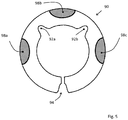
- the ball screw 10 can also include a spring-damping element of the bearing ring (90) at least one pressure element (98) on the outer circumference.
- a spring-damping element of the bearing ring (90) at least one pressure element (98) on the outer circumference.
- the pressing element 98 of the bearing ring 90 can be made of a material that has greater elasticity than the material of the rest of the bearing ring 90, in simplified terms made of a softer plastic.
- the pressing element 98 can advantageously have a radius which deviates positively from the nominal outside diameter.
- the bearing ring is mounted by sliding it onto the first, free end (16) of the threaded spindle.
- the safety can be guaranteed by a flat, flange-like end of the threaded spindle.
- the noise-inhibiting effect of the bearing ring is achieved, among other things, in that the spring-damping element provides a spring-loaded supporting effect between the extension sleeve (15) and the threaded spindle (12).
- the extension sleeve and the threaded spindle no longer vibrate independently, but are supported against each other by the bearing ring. Vibrations of the threaded spindle or the extension sleeve are reduced by the spring-damping element and are not easily transferred to the other component.
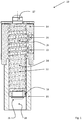
- Figure 1 shows a ball screw 10 in axial longitudinal section.
- the basic components are a threaded spindle 12 and a spindle nut 14 which at least partially surrounds the threaded spindle 12 coaxially.
- the central longitudinal axis of the spindle 12 simultaneously forms the system axis 28.
- the threaded spindle has a helical, circumferential running groove 24 on the outside, similar to the thread of a screw.
- the inside of the spindle nut 14 has an internal thread that is complementary to the threaded spindle 12 and also has an approximately (in cross-section) half-shell-shaped running groove.
- the space between the spindle nut 14 and the threaded spindle 12 is dimensioned in such a way that balls 26 can rotate in the running grooves and thus ensure the relative mobility of the spindle 12 and spindle nut 14 with almost no play.
- two ball deflections 20, 22 are shown, which are responsible for the fact that the balls have an endless circulation. For this purpose, they are lifted out of the running groove at a defined point by a lifting device (not shown here) and reinserted into the space between spindle 12 and spindle nut 14, offset by a few threads.
- the double outer ball deflection shown here can in principle also be replaced by an inner ball deflection without affecting the inventive concept.
- the threaded spindle 12 has a first end 16, which in Figure 1 is drawn as a free end and a second end 17 which is designed to be connected to a drive. If the motor side is selected as the stationary reference system, this means that when the spindle 12 rotates, the spindle nut is displaced axially.
- the translational movement can be transmitted to further actuating or measuring elements by an extension sleeve 15 which coaxially surrounds the threaded spindle and is firmly connected to the spindle nut 12.
- the extension sleeve 15 and the spindle nut 14 could of course be made from one piece.
- the distinction makes the sense that the spindle nut performs the ball screw function, while the extension sleeve 15 does not have an internal thread and therefore cannot accommodate any balls.
- the support and guidance provided by the balls in the space between the spindle nut 14 and the threaded spindle 12 is therefore not available for the area of the extension sleeve 15.
- it makes sense to precisely define the relative position of these two components.
- a simple bearing ring at the first end 16 of the spindle 12 is not sufficient; on the contrary, it can transmit vibrations from one component to another that arise during operation.
- the bearing ring was modified in such a way that the bearing ring 18 serving as a shaft bearing between the threaded spindle 12 and the extension sleeve 15 has at least one integrated spring / damping element that has a noise-inhibiting effect.
- Figure 2 therefore shows a first, simple embodiment according to the present invention.
- the spring-damping element of the bearing ring 30 comprises a combination of at least one notch 32 on the inner circumference of the bearing ring 30 and an annular gap 34.
- FIGs 2-4 it applies that reference symbols that are identified by additional letters are or can be present multiple times. So shows Figure 1 two notches 32a and 32b.
- the spring-damping element 30 can additionally include at least one or more incisions 36 a, b, c on the outer circumference. These additionally support the spring or damping behavior.
- the incisions 36, 56, 76 can be designed differently.
- Figure 2 shows notch-shaped cuts 36 with a u or v profile.
- the depth, measured radially from the outer circumference in the direction of the center point 40, can preferably be 30-60% of the radial, nominal ring width of the bearing ring (30, 50, 70).
- Figures 3 and 4 show an embodiment of the incisions as a slot running radially inward on the outer circumference. This execution could also be in the configuration according to Figure 2 Find application.
- an incision would be considered to be a slot which has essentially the same width over its length.
- the spring-damping element continues the design with the slot 56, 76 running radially inward on the outer circumference. At its radially inner end, a further slot 59, 79 is attached, which is offset by an angle of approximately 90 ° and runs essentially parallel to the outer circumference. It can be curved, in the sense of running strictly parallel to the outer circumference (circular arc) or straight (circular chord) or between these two extremes.
- the length of this addition, the further slot is between 20 ° and 60 °, preferably 40 ° -50 ° in radians.
- the further slot 59, 79 can as in Figure 3 shown to be executed with a uniform width. However, this is not mandatory.
- the course of the width can widen or narrow in the course, in particular the end of this further slot 59, 79 can be designed as semicircular or in the form of drops, similarly Fig. 4 .
- This essentially circular wall has advantages in terms of manufacture and also in terms of its function as a spring element.
- the bearing ring described can preferably be produced in one piece from a thermoplastic by means of injection molding.
- the outer diameter of the bearing ring is 12.4 mm
- the ring width is approx. 2.6 mm
- the depth is approx. 4 mm.
- the dimensions can, however, be adapted to a large extent by scaling up or down without any inventive effort, without losing the inventive features.
- the ones in the Figures 3 and 3 The embodiments shown specifically of the spring / damping element (56, 57, 58, 59, 76, 77, 78, 79) can also be provided several times on the circumference, depending on the dimensions of the bearing ring.
- FIG. 5 Another preferred embodiment of a bearing ring 90 is shown. Incisions 36 on the outer circumference as in Figure 2 or similarly shaped recesses on the outer circumference of a bearing ring 90 are here filled with a material that is more elastic than the material of the actual bearing ring. This is opposite to the execution of Figure 2 avoided that the ring is weakened at the points by the omission of material. At the same time, the elastic material has a resilient effect and thus functions as a damping element. In a preferred variant, the material in the regions 98 can protrude radially outward beyond the outer circumference marked by the actual bearing ring 90, which is analogous to the variant from FIG Figure 4 , helps strengthen the cushioning effect. Such a variant can be produced, for example, by an assembly injection molding process or a multi-stage injection molding process.
Landscapes
- Engineering & Computer Science (AREA)
- General Engineering & Computer Science (AREA)
- Mechanical Engineering (AREA)
- Rolling Contact Bearings (AREA)
- Transmission Devices (AREA)
- Support Of The Bearing (AREA)
Priority Applications (5)
| Application Number | Priority Date | Filing Date | Title |
|---|---|---|---|
| EP17170582.5A EP3401571B1 (de) | 2017-05-11 | 2017-05-11 | Kugelgewindetrieb |
| PL17170582T PL3401571T3 (pl) | 2017-05-11 | 2017-05-11 | Mechanizm śrubowo-toczny |
| ES17170582T ES2884063T3 (es) | 2017-05-11 | 2017-05-11 | Husillo roscado de bolas |
| US15/973,941 US10871211B2 (en) | 2017-05-11 | 2018-05-08 | Ball screw drive |
| CN201810441647.6A CN108869676B (zh) | 2017-05-11 | 2018-05-10 | 滚珠丝杠传动装置 |
Applications Claiming Priority (1)
| Application Number | Priority Date | Filing Date | Title |
|---|---|---|---|
| EP17170582.5A EP3401571B1 (de) | 2017-05-11 | 2017-05-11 | Kugelgewindetrieb |
Publications (2)
| Publication Number | Publication Date |
|---|---|
| EP3401571A1 EP3401571A1 (de) | 2018-11-14 |
| EP3401571B1 true EP3401571B1 (de) | 2021-07-07 |
Family
ID=58701515
Family Applications (1)
| Application Number | Title | Priority Date | Filing Date |
|---|---|---|---|
| EP17170582.5A Active EP3401571B1 (de) | 2017-05-11 | 2017-05-11 | Kugelgewindetrieb |
Country Status (5)
| Country | Link |
|---|---|
| US (1) | US10871211B2 (pl) |
| EP (1) | EP3401571B1 (pl) |
| CN (1) | CN108869676B (pl) |
| ES (1) | ES2884063T3 (pl) |
| PL (1) | PL3401571T3 (pl) |
Families Citing this family (10)
| Publication number | Priority date | Publication date | Assignee | Title |
|---|---|---|---|---|
| DE102018106026A1 (de) * | 2018-03-15 | 2019-09-19 | Thyssenkrupp Ag | Schneckengetriebe mit einem Schwenklager mit definierter Schwenkachse |
| CN111396456B (zh) * | 2019-01-02 | 2021-07-13 | 中国航发商用航空发动机有限责任公司 | 滚动轴承以及支承结构 |
| CN109958734B (zh) * | 2019-02-13 | 2021-06-11 | 绍兴市亿跃智能科技有限公司 | 具有导向的活塞杆 |
| CN111350797A (zh) * | 2020-03-14 | 2020-06-30 | 绍兴集知汇信息科技有限公司 | 一种改进型丝杠螺母 |
| CN111501430B (zh) * | 2020-04-28 | 2021-06-29 | 上海工程技术大学 | 一种以滚珠丝杠组合装置为振子的钢轨吸振器结构 |
| KR102957342B1 (ko) * | 2021-04-26 | 2026-04-28 | 에이치엘만도 주식회사 | 자동차의 조향장치 |
| DE102022106373B4 (de) * | 2022-03-18 | 2023-10-12 | Festo Se & Co. Kg | Linearantrieb |
| DE102022114070A1 (de) * | 2022-06-03 | 2023-12-14 | Schaeffler Technologies AG & Co. KG | Kugelgewindetrieb und elektromechanischer Aktuator |
| CN114876965B (zh) * | 2022-06-17 | 2024-02-20 | 山东朗澈轴承有限公司 | 一种适用于高载荷深沟球轴承套圈组件 |
| CN116906521B (zh) * | 2023-08-30 | 2026-03-10 | 拿森汽车科技(杭州)有限公司 | 丝杆丝母防转机构 |
Family Cites Families (23)
| Publication number | Priority date | Publication date | Assignee | Title |
|---|---|---|---|---|
| US3485110A (en) * | 1968-08-21 | 1969-12-23 | Duff Norton Co | Nut and screw mechanism |
| US4137784A (en) * | 1977-11-14 | 1979-02-06 | Industrial Device Corporation | Electromechanical equivalent of fluid powered cylinder |
| US5046402A (en) * | 1990-04-23 | 1991-09-10 | Lagace Jean Hugues | Rotary to axial motion converting device with groove in piston guide |
| JP2001124175A (ja) * | 1999-10-29 | 2001-05-08 | Iai:Kk | アクチュエータ |
| US20050160846A1 (en) * | 2004-01-20 | 2005-07-28 | Yi-Chung Chiang | Linear actuator |
| JP4574228B2 (ja) * | 2004-05-17 | 2010-11-04 | Ntn株式会社 | 電動アクチュエータ用ボールねじ |
| DE112007001625T5 (de) * | 2006-07-12 | 2009-04-30 | Hitachi Ltd. | Servolenkungssystem, Drehzahlverringerungseinrichtung und Lagerhaltung |
| TWI426685B (zh) * | 2008-04-17 | 2014-02-11 | Smc Kk | 電動致動器 |
| DE102010054134B3 (de) * | 2010-12-10 | 2012-04-12 | Thyssenkrupp Presta Ag | Kugelgewindetrieb |
| JP5918519B2 (ja) * | 2011-07-13 | 2016-05-18 | 株式会社アイエイアイ | アクチュエータ |
| JP5845070B2 (ja) * | 2011-12-01 | 2016-01-20 | 株式会社アイエイアイ | アクチュエータ |
| TWM470445U (zh) * | 2012-12-10 | 2014-01-11 | Star Motor Ind Co Ltd J | 線性致動器 |
| TWM457478U (zh) * | 2012-12-25 | 2013-07-21 | Kelly Internat Corp | 螺桿昇降之防下滑裝置 |
| DE102013003830B4 (de) * | 2013-03-07 | 2026-02-05 | Brose Fahrzeugteile Se & Co. Kommanditgesellschaft, Bamberg | Spindelantrieb für ein Verstellelement eines Kraftfahrzeugs |
| TWM459317U (zh) * | 2013-03-28 | 2013-08-11 | Timotion Technology Co Ltd | 具雙螺桿之線性傳動裝置 |
| JP6486609B2 (ja) * | 2014-05-14 | 2019-03-20 | 株式会社ハイレックスコーポレーション | 開閉体開閉装置 |
| DE102015004018A1 (de) * | 2015-03-25 | 2016-09-29 | Kiekert Aktiengesellschaft | Zuziehantrieb für ein Kraftfahrzeugschloss |
| FR3050493B1 (fr) * | 2016-04-26 | 2018-05-25 | Foundation Brakes France Sas | Ecrou a faible prix de revient pour systeme de freinage de vehicule |
| EP3499070B1 (en) * | 2016-08-08 | 2020-02-19 | NSK Ltd. | Joint for torque transmission, and electric power steering device |
| CN205896353U (zh) * | 2016-08-17 | 2017-01-18 | 浙江征天机械制造有限公司 | 一种用于启闭机的推杆总成装置 |
| CN205896076U (zh) * | 2016-08-25 | 2017-01-18 | 浙江联宜电机有限公司 | 电动推杆丝杆支撑固定结构 |
| KR102591716B1 (ko) * | 2016-10-31 | 2023-10-23 | 현대모비스 주식회사 | 전동식 조향장치 |
| JP7067149B2 (ja) * | 2018-03-13 | 2022-05-16 | 株式会社アイシン | 車両用ドア開閉装置 |
-
2017
- 2017-05-11 PL PL17170582T patent/PL3401571T3/pl unknown
- 2017-05-11 ES ES17170582T patent/ES2884063T3/es active Active
- 2017-05-11 EP EP17170582.5A patent/EP3401571B1/de active Active
-
2018
- 2018-05-08 US US15/973,941 patent/US10871211B2/en active Active
- 2018-05-10 CN CN201810441647.6A patent/CN108869676B/zh active Active
Also Published As
| Publication number | Publication date |
|---|---|
| PL3401571T3 (pl) | 2021-12-06 |
| US10871211B2 (en) | 2020-12-22 |
| CN108869676A (zh) | 2018-11-23 |
| CN108869676B (zh) | 2023-09-08 |
| US20180328472A1 (en) | 2018-11-15 |
| ES2884063T3 (es) | 2021-12-10 |
| EP3401571A1 (de) | 2018-11-14 |
Similar Documents
| Publication | Publication Date | Title |
|---|---|---|
| EP3401571A1 (de) | Kugelgewindetrieb | |
| EP0392146B1 (de) | Wälzlagerkäfig | |
| DE3249692C2 (pl) | ||
| WO2011113724A1 (de) | Planetenwälzgewindetrieb | |
| DE102010021536B4 (de) | Spindelantrieb | |
| DE102019103384A1 (de) | Planetenwälzgewindetrieb | |
| EP4269830B1 (de) | Käfigfreilauf mit klemmstücken und lagerrollen | |
| DE102007039733B4 (de) | Lenkeinrichtung mit Anschlagbegrenzung | |
| DE102011003562A1 (de) | Kugelgewindetrieb und damit ausgestattete Lenkeinrichtung | |
| DE102019125310A1 (de) | Planetenwälzgetriebe | |
| WO2017211514A1 (de) | Aktuator mit einem schublager für eine spindel sowie aktuator für eine hinterachslenkung | |
| EP0177682A2 (de) | Überlastkupplung, insbesondere für Gewindeschneidfutter oder dergleichen | |
| DE10301082B4 (de) | Wälzlager für Linearbewegungen | |
| DE102009038735B4 (de) | Verstellvorrichtung für eine Fahrzeugkomponente | |
| DE102018216781A1 (de) | Dichtelement, Spindelantrieb und Aktuator einer Lenkung mit Spindelantrieb | |
| DE2630656C3 (de) | Selbstzentrierendes Ausrücklager für Kupplungen, insbesondere Kraftfahrzeugkupplungen | |
| WO2018192611A1 (de) | Gewindespindel und verfahren zur herstellung einer gewindespindel | |
| EP3106698A1 (de) | Mechanisches getriebe mit integrierter lastmomentsperre | |
| EP0773381A2 (de) | Kupplungsfederelement | |
| EP0430954B1 (de) | Vorrichtung zur erzeugung einer vorzugsweise steuerbaren axialen gegenkraft an einer durch eine axialkraft axial verschiebbaren rotierenden welle | |
| DE102022120854B4 (de) | Lageranordnung umfassend einen Rotations-Translations-Konverter, insbesondere für eine Bremseinrichtung, sowie Linearstelleinrichtung | |
| EP3500776B1 (de) | Spindelantrieb mit überlastkupplung | |
| EP1126193B1 (de) | Wälzkörpergewindetrieb und Verfahren zu dessen Montage | |
| DE102016201100A1 (de) | Gleitlagerring und Aktuator mit Gleitlagerring | |
| DE102022120853B4 (de) | Lageranordnung mit Axiallagerscheibe |
Legal Events
| Date | Code | Title | Description |
|---|---|---|---|
| PUAI | Public reference made under article 153(3) epc to a published international application that has entered the european phase |
Free format text: ORIGINAL CODE: 0009012 |
|
| STAA | Information on the status of an ep patent application or granted ep patent |
Free format text: STATUS: THE APPLICATION HAS BEEN PUBLISHED |
|
| AK | Designated contracting states |
Kind code of ref document: A1 Designated state(s): AL AT BE BG CH CY CZ DE DK EE ES FI FR GB GR HR HU IE IS IT LI LT LU LV MC MK MT NL NO PL PT RO RS SE SI SK SM TR |
|
| AX | Request for extension of the european patent |
Extension state: BA ME |
|
| RAP1 | Party data changed (applicant data changed or rights of an application transferred) |
Owner name: SFS INTEC HOLDING AG |
|
| STAA | Information on the status of an ep patent application or granted ep patent |
Free format text: STATUS: REQUEST FOR EXAMINATION WAS MADE |
|
| 17P | Request for examination filed |
Effective date: 20190514 |
|
| RBV | Designated contracting states (corrected) |
Designated state(s): AL AT BE BG CH CY CZ DE DK EE ES FI FR GB GR HR HU IE IS IT LI LT LU LV MC MK MT NL NO PL PT RO RS SE SI SK SM TR |
|
| RIC1 | Information provided on ipc code assigned before grant |
Ipc: F16H 25/20 20060101ALN20201217BHEP Ipc: F16H 25/24 20060101AFI20201217BHEP Ipc: F16H 25/22 20060101ALI20201217BHEP Ipc: F16F 9/32 20060101ALN20201217BHEP Ipc: F16C 29/00 20060101ALN20201217BHEP |
|
| GRAP | Despatch of communication of intention to grant a patent |
Free format text: ORIGINAL CODE: EPIDOSNIGR1 |
|
| STAA | Information on the status of an ep patent application or granted ep patent |
Free format text: STATUS: GRANT OF PATENT IS INTENDED |
|
| INTG | Intention to grant announced |
Effective date: 20210129 |
|
| GRAS | Grant fee paid |
Free format text: ORIGINAL CODE: EPIDOSNIGR3 |
|
| GRAA | (expected) grant |
Free format text: ORIGINAL CODE: 0009210 |
|
| STAA | Information on the status of an ep patent application or granted ep patent |
Free format text: STATUS: THE PATENT HAS BEEN GRANTED |
|
| AK | Designated contracting states |
Kind code of ref document: B1 Designated state(s): AL AT BE BG CH CY CZ DE DK EE ES FI FR GB GR HR HU IE IS IT LI LT LU LV MC MK MT NL NO PL PT RO RS SE SI SK SM TR |
|
| REG | Reference to a national code |
Ref country code: GB Ref legal event code: FG4D Free format text: NOT ENGLISH |
|
| REG | Reference to a national code |
Ref country code: AT Ref legal event code: REF Ref document number: 1408889 Country of ref document: AT Kind code of ref document: T Effective date: 20210715 |
|
| REG | Reference to a national code |
Ref country code: DE Ref legal event code: R096 Ref document number: 502017010824 Country of ref document: DE |
|
| REG | Reference to a national code |
Ref country code: IE Ref legal event code: FG4D Free format text: LANGUAGE OF EP DOCUMENT: GERMAN |
|
| REG | Reference to a national code |
Ref country code: RO Ref legal event code: EPE |
|
| REG | Reference to a national code |
Ref country code: LT Ref legal event code: MG9D |
|
| REG | Reference to a national code |
Ref country code: SE Ref legal event code: TRGR |
|
| REG | Reference to a national code |
Ref country code: NL Ref legal event code: MP Effective date: 20210707 |
|
| REG | Reference to a national code |
Ref country code: ES Ref legal event code: FG2A Ref document number: 2884063 Country of ref document: ES Kind code of ref document: T3 Effective date: 20211210 |
|
| PG25 | Lapsed in a contracting state [announced via postgrant information from national office to epo] |
Ref country code: RS Free format text: LAPSE BECAUSE OF FAILURE TO SUBMIT A TRANSLATION OF THE DESCRIPTION OR TO PAY THE FEE WITHIN THE PRESCRIBED TIME-LIMIT Effective date: 20210707 Ref country code: FI Free format text: LAPSE BECAUSE OF FAILURE TO SUBMIT A TRANSLATION OF THE DESCRIPTION OR TO PAY THE FEE WITHIN THE PRESCRIBED TIME-LIMIT Effective date: 20210707 Ref country code: HR Free format text: LAPSE BECAUSE OF FAILURE TO SUBMIT A TRANSLATION OF THE DESCRIPTION OR TO PAY THE FEE WITHIN THE PRESCRIBED TIME-LIMIT Effective date: 20210707 Ref country code: NO Free format text: LAPSE BECAUSE OF FAILURE TO SUBMIT A TRANSLATION OF THE DESCRIPTION OR TO PAY THE FEE WITHIN THE PRESCRIBED TIME-LIMIT Effective date: 20211007 Ref country code: PT Free format text: LAPSE BECAUSE OF FAILURE TO SUBMIT A TRANSLATION OF THE DESCRIPTION OR TO PAY THE FEE WITHIN THE PRESCRIBED TIME-LIMIT Effective date: 20211108 Ref country code: NL Free format text: LAPSE BECAUSE OF FAILURE TO SUBMIT A TRANSLATION OF THE DESCRIPTION OR TO PAY THE FEE WITHIN THE PRESCRIBED TIME-LIMIT Effective date: 20210707 Ref country code: LT Free format text: LAPSE BECAUSE OF FAILURE TO SUBMIT A TRANSLATION OF THE DESCRIPTION OR TO PAY THE FEE WITHIN THE PRESCRIBED TIME-LIMIT Effective date: 20210707 Ref country code: BG Free format text: LAPSE BECAUSE OF FAILURE TO SUBMIT A TRANSLATION OF THE DESCRIPTION OR TO PAY THE FEE WITHIN THE PRESCRIBED TIME-LIMIT Effective date: 20211007 |
|
| PG25 | Lapsed in a contracting state [announced via postgrant information from national office to epo] |
Ref country code: LV Free format text: LAPSE BECAUSE OF FAILURE TO SUBMIT A TRANSLATION OF THE DESCRIPTION OR TO PAY THE FEE WITHIN THE PRESCRIBED TIME-LIMIT Effective date: 20210707 Ref country code: GR Free format text: LAPSE BECAUSE OF FAILURE TO SUBMIT A TRANSLATION OF THE DESCRIPTION OR TO PAY THE FEE WITHIN THE PRESCRIBED TIME-LIMIT Effective date: 20211008 |
|
| RAP4 | Party data changed (patent owner data changed or rights of a patent transferred) |
Owner name: SFS GROUP INTERNATIONAL AG |
|
| REG | Reference to a national code |
Ref country code: DE Ref legal event code: R097 Ref document number: 502017010824 Country of ref document: DE |
|
| PG25 | Lapsed in a contracting state [announced via postgrant information from national office to epo] |
Ref country code: DK Free format text: LAPSE BECAUSE OF FAILURE TO SUBMIT A TRANSLATION OF THE DESCRIPTION OR TO PAY THE FEE WITHIN THE PRESCRIBED TIME-LIMIT Effective date: 20210707 |
|
| PLBE | No opposition filed within time limit |
Free format text: ORIGINAL CODE: 0009261 |
|
| STAA | Information on the status of an ep patent application or granted ep patent |
Free format text: STATUS: NO OPPOSITION FILED WITHIN TIME LIMIT |
|
| PG25 | Lapsed in a contracting state [announced via postgrant information from national office to epo] |
Ref country code: SM Free format text: LAPSE BECAUSE OF FAILURE TO SUBMIT A TRANSLATION OF THE DESCRIPTION OR TO PAY THE FEE WITHIN THE PRESCRIBED TIME-LIMIT Effective date: 20210707 Ref country code: SK Free format text: LAPSE BECAUSE OF FAILURE TO SUBMIT A TRANSLATION OF THE DESCRIPTION OR TO PAY THE FEE WITHIN THE PRESCRIBED TIME-LIMIT Effective date: 20210707 Ref country code: EE Free format text: LAPSE BECAUSE OF FAILURE TO SUBMIT A TRANSLATION OF THE DESCRIPTION OR TO PAY THE FEE WITHIN THE PRESCRIBED TIME-LIMIT Effective date: 20210707 Ref country code: AL Free format text: LAPSE BECAUSE OF FAILURE TO SUBMIT A TRANSLATION OF THE DESCRIPTION OR TO PAY THE FEE WITHIN THE PRESCRIBED TIME-LIMIT Effective date: 20210707 |
|
| 26N | No opposition filed |
Effective date: 20220408 |
|
| REG | Reference to a national code |
Ref country code: BE Ref legal event code: MM Effective date: 20220531 |
|
| PG25 | Lapsed in a contracting state [announced via postgrant information from national office to epo] |
Ref country code: MC Free format text: LAPSE BECAUSE OF FAILURE TO SUBMIT A TRANSLATION OF THE DESCRIPTION OR TO PAY THE FEE WITHIN THE PRESCRIBED TIME-LIMIT Effective date: 20210707 Ref country code: LU Free format text: LAPSE BECAUSE OF NON-PAYMENT OF DUE FEES Effective date: 20220511 |
|
| PG25 | Lapsed in a contracting state [announced via postgrant information from national office to epo] |
Ref country code: IE Free format text: LAPSE BECAUSE OF NON-PAYMENT OF DUE FEES Effective date: 20220511 |
|
| PG25 | Lapsed in a contracting state [announced via postgrant information from national office to epo] |
Ref country code: BE Free format text: LAPSE BECAUSE OF NON-PAYMENT OF DUE FEES Effective date: 20220531 |
|
| P01 | Opt-out of the competence of the unified patent court (upc) registered |
Effective date: 20230622 |
|
| PG25 | Lapsed in a contracting state [announced via postgrant information from national office to epo] |
Ref country code: HU Free format text: LAPSE BECAUSE OF FAILURE TO SUBMIT A TRANSLATION OF THE DESCRIPTION OR TO PAY THE FEE WITHIN THE PRESCRIBED TIME-LIMIT; INVALID AB INITIO Effective date: 20170511 |
|
| PG25 | Lapsed in a contracting state [announced via postgrant information from national office to epo] |
Ref country code: MK Free format text: LAPSE BECAUSE OF FAILURE TO SUBMIT A TRANSLATION OF THE DESCRIPTION OR TO PAY THE FEE WITHIN THE PRESCRIBED TIME-LIMIT Effective date: 20210707 Ref country code: CY Free format text: LAPSE BECAUSE OF FAILURE TO SUBMIT A TRANSLATION OF THE DESCRIPTION OR TO PAY THE FEE WITHIN THE PRESCRIBED TIME-LIMIT Effective date: 20210707 |
|
| PG25 | Lapsed in a contracting state [announced via postgrant information from national office to epo] |
Ref country code: TR Free format text: LAPSE BECAUSE OF FAILURE TO SUBMIT A TRANSLATION OF THE DESCRIPTION OR TO PAY THE FEE WITHIN THE PRESCRIBED TIME-LIMIT Effective date: 20210707 |
|
| PG25 | Lapsed in a contracting state [announced via postgrant information from national office to epo] |
Ref country code: MT Free format text: LAPSE BECAUSE OF FAILURE TO SUBMIT A TRANSLATION OF THE DESCRIPTION OR TO PAY THE FEE WITHIN THE PRESCRIBED TIME-LIMIT Effective date: 20210707 |
|
| PGFP | Annual fee paid to national office [announced via postgrant information from national office to epo] |
Ref country code: PL Payment date: 20250429 Year of fee payment: 9 Ref country code: DE Payment date: 20250519 Year of fee payment: 9 |
|
| PGFP | Annual fee paid to national office [announced via postgrant information from national office to epo] |
Ref country code: ES Payment date: 20250616 Year of fee payment: 9 Ref country code: GB Payment date: 20250522 Year of fee payment: 9 |
|
| PGFP | Annual fee paid to national office [announced via postgrant information from national office to epo] |
Ref country code: IT Payment date: 20250530 Year of fee payment: 9 |
|
| PGFP | Annual fee paid to national office [announced via postgrant information from national office to epo] |
Ref country code: FR Payment date: 20250521 Year of fee payment: 9 |
|
| PGFP | Annual fee paid to national office [announced via postgrant information from national office to epo] |
Ref country code: CH Payment date: 20250601 Year of fee payment: 9 |
|
| PGFP | Annual fee paid to national office [announced via postgrant information from national office to epo] |
Ref country code: RO Payment date: 20250430 Year of fee payment: 9 Ref country code: AT Payment date: 20250519 Year of fee payment: 9 |
|
| PGFP | Annual fee paid to national office [announced via postgrant information from national office to epo] |
Ref country code: CZ Payment date: 20250428 Year of fee payment: 9 |
|
| PGFP | Annual fee paid to national office [announced via postgrant information from national office to epo] |
Ref country code: SE Payment date: 20250522 Year of fee payment: 9 |