EP3401571A1 - Kugelgewindetrieb - Google Patents
Kugelgewindetrieb Download PDFInfo
- Publication number
- EP3401571A1 EP3401571A1 EP17170582.5A EP17170582A EP3401571A1 EP 3401571 A1 EP3401571 A1 EP 3401571A1 EP 17170582 A EP17170582 A EP 17170582A EP 3401571 A1 EP3401571 A1 EP 3401571A1
- Authority
- EP
- European Patent Office
- Prior art keywords
- bearing ring
- ball screw
- threaded spindle
- spindle
- outer circumference
- Prior art date
- Legal status (The legal status is an assumption and is not a legal conclusion. Google has not performed a legal analysis and makes no representation as to the accuracy of the status listed.)
- Granted
Links
- 238000013016 damping Methods 0.000 claims abstract description 23
- 230000002401 inhibitory effect Effects 0.000 claims abstract description 4
- 239000000463 material Substances 0.000 claims description 13
- 239000012815 thermoplastic material Substances 0.000 claims description 3
- 230000000694 effects Effects 0.000 description 8
- 238000001746 injection moulding Methods 0.000 description 3
- 238000004519 manufacturing process Methods 0.000 description 2
- 238000005096 rolling process Methods 0.000 description 2
- 230000000295 complement effect Effects 0.000 description 1
- 239000013013 elastic material Substances 0.000 description 1
- 238000007373 indentation Methods 0.000 description 1
- 230000000670 limiting effect Effects 0.000 description 1
- 238000011089 mechanical engineering Methods 0.000 description 1
- 239000004033 plastic Substances 0.000 description 1
- 230000002829 reductive effect Effects 0.000 description 1
- 230000003068 static effect Effects 0.000 description 1
- 210000002435 tendon Anatomy 0.000 description 1
Images


Classifications
-
- F—MECHANICAL ENGINEERING; LIGHTING; HEATING; WEAPONS; BLASTING
- F16—ENGINEERING ELEMENTS AND UNITS; GENERAL MEASURES FOR PRODUCING AND MAINTAINING EFFECTIVE FUNCTIONING OF MACHINES OR INSTALLATIONS; THERMAL INSULATION IN GENERAL
- F16H—GEARING
- F16H25/00—Gearings comprising primarily only cams, cam-followers and screw-and-nut mechanisms
- F16H25/18—Gearings comprising primarily only cams, cam-followers and screw-and-nut mechanisms for conveying or interconverting oscillating or reciprocating motions
- F16H25/20—Screw mechanisms
- F16H25/24—Elements essential to such mechanisms, e.g. screws, nuts
-
- F—MECHANICAL ENGINEERING; LIGHTING; HEATING; WEAPONS; BLASTING
- F16—ENGINEERING ELEMENTS AND UNITS; GENERAL MEASURES FOR PRODUCING AND MAINTAINING EFFECTIVE FUNCTIONING OF MACHINES OR INSTALLATIONS; THERMAL INSULATION IN GENERAL
- F16C—SHAFTS; FLEXIBLE SHAFTS; ELEMENTS OR CRANKSHAFT MECHANISMS; ROTARY BODIES OTHER THAN GEARING ELEMENTS; BEARINGS
- F16C33/00—Parts of bearings; Special methods for making bearings or parts thereof
- F16C33/30—Parts of ball or roller bearings
- F16C33/58—Raceways; Race rings
- F16C33/581—Raceways; Race rings integral with other parts, e.g. with housings or machine elements such as shafts or gear wheels
-
- F—MECHANICAL ENGINEERING; LIGHTING; HEATING; WEAPONS; BLASTING
- F16—ENGINEERING ELEMENTS AND UNITS; GENERAL MEASURES FOR PRODUCING AND MAINTAINING EFFECTIVE FUNCTIONING OF MACHINES OR INSTALLATIONS; THERMAL INSULATION IN GENERAL
- F16H—GEARING
- F16H25/00—Gearings comprising primarily only cams, cam-followers and screw-and-nut mechanisms
- F16H25/18—Gearings comprising primarily only cams, cam-followers and screw-and-nut mechanisms for conveying or interconverting oscillating or reciprocating motions
- F16H25/20—Screw mechanisms
- F16H25/22—Screw mechanisms with balls, rollers, or similar members between the co-operating parts; Elements essential to the use of such members
- F16H25/2204—Screw mechanisms with balls, rollers, or similar members between the co-operating parts; Elements essential to the use of such members with balls
- F16H25/2214—Screw mechanisms with balls, rollers, or similar members between the co-operating parts; Elements essential to the use of such members with balls with elements for guiding the circulating balls
-
- F—MECHANICAL ENGINEERING; LIGHTING; HEATING; WEAPONS; BLASTING
- F16—ENGINEERING ELEMENTS AND UNITS; GENERAL MEASURES FOR PRODUCING AND MAINTAINING EFFECTIVE FUNCTIONING OF MACHINES OR INSTALLATIONS; THERMAL INSULATION IN GENERAL
- F16H—GEARING
- F16H57/00—General details of gearing
- F16H57/0006—Vibration-damping or noise reducing means specially adapted for gearings
-
- F—MECHANICAL ENGINEERING; LIGHTING; HEATING; WEAPONS; BLASTING
- F16—ENGINEERING ELEMENTS AND UNITS; GENERAL MEASURES FOR PRODUCING AND MAINTAINING EFFECTIVE FUNCTIONING OF MACHINES OR INSTALLATIONS; THERMAL INSULATION IN GENERAL
- F16C—SHAFTS; FLEXIBLE SHAFTS; ELEMENTS OR CRANKSHAFT MECHANISMS; ROTARY BODIES OTHER THAN GEARING ELEMENTS; BEARINGS
- F16C29/00—Bearings for parts moving only linearly
- F16C29/002—Elastic or yielding linear bearings or bearing supports
-
- F—MECHANICAL ENGINEERING; LIGHTING; HEATING; WEAPONS; BLASTING
- F16—ENGINEERING ELEMENTS AND UNITS; GENERAL MEASURES FOR PRODUCING AND MAINTAINING EFFECTIVE FUNCTIONING OF MACHINES OR INSTALLATIONS; THERMAL INSULATION IN GENERAL
- F16C—SHAFTS; FLEXIBLE SHAFTS; ELEMENTS OR CRANKSHAFT MECHANISMS; ROTARY BODIES OTHER THAN GEARING ELEMENTS; BEARINGS
- F16C29/00—Bearings for parts moving only linearly
- F16C29/02—Sliding-contact bearings
-
- F—MECHANICAL ENGINEERING; LIGHTING; HEATING; WEAPONS; BLASTING
- F16—ENGINEERING ELEMENTS AND UNITS; GENERAL MEASURES FOR PRODUCING AND MAINTAINING EFFECTIVE FUNCTIONING OF MACHINES OR INSTALLATIONS; THERMAL INSULATION IN GENERAL
- F16F—SPRINGS; SHOCK-ABSORBERS; MEANS FOR DAMPING VIBRATION
- F16F1/00—Springs
- F16F1/36—Springs made of rubber or other material having high internal friction, e.g. thermoplastic elastomers
- F16F1/373—Springs made of rubber or other material having high internal friction, e.g. thermoplastic elastomers characterised by having a particular shape
- F16F1/3732—Springs made of rubber or other material having high internal friction, e.g. thermoplastic elastomers characterised by having a particular shape having an annular or the like shape, e.g. grommet-type resilient mountings
-
- F—MECHANICAL ENGINEERING; LIGHTING; HEATING; WEAPONS; BLASTING
- F16—ENGINEERING ELEMENTS AND UNITS; GENERAL MEASURES FOR PRODUCING AND MAINTAINING EFFECTIVE FUNCTIONING OF MACHINES OR INSTALLATIONS; THERMAL INSULATION IN GENERAL
- F16F—SPRINGS; SHOCK-ABSORBERS; MEANS FOR DAMPING VIBRATION
- F16F1/00—Springs
- F16F1/36—Springs made of rubber or other material having high internal friction, e.g. thermoplastic elastomers
- F16F1/373—Springs made of rubber or other material having high internal friction, e.g. thermoplastic elastomers characterised by having a particular shape
- F16F1/376—Springs made of rubber or other material having high internal friction, e.g. thermoplastic elastomers characterised by having a particular shape having projections, studs, serrations or the like on at least one surface
-
- F—MECHANICAL ENGINEERING; LIGHTING; HEATING; WEAPONS; BLASTING
- F16—ENGINEERING ELEMENTS AND UNITS; GENERAL MEASURES FOR PRODUCING AND MAINTAINING EFFECTIVE FUNCTIONING OF MACHINES OR INSTALLATIONS; THERMAL INSULATION IN GENERAL
- F16F—SPRINGS; SHOCK-ABSORBERS; MEANS FOR DAMPING VIBRATION
- F16F9/00—Springs, vibration-dampers, shock-absorbers, or similarly-constructed movement-dampers using a fluid or the equivalent as damping medium
- F16F9/32—Details
-
- F—MECHANICAL ENGINEERING; LIGHTING; HEATING; WEAPONS; BLASTING
- F16—ENGINEERING ELEMENTS AND UNITS; GENERAL MEASURES FOR PRODUCING AND MAINTAINING EFFECTIVE FUNCTIONING OF MACHINES OR INSTALLATIONS; THERMAL INSULATION IN GENERAL
- F16H—GEARING
- F16H25/00—Gearings comprising primarily only cams, cam-followers and screw-and-nut mechanisms
- F16H25/18—Gearings comprising primarily only cams, cam-followers and screw-and-nut mechanisms for conveying or interconverting oscillating or reciprocating motions
- F16H25/20—Screw mechanisms
- F16H2025/204—Axial sliding means, i.e. for rotary support and axial guiding of nut or screw shaft
-
- F—MECHANICAL ENGINEERING; LIGHTING; HEATING; WEAPONS; BLASTING
- F16—ENGINEERING ELEMENTS AND UNITS; GENERAL MEASURES FOR PRODUCING AND MAINTAINING EFFECTIVE FUNCTIONING OF MACHINES OR INSTALLATIONS; THERMAL INSULATION IN GENERAL
- F16H—GEARING
- F16H25/00—Gearings comprising primarily only cams, cam-followers and screw-and-nut mechanisms
- F16H25/18—Gearings comprising primarily only cams, cam-followers and screw-and-nut mechanisms for conveying or interconverting oscillating or reciprocating motions
- F16H25/20—Screw mechanisms
- F16H25/24—Elements essential to such mechanisms, e.g. screws, nuts
- F16H2025/2445—Supports or other means for compensating misalignment or offset between screw and nut
Definitions
- the present invention is concerned with a ball screw whose threaded spindle has a noise-inhibiting bearing at one end.
- a KGT works as a helical gear, the lower or translation is determined by the dimensioning of the threaded spindle, more precisely by the pitch of the thread.
- Ball screws are used in many technical applications, especially in mechanical engineering and preferably in machine tools.
- KGTs are also used as longitudinal drives in areas where previously mostly hydraulic systems were used, e.g. in presses, injection molding machines and power steering systems.
- KGT also play an increasing role in electromechanical and electrohydraulic braking systems.
- brake pressure is to be built up independently of or in support of the driver's brake application.
- the driver's brake signal or a vehicle safety system eg collision warning, ABS sensor system
- the driver's brake signal or a vehicle safety system is evaluated electronically and transmitted as a system response to an electric motor.
- Whose rotational movement acts by the KGT translated into a translational movement. This in turn can move a brake piston and thereby, in particular hydraulically, to build up a brake pressure in one or more brake circuits or directly exert a braking effect (for example, pressing a brake pad onto a brake disk).
- a KGT consists of a threaded spindle and a spindle nut enclosing it.
- the thread of spindle and spindle nut is designed as a raceway for balls.
- the balls rotating in the threads between the spindle and the nut ideally touch (ie play-free) both flanks of the thread at one point each (gothic groove).
- the spindle nut (more rarely the threaded spindle) is also equipped with a ball deflection, which lifts the balls out of the raceway groove at a defined point and returns them to a thread at a different point via a return channel, whereby a closed ball circulation is achieved.
- the translatory movement can be effected by the spindle or by the nut, depending on which component is driven and which is linearly guided.
- the present invention solves this problem by a spring or damping element in the bearing ring, said bearing ring is arranged in the intermediate space between the threaded spindle and extension sleeve.
- Such a ball screw (10) comprises a threaded spindle (12) having a first, free end (16) and a second end (17), which can be connected to a drive, and a spindle nut (14), the threaded spindle (12) Coaxially encloses at least partially, wherein a plurality of balls (26) in the space between the threaded spindle (12) and the spindle nut (14) rotate.
- An extension sleeve (15) connects coaxially to the spindle nut (14) and is firmly connected to it. Consequently, it is movable with it relative to the threaded spindle (12).
- At the first end (16) on the outer circumference of the threaded spindle (12) has a substantially circular bearing ring (18, 30, 50, 70) attached, which serves as a shaft bearing between the threaded spindle (12) and the extension sleeve (15) and by at least one integrated spring / damping element unfolds a sound-inhibiting effect.
- the bearing ring is hereby secured on or on the first end of the threaded spindle so that it can move with play, in particular rotate, but can not slip from the threaded spindle.
- the spring-damping element of the bearing ring (30, 50, 70) comprises a combination of at least one notch (32, 52, 72) on the inner circumference of the bearing ring (30, 50, 70) and an annular gap (34, 54, 74).
- the spring-damping element is a constructive feature of the bearing ring or a combination of individual technical features.
- indentation is meant a recess, a pocket, a cutout, which weakens the material of the bearing ring radially from the inside to the outside at one point, without the bearing ring completely to interrupt.
- the notch can be made as a straight slot or V- or U-shaped recess.
- the annular gap is designed so that the gap is at its narrowest point between 0.1 mm to 0.8 mm (in the state mounted on the spindle) ,
- the annular gap (34, 54, 74) in this case need not be designed as a straight, radial slot, but may be executed edge-rounded or wedge-shaped.
- the ball screw drive (10) may have a spring damping element of the bearing ring (30, 50, 70), which additionally comprises at least one notch (36, 56, 76) on the outer circumference.
- a notch is meant a notch, a recess, a pocket, which weakens the material of the bearing ring radially from outside to inside at one point without completely interrupting the bearing ring.
- the incision can be made as a straight slot or v- or U-shaped recess.
- the incision (36, 56, 76) on the outer circumference is designed as a radially inwardly extending slot whose depth, measured from the outer circumference, 30-60% of the radial nominal ring width of the bearing ring (30, 50, 70) is.
- the incision or slot (36, 56, 76) has a substantially equal width over its length. This corresponds to the o.a. Version as a straight, even, substantially radial slot.
- a (further) slot (59, 79) adjoins the radially inner end of the one cut (56, 76), viewed from the center (60, 80) of the bearing ring (50, 70) Substantially follows the course of a circular arc or a chord and at an angle of 20 ° to 60 °, preferably 40 ° -50 ° appears.
- the bearing ring has a substantially L-shaped in axial plan view incision, wherein the radial component is formed by the above-described notch on the outer circumference, which adjoins an incision or notch in an approximately right angle, the course as a circular arc or Circular tendon can be described.
- the length of the further slot (59, 79) is best described as the angle at which, viewed radially outwards from the axial center of the bearing ring, this further slot (59, 79) appears.
- the further slot (59, 79) may have a non-constant width in its course and, in particular, at its end remote from the incision (56, 76) shows a substantially circular course of the slot wall.
- running as a circular arc or chord in the bearing ring slot has at its end a teardrop-shaped expansion.
- the L-shaped cut gives the spring / damping element the shape of a tongue. From the recess (56, 76), from the further slot (59, 79) and from the outer circumference of the bearing ring (50, 70), a piece of material is defined, which forms a pressing element (58, 78) with a resilient tongue (57, 77).
- the contact pressure element (58, 78) can have a radius which deviates positively from the nominal outside diameter. This means that the nominal diameter of the bearing ring in the region of the resilient tongue is slightly larger. Due to the spring action of the tongue, however, this elevation can be pressed radially inwards so that, under tension, the nominal outer diameter of the bearing ring is achieved.
- the bearing ring (18, 30, 50, 70) can be integrally molded from a thermoplastic material.
- the ball screw 10 may additionally include a spring damping element of the bearing ring (90) at least one pressing element (98) on the outer circumference.
- a spring damping element of the bearing ring (90) at least one pressing element (98) on the outer circumference.
- FIG. 5 shown.
- a region or a volume of material is provided on the outer circumference, which acts as a pressing element.
- the pressure element 98 of the bearing ring 90 is made of a material which has greater elasticity than the material of the rest of the bearing ring 90, in simple terms of a softer plastic.
- the pressing element 98 can advantageously have a radius that differs from the nominal outer diameter.
- the mounting of the bearing ring is done by sliding on the first, free end (16) of the threaded spindle.
- the fuse can be ensured by a flat, flange-like termination of the threaded spindle.
- the anti-noise effect of the bearing is achieved, inter alia, that a spring-loaded support effect between the extension sleeve (15) and the threaded spindle (12) is achieved by the spring-damping element.
- the extension sleeve as well as the threaded spindle no longer vibrate independently but are supported by the bearing ring against each other. Vibrations of the threaded spindle or the extension sleeve are reduced by the spring-damping element and not easily transferred to the other component.
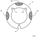
- FIG. 1 shows a ball screw 10 in axial longitudinal section.
- the basic components are a threaded spindle 12 and a spindle nut 14, which surrounds the threaded spindle 12 coaxially at least partially.
- the central longitudinal axis of the spindle 12 simultaneously forms the system axis 28.
- the threaded spindle has on the outside a helical, circumferential groove 24, similar to the thread of a screw.
- the spindle nut 14 has on its inside a complementary to the threaded spindle 12 internal thread with a likewise approximately (in cross-section) half-shell-shaped groove.
- the space between the spindle nut 14 and threaded spindle 12 is dimensioned so that balls 26 can rotate in the grooves and thus ensure the almost play-free relative mobility of the spindle 12 and spindle nut 14.
- the responsible for ensuring that the balls have an endless circulation For this purpose, they are lifted at a defined position by a (not shown here) lifting device from the raceway and offset by a few threads again inserted into the space between the spindle 12 and spindle nut 14.
- the two-fold, external ball deflection shown here can in principle also be replaced by an inner ball deflection, without affecting the inventive idea.
- the threaded spindle 12 has a first end 16, which in FIG.
- the support and guide which afford the balls in the space between the spindle nut 14 and threaded spindle 12, thus falls for the area of the extension sleeve 15.
- the bearing ring has been modified to the effect that serving as a shaft bearing between the threaded spindle 12 and the extension sleeve 15 bearing ring 18 receives at least one integrated spring / damping element that unfolds a sound-absorbing effect.
- FIG. 2 shows therefore a first, simple embodiment according to the present invention.
- the spring-damping element of the bearing ring 30 comprises a combination of at least one notch 32 on the inner circumference of the bearing ring 30 and an annular gap 34.
- FIG. 1 two notches 32a and 32b.
- the spring-damping element 30 additionally comprise at least one or more cuts 36 a, b, c on the outer circumference. These additionally support the spring or damping behavior.
- FIG. 2 shows notch-shaped cuts 36 with a u or v-profile.
- the depth, measured from the outer circumference radially toward the center 40, may preferably be 30-60% of the nominal radial ring width of the bearing ring (30, 50, 70).
- FIGS. 3 and 4 show an embodiment of the incisions as on the outer circumference radially inwardly extending slot. This version could also be in the configuration FIG. 2 Find application. As a slot, in particular, a cut would apply, which has a substantially equal width over its length.
- Another variant of the spring-damping element leads the design with the outer circumference extending radially inwardly extending slot 56, 76 continues. Accordingly, another slot 59, 79, which is offset by an angle of approximately 90 °, runs essentially parallel to the outer circumference at its radially inner end. It can be bent, in the sense of running strictly parallel to the outer circumference (circular arc) or straight (circular chord) or between these two extremes.
- the further slot is between 20 ° and 60 °, preferably 40 ° -50 ° described in the radian measure.
- the further slot 59, 79 can as in FIG. 3 shown to be executed with uniform width. This is not mandatory.
- the width profile can widen or narrow in the course, in particular, the end of this further slot 59, 79 may be designed as a semicircular or in the form of drops, similar Fig. 4 ,
- This substantially circular wall has advantages in the production as well as in the function of a spring element.
- the described bearing ring can preferably be produced in one piece by injection molding from a thermoplastic material.
- the outer diameter of the bearing ring is 12.4mm
- the ring width is about 2.6mm
- the depth is about 4mm.
- the dimensions can be adjusted to a great extent by scaling up or down without inventive step, without losing the inventive features.
- the in the FIGS. 3 and 3 shown embodiments specifically of the spring / damping element (56, 57, 58, 59, 76, 77, 78, 79) can also be provided several times on the circumference, depending on the dimensions of the bearing ring.
- FIG. 5 For example, another preferred embodiment of a bearing ring 90 is shown. Notches 36 on the outer circumference as in FIG. 2 shown or analogously shaped recesses on the outer circumference of a bearing ring 90 are in this case filled with a material which is more elastic than the material of the actual bearing ring. This will be compared to the execution of FIG. 2 avoided that the ring is weakened at the points by the Materialwegmik. At the same time the elastic material fulfills a resilient effect and thus acts as a damping element. In a preferred variant, the material in the regions 98 can protrude radially outwards beyond the outer circumference marked by the actual bearing ring 90, which, analogously to the variant of FIG FIG. 4 , which helps to strengthen the damping effect. The production of such a variant succeeds for example by a Montagespritzgiessclar or a multi-stage injection molding.
Landscapes
- Engineering & Computer Science (AREA)
- General Engineering & Computer Science (AREA)
- Mechanical Engineering (AREA)
- Transmission Devices (AREA)
- Rolling Contact Bearings (AREA)
- Support Of The Bearing (AREA)
Abstract
Description
- Die vorliegende Erfindung befasst sich mit einem Kugelgewindetrieb, dessen Gewindespindel an einem Ende eine geräuschhemmende Lagerung aufweist.
- Als Kugelumlaufspindel oder auch Kugelgewindetrieb (KGT) wird üblicherweise ein Wälzschraubtrieb bezeichnet mit Kugeln als Wälzkörper. Technisch gesehen funktioniert ein KGT als Schraubgetriebe, dessen Unter- bzw. Übersetzung durch die Dimensionierung der Gewindespindel, genauer durch die Steigung des Gewindes bestimmt wird.
- Kugelgewindetriebe werden in vielen technischen Anwendungen eingesetzt, vor allem im Maschinenbau und dort bevorzugt in Werkzeugmaschinen. Zunehmend kommen KGT aber auch als Längsantriebe in Bereichen zum Einsatz, wo bisher meist Hydrauliksysteme Verwendung fanden, z.B. in Pressen, Spritzgiessmaschinen und Servolenkungen.
- KGT spielen auch eine zunehmende Rolle in elektromechanischen und elektrohydraulischen Bremssystemen. Mit diesen Systemen soll Bremsdruck aufgebaut werden unabhängig von oder unterstützend zu der Bremsbetätigung des Fahrers. Das Bremssignal des Fahrers oder eines Fahrzeugsicherungssystems (e.g. Kollisionswarnung, ABS Sensorik) wird hierbei elektronisch ausgewertet und als Systemantwort auf einen Elektromotor übertragen. Dessen Drehbewegung wirkt durch den KGT in eine translatorische Bewegung umgesetzt. Diese wiederum kann einen Bremskolben bewegen und dadurch, insbesondere hydraulisch, einen Bremsdruck in einem oder mehreren Bremskreisen aufzubauen oder direkt eine Bremswirkung ausüben (e.g. Anpressen eines Bremsbelags auf eine Bremsscheibe).
- Im Grundsatz besteht ein KGT aus einer Gewindespindel und einer sie umschliessenden Spindelmutter. Das Gewinde von Spindel und Spindelmutter ist als Laufrille für Kugeln ausgelegt. Die in den Gewindegängen zwischen Spindel und Mutter umlaufenden Kugeln berühren im Idealfall (d.h. spielfrei) beide Flanken des Gewindes an je einem Punkt (gotische Laufrille). Die Spindelmutter (seltener die Gewindespindel) ist ferner mit einer Kugelumlenkung ausgestattet, die an einem definierten Punkt die Kugeln aus der Laufrille abhebt und über einen Rückführkanal an einem anderen Punkt wieder in einen Gewindegang zurückführt, wodurch ein geschlossener Kugelumlauf erzielt wird. Durch die umlaufenden Kugeln wird die relative Beweglichkeit von Spindel und Mutter erzielt, gleichzeitig übertragen die Kugeln als Lager sämtliche Kräfte zwischen Spindel und Mutter. Der mechanische Wirkungsgrad erreicht durch die geringe Rollreibung beim Kugelgewindetrieb bis zu 95%.
- Die translatorische Bewegung kann, je nachdem welche Komponente angetrieben und welche linear geführt wird, von der Spindel oder von der Mutter bewirkt werden.
- Längere Spindeln neigen im Betrieb zu Vibrationen, vor allem, wenn hohe axiale Bewegungen der Spindelmutter erzielt werden sollen, was regelmässig hohe Dreh- bzw. Antriebsgeschwindigkeiten der Spindel erfordert. Diese Schwingungen können zu unerwünschter Geräuschbildung führen und zu erhöhtem Verschleiss. Dies trifft umso mehr zu, wenn, wie im vorliegenden Anwendungsfall, die Gewindespindel nur einseitig fest gelagert werden kann.
- Die vorliegende Erfindung löst dieses Problem durch ein Feder- bzw. Dämpfungselement im Lagerring, wobei dieser Lagerring im Zwischenraum zwischen Gewindespindel und Verlängerungshülse angeordnet ist.
- Ein solcher Kugelgewindetrieb (10) umfasst eine Gewindespindel (12) mit einem ersten, freien Ende (16) und einem zweiten Ende (17), das mit einem Antrieb verbunden werden kann, und eine Spindelmutter (14), die die Gewindespindel (12) koaxial zumindest teilweise umschliesst, wobei einer Vielzahl von Kugeln (26) im Zwischenraum zwischen Gewindespindel (12) und Spindelmutter (14) umlaufen. Eine Verlängerungshülse (15) schliesst koaxial an die Spindelmutter (14) an und ist mit ihr fest verbunden. Folglich ist sie mit ihr relativ zur Gewindespindel (12) beweglich. Am ersten Ende (16) am Aussenumfang der Gewindespindel (12) ist ein im Wesentlichen kreisförmiger Lagerring (18, 30, 50, 70) angebracht, der als Wellenlager zwischen Gewindespindel (12) und der Verlängerungshülse (15) dient und der durch mindestens ein integriertes Feder-/Dämpfungselement eine geräuschhemmende Wirkung entfaltet. Der Lagerring ist hierbei am bzw. auf dem ersten Ende der Gewindespindel so gesichert, dass er sich mit Spiel bewegen kann, insbesondere rotieren, aber nicht von der Gewindespindel rutschen kann.
- Das Feder-Dämpfungselement des Lagerrings (30, 50, 70) umfasst dabei eine Kombination von mindestens einer Einkerbung (32, 52, 72) am Innenumfang des Lagerrings (30, 50, 70) und einem Ringspalt (34, 54, 74). Das Feder-Dämpfungselement ist ein konstruktives Merkmal des Lagerrings bzw. eine Kombination aus technischen Einzelmerkmalen. Mit Einkerbung ist dabei eine Vertiefung, eine Tasche, ein Ausschnitt gemeint, der das Material des Lagerrings radial von innen nach aussen an einer Stelle schwächt, ohne den Lagerring vollständig zu unterbrechen. Die Einkerbung kann als gerader Schlitz oder v- bzw. u-förmige Vertiefung ausgeführt werden.
- Der Ringspalt (34, 54, 74) dagegen stellt eine vollständige Unterbrechung des Lagerrings an einer Stelle dar. Bevorzugt wird der Ringspalt so ausgeführt, dass der Spalt an seiner engsten Stelle zwischen 0.1 mm bis 0.8mm beträgt (im an der Spindel montierten Zustand). Der Ringspalt (34, 54, 74) muss hierbei nicht als geradliniger, radialer Schlitz ausgeführt werden, sondern kann kantengerundet oder keilförmig ausgeführt sein.
- In einer weiter bevorzugten Ausführungsform kann der Kugelgewindetrieb (10) ein Feder-Dämpfungselement des Lagerrings (30, 50, 70) aufweisen, das zusätzlich mindestens einen Einschnitt (36, 56, 76) am Aussenumfang mitumfasst. Mit Einschnitt ist dabei eine Einkerbung, eine Vertiefung, eine Tasche gemeint, die das Material des Lagerrings radial von aussen nach innen an einer Stelle schwächt, ohne den Lagerring vollständig zu unterbrechen. Der Einschnitt kann als gerader Schlitz oder v- bzw. u-förmige Vertiefung ausgeführt werden.
- In einer bevorzugten Ausführungsform wird der Einschnitt (36, 56, 76) am Aussenumfang als radial nach innen verlaufender Schlitz ausgeführt ist, dessen Tiefe, vom Aussenumfang gemessen, 30-60% der radialen, nominellen Ringbreite des Lagerrings (30, 50, 70) beträgt.
- Besonders bevorzugt weist der Einschnitt bzw. Schlitz (36, 56, 76) über seine Länge eine im wesentliche gleiche Breite auf. Das entspricht der o.a. Ausführung als gerader, gleichmässiger, im wesentlichen radialer Schlitz.
- In einer Weiterbildung der Erfindung schliesst an das radial innen liegende Ende des einen Einschnitts (56, 76) ein (weiteren) Schlitz (59, 79) an, der vom Mittelpunkt (60, 80) des Lagerrings (50, 70) aus betrachtet im Wesentlichen dem Verlauf eines Kreisbogens oder einer Kreissehne folgt und unter einem Winkel von 20° bis 60°, bevorzugt 40°-50° erscheint. Mit anderen Worten, der Lagerring weist einen in axialer Draufsicht im Wesentlichen L-förmigen Einschnitt auf, wobei die radiale Komponente durch die oben beschriebene Einkerbung am Aussenumfang gebildet wird, an die im angenähert rechten Winkel ein Einschnitt oder Einkerbung anschliesst, deren Verlauf als Kreisbogen oder Kreissehne beschrieben werden kann. Die Länge des weiteren Schlitzes lässt (59, 79) sich am besten als der Winkel beschreiben, unter dem, vom axialen Mittelpunkt des Lagerrings radial nach aussen betrachtet, dieser weitere Schlitz (59, 79) erscheint.
- In einer weiter ausgeführten Darstellungsform der Erfindung kann der weitere Schlitz (59, 79) in seinem Verlauf eine nicht konstante Breite aufweisen und insbesondere an seinem vom Einschnitt (56, 76) abgewandten Ende einen im wesentlichen kreisförmigen Verlauf der Schlitzwand zeigt. Mit anderen Worten, der als Kreisbogen oder Kreissehne im Lagerring verlaufende Schlitz weist an seinem Ende eine tropfenförmige Aufweitung auf.
- Durch den L-förmigen Einschnitt erhält das Feder-/Dämpfungselement die Form einer Zunge. Vom Einschnitt (56, 76), vom weiteren Schlitz (59, 79) und vom Aussenumfang des Lagerrings (50, 70) wird ein Materialstück definiert, welches ein Anpresselement (58, 78) bildet mit einer federnden Zunge (57, 77).
- In einer weiter bevorzugten Ausbildungsform kann das Anpresselement (58, 78) einen vom nominellen Aussendurchmesser positiv abweichenden Radius aufweisen. Damit ist gemeint, dass der nominelle Durchmesser des Lagerrings im Bereich der federnden Zunge etwas grösser ausgebildet ist. Durch die Federwirkung der Zunge lässt sich diese Erhebung jedoch so radial nach innen drücken, dass, unter Spannung, der nominelle Aussendurchmesser des Lagerrings erreicht wird.
- Bevorzugt kann der Lagerring (18, 30, 50, 70) einstückig aus einem thermoplastischen Kunststoff geformt werden.
- In einer weiter bevorzugten Ausführungsform kann der Kugelgewindetrieb 10 ein FederDämpfungselement des Lagerrings (90) zusätzlich mindestens ein Andrückelement (98) am Aussenumfang mitumfassen. Diese Variante ist in
Figur 5 gezeigt. Statt einer Aussparung 36 wird eine Region bzw. ein Volumen an Material am Aussenumfang vorgesehen, das als Andrückelement wirkt. Dazu kann das Andrückelement 98 des Lagerrings 90 aus einem Material hergestellt wird, das grössere Elastizität aufweist als das Material des restlichen Lagerrings 90, vereinfacht gesprochen aus einem weicheren Kunststoff. Wie auch in einer der Varianten oben beschrieben, kann das Anpresselement 98 vorteilhafterweise einen vom nominellen Aussendurchmesser positiv abweichenden Radius aufweisen. - Die Montage des Lagerrings erfolgt durch Aufschieben auf das erste, freie Ende (16) der Gewindespindel. Die Sicherung kann durch einen flachen, flanschartigen Abschluss der Gewindespindel gewährleistet werden. Die geräuschhemmende Wirkung des Lagerings wird unter anderem dadurch erzielt, dass durch das Feder-Dämpfungselement eine gefederte Stützwirkung zwischen der Verlängerungshülse (15) und der Gewindespindel (12) erzielt wird. Die Verlängerungshülse wie auch die Gewindespindel schwingen nicht mehr unabhängig, sondern sind durch den Lagerring gegeneinander abgestützt. Vibrationen der Gewindespindel bzw. der Verlängerungshülse werden durch das Feder-Dämpfungselement reduziert und nicht ohne weiteres auf das andere Bauteil übertragen.
-
-
Figur 1 zeigt einen erfindungsgemässen Kugelgewindetrieb im Längsschnitt. -
Figur 2 zeigt einen Lagerring 30 als Bestandteil des erfindungsgemässen Kugelgewindetriebs in einer ersten, einfachen Ausführung in axialer Draufsicht (links), im Querschnitt (Mltte) und in einer 3-D-Ansicht (rechts). -
Figur 3 zeigt einen Lagerring 50 als Bestandteil des erfindungsgemässen Kugelgewindetriebs in einer zweiten, komplexeren Ausführung in axialer Draufsicht (links), im Querschnitt (Mitte) und in einer 3-D-Ansicht (rechts). -
Figur 4 zeigt einen Lagerring 70 als Bestandteil des erfindungsgemässen Kugelgewindetriebs in einer dritten Ausführung in axialer Draufsicht (links), im Querschnitt (Mitte) und in einer 3-D-Ansicht (rechts). -
Figur 5 zeigt einen Lagerring 90 in einer weiter entwickelten Ausführungsform in axialer Draufsicht - Die Erfindung wird nun mit Bezug auf die begleitenden Zeichnungen anhand Ausführungsformen beispielhaft erläutert.
-
Figur 1 zeigt einen Kugelgewindetrieb 10 im axialen Längsschnitt. Die Grundbestandteile sind eine Gewindespindel 12 und eine Spindelmutter 14, die die Gewindespindel 12 koaxial zumindest teilweise umschliesst. Die zentrale Längsachse der Spindel 12 bildet gleichzeitig die Systemachse 28. Die Gewindespindel weist auf der Aussenseite eine helix-förmige, umlaufende Laufrille 24 auf, ähnlich dem Gewindegang einer Schraube. Die Spindelmutter 14 zeigt auf ihrer Innenseite ein zur Gewindespindel 12 komplementäres Innengewinde mit einer ebenfalls annähernd (im Querschnitt) halbschalenförmigen Laufrille. Der Zwischenraum zwischen Spindelmutter 14 und Gewindespindel 12 ist so bemessen, dass Kugeln 26 in den Laufrillen umlaufen können und so für die fast spielfreie relative Beweglichkeit von Spindel 12 und Spindelmutter 14 sorgen. Im Bild sind zwei Kugelumlenkungen 20, 22 gezeigt, die dafür verantwortlich sind, dass die Kugeln einen endlosen Umlauf besitzen. Dazu werden sie an einer definierten Stelle durch eine (hier nicht gezeigte) Aushebevorrichtung aus der Laufrille abgehoben und um einige Gewindegänge versetzt wieder in den Zwischenraum zwischen Spindel 12 und Spindelmutter 14 eingesetzt. Die hier gezeigte, zweifach vorhandene, äussere Kugelumlenkung kann prinzipiell auch durch eine innere Kugelumlenkung ersetzt werden, ohne den erfinderischen Gedanken zu tangieren.
Die Gewindespindel 12 besitzt ein erstes Ende 16, das inFigur 1 als freies Ende gezeichnet ist und ein zweites Ende 17, das ausgelegt ist, um mit einem Antrieb verbunden zu werden. Wenn die Motorseite als ruhendes Bezugssystem gewählt wird, bedeutet dies, dass bei sich drehender Spindel 12 die Spindelmutter axial verschoben wird. In der vorliegenden Ausführungsform kann die translatorische Bewegung durch eine Verlängerungshülse 15, die die Gewindespindel koaxial umhüllt und mit der Spindelmutter 12 fest verbunden ist, auf weitere Stell- bzw. Messglieder übertragen werden. In einer technisch äquivalenten Ausführung könnte natürlich die Verlängerungshülse 15 und die Spindelmutter 14 aus einem Stück gefertigt werden. Die Unterscheidung macht funktionell den Sinn, dass die Spindelmutter die Kugelgewindefunktion leistet, während die Verlängerungshülse 15 kein Innengewinde aufweist und damit auch keine Kugeln aufnehmen kann. Die Stützung und Führung, die die Kugeln im Zwischenraum zwischen Spindelmutter 14 und Gewindespindel 12 leisten, fällt damit für den Bereich der Verlängerungshülse 15 aus. Aus statischen wie auch dynamischen Gründen macht es aber Sinn, die relative Lage dieser beiden Bauteile präzise zu definieren. Überraschenderweise hat sich dabei gezeigt, dass ein einfacher Lagerring am ersten Ende 16 der Spindel 12 nicht ausreicht, im Gegenteil, er kann beim Betrieb entstehende Schwingungen von einem Bauteil zum anderen übertragen. Deswegen wurde der Lagerring dahingehend modifiziert, dass der als Wellenlager zwischen Gewindespindel 12 und der Verlängerungshülse 15 dienende Lagerring 18 mindestens ein integriertes Feder-/Dämpfungselement erhält, dass eine geräuschhemmende Wirkung entfaltet. -
Figur 2 zeigt daher eine erste, einfache Ausführungsform gemäss der vorliegenden Erfindung. Das Feder-Dämpfungselement des Lagerrings 30 umfasst eine Kombination von mindestens einer Einkerbung 32 am Innenumfang des Lagerrings 30 und einem Ringspalt 34. Für dieFiguren 2-4 gilt, dass Bezugszeichen die mit zusätzlichen Buchstaben bezeichnet sind mehrfach vorhanden sind bzw. sein können. So weistFigur 1 zwei Einkerbungen 32a und 32b auf. Die Figuren und die Anzahl der gezeigten Merkmale sollen hierbei nur erläuternd, aber nicht limitierend verstanden werden. In einer weiteren Ausführungsform kann das Feder-Dämpfungselement 30 zusätzlich mindestens einen oder mehrere Einschnitte 36 a, b, c am Aussenumfang mitumfassen. Diese unterstützen das Feder- bzw. Dämpfungsverhalten zusätzlich. - Die Einschnitte 36, 56, 76 können unterschiedlich ausgebildet sein.
Figur 2 zeigt kerbförmige Einschnitte 36 mit einem u oder v-Profil. Die Tiefe, vom Aussenumfang radial in Richtung Mittelpunkt 40 gemessen, kann bevorzugt 30-60% der radialen, nominellen Ringbreite des Lagerrings (30, 50, 70) betragen. Diese Angaben gelten für alle Darstellungen gemässFigur 2, 3 und 4. Figur 3 und 4 zeigen eine Ausführung der Einschnitte als am Aussenumfang radial nach innen verlaufender Schlitz. Diese Ausführung könnte auch in der Konfiguration nachFigur 2 Anwendung finden. Als Schlitz würde insbesondere ein Einschnitt gelten, der über seine Länge eine im wesentliche gleiche Breite aufweist. - Eine weitere Variante des Feder-Dämpfungselementes führt das Design mit dem am Aussenumfang radial nach innen verlaufender Schlitz 56, 76 fort. An dessen radial innenliegendem Ende setzt demnach ein weiterer Schlitz 59, 79 an, der um einen Winkel von ca. 90° versetzt, im Wesentlichen parallel zum Aussenumfang verläuft. Er kann gebogen sein, im Sinne von streng parallel zum Aussenumfang verlaufend (Kreisbogen) oder gerade (Kreissehne) oder zwischen diesen beiden Extremen. Die Länge dieses Zusatzes, des weiteren Schlitzes, beträgt zwischen 20° und 60°, bevorzugt 40°-50° im Bogenmass beschrieben.
- Der weitere Schlitz 59, 79 kann wie in
Figur 3 gezeigt mit gleichmässiger Breite ausgeführt werden. Das ist jedoch nicht zwingend. Der Breitenverlauf kann sich im Verlauf weiten oder verengen, insbesondere kann das Ende dieses weiteren Schlitzes 59, 79 als halbrund oder in Tropfenform ausgeführt sein, ähnlichFig. 4 . Diese im wesentliche kreisförmige Wand hat Vorteile bei der Herstellung wie auch in der Funktion als Federelement. - Durch die resultierende im wesentliche L-förmige Ausgestaltung der beiden Schlitze 56,59 bzw. 76, 79 entsteht eine Art Zunge 57, 77, die federn kann. Somit kann sie auch als Anpresselement 58, 78 radial nach aussen wirken. Diese Wirkung kann dadurch verstärkt werden, wenn die Materialstärke der Zunge 57, 77 radial nach aussen betrachtet minimal grösser ausgeführt wird, sprich, wenn der Aussendurchmesser des Lagerrings 50, 70 an dieser Stelle geringfügig grösser ist als nominal.
- Der beschriebene Lagerring lässt sich bevorzugt mittels Spritzgiessen einstückig aus einem thermoplastischen Kunststoff herstellen.
- In einer bevorzugten Ausführungsform beträgt der Aussendurchmesser des Lagerrings 12.4mm, die Ringbreite ca. 2.6mm und die Tiefe ca. 4mm. Die Dimensionen lassen sich jedoch ohne erfinderisches Zutun in weitem Masse durch Auf- bzw. Herunterskalieren anpassen, ohne dass die erfinderischen Merkmale verloren gehen. Die in den
Figuren 3 und 3 gezeigten Ausführungsformen speziell des Feder/Dämpfungselementes (56, 57, 58, 59, 76, 77, 78, 79) können auch mehrfach am Umfang vorgesehen werden, je nach Dimensionierung des Lagerrings. - In
Figur 5 ist eine weitere bevorzugte Ausführungsform eines Lagerrings 90 gezeigt. Einschnitte 36 am Aussenumfang wie inFigur 2 gezeigt oder analog geformte Aussparungen am Aussenumfang eines Lagerrings 90 werden hierbei mit einem Werkstoff gefüllt, der elastischer ist als das Material des eigentlichen Lagerrings. Dadurch wird gegenüber der Ausführung vonFigur 2 vermieden, dass der Ring an den Stellen durch die Materialweglassung geschwächt wird. Gleichzeitig erfüllt das elastische Material eine federnde Wirkung und fungiert so als Dämpfungselement. In einer bevorzugten Variante kann das Material in den Regionen 98 radial nach aussen über den vom eigentlichen Lagerring 90 markierten Aussenumfang herausragen, was, analog zu der Variante vonFigur 4 , den Dämpfungseffekt stärken hilft. Die Herstellung so einer Variante gelingt beispielsweise durch ein Montagespritzgiessverfahren oder ein Mehrstufenspritzgiessverfahren. - Die in der vorstehenden Beschreibung, in den Zeichnungen sowie in den Ansprüchen offenbarten Merkmale der Erfindung können sowohl einzeln als auch in beliebiger, jedoch technisch sinnvoller bzw. vorteilhafter Kombination für die Verwirklichung der Erfindung wesentlich sein. Eine nicht-explizite Darstellung einer Kombination von Merkmalen bedeutet nicht, dass eine solche Kombination nicht sinnvoll oder nicht möglich ist. Umgekehrt bedeutet eine gemeinsame Darstellung von Merkmalen nicht, dass zwischen den Merkmalen in jedem Fall ein struktureller und/oder funktioneller Zusammenhang besteht.
-
- 10
- Kugelgewindetrieb
- 12
- Gewindespindel
- 14
- Spindelmutter
- 15
- Verlängerungshülse
- 16
- erstes, freies Ende der Gewindespindel
- 17
- zweites Ende der Gewindespindel
- 18
- Lagerring (kreisförmig)
- 26
- Kugeln
- 28
- Systemachse
- 30, 50, 70, 90
- kreisförmiger Lagerring
- 32, 52, 72, 92
- Einkerbung am Innenumfang des Lagerrings
- 34, 54, 74, 94
- Ringspalt
- 36, 56, 76
- Einschnitt am Aussenumfang
- 57, 77
- federnde Zunge
- 58, 78
- Anpresselement
- 59, 79
- weiterer (anschliessender) Schlitz
- 98
- Andrückelement
- 40, 60, 80
- Mittelpunkt des Lagerrings
- a, b, c
- bezeichnen jeweils das gleiche Element bzw. Merkmal, wenn es in einer Ausführungsform mehrfach vorhanden ist.
Claims (13)
- Kugelgewindetrieb (10), umfassend• eine Gewindespindel (12) mit einem ersten, freien Ende (16) und einem zweiten Ende (17), das mit einem Antrieb verbbindbar ist, und• eine Spindelmutter (14), die die Gewindespindel (12) koaxial zumindest teilweise umschliesst und• einer Vielzahl von Kugeln (26), die im Zwischenraum zwischen Gewindespindel (12) und Spindelmutter (14) umlaufen; und• mit einer Verlängerungshülse (15), die koaxial an die Spindelmutter (14) anschliesst, mit ihr fest verbunden ist und mit ihr relativ zur Gewindespindel (12) beweglich ist,dadurch gekennzeichnet, dass
am ersten Ende (16) am Aussenumfang der Gewindespindel (12) ein im Wesentlichen kreisförmiger Lagerring (18, 30, 50, 70, 90) angebracht ist, der als Wellenlager zwischen Gewindespindel (12) und der Verlängerungshülse (15) dient und der durch mindestens ein integriertes Feder-/Dämpfungselement eine geräuschhemmende Wirkung entfaltet. - Kugelgewindetrieb (10) nach Anspruch 1, dadurch gekennzeichnet, dass das Feder-Dämpfungselement des Lagerrings (30, 50, 70, 90) eine Kombination von mindestens einer Einkerbung (32, 52, 72, 92) am Innenumfang des Lagerrings (30, 50, 70, 90) und einem Ringspalt (34, 54, 74, 94) aufweist.
- Kugelgewindetrieb (10) nach Anspruch 1-2, dadurch gekennzeichnet, dass das Feder-Dämpfungselement des Lagerrings (30, 50, 70) zusätzlich mindestens einen Einschnitt (36, 56, 76) am Aussenumfang mitumfasst.
- Kugelgewindetrieb (10) nach Anspruch 3, dadurch gekennzeichnet, dass der Einschnitt (36, 56, 76) am Aussenumfang als radial nach innen verlaufender Schlitz ausgeführt ist, dessen Tiefe, vom Aussenumfang gemessen, 30-60% der radialen, nominellen Ringbreite des Lagerrings (30, 50, 70) beträgt.
- Kugelgewindetrieb (10) nach Anspruch 3-4, dadurch gekennzeichnet, dass der Einschnitt bzw. Schlitz (36, 56, 76) über seine Länge eine im wesentliche gleiche Breite aufweist.
- Kugelgewindetrieb (10) nach Anspruch 3-5, dadurch gekennzeichnet, dass der mindestens eine Einschnitt (56, 76) an seinem radial innen liegenden Ende an einen (weiteren) Schlitz (59, 79) anschliesst, der vom Mittelpunkt (60, 80) des Lagerrings (50, 70) aus betrachtet im Wesentlichen dem Verlauf eines Kreisbogens oder einer Kreissehne folgt und unter einem Winkel von 20° bis 60°, bevorzugt 40°-50° erscheint.
- Kugelgewindetrieb (10) nach Anspruch 6, dadurch gekennzeichnet, dass der weitere Schlitz (59, 79) in seinem Verlauf eine nicht konstante Breite aufweist und insbesondere an seinem vom Einschnitt (56, 76) abgewandten Ende einen im wesentlichen kreisförmigen Verlauf der Schlitzwand zeigt.
- Kugelgewindetrieb (10) nach Anspruch 6-7, dadurch gekennzeichnet, dass das vom Einschnitt (56, 76), vom weiteren Schlitz (59, 79) und vom Aussenumfang des Lagerrings (50, 70) definierte Materialstück ein Anpresselement (58, 78) bildet mit einer federnden Zunge (57, 77).
- Kugelgewindetrieb (10) nach Anspruch 6-8, dadurch gekennzeichnet, dass das Anpresselement (58, 78) einen vom nominellen Aussendurchmesser positiv abweichenden Radius aufweist.
- Kugelgewindetrieb (10) nach Anspruch 1-9, dadurch gekennzeichnet, dass der Lagerring (18, 30, 50, 70) einstückig aus einem thermoplastischen Kunststoff geformt ist.
- Kugelgewindetrieb (10) nach Anspruch 1-2, dadurch gekennzeichnet, dass das Feder-Dämpfungselement des Lagerrings (90) zusätzlich mindestens ein Andrückelement (98) am Aussenumfang mitumfasst.
- Kugelgewindetrieb (10) nach Anspruch 11, dadurch gekennzeichnet, dass das mindestens eine Andrückelement (98) des Lagerrings (90) aus einem Material hergestellt wird, das grössere Elastizität aufweist als das Material des restlichen Lagerrings (90).
- Kugelgewindetrieb (10) nach Anspruch 11-12, dadurch gekennzeichnet, dass das Anpresselement (98) einen vom nominellen Aussendurchmesser positiv abweichenden Radius aufweist.
Priority Applications (5)
| Application Number | Priority Date | Filing Date | Title |
|---|---|---|---|
| ES17170582T ES2884063T3 (es) | 2017-05-11 | 2017-05-11 | Husillo roscado de bolas |
| PL17170582T PL3401571T3 (pl) | 2017-05-11 | 2017-05-11 | Mechanizm śrubowo-toczny |
| EP17170582.5A EP3401571B1 (de) | 2017-05-11 | 2017-05-11 | Kugelgewindetrieb |
| US15/973,941 US10871211B2 (en) | 2017-05-11 | 2018-05-08 | Ball screw drive |
| CN201810441647.6A CN108869676B (zh) | 2017-05-11 | 2018-05-10 | 滚珠丝杠传动装置 |
Applications Claiming Priority (1)
| Application Number | Priority Date | Filing Date | Title |
|---|---|---|---|
| EP17170582.5A EP3401571B1 (de) | 2017-05-11 | 2017-05-11 | Kugelgewindetrieb |
Publications (2)
| Publication Number | Publication Date |
|---|---|
| EP3401571A1 true EP3401571A1 (de) | 2018-11-14 |
| EP3401571B1 EP3401571B1 (de) | 2021-07-07 |
Family
ID=58701515
Family Applications (1)
| Application Number | Title | Priority Date | Filing Date |
|---|---|---|---|
| EP17170582.5A Active EP3401571B1 (de) | 2017-05-11 | 2017-05-11 | Kugelgewindetrieb |
Country Status (5)
| Country | Link |
|---|---|
| US (1) | US10871211B2 (de) |
| EP (1) | EP3401571B1 (de) |
| CN (1) | CN108869676B (de) |
| ES (1) | ES2884063T3 (de) |
| PL (1) | PL3401571T3 (de) |
Cited By (4)
| Publication number | Priority date | Publication date | Assignee | Title |
|---|---|---|---|---|
| US20210086820A1 (en) * | 2018-03-15 | 2021-03-25 | Thyssenkrupp Presta Ag | Helical gear transmission comprising a pivot bearing with a defined pivot axis |
| CN114876965A (zh) * | 2022-06-17 | 2022-08-09 | 山东朗澈轴承有限公司 | 一种适用于高载荷深沟球轴承套圈组件 |
| WO2023174988A1 (de) * | 2022-03-18 | 2023-09-21 | Festo Se & Co. Kg | Linearantrieb |
| WO2023232174A1 (de) * | 2022-06-03 | 2023-12-07 | Schaeffler Technologies AG & Co. KG | Kugelgewindetrieb und elektromechanischer aktuator |
Families Citing this family (5)
| Publication number | Priority date | Publication date | Assignee | Title |
|---|---|---|---|---|
| CN111396456B (zh) * | 2019-01-02 | 2021-07-13 | 中国航发商用航空发动机有限责任公司 | 滚动轴承以及支承结构 |
| CN109958734B (zh) * | 2019-02-13 | 2021-06-11 | 绍兴市亿跃智能科技有限公司 | 具有导向的活塞杆 |
| CN111350797A (zh) * | 2020-03-14 | 2020-06-30 | 绍兴集知汇信息科技有限公司 | 一种改进型丝杠螺母 |
| CN111501430B (zh) * | 2020-04-28 | 2021-06-29 | 上海工程技术大学 | 一种以滚珠丝杠组合装置为振子的钢轨吸振器结构 |
| KR20220146829A (ko) * | 2021-04-26 | 2022-11-02 | 에이치엘만도 주식회사 | 자동차의 조향장치 |
Citations (3)
| Publication number | Priority date | Publication date | Assignee | Title |
|---|---|---|---|---|
| US4137784A (en) * | 1977-11-14 | 1979-02-06 | Industrial Device Corporation | Electromechanical equivalent of fluid powered cylinder |
| US20090260463A1 (en) * | 2008-04-17 | 2009-10-22 | Smc Kabushiki Kaisha | Electric actuator |
| JP2013019534A (ja) * | 2011-12-01 | 2013-01-31 | Iai:Kk | アクチュエータ |
Family Cites Families (20)
| Publication number | Priority date | Publication date | Assignee | Title |
|---|---|---|---|---|
| US3485110A (en) * | 1968-08-21 | 1969-12-23 | Duff Norton Co | Nut and screw mechanism |
| US5046402A (en) * | 1990-04-23 | 1991-09-10 | Lagace Jean Hugues | Rotary to axial motion converting device with groove in piston guide |
| JP2001124175A (ja) * | 1999-10-29 | 2001-05-08 | Iai:Kk | アクチュエータ |
| US20050160846A1 (en) * | 2004-01-20 | 2005-07-28 | Yi-Chung Chiang | Linear actuator |
| JP4574228B2 (ja) * | 2004-05-17 | 2010-11-04 | Ntn株式会社 | 電動アクチュエータ用ボールねじ |
| DE112007001625T5 (de) * | 2006-07-12 | 2009-04-30 | Hitachi Ltd. | Servolenkungssystem, Drehzahlverringerungseinrichtung und Lagerhaltung |
| DE102010054134B3 (de) * | 2010-12-10 | 2012-04-12 | Thyssenkrupp Presta Ag | Kugelgewindetrieb |
| JP5918519B2 (ja) * | 2011-07-13 | 2016-05-18 | 株式会社アイエイアイ | アクチュエータ |
| TWM470445U (zh) * | 2012-12-10 | 2014-01-11 | Star Motor Ind Co Ltd J | 線性致動器 |
| TWM457478U (zh) * | 2012-12-25 | 2013-07-21 | Kelly Internat Corp | 螺桿昇降之防下滑裝置 |
| DE102013003830A1 (de) * | 2013-03-07 | 2014-09-11 | Brose Fahrzeugteile Gmbh & Co. Kommanditgesellschaft, Hallstadt | Spindelantrieb für ein Verstellelement eines Kraftfahrzeugs |
| TWM459317U (zh) * | 2013-03-28 | 2013-08-11 | Timotion Technology Co Ltd | 具雙螺桿之線性傳動裝置 |
| JP6486609B2 (ja) * | 2014-05-14 | 2019-03-20 | 株式会社ハイレックスコーポレーション | 開閉体開閉装置 |
| DE102015004018A1 (de) * | 2015-03-25 | 2016-09-29 | Kiekert Aktiengesellschaft | Zuziehantrieb für ein Kraftfahrzeugschloss |
| FR3050493B1 (fr) * | 2016-04-26 | 2018-05-25 | Foundation Brakes France Sas | Ecrou a faible prix de revient pour systeme de freinage de vehicule |
| JP6652194B2 (ja) * | 2016-08-08 | 2020-02-19 | 日本精工株式会社 | トルク伝達用継手及び電動式パワーステアリング装置 |
| CN205896353U (zh) * | 2016-08-17 | 2017-01-18 | 浙江征天机械制造有限公司 | 一种用于启闭机的推杆总成装置 |
| CN205896076U (zh) * | 2016-08-25 | 2017-01-18 | 浙江联宜电机有限公司 | 电动推杆丝杆支撑固定结构 |
| KR102591716B1 (ko) * | 2016-10-31 | 2023-10-23 | 현대모비스 주식회사 | 전동식 조향장치 |
| JP7067149B2 (ja) * | 2018-03-13 | 2022-05-16 | 株式会社アイシン | 車両用ドア開閉装置 |
-
2017
- 2017-05-11 EP EP17170582.5A patent/EP3401571B1/de active Active
- 2017-05-11 PL PL17170582T patent/PL3401571T3/pl unknown
- 2017-05-11 ES ES17170582T patent/ES2884063T3/es active Active
-
2018
- 2018-05-08 US US15/973,941 patent/US10871211B2/en active Active
- 2018-05-10 CN CN201810441647.6A patent/CN108869676B/zh active Active
Patent Citations (3)
| Publication number | Priority date | Publication date | Assignee | Title |
|---|---|---|---|---|
| US4137784A (en) * | 1977-11-14 | 1979-02-06 | Industrial Device Corporation | Electromechanical equivalent of fluid powered cylinder |
| US20090260463A1 (en) * | 2008-04-17 | 2009-10-22 | Smc Kabushiki Kaisha | Electric actuator |
| JP2013019534A (ja) * | 2011-12-01 | 2013-01-31 | Iai:Kk | アクチュエータ |
Cited By (6)
| Publication number | Priority date | Publication date | Assignee | Title |
|---|---|---|---|---|
| US20210086820A1 (en) * | 2018-03-15 | 2021-03-25 | Thyssenkrupp Presta Ag | Helical gear transmission comprising a pivot bearing with a defined pivot axis |
| US11873036B2 (en) * | 2018-03-15 | 2024-01-16 | Thyssenkrupp Presta Ag | Helical gear transmission comprising a pivot bearing with a defined pivot axis |
| WO2023174988A1 (de) * | 2022-03-18 | 2023-09-21 | Festo Se & Co. Kg | Linearantrieb |
| WO2023232174A1 (de) * | 2022-06-03 | 2023-12-07 | Schaeffler Technologies AG & Co. KG | Kugelgewindetrieb und elektromechanischer aktuator |
| CN114876965A (zh) * | 2022-06-17 | 2022-08-09 | 山东朗澈轴承有限公司 | 一种适用于高载荷深沟球轴承套圈组件 |
| CN114876965B (zh) * | 2022-06-17 | 2024-02-20 | 山东朗澈轴承有限公司 | 一种适用于高载荷深沟球轴承套圈组件 |
Also Published As
| Publication number | Publication date |
|---|---|
| EP3401571B1 (de) | 2021-07-07 |
| ES2884063T3 (es) | 2021-12-10 |
| CN108869676B (zh) | 2023-09-08 |
| CN108869676A (zh) | 2018-11-23 |
| PL3401571T3 (pl) | 2021-12-06 |
| US10871211B2 (en) | 2020-12-22 |
| US20180328472A1 (en) | 2018-11-15 |
Similar Documents
| Publication | Publication Date | Title |
|---|---|---|
| EP3401571B1 (de) | Kugelgewindetrieb | |
| EP0392146B1 (de) | Wälzlagerkäfig | |
| EP1741173B1 (de) | Elektrische maschine und deren lager | |
| DE102010021536B4 (de) | Spindelantrieb | |
| DE3241350A1 (de) | Vorrichtung zur umwandlung einer drehbewegung in eine linearbewegung | |
| WO2011113724A1 (de) | Planetenwälzgewindetrieb | |
| DE2246454B2 (de) | Anschlag zur Begrenzung der axialen Relativbewegung zwischen zwei mechanischen Teilen | |
| DE102019103384A1 (de) | Planetenwälzgewindetrieb | |
| DE102007039733B4 (de) | Lenkeinrichtung mit Anschlagbegrenzung | |
| DE102019125310A1 (de) | Planetenwälzgetriebe | |
| EP3608557A1 (de) | Kugelgewindetrieb | |
| DE102017124389A1 (de) | Planetenwälzgetriebe | |
| DE10301082B4 (de) | Wälzlager für Linearbewegungen | |
| DE102011003562A1 (de) | Kugelgewindetrieb und damit ausgestattete Lenkeinrichtung | |
| DE2459352C2 (de) | Reibgetriebe | |
| DE102012202267B4 (de) | Lageranordnung | |
| DE102007009122B4 (de) | Vorrichtung zur Umwandlung einer Drehbewegung in eine Axialbewegung | |
| DE2630656C3 (de) | Selbstzentrierendes Ausrücklager für Kupplungen, insbesondere Kraftfahrzeugkupplungen | |
| EP2625442B1 (de) | Klemmrollenfreilauf für eine verstelleinrichtung in einem kraftfahrzeug | |
| EP0430954B1 (de) | Vorrichtung zur erzeugung einer vorzugsweise steuerbaren axialen gegenkraft an einer durch eine axialkraft axial verschiebbaren rotierenden welle | |
| DE102016201100B4 (de) | Gleitlagerring und Aktuator mit Gleitlagerring | |
| EP3500776B1 (de) | Spindelantrieb mit überlastkupplung | |
| WO2022083982A1 (de) | Exzentergetriebe für einen bremskrafterzeuger, bremskrafterzeuger | |
| EP1126193B1 (de) | Wälzkörpergewindetrieb und Verfahren zu dessen Montage | |
| DE20214565U1 (de) | Elektromotorischer Möbelantrieb |
Legal Events
| Date | Code | Title | Description |
|---|---|---|---|
| PUAI | Public reference made under article 153(3) epc to a published international application that has entered the european phase |
Free format text: ORIGINAL CODE: 0009012 |
|
| STAA | Information on the status of an ep patent application or granted ep patent |
Free format text: STATUS: THE APPLICATION HAS BEEN PUBLISHED |
|
| AK | Designated contracting states |
Kind code of ref document: A1 Designated state(s): AL AT BE BG CH CY CZ DE DK EE ES FI FR GB GR HR HU IE IS IT LI LT LU LV MC MK MT NL NO PL PT RO RS SE SI SK SM TR |
|
| AX | Request for extension of the european patent |
Extension state: BA ME |
|
| RAP1 | Party data changed (applicant data changed or rights of an application transferred) |
Owner name: SFS INTEC HOLDING AG |
|
| STAA | Information on the status of an ep patent application or granted ep patent |
Free format text: STATUS: REQUEST FOR EXAMINATION WAS MADE |
|
| 17P | Request for examination filed |
Effective date: 20190514 |
|
| RBV | Designated contracting states (corrected) |
Designated state(s): AL AT BE BG CH CY CZ DE DK EE ES FI FR GB GR HR HU IE IS IT LI LT LU LV MC MK MT NL NO PL PT RO RS SE SI SK SM TR |
|
| RIC1 | Information provided on ipc code assigned before grant |
Ipc: F16H 25/20 20060101ALN20201217BHEP Ipc: F16H 25/24 20060101AFI20201217BHEP Ipc: F16H 25/22 20060101ALI20201217BHEP Ipc: F16F 9/32 20060101ALN20201217BHEP Ipc: F16C 29/00 20060101ALN20201217BHEP |
|
| GRAP | Despatch of communication of intention to grant a patent |
Free format text: ORIGINAL CODE: EPIDOSNIGR1 |
|
| STAA | Information on the status of an ep patent application or granted ep patent |
Free format text: STATUS: GRANT OF PATENT IS INTENDED |
|
| INTG | Intention to grant announced |
Effective date: 20210129 |
|
| GRAS | Grant fee paid |
Free format text: ORIGINAL CODE: EPIDOSNIGR3 |
|
| GRAA | (expected) grant |
Free format text: ORIGINAL CODE: 0009210 |
|
| STAA | Information on the status of an ep patent application or granted ep patent |
Free format text: STATUS: THE PATENT HAS BEEN GRANTED |
|
| AK | Designated contracting states |
Kind code of ref document: B1 Designated state(s): AL AT BE BG CH CY CZ DE DK EE ES FI FR GB GR HR HU IE IS IT LI LT LU LV MC MK MT NL NO PL PT RO RS SE SI SK SM TR |
|
| REG | Reference to a national code |
Ref country code: GB Ref legal event code: FG4D Free format text: NOT ENGLISH |
|
| REG | Reference to a national code |
Ref country code: AT Ref legal event code: REF Ref document number: 1408889 Country of ref document: AT Kind code of ref document: T Effective date: 20210715 |
|
| REG | Reference to a national code |
Ref country code: DE Ref legal event code: R096 Ref document number: 502017010824 Country of ref document: DE |
|
| REG | Reference to a national code |
Ref country code: IE Ref legal event code: FG4D Free format text: LANGUAGE OF EP DOCUMENT: GERMAN |
|
| REG | Reference to a national code |
Ref country code: RO Ref legal event code: EPE |
|
| REG | Reference to a national code |
Ref country code: LT Ref legal event code: MG9D |
|
| REG | Reference to a national code |
Ref country code: SE Ref legal event code: TRGR |
|
| REG | Reference to a national code |
Ref country code: NL Ref legal event code: MP Effective date: 20210707 |
|
| REG | Reference to a national code |
Ref country code: ES Ref legal event code: FG2A Ref document number: 2884063 Country of ref document: ES Kind code of ref document: T3 Effective date: 20211210 |
|
| PG25 | Lapsed in a contracting state [announced via postgrant information from national office to epo] |
Ref country code: RS Free format text: LAPSE BECAUSE OF FAILURE TO SUBMIT A TRANSLATION OF THE DESCRIPTION OR TO PAY THE FEE WITHIN THE PRESCRIBED TIME-LIMIT Effective date: 20210707 Ref country code: FI Free format text: LAPSE BECAUSE OF FAILURE TO SUBMIT A TRANSLATION OF THE DESCRIPTION OR TO PAY THE FEE WITHIN THE PRESCRIBED TIME-LIMIT Effective date: 20210707 Ref country code: HR Free format text: LAPSE BECAUSE OF FAILURE TO SUBMIT A TRANSLATION OF THE DESCRIPTION OR TO PAY THE FEE WITHIN THE PRESCRIBED TIME-LIMIT Effective date: 20210707 Ref country code: NO Free format text: LAPSE BECAUSE OF FAILURE TO SUBMIT A TRANSLATION OF THE DESCRIPTION OR TO PAY THE FEE WITHIN THE PRESCRIBED TIME-LIMIT Effective date: 20211007 Ref country code: PT Free format text: LAPSE BECAUSE OF FAILURE TO SUBMIT A TRANSLATION OF THE DESCRIPTION OR TO PAY THE FEE WITHIN THE PRESCRIBED TIME-LIMIT Effective date: 20211108 Ref country code: NL Free format text: LAPSE BECAUSE OF FAILURE TO SUBMIT A TRANSLATION OF THE DESCRIPTION OR TO PAY THE FEE WITHIN THE PRESCRIBED TIME-LIMIT Effective date: 20210707 Ref country code: LT Free format text: LAPSE BECAUSE OF FAILURE TO SUBMIT A TRANSLATION OF THE DESCRIPTION OR TO PAY THE FEE WITHIN THE PRESCRIBED TIME-LIMIT Effective date: 20210707 Ref country code: BG Free format text: LAPSE BECAUSE OF FAILURE TO SUBMIT A TRANSLATION OF THE DESCRIPTION OR TO PAY THE FEE WITHIN THE PRESCRIBED TIME-LIMIT Effective date: 20211007 |
|
| PG25 | Lapsed in a contracting state [announced via postgrant information from national office to epo] |
Ref country code: LV Free format text: LAPSE BECAUSE OF FAILURE TO SUBMIT A TRANSLATION OF THE DESCRIPTION OR TO PAY THE FEE WITHIN THE PRESCRIBED TIME-LIMIT Effective date: 20210707 Ref country code: GR Free format text: LAPSE BECAUSE OF FAILURE TO SUBMIT A TRANSLATION OF THE DESCRIPTION OR TO PAY THE FEE WITHIN THE PRESCRIBED TIME-LIMIT Effective date: 20211008 |
|
| RAP4 | Party data changed (patent owner data changed or rights of a patent transferred) |
Owner name: SFS GROUP INTERNATIONAL AG |
|
| REG | Reference to a national code |
Ref country code: DE Ref legal event code: R097 Ref document number: 502017010824 Country of ref document: DE |
|
| PG25 | Lapsed in a contracting state [announced via postgrant information from national office to epo] |
Ref country code: DK Free format text: LAPSE BECAUSE OF FAILURE TO SUBMIT A TRANSLATION OF THE DESCRIPTION OR TO PAY THE FEE WITHIN THE PRESCRIBED TIME-LIMIT Effective date: 20210707 |
|
| PLBE | No opposition filed within time limit |
Free format text: ORIGINAL CODE: 0009261 |
|
| STAA | Information on the status of an ep patent application or granted ep patent |
Free format text: STATUS: NO OPPOSITION FILED WITHIN TIME LIMIT |
|
| PG25 | Lapsed in a contracting state [announced via postgrant information from national office to epo] |
Ref country code: SM Free format text: LAPSE BECAUSE OF FAILURE TO SUBMIT A TRANSLATION OF THE DESCRIPTION OR TO PAY THE FEE WITHIN THE PRESCRIBED TIME-LIMIT Effective date: 20210707 Ref country code: SK Free format text: LAPSE BECAUSE OF FAILURE TO SUBMIT A TRANSLATION OF THE DESCRIPTION OR TO PAY THE FEE WITHIN THE PRESCRIBED TIME-LIMIT Effective date: 20210707 Ref country code: EE Free format text: LAPSE BECAUSE OF FAILURE TO SUBMIT A TRANSLATION OF THE DESCRIPTION OR TO PAY THE FEE WITHIN THE PRESCRIBED TIME-LIMIT Effective date: 20210707 Ref country code: AL Free format text: LAPSE BECAUSE OF FAILURE TO SUBMIT A TRANSLATION OF THE DESCRIPTION OR TO PAY THE FEE WITHIN THE PRESCRIBED TIME-LIMIT Effective date: 20210707 |
|
| 26N | No opposition filed |
Effective date: 20220408 |
|
| REG | Reference to a national code |
Ref country code: BE Ref legal event code: MM Effective date: 20220531 |
|
| PG25 | Lapsed in a contracting state [announced via postgrant information from national office to epo] |
Ref country code: MC Free format text: LAPSE BECAUSE OF FAILURE TO SUBMIT A TRANSLATION OF THE DESCRIPTION OR TO PAY THE FEE WITHIN THE PRESCRIBED TIME-LIMIT Effective date: 20210707 Ref country code: LU Free format text: LAPSE BECAUSE OF NON-PAYMENT OF DUE FEES Effective date: 20220511 |
|
| PG25 | Lapsed in a contracting state [announced via postgrant information from national office to epo] |
Ref country code: IE Free format text: LAPSE BECAUSE OF NON-PAYMENT OF DUE FEES Effective date: 20220511 |
|
| PG25 | Lapsed in a contracting state [announced via postgrant information from national office to epo] |
Ref country code: BE Free format text: LAPSE BECAUSE OF NON-PAYMENT OF DUE FEES Effective date: 20220531 |
|
| PGFP | Annual fee paid to national office [announced via postgrant information from national office to epo] |
Ref country code: RO Payment date: 20230502 Year of fee payment: 7 Ref country code: IT Payment date: 20230531 Year of fee payment: 7 Ref country code: FR Payment date: 20230517 Year of fee payment: 7 Ref country code: ES Payment date: 20230621 Year of fee payment: 7 Ref country code: DE Payment date: 20230519 Year of fee payment: 7 Ref country code: CZ Payment date: 20230502 Year of fee payment: 7 Ref country code: CH Payment date: 20230602 Year of fee payment: 7 |
|
| P01 | Opt-out of the competence of the unified patent court (upc) registered |
Effective date: 20230622 |
|
| PGFP | Annual fee paid to national office [announced via postgrant information from national office to epo] |
Ref country code: SE Payment date: 20230522 Year of fee payment: 7 Ref country code: PL Payment date: 20230505 Year of fee payment: 7 Ref country code: AT Payment date: 20230516 Year of fee payment: 7 |
|
| PGFP | Annual fee paid to national office [announced via postgrant information from national office to epo] |
Ref country code: GB Payment date: 20230522 Year of fee payment: 7 |
|
| PG25 | Lapsed in a contracting state [announced via postgrant information from national office to epo] |
Ref country code: HU Free format text: LAPSE BECAUSE OF FAILURE TO SUBMIT A TRANSLATION OF THE DESCRIPTION OR TO PAY THE FEE WITHIN THE PRESCRIBED TIME-LIMIT; INVALID AB INITIO Effective date: 20170511 |
|
| PG25 | Lapsed in a contracting state [announced via postgrant information from national office to epo] |
Ref country code: MK Free format text: LAPSE BECAUSE OF FAILURE TO SUBMIT A TRANSLATION OF THE DESCRIPTION OR TO PAY THE FEE WITHIN THE PRESCRIBED TIME-LIMIT Effective date: 20210707 Ref country code: CY Free format text: LAPSE BECAUSE OF FAILURE TO SUBMIT A TRANSLATION OF THE DESCRIPTION OR TO PAY THE FEE WITHIN THE PRESCRIBED TIME-LIMIT Effective date: 20210707 |