EP3399302A1 - Appareil d'inspection de surface d' oeuf - Google Patents
Appareil d'inspection de surface d' oeuf Download PDFInfo
- Publication number
- EP3399302A1 EP3399302A1 EP17753071.4A EP17753071A EP3399302A1 EP 3399302 A1 EP3399302 A1 EP 3399302A1 EP 17753071 A EP17753071 A EP 17753071A EP 3399302 A1 EP3399302 A1 EP 3399302A1
- Authority
- EP
- European Patent Office
- Prior art keywords
- egg
- unit
- conveying
- inspection apparatus
- spool
- Prior art date
- Legal status (The legal status is an assumption and is not a legal conclusion. Google has not performed a legal analysis and makes no representation as to the accuracy of the status listed.)
- Withdrawn
Links
- 238000007689 inspection Methods 0.000 title claims abstract description 55
- 238000003384 imaging method Methods 0.000 claims abstract description 38
- 235000013601 eggs Nutrition 0.000 description 195
- 238000000034 method Methods 0.000 description 19
- 102000002322 Egg Proteins Human genes 0.000 description 14
- 108010000912 Egg Proteins Proteins 0.000 description 14
- 210000003278 egg shell Anatomy 0.000 description 14
- 230000001105 regulatory effect Effects 0.000 description 12
- 238000001514 detection method Methods 0.000 description 5
- 230000004048 modification Effects 0.000 description 4
- 238000012986 modification Methods 0.000 description 4
- 238000011144 upstream manufacturing Methods 0.000 description 3
- 230000001678 irradiating effect Effects 0.000 description 2
- 238000005096 rolling process Methods 0.000 description 2
- 230000000694 effects Effects 0.000 description 1
- 239000000284 extract Substances 0.000 description 1
- 238000010079 rubber tapping Methods 0.000 description 1
Images


Classifications
-
- G—PHYSICS
- G01—MEASURING; TESTING
- G01N—INVESTIGATING OR ANALYSING MATERIALS BY DETERMINING THEIR CHEMICAL OR PHYSICAL PROPERTIES
- G01N33/00—Investigating or analysing materials by specific methods not covered by groups G01N1/00 - G01N31/00
- G01N33/02—Food
- G01N33/08—Eggs, e.g. by candling
-
- B—PERFORMING OPERATIONS; TRANSPORTING
- B07—SEPARATING SOLIDS FROM SOLIDS; SORTING
- B07C—POSTAL SORTING; SORTING INDIVIDUAL ARTICLES, OR BULK MATERIAL FIT TO BE SORTED PIECE-MEAL, e.g. BY PICKING
- B07C5/00—Sorting according to a characteristic or feature of the articles or material being sorted, e.g. by control effected by devices which detect or measure such characteristic or feature; Sorting by manually actuated devices, e.g. switches
- B07C5/34—Sorting according to other particular properties
- B07C5/342—Sorting according to other particular properties according to optical properties, e.g. colour
-
- G—PHYSICS
- G01—MEASURING; TESTING
- G01B—MEASURING LENGTH, THICKNESS OR SIMILAR LINEAR DIMENSIONS; MEASURING ANGLES; MEASURING AREAS; MEASURING IRREGULARITIES OF SURFACES OR CONTOURS
- G01B11/00—Measuring arrangements characterised by the use of optical techniques
- G01B11/24—Measuring arrangements characterised by the use of optical techniques for measuring contours or curvatures
- G01B11/25—Measuring arrangements characterised by the use of optical techniques for measuring contours or curvatures by projecting a pattern, e.g. one or more lines, moiré fringes on the object
- G01B11/2518—Projection by scanning of the object
- G01B11/2522—Projection by scanning of the object the position of the object changing and being recorded
-
- A—HUMAN NECESSITIES
- A01—AGRICULTURE; FORESTRY; ANIMAL HUSBANDRY; HUNTING; TRAPPING; FISHING
- A01K—ANIMAL HUSBANDRY; AVICULTURE; APICULTURE; PISCICULTURE; FISHING; REARING OR BREEDING ANIMALS, NOT OTHERWISE PROVIDED FOR; NEW BREEDS OF ANIMALS
- A01K43/00—Testing, sorting or cleaning eggs ; Conveying devices ; Pick-up devices
-
- G—PHYSICS
- G01—MEASURING; TESTING
- G01N—INVESTIGATING OR ANALYSING MATERIALS BY DETERMINING THEIR CHEMICAL OR PHYSICAL PROPERTIES
- G01N21/00—Investigating or analysing materials by the use of optical means, i.e. using sub-millimetre waves, infrared, visible or ultraviolet light
- G01N21/84—Systems specially adapted for particular applications
- G01N21/88—Investigating the presence of flaws or contamination
- G01N21/8806—Specially adapted optical and illumination features
-
- G—PHYSICS
- G01—MEASURING; TESTING
- G01N—INVESTIGATING OR ANALYSING MATERIALS BY DETERMINING THEIR CHEMICAL OR PHYSICAL PROPERTIES
- G01N21/00—Investigating or analysing materials by the use of optical means, i.e. using sub-millimetre waves, infrared, visible or ultraviolet light
- G01N21/84—Systems specially adapted for particular applications
- G01N21/88—Investigating the presence of flaws or contamination
- G01N21/95—Investigating the presence of flaws or contamination characterised by the material or shape of the object to be examined
- G01N21/951—Balls
Definitions
- the present invention relates to an egg surface inspection apparatus, and more particularly to an egg surface inspection apparatus which detects a flaw or deformation of an external shape of an eggshell.
- Patent Document 1 a method using an image obtained by capturing an image of an egg is also adopted. According to the method proposed in Patent Document 1, before detecting whether an eggshell has a cracked surface, image processing is performed for distinguishing the eggshell from a background excluding the eggshell. After the image processing, complicated image processing is performed through various steps.
- PTD 1 Japanese Patent Laying-Open No. 11-287763
- An object of the present invention is to provide an egg surface inspection apparatus capable of detecting a flaw or deformation of an external shape of an eggshell without requiring such complicated processing.
- an egg surface inspection apparatus is a surface inspection apparatus configured to inspect a surface of an egg while conveying the egg while rotating the egg, and comprises a conveying unit, a light projecting unit, an imaging means, and a determination unit.
- the conveying unit conveys the egg in a direction traversing the longitudinal axis of the egg while rotating the egg with the egg's longitudinal axis serving as a rotation axis.
- the light projecting unit irradiates the egg with a linear light extending in a direction traversing a conveying direction in which the conveying unit conveys the egg.
- the imaging unit images the egg irradiated with the linear light by the light projecting unit.
- the determination unit obtains positional data of the linear light imaged by the imaging unit and determines a state of a surface of the egg based on the positional data.
- the egg is rotated in a direction to roll in the conveying direction.
- the conveying unit has a pair of spool-shaped rollers spaced from and adjacent to each other in the conveying direction, and the egg is held by the pair of spool-shaped rollers.
- the spool-shaped rollers are each supported rotatably with a roller shaft serving as a rotation axis, and as the spool-shaped rollers each rotate in a direction to roll toward a side opposite to the conveying direction, the egg held by the pair of spool-shaped rollers rotates in a direction to roll in the conveying direction.
- the present egg surface inspection apparatus can detect a comparatively large flaw or deformation of an external shape of an eggshell of a relatively significantly cracked egg or the like.
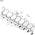
- An egg surface inspection apparatus 1 is an inspection apparatus provided in an egg grading system (not shown) for detecting eggs having a relatively significantly cracked or recessed portion. As shown in Figs. 1 to 3 , the apparatus inspects a surface of an egg E while conveying egg E with its longitudinal axis extending substantially horizontally and also substantially orthogonal to a direction A in which egg E is conveyed (or proceeds).
- Egg surface inspection apparatus 1 includes a conveying unit 2, a light projecting unit 3, an imaging unit 4, and a determination unit 5.
- Conveying unit 2 conveys egg E while rotating egg E with the egg's longitudinal axis serving as a rotation axis.
- Light projecting unit 3 emits linear light extending in a direction substantially orthogonal to conveying direction A of conveying unit 2.
- Imaging unit 4 recognizes egg E irradiated with the linear light by light projecting unit 3 as a two-dimensional image.
- Determination unit 5 determines a state of a surface of egg E based on positional data of the linear light imaged by imaging unit 4.
- "conveying egg E while rotating egg E with the egg's longitudinal axis serving as a rotation axis” also includes conveying egg E while egg E is rotated without its longitudinal axis matching the actual rotation axis of egg E when egg E rotates.
- conveying unit 2 holds egg E by a pair of spool-shaped rollers 21 adjacent to each other in a frontward and rearward direction of conveyance and moves egg E downstream in conveying direction A.
- Conveying unit 2 is mainly composed of a plurality of spool-shaped rollers 21, a roller shaft 22, and a roller regulating unit 23. Eggs E are held by the plurality of spool-shaped roller 21.
- Roller shaft 22 is disposed at a predetermined interval.
- Spool-shaped roller 21 is attached to each roller shaft 22.
- Roller regulating unit 23 is provided at one end of roller shaft 22.
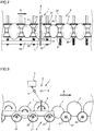
- each spool-shaped roller 21 rotates with roller shaft 22 serving as a rotation axis counterclockwise, as indicated in the figure by an arrow.
- egg E placed on spool-shaped roller 21 rotates clockwise as viewed opposite to the plane of the figure, as indicated in the figure by an arrow.
- spool-shaped roller 21 has a shape in which a vicinity of a center in a widthwise direction is recessed more than opposite ends in the widthwise direction.
- six spool-shaped rollers 21 are fixed to roller shafts 22.
- roller shaft 22 extends in a direction orthogonal to conveying direction A.
- Roller shaft 22 has opposite ends rotatably attached to a chain (not shown).
- a plurality of roller shafts 22 are disposed in parallel.
- roller regulating unit 23 is provided in conveying unit 2 at a predetermined position corresponding to a position where light projecting unit 3 and imaging unit 4 are disposed. Roller regulating unit 23 is disposed in contact with an upper portion of roller shaft 22. Frictional force is generated by roller regulating unit 23 brought into contact with roller shaft 22. Roller regulating unit 23, serving as a rotation imparting unit, applies its frictional force to roll roller shaft 22 and spool-shaped roller 21.
- spool-shaped rollers 21 adjacent to each other in conveying direction A both rotate in the same direction, and egg E held by the adjacent spool-shaped rollers 21 is rotated in a direction opposite to that in which spool-shaped rollers 21 rotate.
- Egg E rolls in a direction to roll in conveying direction A.
- spool-shaped roller 21 has an inclined portion 24 having a diameter larger than that in a vicinity of the center of the roller in the axial direction, and when spool-shaped roller 21 rotates, egg E is positionally adjusted so that egg E has its longitudinal axis substantially parallel to roller shaft 22 and egg E has its thick portion positioned at the center of the convey path.
- Fig. 1 shows a single egg E irradiated with light.
- a single light source may irradiate the plurality of rows of eggs with light.
- Light projecting unit 3 emits light spreading in a two-dimensional sector.
- a point light source and a cylindrical lens or the like are combined together.
- a single line L (a line of light) is formed on conveying unit 2 and a surface of egg E located on conveying unit 2.
- Line L extends in a widthwise direction traversing conveying direction A.
- Line L extending in a straight line is formed substantially parallel to roller shaft 22.
- line L of light emitted to a plane will be a straight line
- line L of light emitted to egg E will be a curved line reflecting an external shape of egg E, as shown in Figs. 1 , 4 and 5 .
- Fig. 4 for an egg E which does not have a significantly cracked or recessed portion, a shape along a smooth shape of egg E appears.
- FIGs. 4 and 5 each show a graph representing in the XY plane (or two dimensionally) positional data of line L of light irradiating egg E.
- the X coordinate corresponds to the widthwise direction traversing conveying direction A. The higher a level from a reference surface of egg E conveyed to an upper portion of egg E exposed to line L of light is, the larger the Y coordinate is.
- imaging unit 4 is a camera provided at a position where a single line L of light projected on egg E can be imaged.
- Imaging unit 4 is disposed obliquely above the conveying device and upstream of light projecting unit 3 in conveying direction A, and fixed to a supporting member (not shown).
- An angle formed by a direction in which light projecting unit 3 emits light toward an egg and a direction toward imaging unit 4 from line L formed on a surface of the egg is set to a predetermined angle.
- positional information of line L (a line of light) can be obtained from information of line L imaged by imaging unit 4. That is, a level of line L at each of different locations from the reference surface of egg E conveyed can be calculated.
- Information of a height of egg E calculated is recognized as information of an external shape (or surface shape) of egg E.
- determination unit 5 determines a state of the surface based on the information of a shape of a line of light of an image captured.
- a state of a surface of the eggshell of egg E imaged is determined depending on whether the positional data obtained from the line of light includes "positional data corresponding to a recessed or projecting portion which would not be calculated for an uncracked/unbroken, and accordingly normal egg.”
- Determination unit 5 (an image processing means) may be anything that can determine a state of a surface of egg E based on a captured image, and is not limited to an embodiment described hereinafter.
- Egg surface inspection apparatus 1 has each component controlled by a control device (not shown), which is a microcomputer system having a processor, a memory, an input interface, an output interface, and the like.
- a control device which is a microcomputer system having a processor, a memory, an input interface, an output interface, and the like.
- Egg E conveyed to detection position 6 is irradiated with light and line L or the like accordingly projected on a surface of egg E is imaged by imaging unit 4 (step S1). Subsequently, data of the captured image is input to determination unit 5 (or the image processing means) (step S2). Determination unit 5 (the image processing means) extracts positional data of line L based on the data of the image (step S3).
- positional data F Whether the extracted positional data corresponds to the positional data for a case where there is a portion recessed downward (or in a negative direction along the Y axis) (positional data F) is determined (step S4).
- positional data F it is determined that egg E inspected has a cracked or recessed portion (step S5).
- it is determined that egg E inspected does not have a cracked or recessed portion (step S6).
- step S4 although depending on the location, size and shape of a cracked or recessed portion in egg E, for example differentiating the positional data to calculate a slope of line L allows a determination to be more easily made.
- step S4 it may be determined whether the extracted positional data corresponds to the positional data for a case where there is a portion projecting upward (or in a positive direction along the Y axis) (positional data G). In that case, it can be determined whether egg E has a surface with a foreign matter adhering thereto.
- a series of steps from imaging to making a determination, or an inspection, is repeated for the entire circumference of egg E by projecting light to different surfaces of egg E successively while rotating egg E. If it is determined while repeatedly performing the process for the entire circumference of egg E that "the egg has a cracked or recessed surface," a subsequent process for that egg E may be cancelled.
- egg surface inspection apparatus 1 operates to inspect a surface of egg E while conveying egg E.
- Egg surface inspection apparatus 1 includes conveying unit 2, light projecting unit 3, imaging unit 4, and determination unit 5.
- Conveying unit 2 conveys egg E while rotating egg E with the egg's longitudinal axis serving as a rotation axis.
- Light projecting unit 3 emits linear light extending in a direction traversing conveying direction A of conveying unit 2.
- Imaging unit 4 recognizes egg E irradiated with the linear light by light projecting unit 3 as a two-dimensional image.
- Determination unit 5 determines a state of a surface of egg E based on positional data of the linear light imaged by imaging unit 4.
- egg surface inspection apparatus 1 described above employs a method referred to as a "light section method" to inspect a surface of an egg.
- the object to be inspected is irradiated with light in a line.
- the irradiated object reflects light and the reflection is obtained as positional data. Based on the obtained positional data of the reflected light, a surface of an egg is inspected.
- egg E When egg E has an eggshell having a relatively significantly cracked, chipped or recessed portion, egg E has an external shape which is significantly different from that of a normal egg. Accordingly, by using a linear light to obtain positional data regarding an external shape (or contour) of an egg, as described above, it can be determined whether the egg has a cracked, chipped, recessed or similarly damaged portion.
- Egg surface inspection apparatus 1 described above processes a captured image of egg E to obtain positional data. In doing so, by determining a state of a surface of egg E based on positional data of linear light imaged, processing the image can be significantly easily done. This eliminates the necessity of performing a process to extract a feature, such as distinguishing an eggshell from background, as done in image-processing performed in a crack inspection apparatus as conventional.
- An inspection of a surface of an egg in the light section method is also advantageous in that the inspection is less easily affected by a change of a gloss of an eggshell of an egg as moisture or the like adheres to the egg, or a difference in eggshell color between a white shell, a pink shell or a brown shell.
- egg surface inspection apparatus 1 comprises conveying unit 2 that conveys egg E while rotating (or rolling) egg E. This allows positional data of a surface of egg E to be obtained for the entire circumference of the egg, and used to determine whether the egg has a cracked or recessed surface.
- egg E will rotate while being conveyed. At the time, egg E rotates (rolls) in a direction to roll in conveying direction A as spool-shaped roller 21 rotates.
- egg surface inspection apparatus 1 comprising a single light projecting unit 3 and a single imaging unit 4 fixed thereto to inspect the entire circumferential surface of egg E.
- a dirty egg inspection apparatus for inspecting dirt on an egg is also provided with a conveying unit which rotates the egg while conveying it.
- the egg is rotated in a direction to roll in a direction opposite to the conveying direction.
- an egg is imaged by an imaging unit disposed at a plurality of locations from an upstream side toward a downstream side in the conveying direction.
- a velocity of a surface portion of an egg irradiated with light and imaged will be a conveying velocity by the conveying unit (a velocity Vc) minus a velocity of a surface portion of the egg in a direction of a tangent to the surface portion as the egg rotates (a velocity Vd), (i.e., velocity Vc - velocity Vd).
- a direction of rotation of spool-shaped roller 21 and a direction of rotation of egg E are opposite to a direction of rotation corresponding thereto in the case of the conventional dirty egg inspection apparatus. More specifically, in conveying unit 2, roller shaft 22 travels in conveying direction A. Spool-shaped roller 21 rotates with roller shaft 22 as a rotation axis in a direction to roll in a direction opposite to conveying direction A. Egg E rotates in a direction to roll in a direction opposite to that in which spool-shaped roller 21 rotates, that is, in conveying direction A.
- a velocity of a surface portion of egg E irradiated with light will be a conveying velocity by conveying unit 2 (velocity Vc) plus a velocity of a surface portion of egg E in a direction of a tangent to the surface portion as egg E rotates (velocity Vd), (i.e., velocity Vc + velocity Vd).
- the egg can have its entire circumference inspected by egg surface inspection apparatus 1 provided with a light projecting unit and an imaging unit at each of a plurality of locations.
- conveying unit 2 of the above-described egg inspecting apparatus is spool-shaped roller 21 fixed to roller shaft 22.
- a pair of adjacent spool-shaped rollers 21 holds egg E.
- a movement of egg E in the direction of the longitudinal axis of egg E i.e., the conveying widthwise direction
- inclined portion 24 of spool-shaped roller 21 located at one axial end thereof and inclined portion 24 of spool-shaped roller 21 located at the other axial end thereof. This can facilitate setting a conveying widthwise direction in imaging egg E by imaging unit 4.
- spool-shaped roller 21 can be rotated (rolled) by bringing roller shaft 22 into contact with roller regulating unit 23 disposed above roller shaft 22.
- roller regulating unit 23 disposed above roller shaft 22.
- spool-shaped roller 21 can be rotated in a desired direction by a simple structure by roller regulating unit 23, and egg E placed on spool-shaped roller 21 can also be rotated.
- the conveying unit is not limited to the above-described conveying unit 2 in so far as the conveying unit can convey an egg while rotating (rolling) the egg with its longitudinal axis in a predetermined direction (a lateral direction). Furthermore, while in the above-described embodiment conveying unit 2 is assumed to be conveying unit 2 arranged in six rows, the number of rows is not limited to 6 rows, and any number of rows, e.g., a single row, may be applied. Further, spool-shaped roller 21 may be replaced with a different, known roller or the like.
- roller regulating unit 23 is not limited to that shown and may be changed variously in so far as it can rotate spool-shaped roller 21 to rotate (roll) an egg.
- roller regulating unit 23 may be a belt conveyor 25 provided under spool-shaped roller 21, as shown in Figs. 7 and 8 .
- Belt conveyor 25 has an upper surface brought into contact with spool-shaped roller 21 to cause frictional force to thus serve as a rotation imparting means for rotating spool-shaped roller 21.
- any member identical to that of egg surface inspection apparatus 1 according to the above-described embodiment is identically denoted and will not be described repeatedly.
- spool-shaped rollers 21 each rotating about roller shaft 22 in a direction to roll in a direction opposite to the conveying direction will allow eggs E placed on spool-shaped rollers 21 to rotate in a direction to roll in the conveying direction.
- belt conveyor 25 is rotated in such a manner that belt conveyor 25 has its upper surface moved in the conveying direction. It suffices that a traveling velocity Vb of belt conveyor 25 is set to be larger than a traveling velocity Va of the conveying unit. In conveying unit 2, belt conveyor 25 will directly rotate the body of spool-shaped roller 21 having a diameter larger than the diameter of roller shaft 22. Accordingly, when an inspection is conducted by using light projecting and imaging units 3 and 4 fixed to the egg surface inspection apparatus, it is necessary to set traveling velocity Vb to be considerably faster than traveling velocity Va.
- the light projecting unit is not limited to the above-described light projecting unit 3 in so far as the light emitted thereby and irradiating an egg can be detected by the imaging unit as a line (a line of light).
- various types of light projecting units are applicable in so far as they are used for a so-called "light section method.”
- the above-described point light source may be substituted with a light projecting unit comprising a laser and a cylindrical lens or the like in combination.
- the light projecting unit is not limited to a light projecting unit which irradiates an egg with a single line of light, and a light projecting unit which emits light forming a plurality of lines is also applicable.
- a light projecting unit which emits light forming a streaky or similar pattern is applicable.
- the determination unit (or a determination method) is not limited to the determination unit according to the above-described embodiment. For example, if it is difficult to distinguish which portion of a surface of an egg in data of a captured image of the egg is exposed to light and which portion thereof is not, the captured image may be binarized and a portion of a surface of the egg that is exposed to light may be extracted.
- the method of detecting a downwardly recessed portion in positional data of a line is not limited to the above-described embodiment.
- an ideal external shape position estimated from each positional data in one image data, that can be assumed for an uncracked or unbroken external shape is calculated.
- this ideal external shape position is compared with a coordinate of actual positional data. If the actual positional data has a Y coordinate having a value smaller than that of the ideal external shape position, it can be determined that there is a downwardly recessed portion at the position of an X coordinate corresponding to that Y coordinate.
- the actual positional data has a Y coordinate having a value (substantially) equal to that of the ideal external shape position, it can be determined that there is no recess or projection at the position of the X coordinate corresponding to that Y coordinate and that an uncracked or unbroken, and hence ideal external shape is had. Furthermore, if the actual positional data has a Y coordinate having a value larger than that of the ideal external shape position, it can be determined that there is an upwardly projecting portion at the position of the X coordinate corresponding to that Y coordinate.
- a downwardly recessed portion may be found from one image data obtained from the egg at one circumferential location and other image data obtained from the egg at another circumferential location.
- a downwardly recessed portion can be found by comparing positional data obtained from one image data with positional data obtained from other image data.
- average positional data of positional data obtained from image data of an uncracked or unbroken, and hence normal egg may be obtained in advance, and positional data obtained from one image data may be compared with the average positional data to find a downwardly recessed portion.
- imaging unit 4 While in the above-described egg surface inspection apparatus, imaging unit 4 is disposed upstream of light projecting unit 3 in the conveying direction, imaging unit 4 may be disposed downstream of light projecting unit 3 in the conveying direction.
- the present invention can be effectively applied to an egg surface inspection apparatus which detects a flaw or deformation of an external shape of an eggshell.
- 1 egg surface inspection apparatus
- 2 conveying unit
- 21 spool-shaped roller
- 22 roller shaft
- 3 light projecting unit
- 4 imaging unit
- 5 determination unit
- E egg.
Landscapes
- Life Sciences & Earth Sciences (AREA)
- Health & Medical Sciences (AREA)
- Chemical & Material Sciences (AREA)
- Physics & Mathematics (AREA)
- General Physics & Mathematics (AREA)
- Analytical Chemistry (AREA)
- Biochemistry (AREA)
- General Health & Medical Sciences (AREA)
- Immunology (AREA)
- Pathology (AREA)
- Engineering & Computer Science (AREA)
- Food Science & Technology (AREA)
- Environmental Sciences (AREA)
- Medicinal Chemistry (AREA)
- Computer Vision & Pattern Recognition (AREA)
- Animal Husbandry (AREA)
- Biodiversity & Conservation Biology (AREA)
- Investigating Materials By The Use Of Optical Means Adapted For Particular Applications (AREA)
- Length Measuring Devices By Optical Means (AREA)
- Rollers For Roller Conveyors For Transfer (AREA)
- Sorting Of Articles (AREA)
Applications Claiming Priority (2)
| Application Number | Priority Date | Filing Date | Title |
|---|---|---|---|
| JP2016027563A JP2017146174A (ja) | 2016-02-17 | 2016-02-17 | 卵の表面検査装置 |
| PCT/JP2017/004750 WO2017141813A1 (fr) | 2016-02-17 | 2017-02-09 | Appareil d'inspection de surface d'œuf |
Publications (1)
| Publication Number | Publication Date |
|---|---|
| EP3399302A1 true EP3399302A1 (fr) | 2018-11-07 |
Family
ID=59625935
Family Applications (1)
| Application Number | Title | Priority Date | Filing Date |
|---|---|---|---|
| EP17753071.4A Withdrawn EP3399302A1 (fr) | 2016-02-17 | 2017-02-09 | Appareil d'inspection de surface d' oeuf |
Country Status (5)
| Country | Link |
|---|---|
| EP (1) | EP3399302A1 (fr) |
| JP (1) | JP2017146174A (fr) |
| KR (1) | KR20170096970A (fr) |
| CN (1) | CN108700528A (fr) |
| WO (1) | WO2017141813A1 (fr) |
Families Citing this family (6)
| Publication number | Priority date | Publication date | Assignee | Title |
|---|---|---|---|---|
| US20220228854A1 (en) * | 2019-06-27 | 2022-07-21 | Otsuka Electronics Co., Ltd. | Measurement device and measurement method |
| CN111136027B (zh) * | 2020-01-14 | 2024-04-12 | 广东技术师范大学 | 一种基于卷积神经网络的咸鸭蛋品质分检装置及方法 |
| JP7377538B2 (ja) * | 2020-05-21 | 2023-11-10 | 株式会社ナベル | 割卵された卵の観測装置 |
| JP7332645B2 (ja) * | 2021-03-17 | 2023-08-23 | 芝浦機械株式会社 | 工具の形状異常検出装置、工具の形状異常検出方法 |
| CN115043009B (zh) * | 2022-06-21 | 2024-01-09 | 寿光市一龙机械制造有限公司 | 一种禽蛋智能视觉分拣包装设备、控制系统及实现方法 |
| JP7389523B1 (ja) * | 2023-01-06 | 2023-11-30 | 株式会社日本選別化工 | 卵表面検査装置 |
Family Cites Families (14)
| Publication number | Priority date | Publication date | Assignee | Title |
|---|---|---|---|---|
| IL68394A0 (en) * | 1982-09-30 | 1983-07-31 | Pennwalt Corp | Fruit sorting apparatus |
| EP0373261A1 (fr) * | 1988-12-14 | 1990-06-20 | Staalkat B.V. | Méthode et appareil pour le contrôle automatique d'oeufs ayant des pailles ou des défauts tels que fêlures, sang, saleté, fuite, une forme aberrante ou similaire |
| NL8901225A (nl) * | 1989-05-17 | 1990-12-17 | Staalkat Bv | Werkwijze en inrichting voor het controleren en verder verwerken van eieren. |
| US5615777A (en) * | 1995-01-17 | 1997-04-01 | Fps Food Processing Systems | Egg candling system |
| JPH0961418A (ja) * | 1995-08-29 | 1997-03-07 | Kyowa Kikai Kk | 卵検査装置 |
| JPH09192611A (ja) * | 1996-01-24 | 1997-07-29 | Techno Ishii:Kk | 画像読取り装置 |
| JP4793770B2 (ja) * | 2001-01-05 | 2011-10-12 | 株式会社ナベル | 卵殻の表面状態検出方法及びこの方法を用いる卵殻の表面状態検出装置 |
| US7173708B2 (en) * | 2003-12-05 | 2007-02-06 | Sunkist Growers Inc. | Method and apparatus for detecting damage in plant products |
| NL1031823C2 (nl) * | 2006-05-16 | 2007-11-20 | Staalkat Internat B V | Detectie van open breuken in eieren. |
| JP5563372B2 (ja) * | 2010-05-20 | 2014-07-30 | 第一実業ビスウィル株式会社 | 外観検査装置 |
| PL2635903T3 (pl) * | 2010-11-05 | 2019-02-28 | Moba Group B.V. | Sposób i urządzenie do badania skorupek jaj |
| JP6178138B2 (ja) * | 2013-07-09 | 2017-08-09 | 池上通信機株式会社 | 3次元形状計測装置 |
| JP2015067363A (ja) * | 2013-09-30 | 2015-04-13 | 株式会社ナベル | 卵の方向特定装置および方向整列装置 |
| JP6188067B2 (ja) * | 2013-09-30 | 2017-08-30 | 株式会社ナベル | 卵の形状推定装置 |
-
2016
- 2016-02-17 JP JP2016027563A patent/JP2017146174A/ja active Pending
-
2017
- 2017-02-09 EP EP17753071.4A patent/EP3399302A1/fr not_active Withdrawn
- 2017-02-09 WO PCT/JP2017/004750 patent/WO2017141813A1/fr active Application Filing
- 2017-02-09 CN CN201780011939.XA patent/CN108700528A/zh active Pending
- 2017-02-17 KR KR1020170021347A patent/KR20170096970A/ko not_active Application Discontinuation
Also Published As
| Publication number | Publication date |
|---|---|
| JP2017146174A (ja) | 2017-08-24 |
| WO2017141813A1 (fr) | 2017-08-24 |
| KR20170096970A (ko) | 2017-08-25 |
| CN108700528A (zh) | 2018-10-23 |
Similar Documents
| Publication | Publication Date | Title |
|---|---|---|
| EP3399302A1 (fr) | Appareil d'inspection de surface d' oeuf | |
| CN107735674B (zh) | 表面缺陷检测装置、表面缺陷检测方法及钢材的制造方法 | |
| KR101832081B1 (ko) | 표면 결함 검출 방법 및 표면 결함 검출 장치 | |
| JP5388250B2 (ja) | フィルタ検査方法および装置 | |
| JP6394514B2 (ja) | 表面欠陥検出方法、表面欠陥検出装置、及び鋼材の製造方法 | |
| CN107709977B (zh) | 表面缺陷检测装置及表面缺陷检测方法 | |
| JP4739044B2 (ja) | 外観検査装置 | |
| WO2016208626A1 (fr) | Procédé et dispositif de détection de défauts superficiels, et procédé de fabrication pour un matériau d'acier | |
| WO2020110667A1 (fr) | Procédé et dispositif de détection de défauts de surface, procédé et équipement de fabrication de matériau en acier, procédé de contrôle de qualité de matériau en acier, procédé de création de modèle de détermination de défauts de surface et modèle de détermination de défauts de surface | |
| JP2009293999A (ja) | 木材欠陥検出装置 | |
| US20120105624A1 (en) | Method and device for defect inspection in separated transparent and/or semi-transparent body | |
| JP5732605B2 (ja) | 外観検査装置 | |
| JP6007639B2 (ja) | 疵検出方法および疵検出装置 | |
| JP3909457B2 (ja) | 銅箔表面検査装置、および銅箔表面検査方法 | |
| JP6387909B2 (ja) | 表面欠陥検出方法、表面欠陥検出装置、及び鋼材の製造方法 | |
| JP2010002232A (ja) | 鍛造品の検査方法 | |
| JP4016381B2 (ja) | 表面欠陥検査装置 | |
| JP5297245B2 (ja) | 物体表面検査装置 | |
| JP2018179563A (ja) | 表面検査装置および表面検査方法 | |
| JP2000275033A (ja) | 表面欠陥検査装置 | |
| JP6409606B2 (ja) | キズ欠点検査装置およびキズ欠点検査方法 | |
| JP2009047517A (ja) | 検査装置 | |
| JP2001317927A (ja) | スリット形状溝検査装置および方法 | |
| WO2011101893A1 (fr) | Procédé et dispositif pour détecter un défaut sur une surface d'un objet souple devant être testé | |
| JP7131509B2 (ja) | 表面欠陥検出装置、表面欠陥検出方法、及び鋼材の製造方法 |
Legal Events
| Date | Code | Title | Description |
|---|---|---|---|
| STAA | Information on the status of an ep patent application or granted ep patent |
Free format text: STATUS: THE INTERNATIONAL PUBLICATION HAS BEEN MADE |
|
| PUAI | Public reference made under article 153(3) epc to a published international application that has entered the european phase |
Free format text: ORIGINAL CODE: 0009012 |
|
| STAA | Information on the status of an ep patent application or granted ep patent |
Free format text: STATUS: REQUEST FOR EXAMINATION WAS MADE |
|
| 17P | Request for examination filed |
Effective date: 20180730 |
|
| AK | Designated contracting states |
Kind code of ref document: A1 Designated state(s): AL AT BE BG CH CY CZ DE DK EE ES FI FR GB GR HR HU IE IS IT LI LT LU LV MC MK MT NL NO PL PT RO RS SE SI SK SM TR |
|
| AX | Request for extension of the european patent |
Extension state: BA ME |
|
| STAA | Information on the status of an ep patent application or granted ep patent |
Free format text: STATUS: THE APPLICATION HAS BEEN WITHDRAWN |
|
| 18W | Application withdrawn |
Effective date: 20190103 |