EP3398745B1 - Schneidlastfreigabevorrichtung für schneidausrüstung - Google Patents
Schneidlastfreigabevorrichtung für schneidausrüstung Download PDFInfo
- Publication number
- EP3398745B1 EP3398745B1 EP16882959.6A EP16882959A EP3398745B1 EP 3398745 B1 EP3398745 B1 EP 3398745B1 EP 16882959 A EP16882959 A EP 16882959A EP 3398745 B1 EP3398745 B1 EP 3398745B1
- Authority
- EP
- European Patent Office
- Prior art keywords
- rotating arm
- arm
- supporting
- cutting
- supporting arm
- Prior art date
- Legal status (The legal status is an assumption and is not a legal conclusion. Google has not performed a legal analysis and makes no representation as to the accuracy of the status listed.)
- Not-in-force
Links
Images


Classifications
-
- B—PERFORMING OPERATIONS; TRANSPORTING
- B23—MACHINE TOOLS; METAL-WORKING NOT OTHERWISE PROVIDED FOR
- B23D—PLANING; SLOTTING; SHEARING; BROACHING; SAWING; FILING; SCRAPING; LIKE OPERATIONS FOR WORKING METAL BY REMOVING MATERIAL, NOT OTHERWISE PROVIDED FOR
- B23D57/00—Sawing machines or sawing devices not covered by one of the preceding groups B23D45/00 - B23D55/00
- B23D57/003—Sawing machines or sawing devices working with saw wires, characterised only by constructional features of particular parts
- B23D57/0069—Sawing machines or sawing devices working with saw wires, characterised only by constructional features of particular parts of devices for tensioning saw wires
-
- B—PERFORMING OPERATIONS; TRANSPORTING
- B23—MACHINE TOOLS; METAL-WORKING NOT OTHERWISE PROVIDED FOR
- B23D—PLANING; SLOTTING; SHEARING; BROACHING; SAWING; FILING; SCRAPING; LIKE OPERATIONS FOR WORKING METAL BY REMOVING MATERIAL, NOT OTHERWISE PROVIDED FOR
- B23D57/00—Sawing machines or sawing devices not covered by one of the preceding groups B23D45/00 - B23D55/00
- B23D57/003—Sawing machines or sawing devices working with saw wires, characterised only by constructional features of particular parts
- B23D57/0053—Sawing machines or sawing devices working with saw wires, characterised only by constructional features of particular parts of drives for saw wires; of wheel mountings; of wheels
Definitions
- the present invention relates to the field of cutting equipment technology, and more particularly, to a cutting load release device for a cutting equipment according to the preamble of claim 1.
- a cut part may sink down due to a weight thereof, for example, when a common concrete support beam is being cut and removed, a concrete been cut may sink and form a falling object, generating a pretty large gravity thereof, in tons or even tens of tons, thus, according to that, the falling object is able to drive a diamond beaded rope together with the machine sink for a few centimeters or over a dozen centimeters, and this may cause the diamond beaded rope to be broken, followed by a plurality of injuries or damages, or this may cause the machine damaged with a plurality of frequent failures, and greatly reduce a service life of the machine.
- the purpose of the present invention is overcoming a plurality of defects in the prior art and providing a cutting load release device for a cutting equipment, in order to solve a plurality of problems in the prior art that, due to the cutting equipment adopting a method of breaking some of a plurality of parts to preserve a main part of a machine and secure a cutting tool when a cutting object falls off, and that causes the cutting equipment a plurality of problems, including a discontinuous working period, a trouble-some and time-costing maintenance, a low working efficiency, and a high production cost.
- the present invention is thus realized by a cutting load release device for the cutting equipment, comprising
- the load release recovery component is an extension spring.
- one end of the extension spring connects to the first supporting arm, while another end of the extension spring is connected to the rotating arm, and close to the cutting tool arranged on the rotating arm, while a centerline of the extension spring overlaps a centerline of the rotating arm when the rotating arm locates in the initial region.
- the supporting frame further comprises a second supporting arm, the second supporting arm is arranged above the first supporting arm; one end of the extension spring connects to the second supporting arm, and another end of the extension spring is connected to the rotating arm, close to the cutting tool arranged on the rotating arm, while the centerline of the extension spring has an angle ⁇ away from the centerline of the rotating arm when the rotating arm locates in the initial region, and 0° ⁇ ⁇ ⁇ 90°.
- the supporting frame further comprises the second supporting arm and a third supporting arm, the third supporting arm is located above and arranged opposite to the rotating arm, and the third supporting arm is arranged in parallel to the rotating arm when the rotating arm locates in the initial region, one end of the second supporting arm connects to the first supporting arm, while another end of the second supporting arm connects to the third supporting arm; one end of the extension spring connects to the third supporting arm, another end of the extension spring is connected to the rotating arm, and close to the cutting tool arranged on the rotating arm, while the centerline of the extension spring is perpendicularly intersecting to the centerline of the rotating arm when the rotating arm locates in the initial region.
- the load release recovery component is a compression spring.
- the supporting frame comprises the second supporting arm and the third supporting arm, the third supporting arm is located below and arranged opposite to the rotating arm, and the third supporting arm is arranged in parallel to the rotating arm when the rotating arm locates in the initial region, one end of the second supporting arm connects to the first supporting arm, while another end of the second supporting arm connects to the third supporting arm; one end of the compression spring connects to the third supporting arm, another end of the compression spring is connected to the rotating arm, and close to the cutting tool arranged on the rotating arm, while the centerline of the compression spring is perpendicularly intersecting to the centerline of the rotating arm when the rotating arm locates in the initial region.
- the cutting load release device further comprises a fixation mechanism, applied to locking and fixing the rotating arm, in order to fix the rotating arm at any one position between the initial region and the rotation region.
- the fixation mechanism comprises a locking screw; one end of the locking screw connects to the rotating arm, while another end thereof connects to the first supporting arm.
- the fixation mechanism comprises a vibration damping pad, and a holder applied to holding and positioning the vibration damping pad, the holder connects fixedly to the supporting frame, and the holder has an accommodation groove arranged, applied to accommodating the vibration damping pad, the accommodation groove accommodates a connection part between the rotating arm and the first supporting arm; the vibration damping pad is arranged in the accommodation groove, and touches both of the rotating arm and the first supporting arm.
- a technical effect of the cutting load release device for cutting equipment is: when the cutting tool cuts the cutting object specified, if a part being cut appears to be falling, an action force generated by the part being cut during falling will act directly onto the cutting tool; the cutting tool will transfer a force to the rotating arm after being stressed; the rotating arm will drive the load release recovery component rotate to the rotation region from the initial region after being stressed, and rotate to a corresponding position in the rotation region according to a size of the action force applied hereto, so as to prevent the cutting tool from being crushed by the falling object, attenuate and release the action force that the rotating arm is stressed, by the load release recovery component; when the action force on the rotating arm is attenuated to a certain extent, if a force value of the action force is less than that of a restoring force of the load release recovery component, the load release recovery component will drive the rotating arm return slowly to the initial region from the rotation region, according to an attenuation of the action force on the rotating arm.
- the cutting tool when the cutting tool is cutting the cutting object specified, if a certain part of the cutting object makes a cutting resistance acted on the cutting tool increase in a sudden, due to a plurality of factors including a difference in a dense or a material, the cutting tool will transfer the action force stressed thereof to the rotating arm; after being stressed, the rotating arm will drive the load release recovery component rotate to the rotation region from the initial region, and rotate to the corresponding position in the rotation region according to the size of the action force applied hereto, so as to prevent the cutting tool from being damaged by the resistance increased in a sudden, attenuate and release the action force that the rotating arm is stressed, by the load release recovery component; when the action force on the rotating arm is attenuated to a certain extent, if the force value of the action force is less than that of the restoring force of the load release recovery component, the load release recovery component will drive the rotating arm return slowly to the initial region from the rotation region, according to an attenuation of the action force on the rotating arm.
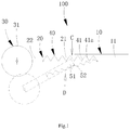
- a cutting load release device 100 comprises a supporting frame 10, a rotating arm 20, a cutting tool 30 and a load release mechanism 40, more descriptions on each of a plurality of parts in the cutting load release device for cutting equipment are stated below:
- the cutting tool 30 when the cutting tool 30 is cutting the cutting object specified, if a certain part of the cutting object makes a cutting resistance acted on the cutting tool 30 increase in a sudden, due to a plurality of factors including a difference in a dense or a material (for example, an uneven material in a marble block), the cutting tool 30 will transfer the action force stressed thereof to the rotating arm 20; after being stressed, the rotating arm 20 will drive the load release recovery component 41 rotate to the rotation region D from the initial region C, and rotate to a corresponding position in the rotation region D, according to a size of the action force applied hereto, so as to prevent the cutting tool 30 from being damaged by the resistance increased in a sudden, attenuate and release the action force that the rotating arm 20 is stressed, by the load release recovery component 41; when the action force on the rotating arm 20 is attenuated to a certain extent, if the force value of the action force is less than that of the restoring force of the load release recovery component 41, the load release recovery component 41 will drive the rotating arm 20 return slowly
- the cutting load release device 100 for cutting equipment described in the present embodiment has a plurality of advantages listed below:
- the load release recovery component 41 is an extension spring 41a, wherein, the extension spring 41a is also called a en extension spring or tension spring, which is a coil spring that takes an axial tension.
- the extension spring 41a is generally made by a material with a round cross-section, of course, the extension spring 41a may also be made by a material with other shaped cross-section including a rectangular cross-section. When there is no load applied, two coils in the extension spring 41a are usually close to each other without any gaps.
- the extension spring 41a when the rotating arm 20 is locating in the initial region C, the extension spring 41a is contracted to close; when the rotating arm 20 turns to the rotation region D, the extension spring 41a may stretch and extend according to a size of the action force transmitted from the rotating arm 20.
- the extension spring 41a is convenient to both manufacturing and installation.
- the extension spring 41a is stretched and extended following a rotation of the rotating arm 20, that buffers and attenuates the action force transmitted after the rotating arm 20 is pressed, so as to achieve an aim of load releasing to the cutting tool 30; when the action force on the rotating arm 20 is attenuated to a certain extent, if a force value of the action force is less than that of a restoring force of the extension spring 41a, the extension spring 41a will drive the rotating arm 20 return slowly to the initial region C from the rotation region D, according to an attenuation of the action force on the rotating arm 20, while the extension spring 41a will also retract to close following the rotating arm 20 returning to the initial region C from the rotation region D.
- one end of the extension spring 41a connects to the first supporting arm 11, while another end of the extension spring 41a is connected to the rotating arm 20, and close to the cutting tool 30 arranged on the rotating arm 20, while a centerline of the extension spring 41a overlaps a centerline of the rotating arm 20 when the rotating arm 20 locates in the initial region C, that means, an angle between the centerline of the extension spring 41a and the centerline of the rotating arm 20 locating in the initial region C is 0°.
- the first end 21 of the rotating arm 20 in the present embodiment has a first rotation portion 51 arranged, and the first supporting arm 11 has a second rotation portion 52 arranged, which fits the first rotation portion 51 in rotation, the first end 21 of the rotating arm 20 fits the second rotation portion 52 in rotation through the first rotation portion 51 before being arranged on the first supporting arm 11 in rotation, wherein, by arranging the first rotation portion 51 and the second rotation portion 52, it achieves a setting in rotation between the first end 21 of the rotating arm 20 and the first supporting arm 11 simply and affectively.
- the first rotation portion 51 is arranged on a bottom end of the first end 21 of the rotating arm 20
- the second rotation portion 52 is arranged on a bottom end of the first supporting arm 11, while the first rotation portion 51 and the second rotation portion 52 connect in a combined way, forming a hinge.
- first rotation portion 51 and the second rotation portion 52 are not limited thereto, it is also possible to set the first rotation portion 51 to be a bearing or a plug shaft, while the second rotation portion 52 is set accordingly to be a plug shaft or a bearing.
- a fitting in rotation between the plug shaft and the bearing not only better achieves the fitting in rotation between the first end 21 of the rotating arm 20 and the first supporting arm 11, but also facilitates the manufacturing and installation.
- a working principle of the cutting load release device 100 for the cutting equipment is further described below, referencing to the attached drawings:
- the cutting tool 30 When the cutting tool 30 is cutting the cutting object specified, if a part being cut appears to be falling, an action force generated by the part being cut during falling will act directly onto the cutting tool 30; the cutting tool 30 will transfer a force to the rotating arm 20 after being stressed; the rotating arm 20 will drive the load release recovery component 41 rotate to the rotation region D from the initial region C after being stressed, and rotate to a corresponding position in the rotation region D according to a size of the action force applied hereto, so as to prevent the cutting tool 30 from being crushed by the falling object, attenuate and release the action force that the rotating arm 20 is stressed, by the load release recovery component 41; when the action force on the rotating arm 20 is attenuated to a certain extent, if a force value of the action force is less that a restoring force of the load release recovery component 41, the load release recovery component 41 will drive the rotating arm 20 return slowly to the initial region C from
- the cutting tool 30 when the cutting tool 30 is cutting the cutting object specified, if a certain part of the cutting object makes a cutting resistance acted on the cutting tool 30 increase in a sudden, due to a plurality of factors including a difference in a dense or a material (for example, an uneven material in a marble block), the cutting tool 30 will transfer the action force stressed thereof to the rotating arm 20; after being stressed, the rotating arm 20 will drive the load release recovery component 41 rotate to the rotation region D from the initial region C, and rotate to a corresponding position in the rotation region D according to a size of the action force applied hereto, so as to prevent the cutting tool from being damaged by the resistance increased in a sudden, attenuate and release the action force that the rotating arm 20 is stressed, by the load release recovery component 41; when the action force on the rotating arm 20 is attenuated to a certain extent, if the force value of the action force is less that the restoring force of the load release recovery component 41, the load release recovery component 41 will drive the rotating arm 20 return slowly to the initial region
- an implementation of the embodiment II is similar to that of the embodiment I, detailed descriptions may be referencing to that of the embodiment I, and will not be stated in details herein. However, a difference in between is:
- one end of the extension spring 41a connects to the first supporting arm 11, while another end of the extension spring 41a is connected to the rotating arm 20, and close to the cutting tool 30 arranged on the rotating arm 20, while a centerline of the extension spring 41a overlaps a centerline of the rotating arm 20 when the rotating arm 20 locates in the initial region C.
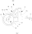
- the supporting frame 10 further comprises a second supporting arm 12a, the second supporting arm 12a is arranged above the first supporting arm 11;
- one end of the extension spring 41a connects to the second supporting arm 12a, and another end of the extension spring 41a is connected to the rotating arm 20, close to the cutting tool 30 arranged on the rotating arm 20, so as to ensure that the extension spring 41a is able to receive the action force transmitted from the rotating arm 20 fast, without affecting the cutting tool 30, which facilitates a purpose of load release for the cutting tool 30; while the centerline of the extension spring 41a has an angle ⁇ away from the centerline of the rotating arm 20 when the rotating arm 20 locates in the initial region C, and 0° ⁇ ⁇ ⁇ 90°.
- the angle is set as 45°, in order to make the extension spring 41a generate an elastic cushion force better, and ensure the load release for the cutting tool 30.
- an implementation of the embodiment III is similar to that of the embodiment II, detailed descriptions may be referencing to that of the embodiment II, and will not be stated in details herein. However, a difference in between is:
- the supporting frame 10 further comprises the second supporting arm 12a, the second supporting arm 12a is arranged above the first supporting arm 11; one end of the extension spring 41a connects to the second supporting arm 12a, and another end of the extension spring 41a is connected to the rotating arm 20, close to the cutting tool 30 arranged on the rotating arm 20, while the centerline of the extension spring 41a has an angle ⁇ away from the centerline of the rotating arm 20 when the rotating arm 20 locates in the initial region C, and 0° ⁇ ⁇ ⁇ 90°.
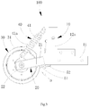
- the supporting frame 10 further comprises a second supporting arm 12b and a third supporting arm 13b, wherein, it should be noted that, the second supporting arm 12b in the embodiment III, although having a same name, position arranged same to the second supporting arm 12a in the embodiment II, they make a different function; the third supporting arm 13b is located above and arranged opposite to the rotating arm 20, and the third supporting arm 13b is arranged in parallel to the rotating arm 20 when the rotating arm 20 locates in the initial region C, one end of the second supporting arm 12b connects to the first supporting arm 11 in perpendicular, while another end of the second supporting arm 12b connects to the third supporting arm 13b; one end of the extension spring 41a connects to the third supporting arm 13b, another end of the extension spring 41a is connected to the rotating arm 20, and close to the cutting tool 30 arranged on the rotating arm 20, so as to ensure that the extension spring 41a is able to receive the action force transmitted from the rotating arm 20 fast, without affecting the cutting tool 30, which facilitates a purpose of load
- the centerline of the extension spring 41a is perpendicularly intersecting to the centerline of the rotating arm 20 when the rotating arm 20 locates in the initial region C, when the action force on the rotating arm 20 is buffered and attenuated to a certain extent, if the force value of the action force is less than that of the restoring force of the extension spring 41a, comparing to a plurality of other settings of the extension spring 41a, a resistance that the extension spring 41a suffers when making an elastic recovery is smaller, that may drive the rotating arm 20 to return to the initial region C from the rotation region D faster, ensuring the cutting tool 30 returning to a position of normal working faster.
- an implementation of the embodiment IV is similar to that of the embodiment III, detailed descriptions may be referencing to that of the embodiment III, and will not be stated in details herein. However, a difference in between is:
- the load release recovery component 41 is the extension spring 41a.
- the supporting frame 10 further comprises the second supporting arm 12b and the third supporting arm 13b, the third supporting arm 13b is located above and arranged opposite to the rotating arm 20, and the third supporting arm 13b is arranged in parallel to the rotating arm 20 when the rotating arm 20 locates in the initial region C, one end of the second supporting arm 12b connects to the first supporting arm 11 in perpendicular, while another end of the second supporting arm 12b connects to the third supporting arm 13b; one end of the extension spring 41a connects to the third supporting arm 13b, another end of the extension spring 41a is connected to the rotating arm 20, and close to the cutting tool 30 arranged on the rotating arm 20, while the centerline of the extension spring 41a is perpendicularly intersecting to the centerline of the rotating arm 20 when the rotating arm 20 locates in the initial region C.
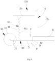
- the load release recovery component 41 is a compression spring 41b.
- the compression spring 41b is a coil spring that takes an axial compression, due to taking a compression, both ends of the compression spring 41b may be open or closed or flattened or smoothed, a cross-section of a material thereof is mainly a circle, or a rectangular or a multi-strand steel, and the compression spring 41b may have an equal pitch or a variable pitch.
- a shape of the compression spring 41b may be a cylinder, a cone, may be convex or concave at a center, may even be a non-circle or a plurality of various variants of a tail end. Coils in the compression spring 41b have a certain gap, and the compression spring 41b shrinks and deforms, when subjected to an extension load, that stores storage deformation energy.
- the supporting frame 10 further comprises a second supporting arm 12c and a third supporting arm 13c, wherein, it should be noted that, the second supporting arm 12c and the third supporting arm 13c in the embodiment IV, although having a name same to the second supporting arm 12b and the third supporting arm 13b in the embodiment III, they have a different position and make a different function; the third supporting arm 13c is located below and arranged opposite to the rotating arm 20, and the third supporting arm 13c is arranged in parallel to the rotating arm 20 when the rotating arm 20 locates in the initial region C, one end of the second supporting arm 12c connects to the first supporting arm 11 in perpendicular, while another end of the second supporting arm 12c connects to the third supporting arm 13c in perpendicular; one end of the compression spring 41b connects to the third supporting arm 13c, another end of the compression spring 41b is connected to the rotating arm 20 which is close to the cutting tool 30, so as to ensure that the compression spring 41b is able to receive the action force transmitted from the rotating arm 20 fast, without affecting the
- the rotating arm 20 When the cutting tool 30 is subjected to a compression, the rotating arm 20 will take the cutting tool 30 rotate downwards, and compress the compression spring 41b, the compression spring 41b will make a corresponding shrink and close according to the size of the action force subjected hereof, while buffering and attenuating the action force transmitted from the rotating arm 20, so as to achieve the purpose of load releasing for the cutting tool 30; when the action force on the rotating arm 20 is buffered and attenuated to a certain extent, if the force value of the action force is less than that of the restoring force of the compression spring 41b, the compression spring 41b will drive the rotating arm 20 return slowly to the initial region C from the rotation region D, according to an attenuation of the action force on the rotating arm 20, while being stretched and extended following the rotating arm 20 returning to the initial region C from the rotation region D.
- the cutting load release device 100 further comprises a fixation mechanism 50, applied to locking and fixing the rotating arm 20, in order to fix the rotating arm 20 at any one position between the initial region C and the rotation region D.
- the fixation mechanism 50 Through a setting of the fixation mechanism 50, it is possible to fix the rotating arm 20 to any one position between the initial region C and the rotation region D, thus making the rotating arm 20 from arranging rotatablly on the first supporting arm 11 and being able to be adjusted freely, to arranging fixedly on the first supporting arm 11. Therefore, in a case of taking an processing efficiency of the cutting device as a first priority, it is possible to fix the rotating arm 20 in the initial region C by the fixation mechanism 50, and the cutting tool 30 will also be fixed following a fixation of the rotating arm 20, that makes the cutting tool 30 locating in the initial region C have a best cutting efficiency, and it is possible to adjust the cutting device in a whole to be one having a high processing efficiency;
- the fixation mechanism 50 in the present embodiment comprises a locking screw (not shown in the figures), one end of the locking screw connects to the rotating arm 20, another end connects to the first supporting arm 11.
- a locking screw (not shown in the figures)
- one end of the locking screw connects to the rotating arm 20, another end connects to the first supporting arm 11.
- An arrangement of the locking screw is easy to install, with a simple structure.
- the fixation mechanism 50 comprises a locking screw, and one end of the locking screw connects to the rotating arm 20, while another end connects to the first supporting arm 11.
- the fixation mechanism 50 comprises a vibration damping pad 51, and a holder 52 applied to holding and positioning the vibration damping pad 51, the holder 52 connects fixedly to the supporting frame 10, and the holder 52 has an accommodation groove 521 arranged, applied to accommodating the vibration damping pad 51, the accommodation groove 521 accommodates a connection part between the rotating arm 20 and the first supporting arm 11; the vibration damping pad 51 is arranged in the accommodation groove 521, and touches both of the rotating arm 20 and the first supporting arm 11.
- the vibration damping pad 51 it is possible to set a different hardness according to any actual requirements. If it is needed for the vibration damping pad 51 to totally resist both of the rotating arm 20 and the first supporting arm 11, so as to fix the rotating arm 20 in the initial region C, it is possible to select a vibration damping pad 51 with a Shore hardness of 70-100 HA, and most of the cases like this are taking the processing efficiency of the cutting device as a first priority; if it is needed that the vibration damping pad 51 makes an action of buffering and damping to the rotating arm 20, it is possible to select a vibration damping pad 51 with a Shore hardness of 30-60 HA. Also, it may be seen that, the setting of the vibration damping pad 51 may be flexibly set according to an actual situation and a customer need.
- the vibration damping pad 51 may be made of a rubber material, or other plastic materials, or other soft vibration damping materials.
Landscapes
- Engineering & Computer Science (AREA)
- Mechanical Engineering (AREA)
- Sawing (AREA)
Claims (10)
- Schneidlastfreigabevorrichtung für eine Schneidausrüstung, umfassend:einen Tragrahmen (10), der zur Montage einer Vielzahl von Bauteilen und zum Tragen der Bauteile dient, wobei der Tragrahmen (10) einen ersten Tragarm (11) umfasst;einen Dreharm (20), der dazu dient, eine Vielzahl von Bauteilen daran durch Drehung zu bewegen, und der dafür sorgt, dass sich die Bauteile in eine andere Position bewegen können, wenn Druck auf die Bauteile ausgeübt wird, wobei der Dreharm (20) ein erstes Ende (21) und ein entgegengesetzt zu dem ersten Ende (21) angeordnetes zweites Ende (22) umfasst, das erste Ende (21) des Dreharms (20) drehbar an dem ersten Tragarm (11) angeordnet ist, während zwischen dem Dreharm (20) und dem ersten Tragarm (11) ein Drehbereich (D) angeordnet ist, der den Dreharm (20) relativ zu dem ersten Tragarm (11) drehbar macht;ein Schneidwerkzeug (30), das ein Arbeitsrad (31) und ein auf das Arbeitsrad (31) gewickelten Diamantperlenseil, das zum Schneiden eines Schneidobjekts eingesetzt wird, umfasst, wobei das Schneidwerkzeug (30) drehbar an dem zweiten Ende (22) des Dreharms (20) angeordnet ist; undeinen Lastfreigabemechanismus (40), der zum Durchführen eines Entlastungsvorgangs bei einer abnormal großen Last, die durch das Schneidwerkzeug (30) aufgebracht wird, aufgrund eines abnormalen Zustands angewendet wird, wobei der Lastfreigabemechanismus (40) eine Lastfreigabe-Wiederherstellungskomponente (41) umfasst, die die abnormal große Last, die durch das Schneidwerkzeug (30) aufgebracht wird, entlasten kann, wobei ein Ende der Lastfreigabe-Wiederherstellungskomponente (41) mit dem Tragrahmen (10) verbunden ist, während ein anderes Ende der Lastfreigabe-Wiederherstellungskomponente (41) mit dem Dreharm (20) verbunden ist,dadurch gekennzeichnet, dasszwischen dem Dreharm (20) und dem ersten Tragarm (11) weiterhin ein Anfangsbereich (C) vorhanden ist, der dafür sorgt, dass der Dreharm (20) relativ zu dem ersten Tragarm (11) stationär ist, unddie Lastfreigabe-Wiederherstellungskomponente (41) auch den Dreharm (20) antreiben kann, um aus dem Drehbereich (D) in den Anfangsbereich (C) zurückzukehren.
- Schneidlastfreigabevorrichtung nach Anspruch 1, wobei die Lastfreigabe-Wiederherstellungskomponente (41) eine Zugfeder (41a) ist.
- Schneidlastfreigabevorrichtung nach Anspruch 2, wobei ein Ende der Zugfeder (41a) mit dem ersten Tragarm (11) verbunden ist, während ein anderes Ende der Zugfeder (41a) mit dem Dreharm (20) nahe bei dem an dem Dreharm (20) angeordneten Schneidwerkzeugs (30) verbunden ist, während eine Mittellinie der Zugfeder (41a) eine Mittellinie des Dreharms (20) überlappt, wenn sich der Dreharm (20) in dem Anfangsbereich (C) befindet.
- Schneidlastfreigabevorrichtung nach Anspruch 2, wobei der Tragrahmen (10) ferner einen zweiten Tragarm (12a) umfasst, wobei der zweite Tragarm (12a) oberhalb des ersten Tragarms (11) angeordnet ist;
ein Ende der Zugfeder (41a) mit dem zweiten Tragarm (12a) verbunden ist, und ein anderes Ende der Zugfeder (41a) mit dem Dreharm (20) nahe bei dem Schneidwerkzeug (30), das auf dem Dreharm (20) angeordnet ist, verbunden ist, während die Mittellinie der Zugfeder (41a) einen Winkel θ von der Mittellinie des Dreharms (20) entfernt aufweist, wenn der Dreharm (20) sich in dem Anfangsbereich (C) befindet, und 0° < θ < 90°. - Schneidlastfreigabevorrichtung nach Anspruch 2, wobei der Tragrahmen (10) ferner den zweiten Tragarm (12b) und einen dritten Tragarm (13b) umfasst, der dritte Tragarm (13b) sich oberhalb des Dreharms (20) befindet und diesem gegenüber angeordnet ist, und der dritte Tragarm (13b) parallel zu dem Dreharm (20) angeordnet ist, wenn sich der Dreharm (20) in dem Anfangsbereich (C) befindet, wobei ein Ende des zweiten Tragarms (12b) mit dem ersten Tragarm (11) verbunden ist, während ein anderes Ende des zweiten Tragarms (12b) mit dem dritten Tragarm (13b) verbunden ist;
ein Ende der Zugfeder (41a) mit dem dritten Tragarm (13b) verbunden ist, ein anderes Ende der Zugfeder (41a) mit dem Dreharm (20) nahe bei dem an dem Dreharm (20) angeordneten Schneidwerkzeug (30) verbunden ist, während die Mittellinie der Zugfeder (41a) die Mittellinie des Dreharms (20) senkrecht schneidet, wenn sich der Dreharm (20) in dem Anfangsbereich (C) befindet. - Schneidlastfreigabevorrichtung nach Anspruch 1, wobei die Lastfreigabe-Wiederherstellungskomponente (41) eine Druckfeder (41b) ist.
- Schneidlastfreigabevorrichtung nach Anspruch 6, wobei der Tragrahmen (10) den zweiten Tragarm (12c) und den dritten Tragarm (13c) umfasst, der dritte Tragarm (13c) sich unterhalb des Dreharms (20) befindet und diesem gegenüber angeordnet ist, und der dritte Tragarm (13c) parallel zu dem Dreharm (20) angeordnet ist, wenn sich der Dreharm (20) in dem Anfangsbereich (C) befindet, ein Ende des zweiten Tragarms (12c) mit dem ersten Tragarm (11) verbunden ist, während ein anderes Ende des zweiten Tragarms (12c) mit dem dritten Tragarm (13c) verbunden ist;
ein Ende der Druckfeder (41b) mit dem dritten Tragarm (13c) verbunden ist, ein anderes Ende der Druckfeder (41b) mit dem Dreharm (20) nahe bei dem an dem Dreharm (20) angeordneten Schneidwerkzeug (30) verbunden ist, während die Mittellinie der Druckfeder (41b) die Mittellinie des Dreharms (20) senkrecht schneidet, wenn sich der Dreharm (20) in dem Anfangsbereich (C) befindet. - Schneidlastfreigabevorrichtung nach einem der Ansprüche 1-7, wobei die Schneidlastfreigabevorrichtung (100) ferner einen Befestigungsmechanismus (50) umfasst, der zum Verriegeln und Befestigen des Dreharms (20) eingesetzt wird, um den Dreharm (20) in einer beliebigen Position zwischen dem Anfangsbereich (C) und dem Drehbereich (D) zu fixieren.
- Schneidlastfreigabevorrichtung nach Anspruch 8, wobei der Befestigungsmechanismus (50) eine Feststellschraube umfasst, wobei ein Ende der Feststellschraube mit dem Dreharm (20) verbunden ist, während ihr anderes Ende mit dem ersten Tragarm (11) verbunden ist.
- Schneidlastfreigabevorrichtung nach Anspruch 8, wobei der Befestigungsmechanismus (50) ein schwingungsdämpfendes Kissen (51) und einen Halter (52) umfasst, der zum Halten und Positionieren des schwingungsdämpfenden Kissens (51) angebracht ist, der Halter (52) fest mit dem Tragrahmen (10) verbunden ist und der Halter (52) eine Aufnahmenut (521) aufweist, die zur Aufnahme des schwingungsdämpfenden Kissens (51) angebracht ist, die Aufnahmenut (521) einen Verbindungsteil zwischen dem Dreharm (20) und dem ersten Tragarm (11) aufnimmt; und das schwingungsdämpfende Kissen (51) in der Aufnahmenut (521) angeordnet ist und sowohl den Dreharm (20) als auch den ersten Tragarm berührt.
Applications Claiming Priority (1)
| Application Number | Priority Date | Filing Date | Title |
|---|---|---|---|
| PCT/CN2016/070518 WO2017117814A1 (zh) | 2016-01-08 | 2016-01-08 | 切割设备的切割卸荷装置 |
Publications (3)
| Publication Number | Publication Date |
|---|---|
| EP3398745A1 EP3398745A1 (de) | 2018-11-07 |
| EP3398745A4 EP3398745A4 (de) | 2019-08-28 |
| EP3398745B1 true EP3398745B1 (de) | 2021-09-08 |
Family
ID=59273163
Family Applications (1)
| Application Number | Title | Priority Date | Filing Date |
|---|---|---|---|
| EP16882959.6A Not-in-force EP3398745B1 (de) | 2016-01-08 | 2016-01-08 | Schneidlastfreigabevorrichtung für schneidausrüstung |
Country Status (2)
| Country | Link |
|---|---|
| EP (1) | EP3398745B1 (de) |
| WO (1) | WO2017117814A1 (de) |
Family Cites Families (11)
| Publication number | Priority date | Publication date | Assignee | Title |
|---|---|---|---|---|
| JPH0970746A (ja) * | 1995-09-05 | 1997-03-18 | Moriya Kogyo:Kk | ワイヤーソー切断方法 |
| DE19739523A1 (de) * | 1997-09-09 | 1999-03-11 | Hilti Ag | Seilsäge |
| JP2001300848A (ja) * | 2000-04-18 | 2001-10-30 | Toda Constr Co Ltd | ドレッシング装置とワイヤーソー切断装置 |
| WO2002070219A1 (de) * | 2001-03-01 | 2002-09-12 | Tyrolit Hydrostress Ag | Kettensäge zum sägen von mauerwerk |
| KR100501213B1 (ko) * | 2001-05-28 | 2005-07-18 | 박창희 | 와이어 쏘오 머신 |
| KR101625710B1 (ko) * | 2010-02-08 | 2016-05-30 | 토요 어드밴스드 테크놀로지스 컴퍼니 리미티드 | 실톱 |
| CN102179878B (zh) * | 2011-03-25 | 2014-12-10 | 厦门致力金刚石科技股份有限公司 | 一种新型金刚石绳锯机 |
| CN104260193A (zh) * | 2014-09-24 | 2015-01-07 | 宣城市博瑞新型材料有限责任公司 | 加气混凝土坯料切割机 |
| CN204414316U (zh) * | 2014-12-31 | 2015-06-24 | 福建省万旗非金属材料有限公司 | 加气混凝土坯体切割装置 |
| CN205466768U (zh) * | 2016-01-08 | 2016-08-17 | 陈立文 | 切割设备的切割卸荷装置 |
| CN205466772U (zh) * | 2016-01-08 | 2016-08-17 | 陈立文 | 绳锯机 |
-
2016
- 2016-01-08 WO PCT/CN2016/070518 patent/WO2017117814A1/zh not_active Ceased
- 2016-01-08 EP EP16882959.6A patent/EP3398745B1/de not_active Not-in-force
Also Published As
| Publication number | Publication date |
|---|---|
| EP3398745A1 (de) | 2018-11-07 |
| EP3398745A4 (de) | 2019-08-28 |
| WO2017117814A1 (zh) | 2017-07-13 |
Similar Documents
| Publication | Publication Date | Title |
|---|---|---|
| CN110382378B (zh) | 用于带式输送机的刮擦器系统和用于清洁带式输送机的方法 | |
| EP3401069B1 (de) | Drahtsägemaschine | |
| RU2354470C2 (ru) | Устройство для установки и снятия подшипникового узла опорного валка | |
| JPH07284680A (ja) | 衝撃ヘッドクラッシャー | |
| EP3398745B1 (de) | Schneidlastfreigabevorrichtung für schneidausrüstung | |
| CN104023850A (zh) | 衬板紧固件 | |
| CN106956369B (zh) | 绳锯机 | |
| EP3168180B1 (de) | Fadenführungsvorrichtung einer wickelmaschine und zugehörige wickelmaschine | |
| JP5695610B2 (ja) | ダンパ取付装置 | |
| WO2021071935A1 (en) | In-line damping systems and methods | |
| CN104386069A (zh) | 一种架空乘人装置及其压绳轮装置 | |
| JP4779629B2 (ja) | エレベーターおよびそれに用いる非常止め装置 | |
| KR101119489B1 (ko) | 수직로봇의 수직운동체 비상 브레이크 장치 | |
| JPH05105365A (ja) | エレベータ装置 | |
| CN205466768U (zh) | 切割设备的切割卸荷装置 | |
| JP6269412B2 (ja) | サイドトリム装置、サイドトリム方法および鋼板の製造方法 | |
| CN104359601B (zh) | 超大型扭矩标准装置支撑限位保护机构 | |
| US2665864A (en) | Preloaded rubber mounting | |
| EP3409634A1 (de) | Schwingungsdämpfer eines hängenden drehgelenks | |
| CN202897398U (zh) | 带式输送机垂直重锤防坠落拉紧装置 | |
| KR100961963B1 (ko) | 고온 및 고중량 단조용 회전다이 | |
| WO2023080045A1 (ja) | 張線器、張線器用の過張力緩和装置、張線器の改造方法、および、張線器の使用方法 | |
| KR101641624B1 (ko) | 고로 빈 트리퍼 블로킹 장치 | |
| CN205170051U (zh) | 切割钢丝预处理防乱丝装置 | |
| CN106956368A (zh) | 切割设备的切割卸荷装置 |
Legal Events
| Date | Code | Title | Description |
|---|---|---|---|
| STAA | Information on the status of an ep patent application or granted ep patent |
Free format text: STATUS: THE INTERNATIONAL PUBLICATION HAS BEEN MADE |
|
| PUAI | Public reference made under article 153(3) epc to a published international application that has entered the european phase |
Free format text: ORIGINAL CODE: 0009012 |
|
| STAA | Information on the status of an ep patent application or granted ep patent |
Free format text: STATUS: REQUEST FOR EXAMINATION WAS MADE |
|
| 17P | Request for examination filed |
Effective date: 20180803 |
|
| AK | Designated contracting states |
Kind code of ref document: A1 Designated state(s): AL AT BE BG CH CY CZ DE DK EE ES FI FR GB GR HR HU IE IS IT LI LT LU LV MC MK MT NL NO PL PT RO RS SE SI SK SM TR |
|
| AX | Request for extension of the european patent |
Extension state: BA ME |
|
| DAV | Request for validation of the european patent (deleted) | ||
| DAX | Request for extension of the european patent (deleted) | ||
| A4 | Supplementary search report drawn up and despatched |
Effective date: 20190726 |
|
| RIC1 | Information provided on ipc code assigned before grant |
Ipc: B28D 1/06 20060101AFI20190719BHEP Ipc: B28D 1/08 20060101ALI20190719BHEP Ipc: B28D 7/00 20060101ALI20190719BHEP Ipc: B23D 57/00 20060101ALI20190719BHEP |
|
| GRAP | Despatch of communication of intention to grant a patent |
Free format text: ORIGINAL CODE: EPIDOSNIGR1 |
|
| STAA | Information on the status of an ep patent application or granted ep patent |
Free format text: STATUS: GRANT OF PATENT IS INTENDED |
|
| INTG | Intention to grant announced |
Effective date: 20210323 |
|
| GRAS | Grant fee paid |
Free format text: ORIGINAL CODE: EPIDOSNIGR3 |
|
| GRAA | (expected) grant |
Free format text: ORIGINAL CODE: 0009210 |
|
| STAA | Information on the status of an ep patent application or granted ep patent |
Free format text: STATUS: THE PATENT HAS BEEN GRANTED |
|
| AK | Designated contracting states |
Kind code of ref document: B1 Designated state(s): AL AT BE BG CH CY CZ DE DK EE ES FI FR GB GR HR HU IE IS IT LI LT LU LV MC MK MT NL NO PL PT RO RS SE SI SK SM TR |
|
| REG | Reference to a national code |
Ref country code: GB Ref legal event code: FG4D |
|
| REG | Reference to a national code |
Ref country code: AT Ref legal event code: REF Ref document number: 1428176 Country of ref document: AT Kind code of ref document: T Effective date: 20210915 Ref country code: CH Ref legal event code: EP |
|
| REG | Reference to a national code |
Ref country code: IE Ref legal event code: FG4D |
|
| REG | Reference to a national code |
Ref country code: DE Ref legal event code: R096 Ref document number: 602016063587 Country of ref document: DE |
|
| REG | Reference to a national code |
Ref country code: LT Ref legal event code: MG9D |
|
| REG | Reference to a national code |
Ref country code: NL Ref legal event code: MP Effective date: 20210908 |
|
| PG25 | Lapsed in a contracting state [announced via postgrant information from national office to epo] |
Ref country code: HR Free format text: LAPSE BECAUSE OF FAILURE TO SUBMIT A TRANSLATION OF THE DESCRIPTION OR TO PAY THE FEE WITHIN THE PRESCRIBED TIME-LIMIT Effective date: 20210908 Ref country code: ES Free format text: LAPSE BECAUSE OF FAILURE TO SUBMIT A TRANSLATION OF THE DESCRIPTION OR TO PAY THE FEE WITHIN THE PRESCRIBED TIME-LIMIT Effective date: 20210908 Ref country code: FI Free format text: LAPSE BECAUSE OF FAILURE TO SUBMIT A TRANSLATION OF THE DESCRIPTION OR TO PAY THE FEE WITHIN THE PRESCRIBED TIME-LIMIT Effective date: 20210908 Ref country code: NO Free format text: LAPSE BECAUSE OF FAILURE TO SUBMIT A TRANSLATION OF THE DESCRIPTION OR TO PAY THE FEE WITHIN THE PRESCRIBED TIME-LIMIT Effective date: 20211208 Ref country code: BG Free format text: LAPSE BECAUSE OF FAILURE TO SUBMIT A TRANSLATION OF THE DESCRIPTION OR TO PAY THE FEE WITHIN THE PRESCRIBED TIME-LIMIT Effective date: 20211208 Ref country code: LT Free format text: LAPSE BECAUSE OF FAILURE TO SUBMIT A TRANSLATION OF THE DESCRIPTION OR TO PAY THE FEE WITHIN THE PRESCRIBED TIME-LIMIT Effective date: 20210908 Ref country code: RS Free format text: LAPSE BECAUSE OF FAILURE TO SUBMIT A TRANSLATION OF THE DESCRIPTION OR TO PAY THE FEE WITHIN THE PRESCRIBED TIME-LIMIT Effective date: 20210908 Ref country code: SE Free format text: LAPSE BECAUSE OF FAILURE TO SUBMIT A TRANSLATION OF THE DESCRIPTION OR TO PAY THE FEE WITHIN THE PRESCRIBED TIME-LIMIT Effective date: 20210908 |
|
| REG | Reference to a national code |
Ref country code: AT Ref legal event code: MK05 Ref document number: 1428176 Country of ref document: AT Kind code of ref document: T Effective date: 20210908 |
|
| PG25 | Lapsed in a contracting state [announced via postgrant information from national office to epo] |
Ref country code: LV Free format text: LAPSE BECAUSE OF FAILURE TO SUBMIT A TRANSLATION OF THE DESCRIPTION OR TO PAY THE FEE WITHIN THE PRESCRIBED TIME-LIMIT Effective date: 20210908 Ref country code: GR Free format text: LAPSE BECAUSE OF FAILURE TO SUBMIT A TRANSLATION OF THE DESCRIPTION OR TO PAY THE FEE WITHIN THE PRESCRIBED TIME-LIMIT Effective date: 20211209 |
|
| PG25 | Lapsed in a contracting state [announced via postgrant information from national office to epo] |
Ref country code: AT Free format text: LAPSE BECAUSE OF FAILURE TO SUBMIT A TRANSLATION OF THE DESCRIPTION OR TO PAY THE FEE WITHIN THE PRESCRIBED TIME-LIMIT Effective date: 20210908 |
|
| PG25 | Lapsed in a contracting state [announced via postgrant information from national office to epo] |
Ref country code: IS Free format text: LAPSE BECAUSE OF FAILURE TO SUBMIT A TRANSLATION OF THE DESCRIPTION OR TO PAY THE FEE WITHIN THE PRESCRIBED TIME-LIMIT Effective date: 20220108 Ref country code: SM Free format text: LAPSE BECAUSE OF FAILURE TO SUBMIT A TRANSLATION OF THE DESCRIPTION OR TO PAY THE FEE WITHIN THE PRESCRIBED TIME-LIMIT Effective date: 20210908 Ref country code: SK Free format text: LAPSE BECAUSE OF FAILURE TO SUBMIT A TRANSLATION OF THE DESCRIPTION OR TO PAY THE FEE WITHIN THE PRESCRIBED TIME-LIMIT Effective date: 20210908 Ref country code: RO Free format text: LAPSE BECAUSE OF FAILURE TO SUBMIT A TRANSLATION OF THE DESCRIPTION OR TO PAY THE FEE WITHIN THE PRESCRIBED TIME-LIMIT Effective date: 20210908 Ref country code: PT Free format text: LAPSE BECAUSE OF FAILURE TO SUBMIT A TRANSLATION OF THE DESCRIPTION OR TO PAY THE FEE WITHIN THE PRESCRIBED TIME-LIMIT Effective date: 20220110 Ref country code: PL Free format text: LAPSE BECAUSE OF FAILURE TO SUBMIT A TRANSLATION OF THE DESCRIPTION OR TO PAY THE FEE WITHIN THE PRESCRIBED TIME-LIMIT Effective date: 20210908 Ref country code: NL Free format text: LAPSE BECAUSE OF FAILURE TO SUBMIT A TRANSLATION OF THE DESCRIPTION OR TO PAY THE FEE WITHIN THE PRESCRIBED TIME-LIMIT Effective date: 20210908 Ref country code: EE Free format text: LAPSE BECAUSE OF FAILURE TO SUBMIT A TRANSLATION OF THE DESCRIPTION OR TO PAY THE FEE WITHIN THE PRESCRIBED TIME-LIMIT Effective date: 20210908 Ref country code: CZ Free format text: LAPSE BECAUSE OF FAILURE TO SUBMIT A TRANSLATION OF THE DESCRIPTION OR TO PAY THE FEE WITHIN THE PRESCRIBED TIME-LIMIT Effective date: 20210908 Ref country code: AL Free format text: LAPSE BECAUSE OF FAILURE TO SUBMIT A TRANSLATION OF THE DESCRIPTION OR TO PAY THE FEE WITHIN THE PRESCRIBED TIME-LIMIT Effective date: 20210908 |
|
| REG | Reference to a national code |
Ref country code: DE Ref legal event code: R097 Ref document number: 602016063587 Country of ref document: DE |
|
| PLBE | No opposition filed within time limit |
Free format text: ORIGINAL CODE: 0009261 |
|
| STAA | Information on the status of an ep patent application or granted ep patent |
Free format text: STATUS: NO OPPOSITION FILED WITHIN TIME LIMIT |
|
| PG25 | Lapsed in a contracting state [announced via postgrant information from national office to epo] |
Ref country code: DK Free format text: LAPSE BECAUSE OF FAILURE TO SUBMIT A TRANSLATION OF THE DESCRIPTION OR TO PAY THE FEE WITHIN THE PRESCRIBED TIME-LIMIT Effective date: 20210908 |
|
| 26N | No opposition filed |
Effective date: 20220609 |
|
| PG25 | Lapsed in a contracting state [announced via postgrant information from national office to epo] |
Ref country code: SI Free format text: LAPSE BECAUSE OF FAILURE TO SUBMIT A TRANSLATION OF THE DESCRIPTION OR TO PAY THE FEE WITHIN THE PRESCRIBED TIME-LIMIT Effective date: 20210908 Ref country code: MC Free format text: LAPSE BECAUSE OF FAILURE TO SUBMIT A TRANSLATION OF THE DESCRIPTION OR TO PAY THE FEE WITHIN THE PRESCRIBED TIME-LIMIT Effective date: 20210908 |
|
| REG | Reference to a national code |
Ref country code: CH Ref legal event code: PL |
|
| REG | Reference to a national code |
Ref country code: BE Ref legal event code: MM Effective date: 20220131 |
|
| PG25 | Lapsed in a contracting state [announced via postgrant information from national office to epo] |
Ref country code: LU Free format text: LAPSE BECAUSE OF NON-PAYMENT OF DUE FEES Effective date: 20220108 |
|
| PG25 | Lapsed in a contracting state [announced via postgrant information from national office to epo] |
Ref country code: BE Free format text: LAPSE BECAUSE OF NON-PAYMENT OF DUE FEES Effective date: 20220131 |
|
| PG25 | Lapsed in a contracting state [announced via postgrant information from national office to epo] |
Ref country code: LI Free format text: LAPSE BECAUSE OF NON-PAYMENT OF DUE FEES Effective date: 20220131 Ref country code: CH Free format text: LAPSE BECAUSE OF NON-PAYMENT OF DUE FEES Effective date: 20220131 |
|
| PG25 | Lapsed in a contracting state [announced via postgrant information from national office to epo] |
Ref country code: IT Free format text: LAPSE BECAUSE OF FAILURE TO SUBMIT A TRANSLATION OF THE DESCRIPTION OR TO PAY THE FEE WITHIN THE PRESCRIBED TIME-LIMIT Effective date: 20210908 Ref country code: IE Free format text: LAPSE BECAUSE OF NON-PAYMENT OF DUE FEES Effective date: 20220108 |
|
| PG25 | Lapsed in a contracting state [announced via postgrant information from national office to epo] |
Ref country code: HU Free format text: LAPSE BECAUSE OF FAILURE TO SUBMIT A TRANSLATION OF THE DESCRIPTION OR TO PAY THE FEE WITHIN THE PRESCRIBED TIME-LIMIT; INVALID AB INITIO Effective date: 20160108 |
|
| PG25 | Lapsed in a contracting state [announced via postgrant information from national office to epo] |
Ref country code: MK Free format text: LAPSE BECAUSE OF FAILURE TO SUBMIT A TRANSLATION OF THE DESCRIPTION OR TO PAY THE FEE WITHIN THE PRESCRIBED TIME-LIMIT Effective date: 20210908 Ref country code: CY Free format text: LAPSE BECAUSE OF FAILURE TO SUBMIT A TRANSLATION OF THE DESCRIPTION OR TO PAY THE FEE WITHIN THE PRESCRIBED TIME-LIMIT Effective date: 20210908 |
|
| PGFP | Annual fee paid to national office [announced via postgrant information from national office to epo] |
Ref country code: DE Payment date: 20240119 Year of fee payment: 9 Ref country code: GB Payment date: 20240119 Year of fee payment: 9 |
|
| PGFP | Annual fee paid to national office [announced via postgrant information from national office to epo] |
Ref country code: FR Payment date: 20240124 Year of fee payment: 9 |
|
| PG25 | Lapsed in a contracting state [announced via postgrant information from national office to epo] |
Ref country code: TR Free format text: LAPSE BECAUSE OF FAILURE TO SUBMIT A TRANSLATION OF THE DESCRIPTION OR TO PAY THE FEE WITHIN THE PRESCRIBED TIME-LIMIT Effective date: 20210908 |
|
| PG25 | Lapsed in a contracting state [announced via postgrant information from national office to epo] |
Ref country code: MT Free format text: LAPSE BECAUSE OF FAILURE TO SUBMIT A TRANSLATION OF THE DESCRIPTION OR TO PAY THE FEE WITHIN THE PRESCRIBED TIME-LIMIT Effective date: 20210908 |
|
| REG | Reference to a national code |
Ref country code: DE Ref legal event code: R119 Ref document number: 602016063587 Country of ref document: DE |
|
| GBPC | Gb: european patent ceased through non-payment of renewal fee |
Effective date: 20250108 |
|
| PG25 | Lapsed in a contracting state [announced via postgrant information from national office to epo] |
Ref country code: DE Free format text: LAPSE BECAUSE OF NON-PAYMENT OF DUE FEES Effective date: 20250801 |
|
| PG25 | Lapsed in a contracting state [announced via postgrant information from national office to epo] |
Ref country code: GB Free format text: LAPSE BECAUSE OF NON-PAYMENT OF DUE FEES Effective date: 20250108 |
|
| PG25 | Lapsed in a contracting state [announced via postgrant information from national office to epo] |
Ref country code: FR Free format text: LAPSE BECAUSE OF NON-PAYMENT OF DUE FEES Effective date: 20250131 |