EP3396204B1 - Dispositif d'actionnement de liaison - Google Patents
Dispositif d'actionnement de liaison Download PDFInfo
- Publication number
- EP3396204B1 EP3396204B1 EP16878628.3A EP16878628A EP3396204B1 EP 3396204 B1 EP3396204 B1 EP 3396204B1 EP 16878628 A EP16878628 A EP 16878628A EP 3396204 B1 EP3396204 B1 EP 3396204B1
- Authority
- EP
- European Patent Office
- Prior art keywords
- rotation shaft
- link
- shaft mounting
- proximal
- end side
- Prior art date
- Legal status (The legal status is an assumption and is not a legal conclusion. Google has not performed a legal analysis and makes no representation as to the accuracy of the status listed.)
- Active
Links
- 230000007246 mechanism Effects 0.000 claims description 127
- 230000009467 reduction Effects 0.000 claims description 20
- 230000008859 change Effects 0.000 claims description 7
- 125000006850 spacer group Chemical group 0.000 description 11
- 238000010586 diagram Methods 0.000 description 5
- 239000002184 metal Substances 0.000 description 5
- 230000002265 prevention Effects 0.000 description 4
- 239000002994 raw material Substances 0.000 description 4
- 238000005555 metalworking Methods 0.000 description 3
- 230000036316 preload Effects 0.000 description 3
- 238000005452 bending Methods 0.000 description 2
- 230000000694 effects Effects 0.000 description 2
- 239000004519 grease Substances 0.000 description 2
- 230000006872 improvement Effects 0.000 description 2
- 238000003780 insertion Methods 0.000 description 2
- 230000037431 insertion Effects 0.000 description 2
- 238000000034 method Methods 0.000 description 2
- 238000012986 modification Methods 0.000 description 2
- 230000004048 modification Effects 0.000 description 2
- 238000005266 casting Methods 0.000 description 1
- 238000010276 construction Methods 0.000 description 1
- 238000002788 crimping Methods 0.000 description 1
- 239000007769 metal material Substances 0.000 description 1
Images


Classifications
-
- B—PERFORMING OPERATIONS; TRANSPORTING
- B25—HAND TOOLS; PORTABLE POWER-DRIVEN TOOLS; MANIPULATORS
- B25J—MANIPULATORS; CHAMBERS PROVIDED WITH MANIPULATION DEVICES
- B25J9/00—Programme-controlled manipulators
- B25J9/003—Programme-controlled manipulators having parallel kinematics
- B25J9/0045—Programme-controlled manipulators having parallel kinematics with kinematics chains having a rotary joint at the base
- B25J9/0048—Programme-controlled manipulators having parallel kinematics with kinematics chains having a rotary joint at the base with kinematics chains of the type rotary-rotary-rotary
-
- B—PERFORMING OPERATIONS; TRANSPORTING
- B25—HAND TOOLS; PORTABLE POWER-DRIVEN TOOLS; MANIPULATORS
- B25J—MANIPULATORS; CHAMBERS PROVIDED WITH MANIPULATION DEVICES
- B25J11/00—Manipulators not otherwise provided for
-
- B—PERFORMING OPERATIONS; TRANSPORTING
- B25—HAND TOOLS; PORTABLE POWER-DRIVEN TOOLS; MANIPULATORS
- B25J—MANIPULATORS; CHAMBERS PROVIDED WITH MANIPULATION DEVICES
- B25J9/00—Programme-controlled manipulators
- B25J9/0009—Constructional details, e.g. manipulator supports, bases
-
- B—PERFORMING OPERATIONS; TRANSPORTING
- B25—HAND TOOLS; PORTABLE POWER-DRIVEN TOOLS; MANIPULATORS
- B25J—MANIPULATORS; CHAMBERS PROVIDED WITH MANIPULATION DEVICES
- B25J9/00—Programme-controlled manipulators
- B25J9/10—Programme-controlled manipulators characterised by positioning means for manipulator elements
- B25J9/102—Gears specially adapted therefor, e.g. reduction gears
-
- B—PERFORMING OPERATIONS; TRANSPORTING
- B25—HAND TOOLS; PORTABLE POWER-DRIVEN TOOLS; MANIPULATORS
- B25J—MANIPULATORS; CHAMBERS PROVIDED WITH MANIPULATION DEVICES
- B25J9/00—Programme-controlled manipulators
- B25J9/10—Programme-controlled manipulators characterised by positioning means for manipulator elements
- B25J9/108—Bearings specially adapted therefor
-
- F—MECHANICAL ENGINEERING; LIGHTING; HEATING; WEAPONS; BLASTING
- F16—ENGINEERING ELEMENTS AND UNITS; GENERAL MEASURES FOR PRODUCING AND MAINTAINING EFFECTIVE FUNCTIONING OF MACHINES OR INSTALLATIONS; THERMAL INSULATION IN GENERAL
- F16H—GEARING
- F16H21/00—Gearings comprising primarily only links or levers, with or without slides
- F16H21/46—Gearings comprising primarily only links or levers, with or without slides with movements in three dimensions
- F16H21/48—Gearings comprising primarily only links or levers, with or without slides with movements in three dimensions for conveying rotary motions
-
- F—MECHANICAL ENGINEERING; LIGHTING; HEATING; WEAPONS; BLASTING
- F16—ENGINEERING ELEMENTS AND UNITS; GENERAL MEASURES FOR PRODUCING AND MAINTAINING EFFECTIVE FUNCTIONING OF MACHINES OR INSTALLATIONS; THERMAL INSULATION IN GENERAL
- F16H—GEARING
- F16H21/00—Gearings comprising primarily only links or levers, with or without slides
- F16H21/46—Gearings comprising primarily only links or levers, with or without slides with movements in three dimensions
- F16H21/50—Gearings comprising primarily only links or levers, with or without slides with movements in three dimensions for interconverting rotary motion and reciprocating motion
-
- B—PERFORMING OPERATIONS; TRANSPORTING
- B25—HAND TOOLS; PORTABLE POWER-DRIVEN TOOLS; MANIPULATORS
- B25J—MANIPULATORS; CHAMBERS PROVIDED WITH MANIPULATION DEVICES
- B25J9/00—Programme-controlled manipulators
- B25J9/08—Programme-controlled manipulators characterised by modular constructions
Definitions
- the present invention relates to a link actuating device for use in equipment, such as medical equipment and industrial equipment, which requires high-speed, high-accuracy, and wide operating range.
- the parallel link mechanism of Patent Document 1 has a comparatively simple configuration, but the operating angle of each link is small.
- the link length is increased, thus resulting in large dimensions for the entire mechanism, which leads to an increase in the size of the apparatus.
- the rigidity of the entire mechanism is low, and thus the weight of a tool to be mounted on the travelling plate, that is, the weight capacity of the travelling plate, is limited to a small value.
- the parallel link mechanism of Patent Document 2 is configured such that a distal end side link hub is coupled to a proximal end side link hub via three or more quadric chain link mechanisms such that the posture of the distal end side link hub relative to the proximal end side link hub can be changed. Accordingly, the parallel link mechanism is compact in size but can operate at high speed with high accuracy in a wide operating range.
- An object of the present invention is to provide a link actuating device that can operate at high speed with high accuracy in a wide operating range, that is compact in a radial direction thereof, and that allows a posture control actuator to be mounted without limiting the operating range.
- a link actuating device of the present invention includes: a proximal end side link hub; a distal end side link hub; three or more link mechanisms which couples the distal end side link hub to the proximal end side link hub such that a posture of the distal end side link hub can be changed relative to the proximal end side link hub; and a posture control actuator configured to arbitrarily change the posture of the distal end side link hub relative to the proximal end side link hub.
- Each of the link mechanisms includes: a proximal side end link member having one end rotatably coupled to the proximal end side link hub; a distal side end link member having one end rotatably coupled to the distal end side link hub; and an intermediate link member having opposite ends rotatably coupled to other ends of the proximal side and distal side end link members, respectively, and the posture control actuator is provided to each of two or more link mechanisms of the three or more link mechanisms.
- the proximal side end link member has a bent portion that is bent at an arbitrary angle and a rotation shaft mounting portion that is fixed to one end of the bent portion and to which a rotation shaft located at an axis of a revolute pair between the proximal end side link hub and the proximal side end link member is mounted, and at least a part of a gear mechanism configured to transmit rotary motion by the posture control actuator to the proximal side end link member is mounted on the rotation shaft mounting portion and disposed in a space between two virtual planes obtained by extending a radially inner edge and a radially outer edge of the one end of the bent portion in a longitudinal direction of the rotation shaft mounting portion.
- each posture control actuator when each posture control actuator is driven, the rotation thereof is transmitted via the gear mechanism to the proximal side end link member, and the angle of the proximal side end link member changes.
- the posture of the distal end side link hub relative to the proximal end side link hub is changed. Since the distal end side link hub is coupled to the proximal end side link hub via three or more quadric chain link mechanisms such that the posture of the distal end side link hub can be changed relative to the proximal end side link hub, this mechanism is compact in size, and also, can operate at high speed with high accuracy in a wide operating range.
- the proximal side end link member is bent at the bent portion, the overall length in the radial direction of the link actuating device can be shortened and the link actuating device has a compact configuration.
- the at least a part of the gear mechanism is disposed in the space between the two virtual planes obtained by extending the radially inner edge and the radially outer edge of the one end of the bent portion in the longitudinal direction of the rotation shaft mounting portion. Therefore, bearings for supporting the rotation shaft and bearings for supporting the at least a part of the gear mechanism can be shared, and thus a more compact configuration is achieved.
- the at least a part of the gear mechanism is disposed in the space sandwiched between the two virtual planes, a structure can be achieved in which no component is disposed around a revolute pair section between the proximal end side link hub and the proximal side end link member. Accordingly, even when a bend angle formed by the central axis of the proximal end side link hub and the central axis of the distal end side link hub is increased, members such as the intermediate link member are unlikely to interfere with the gear mechanism, and thus, a wide operating range can be achieved.
- the rotation shaft mounting portion includes two rotation shaft mounting bodies that are disposed so as to oppose each other and to which the rotation shaft is mounted, and the at least a part of the gear mechanism may be disposed between these two rotation shaft mounting bodies.
- the rigidity of the rotation shaft mounting portion is high as compared to the case where the rotation shaft mounting portion is composed of one rotation shaft mounting body.
- each of the rotation shaft mounting bodies may be composed of a plate-shaped member, for example, a metal plate, detachably mounted on the bent portion.
- the rotation shaft mounting body can be produced by sheet metal working or the like at low cost with good mass productivity.
- the rotation shaft mounting body is capable of handling a difference in size of the link actuating device. Thus, it is easy to change the size of the link actuating device.
- Both or one of the two rotation shaft mounting bodies may be formed in a bent shape such that an interval between the two rotation shaft mounting bodies at a location where the rotation shaft is mounted to the two rotation shaft mounting bodies is larger than that at a location where the two rotation shaft mounting bodies are fixed to the bent portion. In this case, a space for installing the at least a part of the gear mechanism is widened, and thus assemblability improves.
- bearings that rotatably support both ends of the rotation shaft may be disposed at an outer side in a direction in which the two rotation shaft mounting bodies are aligned. With this configuration, a moment load to the bearings can be reduced, and thus the rigidity of the link actuating device can be improved.
- bearings for supporting the rotation shaft and bearings for supporting the at least a part of the gear mechanism can be shared, and thus, a compact configuration is achieved.
- the gear mechanism may include a speed reduction mechanism configured to transmit the rotary motion by the posture control actuator to the proximal side end link member while reducing the speed of the rotary motion.
- a speed reduction mechanism accessorily provided to the posture control actuator can be omitted or can be a small-sized speed reduction mechanism.
- the entire link actuating device can have a compact configuration.
- the link actuating device may further include a gear box that accommodates the gear mechanism, the gear box may be fixed to the proximal end side link hub, the rotation shaft may be rotatably supported by the gear box via a bearing, a driving gear of the gear mechanism may be mounted on a gear box input shaft coupled to the posture control actuator, and a driven gear of the gear mechanism may be mounted on the rotation shaft.
- the gear mechanism, the rotation shaft and the bearing can be disposed together within the gear box, and therefore, it is easy to assemble the gear mechanism.
- improvement of safety, prevention of scattering of grease, prevention of entering of foreign matter into the gear mechanism, and the like, can be achieved.
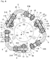
- Fig. 1 is a front view of the link actuating device, wherein a part thereof is omitted.
- the link actuating device includes: a parallel link mechanism 1; posture control actuators 50 that operate the parallel link mechanism 1; and a base 60 that supports the parallel link mechanism 1 and the posture control actuators 50.
- Fig. 2 is a diagram showing a state of the parallel link mechanism
- Fig. 3 is a diagram showing a different state of the parallel link mechanism.
- the parallel link mechanism 1 includes: a proximal end side link hub 2; a distal end side link hub 3; and three link mechanisms 4, in which the distal end side link hub 3 is coupled to the proximal end side link hub 2 via the three link mechanisms 4 such that the posture of the distal end side link hub 3 can be changed relative to the proximal end side link hub 2.
- Fig. 1 shows only one link mechanism 4. The number of link mechanisms 4 may be four or more.
- each link mechanism 4 includes: a proximal side end link member 5; a distal side end link member 6; and an intermediate link member 7, and forms a quadric chain link mechanism composed of four revolute pairs.
- the proximal side and distal side end link members 5 and 6 each have an L-shape.
- One end of the proximal side end link member 5 is rotatably coupled to the proximal end side link hub 2, and one end of the distal side end link member 6 is rotatably coupled to the distal end side link hub 3.
- the intermediate link member 7 has opposite ends to which the other ends of the proximal side and distal side end link members 5 and 6 are rotatably coupled, respectively.
- the parallel link mechanism 1 is formed by combining two spherical link mechanisms.
- the central axis of the revolute pair between the proximal end side link hub 2 and the proximal side end link member 5 and the central axis of the revolute pair between the proximal side end link member 5 and the intermediate link member 7 intersect each other at a proximal end side spherical link center PA ( Fig. 1 ).
- the central axis of the revolute pair between the distal end side link hub 3 and the distal side end link member 6 and the central axis of the revolute pair between the distal side end link member 6 and the intermediate link member 7 intersect each other at a distal end side spherical link center PB ( Fig.
- the distances from the proximal end side spherical link center PA to the revolute pairs between the proximal end side link hub 2 and the proximal side end link member 5 are equal to each other, and the distances from the proximal end side spherical link center PA to the revolute pairs between the proximal end link member 5 and the intermediate link member 7 are also equal to each other.
- the distances from the distal end side spherical link center PB to the revolute pairs between the distal end side link hub 3 and the distal side end link member 6 are equal to each other, and the distances from the distal end side spherical link center PB to the revolute pairs between the distal end link member 6 and the intermediate link member 7 are also equal to each other.
- the central axis of the revolute pair between the proximal end link member 5 and the intermediate link member 7, and the central axis of the revolute pair between the distal end link member 6 and the intermediate link member 7 may form a certain cross angle ⁇ ( Fig. 1 ), or may be parallel to each other.
- Fig. 4 is a cross-sectional view taken along a line IV-IV in Fig. 1 .
- Fig. 4 shows a relationship between the proximal end side spherical link center PA and the central axes O1 of the revolute pairs between the proximal end side link hub 2 and the proximal side end link members 5.
- Fig. 6 is a cross-sectional view taken along a line VI-VI in Fig. 1 .
- Fig. 6 shows a relationship between the distal end side spherical link center PB and the central axes O1 between the revolute pairs between the distal end side link hub 3 and the distal side end link members 6.
- Figs. 4 shows a cross-sectional view taken along a line IV-IV in Fig. 1 .
- Fig. 4 shows a relationship between the proximal end side spherical link center PA and the central axes O1 of the revolute pairs between the proximal end side link
- the angle ⁇ formed by the central axis O1 of the revolute pair between the proximal end side link hub 2 (the distal end side link hub 3) and the proximal side end link member 5 (the distal side end link member 6) and the central axis O2 of the revolute pair between the proximal side end link member 5 (the distal side end link member 6) and the intermediate link member 7 is set at 90°, but may be an angle other than 90°.
- the angle ⁇ is preferably 70° to 110° and more preferably 80° to 100°.
- the three link mechanisms 4 have a geometrically identical configuration.
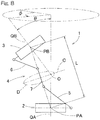
- the geometrically identical configuration means that, as shown in Fig. 8 , a geometric model depicted with straight lines representing the link members 5, 6, and 7, that is, a model depicted with the revolute pairs and straight lines connecting these revolute pairs, represents a shape in which the proximal end side portion thereof and the distal end side portion thereof are symmetrical with each other with respect to the center portion of the intermediate link member 7.
- Fig. 8 shows one link mechanism 4 depicted with straight lines.
- the parallel link mechanism 1 is of a rotation symmetrical type, and has a positional configuration in which the positional relationship between a proximal side portion composed of the proximal end side link hub 2 and the proximal side end link member 5, and a distal side portion composed of the distal end side link hub 3 and the distal side end link member 6, is in rotation symmetry relative to a center line C of the intermediate link member 7.
- the center portion of each intermediate link member 7 is located on a common orbital circle D.
- the proximal end side link hub 2, the distal end side link hub 3 and the three link mechanisms 4 cooperates together to form a two-degrees-of-freedom mechanism in which the distal end side link hub 3 is rotatable about two mutually orthogonal axes relative to the proximal end side link hub 2.
- the distal end side link hub 3 can rotate with two degrees of freedom to change its posture, relative to the proximal end side link hub 2.
- This two-degrees-of-freedom mechanism is compact in size, and also, can achieve a wide range of movement for the distal end side link hub 3 relative to the proximal end side link hub 2.
- an angle of traverse ⁇ ( Fig. 8 ) of the distal end side link hub 3 relative to the proximal end side link hub 2 can be set in the range of 0° to 360°.
- the bend angle ⁇ means a vertical angle formed when the central axis QB of the distal end side link hub 3 is inclined relative to the central axis QA of the proximal end side link hub 2.
- the angle of traverse ⁇ means a horizontal angle formed when the central axis QB of the distal end side link hub 3 is inclined relative to the central axis QA of the proximal end side link hub 2.
- Fig. 2 shows a state where the central axis QA of the proximal end side link hub 2 and the central axis QB of the distal end side link hub 3 are on the same line.
- Fig. 3 shows a state where the central axis QB of the distal end side link hub 3 forms a certain operating angle relative to the central axis QA of the proximal end side link hub 2.
- the proximal side portion composed of the proximal end side link hub 2 and each proximal side end link member 5 and the distal side portion composed of the distal end side link hub 3 and each distal side end link member 6 move in the same manner due to the geometrical symmetry.
- the conditions are: the angles of the central axis O1 of the revolute pair between the proximal end side link hub 2 (the distal end side link hub 3) and the proximal side end link member 5 (the distal side end link member 6) in each link mechanism 4 and the lengths from the proximal end side spherical link center PA (the distal end side spherical link center PB) to the revolute pair between the proximal end side link hub 2 (the distal end side link hub 3) and the proximal side end link member 5 (the distal side end link member 6) are equal to each other; the central axis O1 of the revolute pair between the proximal end side link hub 2 (the distal end side link hub 3) and the proximal side end link member 5 (the distal side end link member 6) of each link mechanism 4 and the central axis O2 of the revolute pair between the proximal side end link member 5 (the distal side end link member 6) and the
- the proximal end side link hub 2 includes a flat plate-shaped proximal end member 10 having a circular through hole 10a defined in a center portion thereof, and three rotation support members 11 provided equidistantly around the through hole 10a of the proximal end member 10 in the circumferential direction.
- the center of the through hole 10a is located on the central axis QA of the proximal end side link hub 2.
- Each rotation support member 11 has a pair of rotation support bodies 11a spaced apart from each other in the radial direction of the through hole 10a, and both ends of a rotation shaft 12 are rotatably supported by the pair of rotation support bodies 11a via bearings 13 so as to intersect the central axis QA ( Fig. 1 ) of the proximal end side link hub 2.
- the rotation shaft 12 is mounted to one end of the proximal side end link member 5.
- the one end of the proximal side end link member 5 is located between the pair of rotation support bodies 11a.
- Each bearing 13 is a ball bearing such as a deep groove ball bearing and an angular contact ball bearing.
- the bearing 13 is fixed to the rotation support body 11a by a method such as press-fit, adhesion, crimping or the like.
- the rotation shaft 12 may be rotatably supported by bringing the rotation shaft 12 into contact with the rotation support bodies 11a such that the rotation shaft 12 is rotatable.
- a rotation shaft 15 is mounted to the other end of the proximal side end link member 5.
- the rotation shaft 15 is rotatably supported by one end of the intermediate link member 7 via two bearings 16.
- the rotation shaft 15 may be rotatably supported by bringing the rotation shaft 15 into contact with the one end of the intermediate link member 7 such that the rotation shaft 15 is rotatable.
- the distal end side link hub 3 includes a flat plate-shaped distal end member 20 having a circular through hole 20a defined in a center portion thereof, and three rotation support members 21 provided equidistantly around the through hole 20a of the distal end member 20 in the circumferential direction.
- the center of the through hole 20a is located on the central axis QB of the distal end side link hub 3.
- a rotation shaft 22 is rotatably supported by each rotation support member 21 via bearings 23 so as to intersect the central axis QB ( Fig. 1 ) of the distal end side link hub 3.
- the rotation shaft 22 is mounted to one end of the distal side end link member 6.
- a rotation shaft 25 is mounted to the other end of the distal side end link member 6.
- the rotation shaft 25 is rotatably supported by the other end of the intermediate link member 7 via two bearings 26.
- the rotation shaft 25 may be rotatably supported by bringing the rotation shaft 25 into contact with the other end of the intermediate link member 7 such that the rotation shaft 25 is rotatable.
- proximal side and distal side end link members 5 and 6 will be described with reference to Fig. 5 , which is a partially enlarged view of Fig. 4 , and Fig. 7 , which is a partially enlarged view of Fig. 6 .
- the proximal side and distal side end link members 5 and 6 have the same configuration except for a part thereof.
- the proximal side end link member 5 will be described as a representative, and for the distal side end link 6, reference numerals for corresponding portions are described in parentheses. Portions different in configuration between the proximal side and distal side end link members 5 and 6 will be described as necessary.
- the proximal side end link member 5 (the distal side end link member 6) includes one bent portion 30, and a link hub side rotation shaft mounting portion 31A and an intermediate link side rotation shaft mounting portion 31B, both of which are fixed to opposite ends of the bent portion 30, respectively.
- each of the rotation shaft mounting portions 31A and 31B includes two rotation shaft mounting bodies 31a that are fixed to the outer-diameter-side surface and the inner-diameter-side surface of an end portion of the bent portion 30, respectively.
- the bent portion 30 is, for example, a casting made of a metallic material and has a shape bent at a predetermined angle ⁇ (90° in this example).
- the bending angle ⁇ may be arbitrarily determined.
- one bolt threaded hole 32 is provided so as to penetrate between the outer-diameter-side surface and the inner-diameter-side surface, and two positioning holes 33 are provided so as to be located at respective sides of the bolt threaded hole 32.
- Each of the rotation shaft mounting bodies 31a of the rotation shaft mounting portions 31A and 31B is formed in a predetermined shape by performing working such as sheet metal working on a plate-shaped member having a uniform thickness such as a metal plate.
- the shape of each rotation shaft mounting body 31a is, for example, an elongated straight shape, and each rotation shaft mounting body 31a is provided with one bolt insertion hole 34 corresponding to the bolt threaded hole 32 of the bent portion 30, two positioning holes 35 corresponding to the positioning holes 33 of the bent portion 30, and a through hole 36 through which any of the rotation shafts 12, 15, 22, and 25 is inserted.
- the rotation shaft mounting body 31a When a plate-shaped member having a simple shape and a uniform thickness is used as the raw material for each rotation shaft mounting body 31a, the rotation shaft mounting body 31a can be produced at low cost and the mass productivity thereof is excellent. Particularly, when the raw material is a metal plate, working for the contour shape and the respective holes 34, 35 and 36 is easy.
- a positioning pin 37 is inserted through the positioning hole 33 of the bent portion 30 and the positioning holes 35 of the respective rotation shaft mounting bodies 31a at the outer diameter side and the inner diameter side so as to position the bent portion 30 and the rotation shaft mounting body 31a.
- bolts 38 are inserted through the bolt insertion holes 34 of the respective rotation shaft mounting bodies 31a from the outer diameter side and the inner diameter side, respectively, and then, are screwed into the bolt threaded hole 32 of the bent portion 30.
- the rotation shaft mounting bodies 31a at the outer diameter side and the inner diameter side are individually fixed to the bent portion 30 by the bolts 38, which are different from each other, in a state where the rotation shaft mounting bodies 31a are positioned by the common positioning pin 37.
- the positioning pin 37 as described above, assembling is rendered to be easy, and variations in accuracy of assembling by a worker are reduced.
- the accuracy of the positional relationship between the bent portion 30 and each rotation shaft mounting body 31a improves, and thus, the parallel link mechanism 1 can be smoothly operated.
- a bevel gear 54 forming a part of a gear mechanism 52 ( Fig. 1 ) described later is disposed in the space between the two rotation shaft mounting bodies 31a at the outer diameter side and the inner diameter side, and the pair of rotation support bodies 11a of the rotation support member 11 are disposed radially outward of the rotation shaft mounting bodies 31a.
- the space between the two rotation shaft mounting bodies 31a at the outer diameter side and the inner diameter side is a space S sandwiched between two virtual planes obtained by extending the radially inner edge and the radially outer edge of one end of the bent portion 30 in the longitudinal direction of the rotation shaft mounting portion 31A.
- the proximal side end link member 5 and the rotation support member 11 are rotatably coupled to each other, and the proximal side end link member 5 and the bevel gear 54 are also coupled to each other so as to rotate integrally together.
- these components are coupled as follows.
- the rotation shaft 12 has, at an outer diameter end thereof, a head portion 12a having a larger diameter than the other portion, and has an external thread portion 12b at an inner diameter end thereof.
- the rotation shaft 12 is inserted, from the radially outer side, through respective through holes of the inner ring of the bearing 13 at the outer diameter side, a spacer 40, the rotation shaft mounting body 31a at the outer diameter side, the bevel gear 54, a spacer 41, the rotation shaft mounting body 31a at the inner diameter side, a spacer 42, the inner ring of the bearing 13 at the inner diameter side, and a spacer 43 in this order, and then, a nut 44 is screwed onto the external thread portion 12b.
- the inner rings of the two bearings 13, the two rotation shaft mounting bodies 31a, the one bevel gear 54 and the four spacers 40, 41, 42 and 43 are held between the head portion 12a of the rotation shaft 12 and the nut 44.
- the proximal side end link member 5, the rotation support member 11 and the bevel gear 54 are coupled, in a state where a preload is applied to the bearings 13.
- the rotation support member 21 is disposed between the two rotation shaft mounting bodies 31a at the outer diameter side and the inner diameter side.
- the distal side end link member 6 and the rotation support member 21 are rotatably coupled to each other via the rotation shaft 22. Specifically, these members are coupled as follows.
- the rotation shaft 22 has, at an outer diameter end thereof, a head portion 22a having a larger diameter than the other portion, and has an external thread portion 22b at an inner diameter end thereof.
- the rotation shaft 22 is inserted, from the radially outer side, through respective through holes of the rotation shaft mounting body 31a at the outer diameter side, a spacer 45, the inner rings of the two bearings 23, a spacer 46 and the rotation shaft mounting body 31a at the inner diameter side in this order, and then, a nut 47 is screwed onto the external thread portion 22b. Accordingly, the two rotation shaft mounting bodies 31a, the inner rings of the two bearings 23 and the two spacers 45 and 46 are held between the head portion 22a of the rotation shaft 22 and the nut 47. By so doing, the distal side end link member 6 and the rotation support member 21 are rotatably coupled to each other, in a state where a preload is applied to the bearings 23.
- one end (the other end) of the intermediate link member 7 is disposed between the two rotation shaft mounting bodies 31a at the outer diameter side and the inner diameter side.
- the proximal side end link member 5 (the distal side end link member 6) and the intermediate link member 7 are rotatably coupled to each other via the rotation shaft 15 (25). Specifically, these members are coupled as follows.
- the rotation shaft 15 (25) has, at an outer diameter end thereof, a head portion 15a (25a) having a larger diameter than the other portion, and has an external thread portion 15b (25b) at an inner diameter end thereof.
- the rotation shaft 15 (25) is inserted, from the radially outer side, through respective through holes of the rotation shaft mounting body 31a at the outer diameter side, the spacer 45, the inner rings of the two bearings 16 (26), the spacer 46 and the rotation shaft mounting body 31a at the inner diameter side in this order, and then, the nut 47 is screwed onto the external thread portion 15b (25b).
- the two rotation shaft mounting bodies 31a, the inner rings of the two bearings 16 (26) and the two spacers 45 and 46 are held between the head portion 15a (25a) of the rotation shaft 15 (25) and the nut 47.
- the proximal side end link member 5 (the distal side end link member 6) and the rotation support member 11 (21) are rotatably coupled to each other, in a state where a preload is applied to the bearings 16 (26).
- the base 60 includes a base plate 61 installed on a floor surface and a plurality of posts 62 provided so as to extend upward from the base plate 61.
- the proximal end member 10 of the parallel link mechanism 1 is supported on the upper ends of the plurality of posts 62.
- a plate-shaped motor mounting member 63 is horizontally provided at upper portions of the plurality of posts 62, and the posture control actuators 50 are mounted on the motor mounting member 63 in a suspended state.
- the number of the posture control actuators 50 is three, which is equal to the number of the link mechanisms 4 of the parallel link mechanism 1. However, when the posture control actuators 50 are provided to at least two of the three link mechanisms 4, the parallel link mechanism 1 can be operated.
- Each posture control actuator 50 includes a rotary motor which is provided with an accessory speed reduction mechanism 51.
- An output shaft 51a projects upward from the speed reduction mechanism 51.
- the gear mechanism 52 that serves as a speed reduction mechanism is provided.
- the gear mechanism 52 includes a driving bevel gear 53 mounted on the output shaft 51a of the speed reduction mechanism 51, and the driven bevel gear 54 mounted on the rotation shaft 12 at the revolute pair section between the proximal end side link hub 2 and the proximal side end link member 5.
- the link actuating device operates the parallel link mechanism 1 by rotationally driving each posture control actuator 50. Specifically, when each posture control actuator 50 is rotationally driven, the rotation of the actuator 50 is transmitted via the speed reduction mechanism 51 and the gear mechanism 52 to the rotation shaft 12 while the speed of the rotation is reduced. By so doing, the proximal side end link member 5 changes its angle, whereby the posture of the distal end side link hub 3 relative to the proximal end side link hub 2 is changed.
- the parallel link mechanism 1 has a configuration in which the distal end side link hub 3 is coupled to the proximal end side link hub 2 via the three quadric chain link mechanisms 4 such that the posture of the distal end side link hub 3 can be changed relative to the proximal end side link hub 2, the parallel link mechanism 1 is compact in size, and also, can operate at high speed with high accuracy in a wide operating range. Since the gear mechanism 52 serves as a speed reduction mechanism, it is possible to omit the accessory speed reduction mechanism 51 or use a small-sized speed reduction mechanism in the posture control actuator 50.
- each of the proximal side and distal side end link members 5 and 6 is bent at the bent portion 30, the overall length in the radial direction of the link actuating device can be shortened, and therefore, the link actuating device has a compact configuration.
- Each of the rotation shaft mounting portions 31A and 31B of the proximal side and distal side end link members 5 and 6 includes the two rotation shaft mounting bodies 31a. Since each rotation shaft mounting body 31a is composed of a metal plate detachably mounted on the bent portion 30, the rotation shaft mounting body 31a can be produced by sheet metal working at low cost with good mass productivity. By merely changing the size of the metal plate which is a raw material, the rotation shaft mounting body 31a is capable of handling a difference in size of the link actuating device. Thus, it is easy to change the size of the link actuating device.
- each section can be formed in a simple shape. Therefore, the working cost can be reduced and the mass productivity improves.
- the respective rotation shaft mounting bodies 31a of the rotation shaft mounting portions 31A and 31B are formed in shapes that are the same as each other, the components can be shared. As a result, the cost is low, and the mass productivity is good.
- the thicknesses or the shapes of the respective rotation shaft mounting bodies 31a may be made different from each other in accordance with the locations at which the rotation shaft mounting bodies 31a are used and the strength required for the rotation shaft mounting bodies 31a.
- the rotation shaft mounting bodies 31a used at the revolute pair section between the proximal end side link hub 2 and the proximal side end link member 5 are each formed in a shape in which a distal end portion thereof from the through hole 36 extends long in the longitudinal direction as compared to the rotation shaft mounting bodies 31a used at the other locations.
- the revolute pair section between the proximal end side link hub 2 and the proximal side end link member 5 has the following operation and effect. Since the bevel gear 54 forming a part of the gear mechanism 52 is disposed between the two rotation shaft mounting bodies 31a, the bearings 13 for supporting the rotation shaft 12 and the bearings 13 for supporting the bevel gear 54 can be shared, and thus, a more compact configuration is achieved.
- the bearings 13 that rotatably support both ends of the rotation shaft 12 are disposed at the outer side in the direction in which the two rotation shaft mounting bodies 31a are aligned, a moment load to the bearings 13 can be reduced, and thus, the rigidity of the link actuating device can be improved.
- the bearings 13 are disposed as described above, the bearings 13 for supporting the rotation shaft 12 and the bearings 13 for supporting the bevel gear 54 can be more easily shared.
- Fig. 9 shows a proximal side end link member having a configuration different from that shown in Fig. 5 .
- one rotation shaft mounting body 31a' (at the inner diameter side in this example) is formed so as to be integrated with the bent portion 30.
- a through hole 36 through which the rotation shaft 12 is inserted is provided in the rotation shaft mounting body 31a'.
- a positioning hole 33' is provided in the bent portion 30 and only in a surface on which the rotation shaft mounting body 31a that is a separate member is mounted (an outer diameter surface thereof in this example).
- the rotation shaft mounting body 31a is positioned by inserting a positioning pin 37' into the positioning hole 33'. With this configuration, only one rotation shaft mounting body 31a needs to be mounted on the bent portion 30, and thus assemblability improves.
- both of two rotation shaft mounting bodies 31a' of the rotation shaft mounting portion 31 may be formed so as to be integrated with the bent portion 30. In this case, work for mounting each rotation shaft mounting body 31a' to the bent portion 30 is unnecessary, and thus the assemblability further improves.
- the configurations in Fig. 9 and Fig. 10 are also applicable to the distal side end link member 6.
- Fig. 11 shows a rotation shaft mounting portion, at the link hub side of a proximal side end link member, having a configuration different from that shown in Fig. 5 .
- the rotation shaft mounting portion 31A shown in Fig. 11 by using rotation shaft mounting bodies 31a each formed into a bent shape by bending, the interval between the two rotation shaft mounting bodies 31a at a location where the rotation shaft 12 is mounted to the two rotation shaft mounting bodies 31a is made larger than that at a location where the two rotation shaft mounting bodies 31a are fixed to the bent portion 30. Accordingly, the space for installing the bevel gear 54 is widened, and thus, the assemblability improves.
- each of the two rotation shaft mounting bodies 31a is formed in a bent shape.
- only one of the rotation shaft mounting bodies 31a may be formed in a bent shape.
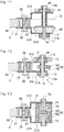
- Fig. 12 shows a rotation shaft mounting portion in the case where the gear mechanism includes a worm gear.
- the gear mechanism 52 composed of a worm gear includes a worm 55 mounted on the output shaft 51a (see Fig. 1 ) of the speed reduction mechanism 51, and a worm wheel 56 mounted on the rotation shaft 12 at the revolute pair section between the proximal end side link hub 2 (see Fig. 1 ) and the proximal side end link member 5.
- Rotation of the posture control actuator 50 (see Fig. 1 ) is transmitted via the worm 55 and the worm wheel 56 to the rotation shaft 12, thereby operating the proximal side end link member 5.
- the same operation and effect as those with the configuration shown in Fig. 5 are achieved.
- Examples of an axis-orthogonal type gear used for the gear mechanism 52 include, in addition to the bevel gear shown in Fig. 5 and the worm gear shown in Fig. 12 , a hypoid gear, and a screw gear.
- Fig. 13 shows an embodiment in which the configuration of a revolute pair section between a proximal end side link hub and a proximal side end link member is changed from that in the embodiment in Fig. 5 .
- a gear box 70 in which the gear mechanism 52 is accommodated is provided.
- the gear box 70 is fixed to the proximal end side link hub (not shown).
- the gear box 70 corresponds to the rotation support member 11 in the embodiment shown in Fig. 5 .
- a proximal end member (not shown) and the gear box 70 form the proximal end side link hub.
- a gear box input shaft 71 projects from the bottom surface of the gear box 70, and a gear box output shaft 72 projects from two opposite side surfaces of the gear box 70.
- the gear box input shaft 71 corresponds to the output shaft 51a (see Fig. 1 ) of the speed reduction mechanism 51 or a shaft coupled to the output shaft 51a.
- the gear box output shaft 72 is a rotation shaft at the revolute pair section between the proximal end side link hub 2 (see Fig. 1 ), and the proximal side end link member 5 (see Fig. 1 ) and corresponds to the rotation shaft 12 in the embodiment shown in Fig. 5 .
- the gear mechanism 52 includes the worm 55 and the worm wheel 56.
- the worm 55 forming a driving gear is mounted on the gear box input shaft 71
- the worm wheel 56 forming a driven gear is mounted on the gear box output shaft 72.
- the gear box output shaft 72 is rotatably supported by the gear box 70 via two bearings 73.
- the worm wheel 56 is located in a space S ( Fig. 13 ) sandwiched between two virtual planes obtained by extending the radially inner edge and the radially outer edge of one end of the bent portion 30 in the longitudinal direction of the rotation shaft mounting portion 31A.
- the gear mechanism 52, the rotation shaft or the gear box output shaft 72, and the bearings 73 are disposed together within the gear box 70, and therefore, it is easy to assemble the gear mechanism 52.
- the gear mechanism 52 is disposed within the gear box 70, improvement of safety, prevention of scattering of grease, prevention of entering of foreign matter into the gear mechanism 52 and the like can be achieved.
- the rotation shaft mounting portion 31A of the proximal side end link member 5 includes the two rotation shaft mounting bodies 31a (or 31a') that are disposed so as to oppose each other and to which the rotation shaft 12 or 72 is mounted, and the bevel gear 54 or the worm wheel 56, forming a part of the gear mechanism 52 ( Fig. 1 , Fig. 12, Fig. 13 ), is disposed between these two rotation shaft mounting bodies 31a.
- the rigidity of the rotation shaft mounting portion 31A is high as compared to the case where the rotation shaft mounting portion 31A is composed of one rotation shaft mounting body (not shown).
- the rotation shaft mounting portion 31A may be composed of one rotation shaft mounting body 31a.
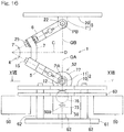
- Fig. 16 is a front view of a link actuating device according to another embodiment of the present invention, wherein a part thereof is omitted.
- Fig. 17 is a cross-sectional view taken along a line XVII-XVII in Fig. 16 .
- parts that are the same as or equivalent to the parts shown in corresponding Fig. 1 and Fig. 4 are designated by the same reference numerals, and some of the reference numerals are omitted for simplification.
- each posture control actuator 50 is mounted on the motor mounting member 63 such that an output shaft 50a thereof extends horizontally. Rotation of the horizontal output shaft 50a is transmitted via three spur gears 75, 76 and 77 to the rotation shaft 12. These three spur gears 75, 76 and 77 cooperate together to form the gear mechanism 52, and the gear mechanism 52 serves as a speed reduction mechanism.
- each posture control actuator 50 is not disposed on the same axis as the rotation shaft 12 but is disposed below the rotation shaft 12, a configuration can be achieved in which no component is present around the revolute pair section between the proximal side end link member 5 and the intermediate link member 7. Accordingly, the operating angle of the proximal side end link member 5 can be large, and therefore, the range where the posture of the distal end side link hub 3 relative to the proximal end side link hub 2 can be changed is widened.
Landscapes
- Engineering & Computer Science (AREA)
- Mechanical Engineering (AREA)
- Robotics (AREA)
- General Engineering & Computer Science (AREA)
- Transmission Devices (AREA)
- Manipulator (AREA)
Claims (6)
- Dispositif d'actionnement de liaison comprenant :un pivot de liaison de côté d'extrémité proximale (2) ;un pivot de liaison de côté d'extrémité distale (3) ;trois ou plus mécanismes de liaison (4) qui couplent le pivot de liaison de côté d'extrémité distale (3) au pivot de liaison de côté d'extrémité proximale (2) de telle sorte qu'une posture du pivot de liaison de côté d'extrémité distale (3) puisse être changée par rapport au pivot de liaison de côté d'extrémité proximale (2) ; etun actionneur de commande de posture (50) configuré pour changer arbitrairement la posture du pivot de liaison de côté d'extrémité distale (3) par rapport au pivot de liaison de côté d'extrémité proximale (2), l'actionneur de commande de posture (50) étant prévu pour chacun de deux ou plus mécanismes de liaison (4) des trois ou plus mécanismes de liaison (4), dans lequelchacun des mécanismes de liaison (4) inclut : un organe de liaison d'extrémité de côté proximal (5) ayant une extrémité couplée de manière rotative au pivot de liaison de côté d'extrémité proximale (2) ; un organe de liaison d'extrémité de côté distal (6) ayant une extrémité couplée de manière rotative au pivot de liaison de côté d'extrémité distale (3) ; et un organe de liaison intermédiaire (7) ayant des extrémités opposées couplées de manière rotative aux autres extrémités des organes de liaison d'extrémité de côté proximal et de côté distal (6), respectivement,l'organe de liaison d'extrémité de côté proximal (5) a une partie coudée (30) qui est coudée à un angle arbitraire et une partie de montage d'arbre de rotation (31A, 31B) qui est fixée à une extrémité de la partie coudée (30) et à laquelle un arbre de rotation (12, 15, 22, 25) situé à un axe d'une paire rotoïde entre le pivot de liaison de côté d'extrémité proximale (2) et l'organe de liaison d'extrémité de côté proximal (5) est monté, etau moins une partie d'un mécanisme d'engrenage (52) configuré pour transmettre un mouvement de rotation par l'actionneur de commande de posture (50) à l'organe de liaison d'extrémité de côté proximal (5) est montée sur la partie de montage d'arbre de rotation (31A, 31B) et disposée dans un espace (S) entre deux plans virtuels obtenus en étendant un bord radialement intérieur et un bord radialement extérieur de l'une extrémité de la partie coudée (30) dans une direction longitudinale de la partie de montage d'arbre de rotation (31A, 31B),caractérisé en ce que
la partie de montage d'arbre de rotation (31A, 31B) inclut deux corps de montage d'arbre de rotation (31a) qui sont disposés de manière à s'opposer l'un à l'autre et sur lesquels l'arbre de rotation (12, 15, 22, 25) est monté, et la au moins une partie du mécanisme d'engrenage (52) est disposée entre ces deux corps de montage d'arbre de rotation (31a). - Dispositif d'actionnement de liaison selon la revendication 1, dans lequel chacun des corps de montage d'arbre de rotation (31a) est composé d'un organe en forme de plaque monté de manière amovible sur la partie coudée (30).
- Dispositif d'actionnement de liaison selon la revendication 2, dans lequel les deux ou l'un des deux corps de montage d'arbre de rotation (31a) est formé avec une forme coudée de telle sorte qu'un intervalle entre les deux corps de montage d'arbre de rotation (31a) à un endroit où l'arbre de rotation (12, 15, 22, 25) est monté sur les deux corps de montage d'arbre de rotation (31a) soit plus grand que celui à un endroit où les deux corps de montage d'arbre de rotation (31a) sont fixés à la partie coudée (30).
- Dispositif d'actionnement de liaison selon l'une quelconque des revendications 1 à 3, dans lequel des paliers (13, 16) qui supportent de manière rotative les deux extrémités de l'arbre de rotation (12, 15, 22, 25) sont disposés sur un côté extérieur dans une direction dans laquelle les deux corps de montage d'arbre de rotation (31a) sont alignés.
- Dispositif d'actionnement de liaison selon l'une quelconque des revendications 1 à 4, dans lequel le mécanisme d'engrenage (52) comprend un mécanisme de réduction de vitesse configuré pour transmettre le mouvement de rotation par l'actionneur de commande de posture (50) à l'organe de liaison d'extrémité de côté proximal (5) tout en réduisant une vitesse du mouvement de rotation.
- Dispositif d'actionnement de liaison selon l'une quelconque des revendications 1 à 5, comprenant en outre une boîte d'engrenage (70) qui loge le mécanisme d'engrenage (52), dans lequel
la boîte d'engrenage (70) est fixée au pivot de liaison de côté d'extrémité proximale (2),
l'arbre de rotation (12, 15, 22, 25) est supporté de manière rotative par la boîte d'engrenage (70) via un palier (73),
un engrenage entraînant (55) du mécanisme d'engrenage (52) est monté sur un arbre d'entrée de boîte d'engrenage (71) couplé à l'actionneur de commande de posture (50), et
un engrenage entraîné (56) du mécanisme d'engrenage (52) est monté sur l'arbre de rotation (12, 15, 22, 25).
Applications Claiming Priority (2)
| Application Number | Priority Date | Filing Date | Title |
|---|---|---|---|
| JP2015250939A JP6262193B2 (ja) | 2015-12-24 | 2015-12-24 | リンク作動装置 |
| PCT/JP2016/087773 WO2017110739A1 (fr) | 2015-12-24 | 2016-12-19 | Dispositif d'actionnement de liaison |
Publications (3)
| Publication Number | Publication Date |
|---|---|
| EP3396204A1 EP3396204A1 (fr) | 2018-10-31 |
| EP3396204A4 EP3396204A4 (fr) | 2019-08-14 |
| EP3396204B1 true EP3396204B1 (fr) | 2021-04-21 |
Family
ID=59090344
Family Applications (1)
| Application Number | Title | Priority Date | Filing Date |
|---|---|---|---|
| EP16878628.3A Active EP3396204B1 (fr) | 2015-12-24 | 2016-12-19 | Dispositif d'actionnement de liaison |
Country Status (5)
| Country | Link |
|---|---|
| US (1) | US10780574B2 (fr) |
| EP (1) | EP3396204B1 (fr) |
| JP (1) | JP6262193B2 (fr) |
| CN (1) | CN108463651B (fr) |
| WO (1) | WO2017110739A1 (fr) |
Families Citing this family (5)
| Publication number | Priority date | Publication date | Assignee | Title |
|---|---|---|---|---|
| JP6262193B2 (ja) * | 2015-12-24 | 2018-01-17 | Ntn株式会社 | リンク作動装置 |
| JP6719956B2 (ja) * | 2016-04-20 | 2020-07-08 | Ntn株式会社 | 双腕型作動装置 |
| CN109312834B (zh) | 2016-06-08 | 2021-08-10 | Ntn株式会社 | 连杆促动装置 |
| JP7022008B2 (ja) * | 2018-06-08 | 2022-02-17 | Ntn株式会社 | リンク作動装置 |
| CN113183164A (zh) * | 2021-05-10 | 2021-07-30 | 上海工程技术大学 | 一种基于曲柄摇杆机构的仿生机械牛及控制方法 |
Family Cites Families (17)
| Publication number | Priority date | Publication date | Assignee | Title |
|---|---|---|---|---|
| DE8214938U1 (de) * | 1982-05-22 | 1983-07-28 | Jungheinrich Unternehmensverwaltung Kg, 2000 Hamburg | Gelenkkopf für Industrieroboter |
| JPH08216072A (ja) * | 1995-02-20 | 1996-08-27 | Tokico Ltd | 工業用ロボット |
| US5893296A (en) | 1997-03-13 | 1999-04-13 | Ross-Hime Designs, Incorporated | Multiple rotatable links robotic manipulator |
| JP2000094245A (ja) | 1998-09-17 | 2000-04-04 | Fanuc Ltd | パラレルリンク機構を具備する作業装置 |
| JP2004009276A (ja) * | 2002-06-11 | 2004-01-15 | Ntn Corp | リンク作動装置 |
| JP2005127475A (ja) * | 2003-10-27 | 2005-05-19 | Ntn Corp | リンク作動装置 |
| JP2005144627A (ja) * | 2003-11-18 | 2005-06-09 | Ntn Corp | リンク作動装置 |
| JP5301934B2 (ja) * | 2008-09-19 | 2013-09-25 | 川崎重工業株式会社 | ロボットハンドの駆動機構 |
| CN102059696B (zh) * | 2009-11-18 | 2013-11-20 | 鸿富锦精密工业(深圳)有限公司 | 并联机构 |
| JP2013068280A (ja) * | 2011-09-22 | 2013-04-18 | Ntn Corp | リンク作動装置 |
| JP5951224B2 (ja) | 2011-11-02 | 2016-07-13 | Ntn株式会社 | リンク作動装置の原点位置初期設定方法およびリンク作動装置 |
| CN102909727B (zh) * | 2012-10-18 | 2015-02-18 | 清华大学 | 分立式三电机协同复合抓取机器人手指装置 |
| JP6289973B2 (ja) | 2014-03-31 | 2018-03-07 | Ntn株式会社 | パラレルリンク機構およびリンク作動装置 |
| CN104440869B (zh) * | 2014-09-24 | 2016-04-20 | 哈尔滨工业大学 | 三自由度并联差分式机器人关节 |
| US20180236668A1 (en) * | 2015-10-27 | 2018-08-23 | Panasonic Intellectual Property Management Co., Lt | Carrier device |
| JP6262193B2 (ja) * | 2015-12-24 | 2018-01-17 | Ntn株式会社 | リンク作動装置 |
| JP6275196B2 (ja) * | 2016-06-05 | 2018-02-07 | Ntn株式会社 | リンク作動装置の操作装置およびリンク作動システム |
-
2015
- 2015-12-24 JP JP2015250939A patent/JP6262193B2/ja active Active
-
2016
- 2016-12-19 EP EP16878628.3A patent/EP3396204B1/fr active Active
- 2016-12-19 CN CN201680075622.8A patent/CN108463651B/zh active Active
- 2016-12-19 WO PCT/JP2016/087773 patent/WO2017110739A1/fr active Application Filing
-
2018
- 2018-06-14 US US16/008,581 patent/US10780574B2/en active Active
Non-Patent Citations (1)
| Title |
|---|
| None * |
Also Published As
| Publication number | Publication date |
|---|---|
| US20180290294A1 (en) | 2018-10-11 |
| EP3396204A1 (fr) | 2018-10-31 |
| CN108463651A (zh) | 2018-08-28 |
| JP2017115954A (ja) | 2017-06-29 |
| WO2017110739A1 (fr) | 2017-06-29 |
| JP6262193B2 (ja) | 2018-01-17 |
| CN108463651B (zh) | 2021-11-23 |
| US10780574B2 (en) | 2020-09-22 |
| EP3396204A4 (fr) | 2019-08-14 |
Similar Documents
| Publication | Publication Date | Title |
|---|---|---|
| US10780574B2 (en) | Link actuating device | |
| US10406677B2 (en) | Parallel link mechanism and link actuation device | |
| US10022827B2 (en) | Method for initially setting position of origin of link actuators, and link actuator | |
| US9243696B2 (en) | Link actuating device | |
| EP3354420B1 (fr) | Dispositif d'actionnement à biellette de type combiné | |
| EP2998081B1 (fr) | Dispositif d'actionnement de liaison | |
| US9394979B2 (en) | Link actuating device | |
| EP3816477B1 (fr) | Dispositif d'actionnement d'articulation | |
| US11000946B2 (en) | Link operating device | |
| EP3336381B1 (fr) | Machine de travail à mécanisme de liaison parallèle | |
| JP2014061571A (ja) | ユニバーサルジョイント、及びそれを備えたパラレルリンクロボット | |
| JP2018194056A (ja) | リンク作動装置 | |
| WO2015182557A1 (fr) | Mécanisme de liaison parallèle et dispositif de fonctionnement de liaison | |
| JP6352054B2 (ja) | パラレルリンク機構およびリンク作動装置 | |
| JP6534751B1 (ja) | パラレルリンク機構およびリンク作動装置 |
Legal Events
| Date | Code | Title | Description |
|---|---|---|---|
| STAA | Information on the status of an ep patent application or granted ep patent |
Free format text: STATUS: THE INTERNATIONAL PUBLICATION HAS BEEN MADE |
|
| PUAI | Public reference made under article 153(3) epc to a published international application that has entered the european phase |
Free format text: ORIGINAL CODE: 0009012 |
|
| STAA | Information on the status of an ep patent application or granted ep patent |
Free format text: STATUS: REQUEST FOR EXAMINATION WAS MADE |
|
| 17P | Request for examination filed |
Effective date: 20180618 |
|
| AK | Designated contracting states |
Kind code of ref document: A1 Designated state(s): AL AT BE BG CH CY CZ DE DK EE ES FI FR GB GR HR HU IE IS IT LI LT LU LV MC MK MT NL NO PL PT RO RS SE SI SK SM TR |
|
| AX | Request for extension of the european patent |
Extension state: BA ME |
|
| DAV | Request for validation of the european patent (deleted) | ||
| DAX | Request for extension of the european patent (deleted) | ||
| A4 | Supplementary search report drawn up and despatched |
Effective date: 20190711 |
|
| RIC1 | Information provided on ipc code assigned before grant |
Ipc: B25J 11/00 20060101ALI20190705BHEP Ipc: B25J 9/10 20060101ALI20190705BHEP Ipc: F16H 21/50 20060101AFI20190705BHEP Ipc: B25J 9/00 20060101ALI20190705BHEP |
|
| REG | Reference to a national code |
Ref country code: DE Ref legal event code: R079 Ref document number: 602016056678 Country of ref document: DE Free format text: PREVIOUS MAIN CLASS: F16H0021500000 Ipc: F16H0021480000 |
|
| GRAP | Despatch of communication of intention to grant a patent |
Free format text: ORIGINAL CODE: EPIDOSNIGR1 |
|
| STAA | Information on the status of an ep patent application or granted ep patent |
Free format text: STATUS: GRANT OF PATENT IS INTENDED |
|
| RIC1 | Information provided on ipc code assigned before grant |
Ipc: B25J 9/00 20060101ALI20201030BHEP Ipc: F16H 21/48 20060101AFI20201030BHEP Ipc: B25J 9/10 20060101ALI20201030BHEP Ipc: B25J 11/00 20060101ALI20201030BHEP |
|
| INTG | Intention to grant announced |
Effective date: 20201117 |
|
| GRAS | Grant fee paid |
Free format text: ORIGINAL CODE: EPIDOSNIGR3 |
|
| GRAA | (expected) grant |
Free format text: ORIGINAL CODE: 0009210 |
|
| STAA | Information on the status of an ep patent application or granted ep patent |
Free format text: STATUS: THE PATENT HAS BEEN GRANTED |
|
| AK | Designated contracting states |
Kind code of ref document: B1 Designated state(s): AL AT BE BG CH CY CZ DE DK EE ES FI FR GB GR HR HU IE IS IT LI LT LU LV MC MK MT NL NO PL PT RO RS SE SI SK SM TR |
|
| REG | Reference to a national code |
Ref country code: GB Ref legal event code: FG4D |
|
| REG | Reference to a national code |
Ref country code: CH Ref legal event code: EP |
|
| REG | Reference to a national code |
Ref country code: DE Ref legal event code: R096 Ref document number: 602016056678 Country of ref document: DE Ref country code: IE Ref legal event code: FG4D |
|
| REG | Reference to a national code |
Ref country code: AT Ref legal event code: REF Ref document number: 1384961 Country of ref document: AT Kind code of ref document: T Effective date: 20210515 |
|
| REG | Reference to a national code |
Ref country code: LT Ref legal event code: MG9D |
|
| REG | Reference to a national code |
Ref country code: AT Ref legal event code: MK05 Ref document number: 1384961 Country of ref document: AT Kind code of ref document: T Effective date: 20210421 |
|
| REG | Reference to a national code |
Ref country code: NL Ref legal event code: MP Effective date: 20210421 |
|
| PG25 | Lapsed in a contracting state [announced via postgrant information from national office to epo] |
Ref country code: LT Free format text: LAPSE BECAUSE OF FAILURE TO SUBMIT A TRANSLATION OF THE DESCRIPTION OR TO PAY THE FEE WITHIN THE PRESCRIBED TIME-LIMIT Effective date: 20210421 Ref country code: FI Free format text: LAPSE BECAUSE OF FAILURE TO SUBMIT A TRANSLATION OF THE DESCRIPTION OR TO PAY THE FEE WITHIN THE PRESCRIBED TIME-LIMIT Effective date: 20210421 Ref country code: NL Free format text: LAPSE BECAUSE OF FAILURE TO SUBMIT A TRANSLATION OF THE DESCRIPTION OR TO PAY THE FEE WITHIN THE PRESCRIBED TIME-LIMIT Effective date: 20210421 Ref country code: HR Free format text: LAPSE BECAUSE OF FAILURE TO SUBMIT A TRANSLATION OF THE DESCRIPTION OR TO PAY THE FEE WITHIN THE PRESCRIBED TIME-LIMIT Effective date: 20210421 Ref country code: BG Free format text: LAPSE BECAUSE OF FAILURE TO SUBMIT A TRANSLATION OF THE DESCRIPTION OR TO PAY THE FEE WITHIN THE PRESCRIBED TIME-LIMIT Effective date: 20210721 Ref country code: AT Free format text: LAPSE BECAUSE OF FAILURE TO SUBMIT A TRANSLATION OF THE DESCRIPTION OR TO PAY THE FEE WITHIN THE PRESCRIBED TIME-LIMIT Effective date: 20210421 |
|
| PG25 | Lapsed in a contracting state [announced via postgrant information from national office to epo] |
Ref country code: LV Free format text: LAPSE BECAUSE OF FAILURE TO SUBMIT A TRANSLATION OF THE DESCRIPTION OR TO PAY THE FEE WITHIN THE PRESCRIBED TIME-LIMIT Effective date: 20210421 Ref country code: IS Free format text: LAPSE BECAUSE OF FAILURE TO SUBMIT A TRANSLATION OF THE DESCRIPTION OR TO PAY THE FEE WITHIN THE PRESCRIBED TIME-LIMIT Effective date: 20210821 Ref country code: GR Free format text: LAPSE BECAUSE OF FAILURE TO SUBMIT A TRANSLATION OF THE DESCRIPTION OR TO PAY THE FEE WITHIN THE PRESCRIBED TIME-LIMIT Effective date: 20210722 Ref country code: PT Free format text: LAPSE BECAUSE OF FAILURE TO SUBMIT A TRANSLATION OF THE DESCRIPTION OR TO PAY THE FEE WITHIN THE PRESCRIBED TIME-LIMIT Effective date: 20210823 Ref country code: NO Free format text: LAPSE BECAUSE OF FAILURE TO SUBMIT A TRANSLATION OF THE DESCRIPTION OR TO PAY THE FEE WITHIN THE PRESCRIBED TIME-LIMIT Effective date: 20210721 Ref country code: PL Free format text: LAPSE BECAUSE OF FAILURE TO SUBMIT A TRANSLATION OF THE DESCRIPTION OR TO PAY THE FEE WITHIN THE PRESCRIBED TIME-LIMIT Effective date: 20210421 Ref country code: SE Free format text: LAPSE BECAUSE OF FAILURE TO SUBMIT A TRANSLATION OF THE DESCRIPTION OR TO PAY THE FEE WITHIN THE PRESCRIBED TIME-LIMIT Effective date: 20210421 Ref country code: RS Free format text: LAPSE BECAUSE OF FAILURE TO SUBMIT A TRANSLATION OF THE DESCRIPTION OR TO PAY THE FEE WITHIN THE PRESCRIBED TIME-LIMIT Effective date: 20210421 |
|
| REG | Reference to a national code |
Ref country code: DE Ref legal event code: R097 Ref document number: 602016056678 Country of ref document: DE |
|
| PG25 | Lapsed in a contracting state [announced via postgrant information from national office to epo] |
Ref country code: ES Free format text: LAPSE BECAUSE OF FAILURE TO SUBMIT A TRANSLATION OF THE DESCRIPTION OR TO PAY THE FEE WITHIN THE PRESCRIBED TIME-LIMIT Effective date: 20210421 Ref country code: RO Free format text: LAPSE BECAUSE OF FAILURE TO SUBMIT A TRANSLATION OF THE DESCRIPTION OR TO PAY THE FEE WITHIN THE PRESCRIBED TIME-LIMIT Effective date: 20210421 Ref country code: CZ Free format text: LAPSE BECAUSE OF FAILURE TO SUBMIT A TRANSLATION OF THE DESCRIPTION OR TO PAY THE FEE WITHIN THE PRESCRIBED TIME-LIMIT Effective date: 20210421 Ref country code: EE Free format text: LAPSE BECAUSE OF FAILURE TO SUBMIT A TRANSLATION OF THE DESCRIPTION OR TO PAY THE FEE WITHIN THE PRESCRIBED TIME-LIMIT Effective date: 20210421 Ref country code: DK Free format text: LAPSE BECAUSE OF FAILURE TO SUBMIT A TRANSLATION OF THE DESCRIPTION OR TO PAY THE FEE WITHIN THE PRESCRIBED TIME-LIMIT Effective date: 20210421 Ref country code: SK Free format text: LAPSE BECAUSE OF FAILURE TO SUBMIT A TRANSLATION OF THE DESCRIPTION OR TO PAY THE FEE WITHIN THE PRESCRIBED TIME-LIMIT Effective date: 20210421 Ref country code: SM Free format text: LAPSE BECAUSE OF FAILURE TO SUBMIT A TRANSLATION OF THE DESCRIPTION OR TO PAY THE FEE WITHIN THE PRESCRIBED TIME-LIMIT Effective date: 20210421 |
|
| PLBE | No opposition filed within time limit |
Free format text: ORIGINAL CODE: 0009261 |
|
| STAA | Information on the status of an ep patent application or granted ep patent |
Free format text: STATUS: NO OPPOSITION FILED WITHIN TIME LIMIT |
|
| 26N | No opposition filed |
Effective date: 20220124 |
|
| PG25 | Lapsed in a contracting state [announced via postgrant information from national office to epo] |
Ref country code: IS Free format text: LAPSE BECAUSE OF FAILURE TO SUBMIT A TRANSLATION OF THE DESCRIPTION OR TO PAY THE FEE WITHIN THE PRESCRIBED TIME-LIMIT Effective date: 20210821 Ref country code: AL Free format text: LAPSE BECAUSE OF FAILURE TO SUBMIT A TRANSLATION OF THE DESCRIPTION OR TO PAY THE FEE WITHIN THE PRESCRIBED TIME-LIMIT Effective date: 20210421 |
|
| PG25 | Lapsed in a contracting state [announced via postgrant information from national office to epo] |
Ref country code: MC Free format text: LAPSE BECAUSE OF FAILURE TO SUBMIT A TRANSLATION OF THE DESCRIPTION OR TO PAY THE FEE WITHIN THE PRESCRIBED TIME-LIMIT Effective date: 20210421 Ref country code: IT Free format text: LAPSE BECAUSE OF FAILURE TO SUBMIT A TRANSLATION OF THE DESCRIPTION OR TO PAY THE FEE WITHIN THE PRESCRIBED TIME-LIMIT Effective date: 20210421 |
|
| REG | Reference to a national code |
Ref country code: CH Ref legal event code: PL |
|
| GBPC | Gb: european patent ceased through non-payment of renewal fee |
Effective date: 20211219 |
|
| REG | Reference to a national code |
Ref country code: BE Ref legal event code: MM Effective date: 20211231 |
|
| PG25 | Lapsed in a contracting state [announced via postgrant information from national office to epo] |
Ref country code: LU Free format text: LAPSE BECAUSE OF NON-PAYMENT OF DUE FEES Effective date: 20211219 Ref country code: IE Free format text: LAPSE BECAUSE OF NON-PAYMENT OF DUE FEES Effective date: 20211219 Ref country code: GB Free format text: LAPSE BECAUSE OF NON-PAYMENT OF DUE FEES Effective date: 20211219 |
|
| PG25 | Lapsed in a contracting state [announced via postgrant information from national office to epo] |
Ref country code: BE Free format text: LAPSE BECAUSE OF NON-PAYMENT OF DUE FEES Effective date: 20211231 |
|
| PG25 | Lapsed in a contracting state [announced via postgrant information from national office to epo] |
Ref country code: LI Free format text: LAPSE BECAUSE OF NON-PAYMENT OF DUE FEES Effective date: 20211231 Ref country code: CH Free format text: LAPSE BECAUSE OF NON-PAYMENT OF DUE FEES Effective date: 20211231 |
|
| PG25 | Lapsed in a contracting state [announced via postgrant information from national office to epo] |
Ref country code: CY Free format text: LAPSE BECAUSE OF FAILURE TO SUBMIT A TRANSLATION OF THE DESCRIPTION OR TO PAY THE FEE WITHIN THE PRESCRIBED TIME-LIMIT Effective date: 20210421 |
|
| PG25 | Lapsed in a contracting state [announced via postgrant information from national office to epo] |
Ref country code: HU Free format text: LAPSE BECAUSE OF FAILURE TO SUBMIT A TRANSLATION OF THE DESCRIPTION OR TO PAY THE FEE WITHIN THE PRESCRIBED TIME-LIMIT; INVALID AB INITIO Effective date: 20161219 |
|
| PGFP | Annual fee paid to national office [announced via postgrant information from national office to epo] |
Ref country code: FR Payment date: 20231108 Year of fee payment: 8 Ref country code: DE Payment date: 20231031 Year of fee payment: 8 |
|
| PG25 | Lapsed in a contracting state [announced via postgrant information from national office to epo] |
Ref country code: MK Free format text: LAPSE BECAUSE OF FAILURE TO SUBMIT A TRANSLATION OF THE DESCRIPTION OR TO PAY THE FEE WITHIN THE PRESCRIBED TIME-LIMIT Effective date: 20210421 |