EP3393873B1 - Verfahren für die regelung und die wiederherstellung der adhäsion der räder einer geregelten achse eines schienenfahrzeuges - Google Patents
Verfahren für die regelung und die wiederherstellung der adhäsion der räder einer geregelten achse eines schienenfahrzeuges Download PDFInfo
- Publication number
- EP3393873B1 EP3393873B1 EP16834112.1A EP16834112A EP3393873B1 EP 3393873 B1 EP3393873 B1 EP 3393873B1 EP 16834112 A EP16834112 A EP 16834112A EP 3393873 B1 EP3393873 B1 EP 3393873B1
- Authority
- EP
- European Patent Office
- Prior art keywords
- speed
- signal
- wheels
- axle
- error
- Prior art date
- Legal status (The legal status is an assumption and is not a legal conclusion. Google has not performed a legal analysis and makes no representation as to the accuracy of the status listed.)
- Active
Links
Images


Classifications
-
- B—PERFORMING OPERATIONS; TRANSPORTING
- B60—VEHICLES IN GENERAL
- B60T—VEHICLE BRAKE CONTROL SYSTEMS OR PARTS THEREOF; BRAKE CONTROL SYSTEMS OR PARTS THEREOF, IN GENERAL; ARRANGEMENT OF BRAKING ELEMENTS ON VEHICLES IN GENERAL; PORTABLE DEVICES FOR PREVENTING UNWANTED MOVEMENT OF VEHICLES; VEHICLE MODIFICATIONS TO FACILITATE COOLING OF BRAKES
- B60T8/00—Arrangements for adjusting wheel-braking force to meet varying vehicular or ground-surface conditions, e.g. limiting or varying distribution of braking force
- B60T8/17—Using electrical or electronic regulation means to control braking
-
- B—PERFORMING OPERATIONS; TRANSPORTING
- B60—VEHICLES IN GENERAL
- B60L—PROPULSION OF ELECTRICALLY-PROPELLED VEHICLES; SUPPLYING ELECTRIC POWER FOR AUXILIARY EQUIPMENT OF ELECTRICALLY-PROPELLED VEHICLES; ELECTRODYNAMIC BRAKE SYSTEMS FOR VEHICLES IN GENERAL; MAGNETIC SUSPENSION OR LEVITATION FOR VEHICLES; MONITORING OPERATING VARIABLES OF ELECTRICALLY-PROPELLED VEHICLES; ELECTRIC SAFETY DEVICES FOR ELECTRICALLY-PROPELLED VEHICLES
- B60L3/00—Electric devices on electrically-propelled vehicles for safety purposes; Monitoring operating variables, e.g. speed, deceleration or energy consumption
- B60L3/10—Indicating wheel slip ; Correction of wheel slip
- B60L3/106—Indicating wheel slip ; Correction of wheel slip for maintaining or recovering the adhesion of the drive wheels
-
- B—PERFORMING OPERATIONS; TRANSPORTING
- B60—VEHICLES IN GENERAL
- B60L—PROPULSION OF ELECTRICALLY-PROPELLED VEHICLES; SUPPLYING ELECTRIC POWER FOR AUXILIARY EQUIPMENT OF ELECTRICALLY-PROPELLED VEHICLES; ELECTRODYNAMIC BRAKE SYSTEMS FOR VEHICLES IN GENERAL; MAGNETIC SUSPENSION OR LEVITATION FOR VEHICLES; MONITORING OPERATING VARIABLES OF ELECTRICALLY-PROPELLED VEHICLES; ELECTRIC SAFETY DEVICES FOR ELECTRICALLY-PROPELLED VEHICLES
- B60L3/00—Electric devices on electrically-propelled vehicles for safety purposes; Monitoring operating variables, e.g. speed, deceleration or energy consumption
- B60L3/10—Indicating wheel slip ; Correction of wheel slip
-
- B—PERFORMING OPERATIONS; TRANSPORTING
- B60—VEHICLES IN GENERAL
- B60T—VEHICLE BRAKE CONTROL SYSTEMS OR PARTS THEREOF; BRAKE CONTROL SYSTEMS OR PARTS THEREOF, IN GENERAL; ARRANGEMENT OF BRAKING ELEMENTS ON VEHICLES IN GENERAL; PORTABLE DEVICES FOR PREVENTING UNWANTED MOVEMENT OF VEHICLES; VEHICLE MODIFICATIONS TO FACILITATE COOLING OF BRAKES
- B60T17/00—Component parts, details, or accessories of power brake systems not covered by groups B60T8/00, B60T13/00 or B60T15/00, or presenting other characteristic features
- B60T17/18—Safety devices; Monitoring
- B60T17/22—Devices for monitoring or checking brake systems; Signal devices
- B60T17/228—Devices for monitoring or checking brake systems; Signal devices for railway vehicles
-
- B—PERFORMING OPERATIONS; TRANSPORTING
- B60—VEHICLES IN GENERAL
- B60T—VEHICLE BRAKE CONTROL SYSTEMS OR PARTS THEREOF; BRAKE CONTROL SYSTEMS OR PARTS THEREOF, IN GENERAL; ARRANGEMENT OF BRAKING ELEMENTS ON VEHICLES IN GENERAL; PORTABLE DEVICES FOR PREVENTING UNWANTED MOVEMENT OF VEHICLES; VEHICLE MODIFICATIONS TO FACILITATE COOLING OF BRAKES
- B60T8/00—Arrangements for adjusting wheel-braking force to meet varying vehicular or ground-surface conditions, e.g. limiting or varying distribution of braking force
- B60T8/17—Using electrical or electronic regulation means to control braking
- B60T8/1701—Braking or traction control means specially adapted for particular types of vehicles
- B60T8/1705—Braking or traction control means specially adapted for particular types of vehicles for rail vehicles
-
- B—PERFORMING OPERATIONS; TRANSPORTING
- B60—VEHICLES IN GENERAL
- B60T—VEHICLE BRAKE CONTROL SYSTEMS OR PARTS THEREOF; BRAKE CONTROL SYSTEMS OR PARTS THEREOF, IN GENERAL; ARRANGEMENT OF BRAKING ELEMENTS ON VEHICLES IN GENERAL; PORTABLE DEVICES FOR PREVENTING UNWANTED MOVEMENT OF VEHICLES; VEHICLE MODIFICATIONS TO FACILITATE COOLING OF BRAKES
- B60T8/00—Arrangements for adjusting wheel-braking force to meet varying vehicular or ground-surface conditions, e.g. limiting or varying distribution of braking force
- B60T8/17—Using electrical or electronic regulation means to control braking
- B60T8/172—Determining control parameters used in the regulation, e.g. by calculations involving measured or detected parameters
-
- G—PHYSICS
- G05—CONTROLLING; REGULATING
- G05F—SYSTEMS FOR REGULATING ELECTRIC OR MAGNETIC VARIABLES
- G05F1/00—Automatic systems in which deviations of an electric quantity from one or more predetermined values are detected at the output of the system and fed back to a device within the system to restore the detected quantity to its predetermined value or values, i.e. retroactive systems
-
- B—PERFORMING OPERATIONS; TRANSPORTING
- B60—VEHICLES IN GENERAL
- B60Q—ARRANGEMENT OF SIGNALLING OR LIGHTING DEVICES, THE MOUNTING OR SUPPORTING THEREOF OR CIRCUITS THEREFOR, FOR VEHICLES IN GENERAL
- B60Q1/00—Arrangement of optical signalling or lighting devices, the mounting or supporting thereof or circuits therefor
- B60Q1/26—Arrangement of optical signalling or lighting devices, the mounting or supporting thereof or circuits therefor the devices being primarily intended to indicate the vehicle, or parts thereof, or to give signals, to other traffic
- B60Q1/44—Arrangement of optical signalling or lighting devices, the mounting or supporting thereof or circuits therefor the devices being primarily intended to indicate the vehicle, or parts thereof, or to give signals, to other traffic for indicating braking action or preparation for braking, e.g. by detection of the foot approaching the brake pedal
- B60Q1/445—Arrangement of optical signalling or lighting devices, the mounting or supporting thereof or circuits therefor the devices being primarily intended to indicate the vehicle, or parts thereof, or to give signals, to other traffic for indicating braking action or preparation for braking, e.g. by detection of the foot approaching the brake pedal controlled by inertial devices
- B60Q1/447—Arrangement of optical signalling or lighting devices, the mounting or supporting thereof or circuits therefor the devices being primarily intended to indicate the vehicle, or parts thereof, or to give signals, to other traffic for indicating braking action or preparation for braking, e.g. by detection of the foot approaching the brake pedal controlled by inertial devices with indication of the braking strength or speed changes, e.g. by changing the shape or intensity of the indication
Definitions
- the present invention relates to a system for controlling and recovering the adhesion of the wheels of a controlled axle of a railway vehicle.
- Wheel slide control subsystems intended to intervene both when the vehicle is in the traction phase and when it is in the braking phase.
- These subsystems are known as anti-skid or anti-slide systems, or also WSP (Wheel Slide Protection) systems.
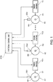
- FIG. 1 A system for controlling the adhesion of the wheels, in an anti-slip function, is schematically represented in figure 1 of the accompanying drawings, which refers to a vehicle with n controlled axles A1, A2, ..., An.
- the axles A1, A2, ..., An comprise a respective shaft SI, S2, ..., Sn and a respective pair of wheels W1, W2, ..., Wn integral in rotation to it.
- the WSP system of Figure 1 comprises an electronic control unit ECU, typically based on microprocessor architecture, that receives tachometer signals relating to the angular speed of each axle A1, A2, ...An from detectors SSI, SS2, ... , SSn respectively associated with these axles.
- the electronic control unit ECU is also connected to the torque control apparatuses TC1, TC2, ..., TCn, each associated with a respective axle A1, A2, ..., An.
- the electronic control unit ECU is provided to operate the modulation of the torque applied to each axle according to a predetermined algorithm if, in case of applying torque during traction or braking in a degraded adhesion situation, the wheels of one or more axles end up in a possible incipient slipping condition.
- Torque modulation is implemented in such a way as to prevent a total blocking of the axles, possibly so as to bring each axle into a situation of controlled sliding in view of recovering adhesion and in any case during the entire duration of the degraded adhesion situation.
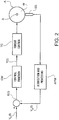
- FIG. 2 shows a block diagram illustrating the control implemented on a single axle: the error or difference E(t) between the reference speed value V R (t) at which one wishes to slide the controlled axle A and the angular measured velocity V M (t) detected by the associated sensor SS and conditioned by an acquisition and processing module APM is applied as an input signal to a control module CM, which provides as output a driving signal Y(t) to the torque control apparatus TC associated with the axle A.
- FIG. 3 illustrates by way of non-limiting example a possible way to realize the torque control apparatus TC.
- Such apparatus comprises an electronic control and driving unit 100, which controls a solenoid valve group 101 including a charging solenoid valve 102 and a discharging solenoid valve 103.
- these solenoid valves are three-way valves with two positions.
- the solenoid valve 102 is normally open, and the solenoid valve 103 is normally closed.
- the output of the charging solenoid valve 102 is coupled, in a manner known per se, to a brake cylinder 104 associated with the axle A.
- valve group 101 allows one to selectively reduce, maintain or increase the command pressure supplied to the brake cylinder 104, within values comprised between the atmospheric pressure and the brake pressure coming from a conduit 113 connected to the charging solenoid valve 102.
- the unit 100 may be predisposed to control the pressure to the brake cylinder 104 in an open loop mode, delegating the closure of the control loop to a speed loop according to Figure 2 , or to control said pressure in a closed loop mode through a feedback achieved through the use of a pressure sensor 105.
- An electric motor 106 is associated with the axle A, able to apply to such axle a torque, traction or brake, in accordance with a request for torque 107 applied to an inverter 108 that drives this electric motor.
- the torque to be applied to the axle A by means of the motor 106 corresponds to a request for torque 110, modified by a correction torque 111, variable between zero and the value of the torque 110.
- the torque 107 is positive in case of traction and negative in case of braking.
- a blending module 112 in case of slipping during braking, "blends" the request for modulation of the torque applied to the axle A between the pneumatic system and the regenerative system, in a predetermined manner.
- the torque control apparatus illustrated in figure 3 may be made according to many variants known to those skilled in the art.
- the unit 100 is not driven by the blending module 112 through a modulation request 113, as is illustrated in figure 3 , but directly by the control module CM of figure 2 , through a torque modulation request 114 illustrated through a dashed line in figure 3 .
- the control module CM of figure 2 may operate according to algorithms achieved through state diagrams, or PID structures, or systems based on a fuzzy logic. These algorithms have the object of maintaining the axle, which is in a condition of incipient slipping, at a so-called “sliding" speed corresponding to a fraction of the vehicle's speed, such speed also being known as the set point speed. Such algorithms require parameter tuning procedures, in such a way as to make such algorithms stable, avoiding or at least limiting the oscillations of the system and, in the case of WSP systems, avoiding excessive oscillations of the controlled axle's instantaneous speed around the set point speed. The tuning of the aforementioned parameters is more precise and accurate the less the system variables vary around one of their standard values.
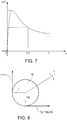
- the force F a (t) acts on the contact point between the wheel and the rail ( figure 8 ).
- the adhesion coefficient ⁇ varies as a function of the sliding ⁇ substantially in the way illustrated in the graph of figure 7 .
- pseudostatic ( ⁇ ⁇ 0) ⁇ values such as to allow the slipping phenomena to start, are near to 0.09 and can drop to values around 0.01 or even less in the presence of wet leaves or mixtures of water and rust on the rails, i.e. undergoing variations on the order of 20 dB.
- the instantaneous value of ⁇ ( ⁇ ) at the variation in real time of ⁇ may undergo variations up to -6 dB, or higher.
- the mass m on the axle may vary between the tare weight and the full load weight, both statically and dynamically during slipping, due to the pitching of the carriage, with consequent redistribution of the weight between the two axles of the carriage.
- a system intended to manage a torque control by means of a plurality of actuators must adapt to different transfer functions and different time constants, in real time.
- the coexistence of these changes requires the implementation of a "non-rigid" tuning, such as to accept the entire spectrum of variations, with the consequence of not obtaining an accurate and responsive control to rapid environmental variations, or an adaptive tuning "mapped" through a "look-up table" of parameters selected in real-time as a function of one or more of the environmental variables, such as described in EP 2 147 840 A2 .
- EP 2 147 840 A1 describes a method for the control and the possible recovery of adhesion of the wheels of a controlled axle of a railway vehicle.
- Such a method comprises the generation of a first speed signal indicative of the actual angular speed of the wheels of said axle and of a second speed signal indicative of the actual vehicle speed. From these speed signals the value of the actual instantaneous sliding of the axle's wheels is calculated. The error or difference between the value of the actual instantaneous sliding and a desired sliding value is calculated as a function of the detected acceleration of the axle's wheels and the brake pressure imparted to the brake cylinders associated with these wheels. This sliding error or difference is used to generate a driving signal for the control means of the braking pressure.
- This driving signal is generated with the use of a PID-type control device, the parameters of which are modified as a function of the detected speed of the vehicle, these parameters being able to assume a plurality of respective predetermined discrete values for different ranges of vehicle speed values.
- an object of the present invention is to provide an improved method for controlling and possibly recovering the adhesion of the wheels of a controlled axle of a railway vehicle, making it possible in particular to correct in a continuous manner, in real time, the control parameters, allowing an adaptation to the instantaneous values of adhesion and weight of the vehicle.
- the aforementioned input signal is a signal representative of the set point speed for the axle's wheels.
- said input signal is a signal representative of the aforementioned error or difference in speed.
- the method according to the present invention applies adaptive-type techniques to the tuning and the dynamic correction of the control parameters of the slipping of the wheels of an axle, such techniques being performed continuously over time, in real time and not based on vectors or parametric tables mapped previously.
- the invention for this object, uses a control technique based on adaptive filtering, as described for example in B. Widrow and S.D. Stearns, Adaptive Signal Processing, New Jersey, Prentice-Hall, Inc., 1985 .
- adaptive filters suitable for use in a method according to the invention.
- the present invention provides the use of adaptive filters known as LMS (Least Mean Square) filters.
- LMS Least Mean Square
- the adaptive filters used may consist of both FIR-type (Finite Impulse Response) structures, and IIR-type (Infinite Impulse Response) structures.
- X(t) and Y(t) shall designate the input and output of such a filter.
- time variable t will be denoted by the letter T to indicate that such time is understood in a discrete sense, namely that the method/system operates for finite samples with a period T.
- Figure 4 shows a first control system schematically illustrated for implementing the method according to the present invention.
- the system according to figure 4 comprises a block RM that represents a reference model that receives as input the set point speed V SETPOINT for the wheels W of the controlled axle A and which provides at its output the speed V R (t) of the axle A in response to the set point speed and its variations.
- G a more meaningful system, i.e. one adhering more to reality, for example (but not exclusively) a second order transfer function, approximating the expected model of the complex formed by the control module CM of the torque control apparatus TC and by the wheels W of figure 2 .
- AF indicates an adaptive filter, for example an LMS-type filter.
- a signal is supplied which is a function of the speed V SETPOINT , for example, a signal proportional to the vehicle speed, typically between 65% and 95% of the vehicle's speed.
- the output Y(T) of the adaptive filter AF is a signal for driving the torque control apparatus TC, which is in turn coupled to the axle A and its wheels W.
- the output V R (T) of the block RM is applied to an input of an adder ADD, to another input from which arrives a signal V M (T) indicative of the angular speed of the axle A actually measured by means of an SS detector and an associated acquisition and processing module APM.
- the adder ADD provides as its output an error signal E(T) indicative of the error or difference between the speed V R (T) and the measured speed V M (T), i.e. the difference between the expected speed at the output of the RM block and the speed V M (T).
- the error signal E(T) is fed to the adaptive filter AF, where it is used to implement a continuous correction of the parameters of this filter, as long as this error E(T) tends to zero.
- the stabilization of the coefficients or parameters of the adaptive filter AF can happen quickly if the input signal X(T) has a harmonic content equivalent to the bandwidth of the process to be controlled.
- the speed V SETPOINT is a signal with a practically null harmonic content and thus relatively unsatisfactory as regards the need for a rapid retuning of the parameters or coefficients of the filter AF.
- Such a solution may still be effectively used by initializing the coefficients of the filter AF to standard values, pre-calculated on the basis of an initial situation of compromise and subsequently, in the course of a slip phenomenon, the variations of the error E(T) at the input of the filter AF are sufficient to implement in real-time a proper correction of the coefficients or parameters of the filter.
- the error E(T) has an appropriate harmonic content for self-calibration of the filter AF and at the same time contains the information necessary for the generation of the corrections of the braking force acting on the controlled axle A.
- the solution according to figure 5 allows a very fast dynamic calibration of the coefficients or parameters of the adaptive filter AF, even if initially these coefficients or parameters were completely zeroed.
- the LMS-type adaptive filters can be realized both by using FIR structures and IIR structures.
- the FIR structures are inherently stable, having no memory. However, this feature prevents the implementation of control functions having an integrative component, unless one uses the existing natural integrators downstream in the system, for example the natural integration represented by the braking cylinder.
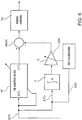
- Figure 6 illustrates an embodiment which allows one to overcome the lack of an integrative component in a LMS-type adaptive filter AF produced by an FIR structure.
- An integrator I is provided substantially in parallel to this adaptive filter AF, between the input of this filter and an adder ADD1, which receives the output of the filter AF and the output of the integrator I; the output of the adder ADD1 is connected to the torque control apparatus TC.
- a self-tuning apparatus STA may optionally be associated with the integrator I and it includes a dedicated LMS-type cell C, connected between the output of the integrator I and the adder ADD1 and driven as a function of the error signal E(T).
- the leakage function characteristic of adaptive filters is appropriately used, to perform a continuous de-tuning of the coefficients or parameters of the filter when the error E(T) is close to zero, or in any case within the limits of variation of the coefficients or parameters such as to permit the recovery of a correct tuning of these coefficients or parameters as soon as they re-present significant E(T) values.
- an adaptive filter made with an IIR-type structure which may take a PID-type (Proportional-Integrative-Derivative) configuration.
Landscapes
- Engineering & Computer Science (AREA)
- Transportation (AREA)
- Mechanical Engineering (AREA)
- Life Sciences & Earth Sciences (AREA)
- Sustainable Development (AREA)
- Sustainable Energy (AREA)
- Power Engineering (AREA)
- Electromagnetism (AREA)
- Physics & Mathematics (AREA)
- General Physics & Mathematics (AREA)
- Radar, Positioning & Navigation (AREA)
- Automation & Control Theory (AREA)
- Electric Propulsion And Braking For Vehicles (AREA)
- Regulating Braking Force (AREA)
- Hydraulic Clutches, Magnetic Clutches, Fluid Clutches, And Fluid Joints (AREA)
- Vehicle Body Suspensions (AREA)
Claims (9)
- Verfahren zum Steuern bzw. Regeln und möglicherweise Wiederherstellen der Haftung der Räder (W) einer gesteuerten bzw. geregelten Achse (A) eines Schienenfahrzeugs, umfassend die Schritte:Erzeugen von Geschwindigkeitssignalen (VM), welche die Winkelgeschwindigkeit der Räder (W) der Achse (A) angeben;gekennzeichnet durchErzeugen eines Fehlersignals (E), das den Fehler oder die Differenz zwischen einer mittels eines Referenzmodells (RM) bestimmten Referenzgeschwindigkeit (VR) für die Räder (W) als Antwort auf eine zugewiesene Sollgeschwindigkeit (VSETPOINT) und die durch die Geschwindigkeitssignale (VM) angegebene Geschwindigkeit angibt; undErzeugen eines Ansteuersignals (Y) für Drehmomentsteuer- bzw. -regelmittel (TC), die an die Räder (W) der Achse (A) angelegt werden, durch adaptives Filtern (AF) eines Eingangssignals (X), das eine Funktion der Sollgeschwindigkeit (VSETPOINT) ist, Modifizieren von Parametern der adaptiven Filterung (AF) als eine Funktion des Fehlersignals (E), so dass der Geschwindigkeitsfehler oder die Differenz (E) gegen Null tendieren.
- Verfahren nach Anspruch 1, wobei das Eingangssignal (X) ein Signal ist, das die Sollgeschwindigkeit (VSETPOINT) darstellt.
- Verfahren nach Anspruch 1, wobei das Eingangssignal (X) ein Signal (E) ist, das den Geschwindigkeitsfehler oder die Geschwindigkeitsdifferenz darstellt.
- Verfahren nach einem der vorhergehenden Ansprüche, wobei das Ansteuersignal (Y) mittels eines adaptiven Filters (AF) mit FIR-Typ-Struktur mit einem Parallelintegrator (I) erzeugt wird.
- Verfahren nach Anspruch 3, wobei das vom Integrator (I) bereitgestellte Signal einer adaptiven Kalibrierung unterzogen wird.
- Verfahren nach einem der Ansprüche 1 bis 3, wobei das Ansteuersignal (Y) mittels eines adaptiven Filters (AF) mit einer IIR-Typ-Struktur und vorzugsweise einer PID-Typ-Konfiguration erhalten wird.
- Verfahren nach einem der vorhergehenden Ansprüche, wobei Parameter oder Koeffizienten der adaptiven Filterung mit vorberechneten Werten initialisiert werden, die in einem nichtflüchtigen Speicher gespeichert sind.
- Verfahren nach einem der vorhergehenden Ansprüche, wobei die Parameter oder Koeffizienten der adaptiven Filterung in einem vordefinierten Variationsband begrenzt und in einem nichtflüchtigen Speicher gespeichert werden.
- Verfahren nach einem der vorhergehenden Ansprüche, wobei mittels einer Leckagefunktion der adaptiven Filterung die Parameter oder Koeffizienten der Filterung zeitlich kontinuierlich reduziert werden.
Applications Claiming Priority (2)
| Application Number | Priority Date | Filing Date | Title |
|---|---|---|---|
| ITUB2015A009358A ITUB20159358A1 (it) | 2015-12-22 | 2015-12-22 | Procedimento per il controllo e il recupero dell'aderenza delle ruote di un assile controllato di un veicolo ferroviario. |
| PCT/IB2016/057813 WO2017109690A1 (en) | 2015-12-22 | 2016-12-20 | Method for controlling and recovering the adhesion of the wheels of a controlled axle of a railway vehicle |
Publications (2)
| Publication Number | Publication Date |
|---|---|
| EP3393873A1 EP3393873A1 (de) | 2018-10-31 |
| EP3393873B1 true EP3393873B1 (de) | 2019-11-06 |
Family
ID=55697357
Family Applications (1)
| Application Number | Title | Priority Date | Filing Date |
|---|---|---|---|
| EP16834112.1A Active EP3393873B1 (de) | 2015-12-22 | 2016-12-20 | Verfahren für die regelung und die wiederherstellung der adhäsion der räder einer geregelten achse eines schienenfahrzeuges |
Country Status (9)
| Country | Link |
|---|---|
| US (1) | US11772495B2 (de) |
| EP (1) | EP3393873B1 (de) |
| JP (1) | JP7125346B2 (de) |
| CN (1) | CN108602504B (de) |
| ES (1) | ES2760123T3 (de) |
| HU (1) | HUE047241T2 (de) |
| IT (1) | ITUB20159358A1 (de) |
| RU (1) | RU2725019C2 (de) |
| WO (1) | WO2017109690A1 (de) |
Cited By (3)
| Publication number | Priority date | Publication date | Assignee | Title |
|---|---|---|---|---|
| EP4301641A1 (de) * | 2021-03-02 | 2024-01-10 | Faiveley Transport Italia S.p.A. | Gleitschutzsystem für ein elektromechanisches bremssystem |
| US11904827B2 (en) | 2019-04-30 | 2024-02-20 | Faiveley Transport Italia S.P.A. | Rotational monitoring system of at least one axle for a railway vehicle or train |
| US12214762B2 (en) | 2019-03-08 | 2025-02-04 | Faiveley Transport Italia S.P.A. | Supervising device for monitoring the operation of an anti-slip device of a railway braking system |
Families Citing this family (8)
| Publication number | Priority date | Publication date | Assignee | Title |
|---|---|---|---|---|
| US12509834B2 (en) | 2017-06-12 | 2025-12-30 | Faiveley Transport Italia, S.P.A. | Route cleaning system |
| IT201700064371A1 (it) * | 2017-06-12 | 2018-12-12 | Faiveley Transport Italia Spa | Procedimento per la valutazione della contaminazione di una rotaia, particolarmente per un veicolo ferroviario. |
| IT201700102369A1 (it) | 2017-09-13 | 2019-03-13 | Faiveley Transport Italia Spa | Sistema per il controllo di frenatura di servizio e di emergenza per almeno un veicolo ferroviario. |
| ES2911573T3 (es) * | 2017-12-18 | 2022-05-19 | Faiveley Transport Italia Spa | Sistema de control de frenado de emergencia y de servicio para al menos un vehículo ferroviario |
| IT201800010349A1 (it) | 2018-11-15 | 2020-05-15 | Faiveley Transport Italia Spa | Sistema di controllo elettronico della frenatura di un veicolo ferroviario |
| IT202100000428A1 (it) * | 2021-01-12 | 2022-07-12 | Faiveley Transport Italia Spa | Procedimento di calibrazione di una catena di acquisizione di un dispositivo o sistema di frenatura di almeno un veicolo ferroviario |
| IT202100031565A1 (it) * | 2021-12-16 | 2023-06-16 | Faiveley Transport Italia Spa | Attuatore elettromeccanico per un sistema di frenatura di un veicolo, sistema di frenatura e veicolo |
| ES2989275T3 (es) * | 2022-07-04 | 2024-11-25 | Dellner Bubenzer Ab | Controlador para estimar los pesos individuales de los ejes de un vehículo ferroviario, procedimiento implementado por ordenador para este, programa informático y portadora de datos no volátil |
Family Cites Families (45)
| Publication number | Priority date | Publication date | Assignee | Title |
|---|---|---|---|---|
| FR2523913A1 (fr) * | 1982-03-24 | 1983-09-30 | Faiveley Ets | Procede pour la detection et la correction du patinage des roues d'un engin moteur de chemin de fer et dispositif pour sa mise en oeuvre |
| JPS6091805A (ja) * | 1983-10-21 | 1985-05-23 | Hitachi Ltd | 鉄道車両制御装置 |
| US4990840A (en) * | 1988-02-19 | 1991-02-05 | The Cross Company | Method and system for controlling a machine tool such as a turning machine |
| US4818037A (en) * | 1988-05-16 | 1989-04-04 | Hughes Aircraft Company | Method for estimating reference speed and acceleration for traction and anti-skid braking control |
| DE3902846A1 (de) * | 1989-01-27 | 1990-08-02 | Licentia Gmbh | Verfahren und anordnung zur regelung der antriebs- und/oder bremskraft der fahrmotoren eines laufachsenlosen triebfahrzeuges an der kraftschlussgrenze der raeder |
| EP0440365B1 (de) * | 1990-01-25 | 1995-06-21 | Mitsubishi Jidosha Kogyo Kabushiki Kaisha | Verfahren und Vorrichtung zum Feststellen des Lenkausschlagnullpunktes eines Fahrzeuges |
| JP2504307B2 (ja) * | 1990-08-01 | 1996-06-05 | 三菱電機株式会社 | 電動機の速度制御装置 |
| US5334983A (en) * | 1991-09-24 | 1994-08-02 | Toyota Jidosha Kabushiki Kaisha | Doppler-effect ground speed sensor for use with a brake system |
| DE4224581C1 (de) * | 1992-07-22 | 1993-12-02 | Aeg Westinghouse Transport | Verfahren zur Regelung der Antriebs- und/oder Bremskraft der Fahrmotoren eines Triebfahrzeuges an der Kraftschlußgrenze der Räder |
| JP3940056B2 (ja) * | 2002-10-11 | 2007-07-04 | アイシン精機株式会社 | 路面状態推定装置、及び該装置を備えた車両の運動制御装置 |
| WO2004045933A2 (en) * | 2002-11-18 | 2004-06-03 | Nsk Ltd. | Axle unit with slip sensor and slip measurement method |
| US7317978B2 (en) * | 2003-09-05 | 2008-01-08 | Nissan Motor Co., Ltd. | Driving force control apparatus for vehicle |
| US7027900B2 (en) * | 2003-09-19 | 2006-04-11 | General Electric Company | Enhanced locomotive adhesion control |
| US7064507B2 (en) * | 2004-02-17 | 2006-06-20 | Railpower Technologies Corp. | Managing wheel skid in a locomotive |
| DE102004036565B4 (de) * | 2004-07-28 | 2008-12-18 | Robert Bosch Gmbh | Vorrichtung und Verfahren zum Stabilisieren eines Fahrzeugs |
| AT503060A1 (de) * | 2005-04-28 | 2007-07-15 | Siemens Transportation Systems | Adaptiver gleitschutz für schienenfahrzeuge |
| US7285926B2 (en) * | 2005-06-30 | 2007-10-23 | General Electric Company | System and method for locomotive adhesion control |
| JP4174061B2 (ja) * | 2006-03-23 | 2008-10-29 | 本田技研工業株式会社 | ハイブリッド車両の能動型制振制御装置 |
| JP4717716B2 (ja) * | 2006-05-25 | 2011-07-06 | 株式会社ブリヂストン | 路面状態推定装置及び方法 |
| CN100410114C (zh) * | 2006-08-31 | 2008-08-13 | 株洲南车时代电气股份有限公司 | 一种列车防滑控制方法及装置 |
| JP4340676B2 (ja) * | 2006-10-11 | 2009-10-07 | 本田技研工業株式会社 | 制御装置 |
| DE102006057342A1 (de) * | 2006-12-05 | 2008-06-12 | Siemens Ag | Verfahren zum Ermitteln eines Fahrbahnzustands |
| ATE528185T1 (de) * | 2007-03-01 | 2011-10-15 | Haldex Brake Prod Ab | SYSTEME UND VERFAHREN ZUR BESTIMMUNG EINES PARAMETERS IN ZUSAMMENHANG MIT DEM KONTAKT ZWISCHEN REIFEN UND STRAßE UND/ODER DEM VERHÄLTNIS ZWISCHEN EINEM RAD UND EINER FAHRZEUGBEWEGUNG |
| EP1986466B1 (de) * | 2007-04-25 | 2018-08-08 | Harman Becker Automotive Systems GmbH | Verfahren und Vorrichtung zur Klangabstimmung |
| JP5063274B2 (ja) * | 2007-09-21 | 2012-10-31 | 東洋電機製造株式会社 | 電気車制御装置 |
| JP4430100B2 (ja) * | 2007-12-25 | 2010-03-10 | 本田技研工業株式会社 | 制御装置 |
| US8645011B2 (en) * | 2008-02-15 | 2014-02-04 | Schaffler Ip Pty Limited | Traction control system and method |
| DE102008034657A1 (de) * | 2008-07-25 | 2010-02-04 | Knorr-Bremse Systeme für Schienenfahrzeuge GmbH | Verfahren und Einrichtung zur adaptiven Ansteuerung der Gleitschutzregelung einer pneumatischen Bremsanlage eines Schienenfahrzeuges |
| DE102008063891A1 (de) * | 2008-12-19 | 2010-07-01 | Knorr-Bremse Systeme für Schienenfahrzeuge GmbH | Bremsanlage eines Schienenfahrzeugs reduziertem Stick-Slip-Effekt |
| DE102009012128B4 (de) * | 2009-03-06 | 2019-09-05 | Volkswagen Ag | Verfahren zum Bestimmen einer Rauigkeit einer Fahrbahnoberfläche für ein Fahrzeug |
| EP2394876B1 (de) * | 2009-03-30 | 2014-10-15 | Honda Motor Co., Ltd. | Vorrichtung zur messung der statusquantität von rutschbewegungen eines fahrzeugs |
| US8197016B2 (en) * | 2009-05-01 | 2012-06-12 | Goodrich Corporation | Brake fill effect minimization function |
| GB2486177A (en) * | 2010-12-02 | 2012-06-13 | Land Rover Uk Ltd | Traction control method that allows for processing time delays |
| JP5634893B2 (ja) * | 2011-01-21 | 2014-12-03 | 本田技研工業株式会社 | 能動型振動騒音制御装置 |
| KR20120099840A (ko) * | 2011-03-02 | 2012-09-12 | 삼성전자주식회사 | 서보 컨트롤러 및 이를 포함하는 서보 시스템 |
| US8838357B2 (en) * | 2011-06-03 | 2014-09-16 | Toyota Jidosha Kabushiki Kaisha | Braking force distribution control device for a vehicle |
| DE102011110053A1 (de) * | 2011-08-12 | 2013-02-14 | Knorr-Bremse Systeme für Schienenfahrzeuge GmbH | Bremsanlage mit Magnetschienenbremseinrichtung |
| EP2786907B1 (de) * | 2011-11-30 | 2020-01-08 | Advics Co., Ltd | Bremssteuervorrichtung für ein fahrzeug |
| DE102011089653A1 (de) * | 2011-12-22 | 2013-06-27 | Siemens Aktiengesellschaft | Verfahren und Anordnung zum Überwachen eines Bremssystems einer Bremsanordnung eines Schienenfahrzeugs |
| DE102012200139A1 (de) * | 2012-01-05 | 2013-07-11 | Robert Bosch Gmbh | Verfahren und Vorrichtung zur radunabhängigen Geschwindigkeitsmessung bei einem Fahrzeug |
| CN103738351B (zh) * | 2013-12-18 | 2016-04-20 | 北京交控科技股份有限公司 | 一种应对恶劣天气的列车控制方法 |
| US9463873B2 (en) * | 2014-07-13 | 2016-10-11 | The Boeing Company | Vehicle braking system having braking control and skid reduction functions |
| GB2534571B (en) * | 2015-01-27 | 2018-06-13 | Jaguar Land Rover Ltd | Vehicle speed control having constraining drive torque in dependence on a target speed and the mean speed of the driven wheels |
| RU156444U1 (ru) * | 2015-03-18 | 2015-11-10 | Федеральное государственное бюджетное образовательное учреждение высшего профессионального образования "Брянский государственный технический университет" | Устройство для предотвращения буксования локомотива |
| US9988026B2 (en) * | 2015-12-22 | 2018-06-05 | Autoliv-Nissin Brake Systems Japan Co., Ltd. | System and method for independently controlling wheel slip and vehicle acceleration |
-
2015
- 2015-12-22 IT ITUB2015A009358A patent/ITUB20159358A1/it unknown
-
2016
- 2016-12-20 HU HUE16834112A patent/HUE047241T2/hu unknown
- 2016-12-20 US US16/064,245 patent/US11772495B2/en active Active
- 2016-12-20 RU RU2018126797A patent/RU2725019C2/ru active
- 2016-12-20 ES ES16834112T patent/ES2760123T3/es active Active
- 2016-12-20 CN CN201680075346.5A patent/CN108602504B/zh active Active
- 2016-12-20 WO PCT/IB2016/057813 patent/WO2017109690A1/en not_active Ceased
- 2016-12-20 JP JP2018532208A patent/JP7125346B2/ja active Active
- 2016-12-20 EP EP16834112.1A patent/EP3393873B1/de active Active
Non-Patent Citations (1)
| Title |
|---|
| None * |
Cited By (5)
| Publication number | Priority date | Publication date | Assignee | Title |
|---|---|---|---|---|
| US12214762B2 (en) | 2019-03-08 | 2025-02-04 | Faiveley Transport Italia S.P.A. | Supervising device for monitoring the operation of an anti-slip device of a railway braking system |
| US11904827B2 (en) | 2019-04-30 | 2024-02-20 | Faiveley Transport Italia S.P.A. | Rotational monitoring system of at least one axle for a railway vehicle or train |
| EP4301641A1 (de) * | 2021-03-02 | 2024-01-10 | Faiveley Transport Italia S.p.A. | Gleitschutzsystem für ein elektromechanisches bremssystem |
| EP4301641B1 (de) * | 2021-03-02 | 2025-07-30 | Faiveley Transport Italia S.p.A. | Gleitschutzsystem für ein elektromechanisches bremssystem |
| US12503090B2 (en) | 2021-03-02 | 2025-12-23 | Faiveley Transport Italia S.P.A. | Anti-skid system for an electromechanical braking system |
Also Published As
| Publication number | Publication date |
|---|---|
| JP7125346B2 (ja) | 2022-08-24 |
| ES2760123T3 (es) | 2020-05-13 |
| CN108602504A (zh) | 2018-09-28 |
| ITUB20159358A1 (it) | 2017-06-22 |
| RU2725019C2 (ru) | 2020-06-29 |
| JP2019507567A (ja) | 2019-03-14 |
| HUE047241T2 (hu) | 2020-04-28 |
| US20190001822A1 (en) | 2019-01-03 |
| US11772495B2 (en) | 2023-10-03 |
| CN108602504B (zh) | 2020-12-18 |
| EP3393873A1 (de) | 2018-10-31 |
| RU2018126797A (ru) | 2020-01-23 |
| RU2018126797A3 (de) | 2020-04-28 |
| WO2017109690A1 (en) | 2017-06-29 |
Similar Documents
| Publication | Publication Date | Title |
|---|---|---|
| EP3393873B1 (de) | Verfahren für die regelung und die wiederherstellung der adhäsion der räder einer geregelten achse eines schienenfahrzeuges | |
| CN109070855B (zh) | 用于控制和可能地恢复轨道车辆的受控轮轴的车轮的附着力的方法 | |
| Jiang et al. | An application of nonlinear PID control to a class of truck ABS problems | |
| CA2975066C (en) | Control device for electric motor vehicle and control method for electric motor vehicle | |
| CA3021274C (en) | Control method for electric vehicle and control device for electric vehicle | |
| Kawabe et al. | A sliding mode controller for wheel slip ratio control system | |
| US6453226B1 (en) | Integrated control of active tire steer and brakes | |
| CA2975061C (en) | Control device for electric motor vehicle and control method for electric motor vehicle | |
| RU2381927C2 (ru) | Адаптивная защита от проскальзывания для рельсовых транспортных средств с регулятором проскальзывания | |
| Johansen et al. | Hybrid control strategies in ABS | |
| CN108136905A (zh) | 在机动车中的行驶动力学调节系统和用于行驶动力学调节系统的电子的行驶动力学控制单元 | |
| CA2987032A1 (en) | Control device for electric vehicle and control method for electric vehicle | |
| US20220258617A1 (en) | Electric vehicle control method and electric vehicle control device | |
| US5782541A (en) | Pressure control process and apparatus | |
| CA2642267A1 (en) | Vehicle control device | |
| EP0936116B1 (de) | Bremssteuerungssysteme und Verfahren | |
| WO2018043519A1 (ja) | ブレーキシステム、車両および隊列走行車両群 | |
| CN109070916B (zh) | 用于计算轨道车辆的前进速度的方法 | |
| CN108025712B (zh) | 用来运行用于具有制动系统的轨道车辆的制动控制系统的方法、制动控制系统、制动系统以及轨道车辆 | |
| US20200369305A1 (en) | Vehicle control system | |
| JPH01275251A (ja) | アンチスキッド制御装置 | |
| JP2012039738A (ja) | 自動列車運転装置 | |
| JP6880674B2 (ja) | 電動車両の制御方法、及び、電動車両の制御装置 | |
| US20240424912A1 (en) | Electric vehicle control method and electric vehicle control device | |
| Khansari et al. | Independent model generalized predictive controller design for antilock braking system |
Legal Events
| Date | Code | Title | Description |
|---|---|---|---|
| STAA | Information on the status of an ep patent application or granted ep patent |
Free format text: STATUS: UNKNOWN |
|
| STAA | Information on the status of an ep patent application or granted ep patent |
Free format text: STATUS: THE INTERNATIONAL PUBLICATION HAS BEEN MADE |
|
| PUAI | Public reference made under article 153(3) epc to a published international application that has entered the european phase |
Free format text: ORIGINAL CODE: 0009012 |
|
| STAA | Information on the status of an ep patent application or granted ep patent |
Free format text: STATUS: REQUEST FOR EXAMINATION WAS MADE |
|
| 17P | Request for examination filed |
Effective date: 20180709 |
|
| AK | Designated contracting states |
Kind code of ref document: A1 Designated state(s): AL AT BE BG CH CY CZ DE DK EE ES FI FR GB GR HR HU IE IS IT LI LT LU LV MC MK MT NL NO PL PT RO RS SE SI SK SM TR |
|
| AX | Request for extension of the european patent |
Extension state: BA ME |
|
| DAV | Request for validation of the european patent (deleted) | ||
| DAX | Request for extension of the european patent (deleted) | ||
| GRAP | Despatch of communication of intention to grant a patent |
Free format text: ORIGINAL CODE: EPIDOSNIGR1 |
|
| STAA | Information on the status of an ep patent application or granted ep patent |
Free format text: STATUS: GRANT OF PATENT IS INTENDED |
|
| INTG | Intention to grant announced |
Effective date: 20190521 |
|
| GRAS | Grant fee paid |
Free format text: ORIGINAL CODE: EPIDOSNIGR3 |
|
| GRAA | (expected) grant |
Free format text: ORIGINAL CODE: 0009210 |
|
| STAA | Information on the status of an ep patent application or granted ep patent |
Free format text: STATUS: THE PATENT HAS BEEN GRANTED |
|
| AK | Designated contracting states |
Kind code of ref document: B1 Designated state(s): AL AT BE BG CH CY CZ DE DK EE ES FI FR GB GR HR HU IE IS IT LI LT LU LV MC MK MT NL NO PL PT RO RS SE SI SK SM TR |
|
| REG | Reference to a national code |
Ref country code: GB Ref legal event code: FG4D |
|
| REG | Reference to a national code |
Ref country code: CH Ref legal event code: EP Ref country code: AT Ref legal event code: REF Ref document number: 1198349 Country of ref document: AT Kind code of ref document: T Effective date: 20191115 |
|
| REG | Reference to a national code |
Ref country code: DE Ref legal event code: R096 Ref document number: 602016024029 Country of ref document: DE |
|
| REG | Reference to a national code |
Ref country code: IE Ref legal event code: FG4D |
|
| REG | Reference to a national code |
Ref country code: NL Ref legal event code: MP Effective date: 20191106 |
|
| REG | Reference to a national code |
Ref country code: LT Ref legal event code: MG4D |
|
| REG | Reference to a national code |
Ref country code: HU Ref legal event code: AG4A Ref document number: E047241 Country of ref document: HU |
|
| PG25 | Lapsed in a contracting state [announced via postgrant information from national office to epo] |
Ref country code: LV Free format text: LAPSE BECAUSE OF FAILURE TO SUBMIT A TRANSLATION OF THE DESCRIPTION OR TO PAY THE FEE WITHIN THE PRESCRIBED TIME-LIMIT Effective date: 20191106 Ref country code: PL Free format text: LAPSE BECAUSE OF FAILURE TO SUBMIT A TRANSLATION OF THE DESCRIPTION OR TO PAY THE FEE WITHIN THE PRESCRIBED TIME-LIMIT Effective date: 20191106 Ref country code: NO Free format text: LAPSE BECAUSE OF FAILURE TO SUBMIT A TRANSLATION OF THE DESCRIPTION OR TO PAY THE FEE WITHIN THE PRESCRIBED TIME-LIMIT Effective date: 20200206 Ref country code: PT Free format text: LAPSE BECAUSE OF FAILURE TO SUBMIT A TRANSLATION OF THE DESCRIPTION OR TO PAY THE FEE WITHIN THE PRESCRIBED TIME-LIMIT Effective date: 20200306 Ref country code: BG Free format text: LAPSE BECAUSE OF FAILURE TO SUBMIT A TRANSLATION OF THE DESCRIPTION OR TO PAY THE FEE WITHIN THE PRESCRIBED TIME-LIMIT Effective date: 20200206 Ref country code: SE Free format text: LAPSE BECAUSE OF FAILURE TO SUBMIT A TRANSLATION OF THE DESCRIPTION OR TO PAY THE FEE WITHIN THE PRESCRIBED TIME-LIMIT Effective date: 20191106 Ref country code: FI Free format text: LAPSE BECAUSE OF FAILURE TO SUBMIT A TRANSLATION OF THE DESCRIPTION OR TO PAY THE FEE WITHIN THE PRESCRIBED TIME-LIMIT Effective date: 20191106 Ref country code: GR Free format text: LAPSE BECAUSE OF FAILURE TO SUBMIT A TRANSLATION OF THE DESCRIPTION OR TO PAY THE FEE WITHIN THE PRESCRIBED TIME-LIMIT Effective date: 20200207 Ref country code: LT Free format text: LAPSE BECAUSE OF FAILURE TO SUBMIT A TRANSLATION OF THE DESCRIPTION OR TO PAY THE FEE WITHIN THE PRESCRIBED TIME-LIMIT Effective date: 20191106 Ref country code: NL Free format text: LAPSE BECAUSE OF FAILURE TO SUBMIT A TRANSLATION OF THE DESCRIPTION OR TO PAY THE FEE WITHIN THE PRESCRIBED TIME-LIMIT Effective date: 20191106 |
|
| REG | Reference to a national code |
Ref country code: ES Ref legal event code: FG2A Ref document number: 2760123 Country of ref document: ES Kind code of ref document: T3 Effective date: 20200513 |
|
| PG25 | Lapsed in a contracting state [announced via postgrant information from national office to epo] |
Ref country code: RS Free format text: LAPSE BECAUSE OF FAILURE TO SUBMIT A TRANSLATION OF THE DESCRIPTION OR TO PAY THE FEE WITHIN THE PRESCRIBED TIME-LIMIT Effective date: 20191106 Ref country code: HR Free format text: LAPSE BECAUSE OF FAILURE TO SUBMIT A TRANSLATION OF THE DESCRIPTION OR TO PAY THE FEE WITHIN THE PRESCRIBED TIME-LIMIT Effective date: 20191106 Ref country code: IS Free format text: LAPSE BECAUSE OF FAILURE TO SUBMIT A TRANSLATION OF THE DESCRIPTION OR TO PAY THE FEE WITHIN THE PRESCRIBED TIME-LIMIT Effective date: 20200306 |
|
| PG25 | Lapsed in a contracting state [announced via postgrant information from national office to epo] |
Ref country code: AL Free format text: LAPSE BECAUSE OF FAILURE TO SUBMIT A TRANSLATION OF THE DESCRIPTION OR TO PAY THE FEE WITHIN THE PRESCRIBED TIME-LIMIT Effective date: 20191106 |
|
| PG25 | Lapsed in a contracting state [announced via postgrant information from national office to epo] |
Ref country code: CZ Free format text: LAPSE BECAUSE OF FAILURE TO SUBMIT A TRANSLATION OF THE DESCRIPTION OR TO PAY THE FEE WITHIN THE PRESCRIBED TIME-LIMIT Effective date: 20191106 Ref country code: RO Free format text: LAPSE BECAUSE OF FAILURE TO SUBMIT A TRANSLATION OF THE DESCRIPTION OR TO PAY THE FEE WITHIN THE PRESCRIBED TIME-LIMIT Effective date: 20191106 Ref country code: EE Free format text: LAPSE BECAUSE OF FAILURE TO SUBMIT A TRANSLATION OF THE DESCRIPTION OR TO PAY THE FEE WITHIN THE PRESCRIBED TIME-LIMIT Effective date: 20191106 Ref country code: DK Free format text: LAPSE BECAUSE OF FAILURE TO SUBMIT A TRANSLATION OF THE DESCRIPTION OR TO PAY THE FEE WITHIN THE PRESCRIBED TIME-LIMIT Effective date: 20191106 |
|
| REG | Reference to a national code |
Ref country code: CH Ref legal event code: PL |
|
| REG | Reference to a national code |
Ref country code: DE Ref legal event code: R097 Ref document number: 602016024029 Country of ref document: DE |
|
| REG | Reference to a national code |
Ref country code: AT Ref legal event code: MK05 Ref document number: 1198349 Country of ref document: AT Kind code of ref document: T Effective date: 20191106 |
|
| REG | Reference to a national code |
Ref country code: BE Ref legal event code: MM Effective date: 20191231 |
|
| PG25 | Lapsed in a contracting state [announced via postgrant information from national office to epo] |
Ref country code: SK Free format text: LAPSE BECAUSE OF FAILURE TO SUBMIT A TRANSLATION OF THE DESCRIPTION OR TO PAY THE FEE WITHIN THE PRESCRIBED TIME-LIMIT Effective date: 20191106 Ref country code: SM Free format text: LAPSE BECAUSE OF FAILURE TO SUBMIT A TRANSLATION OF THE DESCRIPTION OR TO PAY THE FEE WITHIN THE PRESCRIBED TIME-LIMIT Effective date: 20191106 Ref country code: MC Free format text: LAPSE BECAUSE OF FAILURE TO SUBMIT A TRANSLATION OF THE DESCRIPTION OR TO PAY THE FEE WITHIN THE PRESCRIBED TIME-LIMIT Effective date: 20191106 |
|
| PLBE | No opposition filed within time limit |
Free format text: ORIGINAL CODE: 0009261 |
|
| STAA | Information on the status of an ep patent application or granted ep patent |
Free format text: STATUS: NO OPPOSITION FILED WITHIN TIME LIMIT |
|
| 26N | No opposition filed |
Effective date: 20200807 |
|
| PG25 | Lapsed in a contracting state [announced via postgrant information from national office to epo] |
Ref country code: LU Free format text: LAPSE BECAUSE OF NON-PAYMENT OF DUE FEES Effective date: 20191220 Ref country code: IE Free format text: LAPSE BECAUSE OF NON-PAYMENT OF DUE FEES Effective date: 20191220 |
|
| PG25 | Lapsed in a contracting state [announced via postgrant information from national office to epo] |
Ref country code: CH Free format text: LAPSE BECAUSE OF NON-PAYMENT OF DUE FEES Effective date: 20191231 Ref country code: BE Free format text: LAPSE BECAUSE OF NON-PAYMENT OF DUE FEES Effective date: 20191231 Ref country code: LI Free format text: LAPSE BECAUSE OF NON-PAYMENT OF DUE FEES Effective date: 20191231 Ref country code: AT Free format text: LAPSE BECAUSE OF FAILURE TO SUBMIT A TRANSLATION OF THE DESCRIPTION OR TO PAY THE FEE WITHIN THE PRESCRIBED TIME-LIMIT Effective date: 20191106 Ref country code: SI Free format text: LAPSE BECAUSE OF FAILURE TO SUBMIT A TRANSLATION OF THE DESCRIPTION OR TO PAY THE FEE WITHIN THE PRESCRIBED TIME-LIMIT Effective date: 20191106 |
|
| PG25 | Lapsed in a contracting state [announced via postgrant information from national office to epo] |
Ref country code: CY Free format text: LAPSE BECAUSE OF FAILURE TO SUBMIT A TRANSLATION OF THE DESCRIPTION OR TO PAY THE FEE WITHIN THE PRESCRIBED TIME-LIMIT Effective date: 20191106 |
|
| PG25 | Lapsed in a contracting state [announced via postgrant information from national office to epo] |
Ref country code: MT Free format text: LAPSE BECAUSE OF FAILURE TO SUBMIT A TRANSLATION OF THE DESCRIPTION OR TO PAY THE FEE WITHIN THE PRESCRIBED TIME-LIMIT Effective date: 20191106 |
|
| PG25 | Lapsed in a contracting state [announced via postgrant information from national office to epo] |
Ref country code: TR Free format text: LAPSE BECAUSE OF FAILURE TO SUBMIT A TRANSLATION OF THE DESCRIPTION OR TO PAY THE FEE WITHIN THE PRESCRIBED TIME-LIMIT Effective date: 20191106 |
|
| PG25 | Lapsed in a contracting state [announced via postgrant information from national office to epo] |
Ref country code: MK Free format text: LAPSE BECAUSE OF FAILURE TO SUBMIT A TRANSLATION OF THE DESCRIPTION OR TO PAY THE FEE WITHIN THE PRESCRIBED TIME-LIMIT Effective date: 20191106 |
|
| P01 | Opt-out of the competence of the unified patent court (upc) registered |
Effective date: 20230530 |
|
| PGFP | Annual fee paid to national office [announced via postgrant information from national office to epo] |
Ref country code: DE Payment date: 20251113 Year of fee payment: 10 |
|
| PGFP | Annual fee paid to national office [announced via postgrant information from national office to epo] |
Ref country code: GB Payment date: 20251218 Year of fee payment: 10 |
|
| PGFP | Annual fee paid to national office [announced via postgrant information from national office to epo] |
Ref country code: IT Payment date: 20251113 Year of fee payment: 10 |
|
| PGFP | Annual fee paid to national office [announced via postgrant information from national office to epo] |
Ref country code: HU Payment date: 20251205 Year of fee payment: 10 Ref country code: FR Payment date: 20251219 Year of fee payment: 10 |
|
| PGFP | Annual fee paid to national office [announced via postgrant information from national office to epo] |
Ref country code: ES Payment date: 20260114 Year of fee payment: 10 |