EP3392811B1 - Système et procédé de distribution des données à des appareils électroniques - Google Patents
Système et procédé de distribution des données à des appareils électroniques Download PDFInfo
- Publication number
- EP3392811B1 EP3392811B1 EP17167585.3A EP17167585A EP3392811B1 EP 3392811 B1 EP3392811 B1 EP 3392811B1 EP 17167585 A EP17167585 A EP 17167585A EP 3392811 B1 EP3392811 B1 EP 3392811B1
- Authority
- EP
- European Patent Office
- Prior art keywords
- data
- designed
- unit
- communication unit
- communication
- Prior art date
- Legal status (The legal status is an assumption and is not a legal conclusion. Google has not performed a legal analysis and makes no representation as to the accuracy of the status listed.)
- Active
Links
- 238000000034 method Methods 0.000 title claims description 23
- 238000004891 communication Methods 0.000 claims description 154
- 230000006870 function Effects 0.000 claims description 35
- 230000001681 protective effect Effects 0.000 claims description 29
- 238000012423 maintenance Methods 0.000 claims description 15
- 238000010276 construction Methods 0.000 claims description 11
- 238000005259 measurement Methods 0.000 claims description 6
- 238000009434 installation Methods 0.000 claims description 5
- QVFWZNCVPCJQOP-UHFFFAOYSA-N chloralodol Chemical compound CC(O)(C)CC(C)OC(O)C(Cl)(Cl)Cl QVFWZNCVPCJQOP-UHFFFAOYSA-N 0.000 claims description 2
- 230000004913 activation Effects 0.000 claims 2
- 230000009849 deactivation Effects 0.000 claims 2
- 230000001413 cellular effect Effects 0.000 description 9
- 238000012545 processing Methods 0.000 description 2
- 230000001133 acceleration Effects 0.000 description 1
- 238000013459 approach Methods 0.000 description 1
- 230000001276 controlling effect Effects 0.000 description 1
- 230000001419 dependent effect Effects 0.000 description 1
- 239000011521 glass Substances 0.000 description 1
- 238000002372 labelling Methods 0.000 description 1
- 230000004807 localization Effects 0.000 description 1
- 230000003287 optical effect Effects 0.000 description 1
- 230000001105 regulatory effect Effects 0.000 description 1
- 239000004065 semiconductor Substances 0.000 description 1
- 230000003068 static effect Effects 0.000 description 1
Images


Classifications
-
- G—PHYSICS
- G05—CONTROLLING; REGULATING
- G05B—CONTROL OR REGULATING SYSTEMS IN GENERAL; FUNCTIONAL ELEMENTS OF SUCH SYSTEMS; MONITORING OR TESTING ARRANGEMENTS FOR SUCH SYSTEMS OR ELEMENTS
- G05B23/00—Testing or monitoring of control systems or parts thereof
- G05B23/02—Electric testing or monitoring
- G05B23/0205—Electric testing or monitoring by means of a monitoring system capable of detecting and responding to faults
- G05B23/0259—Electric testing or monitoring by means of a monitoring system capable of detecting and responding to faults characterized by the response to fault detection
- G05B23/0283—Predictive maintenance, e.g. involving the monitoring of a system and, based on the monitoring results, taking decisions on the maintenance schedule of the monitored system; Estimating remaining useful life [RUL]
-
- G—PHYSICS
- G06—COMPUTING; CALCULATING OR COUNTING
- G06Q—INFORMATION AND COMMUNICATION TECHNOLOGY [ICT] SPECIALLY ADAPTED FOR ADMINISTRATIVE, COMMERCIAL, FINANCIAL, MANAGERIAL OR SUPERVISORY PURPOSES; SYSTEMS OR METHODS SPECIALLY ADAPTED FOR ADMINISTRATIVE, COMMERCIAL, FINANCIAL, MANAGERIAL OR SUPERVISORY PURPOSES, NOT OTHERWISE PROVIDED FOR
- G06Q30/00—Commerce
- G06Q30/06—Buying, selling or leasing transactions
- G06Q30/0645—Rental transactions; Leasing transactions
-
- G—PHYSICS
- G05—CONTROLLING; REGULATING
- G05B—CONTROL OR REGULATING SYSTEMS IN GENERAL; FUNCTIONAL ELEMENTS OF SUCH SYSTEMS; MONITORING OR TESTING ARRANGEMENTS FOR SUCH SYSTEMS OR ELEMENTS
- G05B23/00—Testing or monitoring of control systems or parts thereof
- G05B23/02—Electric testing or monitoring
- G05B23/0205—Electric testing or monitoring by means of a monitoring system capable of detecting and responding to faults
- G05B23/0208—Electric testing or monitoring by means of a monitoring system capable of detecting and responding to faults characterized by the configuration of the monitoring system
- G05B23/0216—Human interface functionality, e.g. monitoring system providing help to the user in the selection of tests or in its configuration
-
- G—PHYSICS
- G05—CONTROLLING; REGULATING
- G05B—CONTROL OR REGULATING SYSTEMS IN GENERAL; FUNCTIONAL ELEMENTS OF SUCH SYSTEMS; MONITORING OR TESTING ARRANGEMENTS FOR SUCH SYSTEMS OR ELEMENTS
- G05B23/00—Testing or monitoring of control systems or parts thereof
- G05B23/02—Electric testing or monitoring
- G05B23/0205—Electric testing or monitoring by means of a monitoring system capable of detecting and responding to faults
- G05B23/0259—Electric testing or monitoring by means of a monitoring system capable of detecting and responding to faults characterized by the response to fault detection
- G05B23/0275—Fault isolation and identification, e.g. classify fault; estimate cause or root of failure
- G05B23/0281—Quantitative, e.g. mathematical distance; Clustering; Neural networks; Statistical analysis
-
- G—PHYSICS
- G06—COMPUTING; CALCULATING OR COUNTING
- G06F—ELECTRIC DIGITAL DATA PROCESSING
- G06F21/00—Security arrangements for protecting computers, components thereof, programs or data against unauthorised activity
- G06F21/10—Protecting distributed programs or content, e.g. vending or licensing of copyrighted material ; Digital rights management [DRM]
-
- G—PHYSICS
- G06—COMPUTING; CALCULATING OR COUNTING
- G06K—GRAPHICAL DATA READING; PRESENTATION OF DATA; RECORD CARRIERS; HANDLING RECORD CARRIERS
- G06K17/00—Methods or arrangements for effecting co-operative working between equipments covered by two or more of main groups G06K1/00 - G06K15/00, e.g. automatic card files incorporating conveying and reading operations
- G06K17/0022—Methods or arrangements for effecting co-operative working between equipments covered by two or more of main groups G06K1/00 - G06K15/00, e.g. automatic card files incorporating conveying and reading operations arrangements or provisious for transferring data to distant stations, e.g. from a sensing device
-
- G—PHYSICS
- G06—COMPUTING; CALCULATING OR COUNTING
- G06Q—INFORMATION AND COMMUNICATION TECHNOLOGY [ICT] SPECIALLY ADAPTED FOR ADMINISTRATIVE, COMMERCIAL, FINANCIAL, MANAGERIAL OR SUPERVISORY PURPOSES; SYSTEMS OR METHODS SPECIALLY ADAPTED FOR ADMINISTRATIVE, COMMERCIAL, FINANCIAL, MANAGERIAL OR SUPERVISORY PURPOSES, NOT OTHERWISE PROVIDED FOR
- G06Q10/00—Administration; Management
- G06Q10/02—Reservations, e.g. for tickets, services or events
-
- G—PHYSICS
- G06—COMPUTING; CALCULATING OR COUNTING
- G06Q—INFORMATION AND COMMUNICATION TECHNOLOGY [ICT] SPECIALLY ADAPTED FOR ADMINISTRATIVE, COMMERCIAL, FINANCIAL, MANAGERIAL OR SUPERVISORY PURPOSES; SYSTEMS OR METHODS SPECIALLY ADAPTED FOR ADMINISTRATIVE, COMMERCIAL, FINANCIAL, MANAGERIAL OR SUPERVISORY PURPOSES, NOT OTHERWISE PROVIDED FOR
- G06Q10/00—Administration; Management
- G06Q10/20—Administration of product repair or maintenance
-
- H—ELECTRICITY
- H04—ELECTRIC COMMUNICATION TECHNIQUE
- H04W—WIRELESS COMMUNICATION NETWORKS
- H04W4/00—Services specially adapted for wireless communication networks; Facilities therefor
- H04W4/80—Services using short range communication, e.g. near-field communication [NFC], radio-frequency identification [RFID] or low energy communication
-
- G—PHYSICS
- G06—COMPUTING; CALCULATING OR COUNTING
- G06Q—INFORMATION AND COMMUNICATION TECHNOLOGY [ICT] SPECIALLY ADAPTED FOR ADMINISTRATIVE, COMMERCIAL, FINANCIAL, MANAGERIAL OR SUPERVISORY PURPOSES; SYSTEMS OR METHODS SPECIALLY ADAPTED FOR ADMINISTRATIVE, COMMERCIAL, FINANCIAL, MANAGERIAL OR SUPERVISORY PURPOSES, NOT OTHERWISE PROVIDED FOR
- G06Q50/00—Systems or methods specially adapted for specific business sectors, e.g. utilities or tourism
- G06Q50/08—Construction
Definitions
- the present invention relates to a system and method for distributing data for a group of at least two electronic devices, in particular rental devices.
- the rental devices are, in particular, devices that are used in the construction of buildings or other structures, for example in the context of measurement tasks in the field of building installation. This includes devices for optical distance measurement or for the acquisition of three-dimensional coordinates of distant objects such as theodolites, total stations, total stations, laser trackers, laser scanners or handheld distance measuring devices, as well as rotation, sewer or line lasers or cable detectors.
- Cooperating devices can represent, for example, a laser beam projection device and one or more receiver devices for the projected laser beam, such as. B. in the EP 2 741 049 A1 described.
- US 2015/0286209 A1 describes a system consisting of a central computer, one or more mobile devices and one or more electrical tools.
- the system allows the operation of the tools to be monitored and regulated.
- the devices mentioned also have a large number of functions that can be activated or blocked individually, so that the same device can be rented at different prices, depending on which and how many of its functions are to be activated for the respective customer.
- information relevant to the rental agreement such as B. a contract number, a specified return date or the selected configuration, can be displayed on each of the devices in order to make the issue and return of the devices for the lessor, as well as use and return easier for the tenant.
- the landlord it would be advantageous for the landlord if the devices displayed the necessary maintenance dates independently.
- a system or method would therefore be advantageous which allows data to be easily distributed in a group of electronic devices and to display the data thus distributed on the devices for a user.
- So-called smart labels are known from the prior art, which include a passive RFID transponder and, for example, including an antenna, are applied to a film that is glued to a product. Keeping the data up-to-date is not only very time-consuming with these solutions, it is also disadvantageous that data can no longer be updated while the devices are already at the customer's premises.
- e-labels for example for labeling prices on the shelves
- the e-labels can be updated centrally and then show the current price for the products on the shelf that have been awarded a prize.
- attaching such e-labels to moving objects is problematic. If the e-labels are to be updated remotely centrally, they each need corresponding mobile radio units to receive the data, as well as computing capacity to decrypt and, if necessary, evaluate the data.
- the e-labels are not only relatively large and heavy, they also consume a lot of electrical energy. This would be very disadvantageous, especially in the case of relatively small handheld devices.
- Another task is to make the data distributed in this way displayable on the devices.
- Another task is to remotely transmit the group's data to be distributed, for example via an Internet connection.
- Another task is to facilitate a completeness check of the devices in the group.
- a further object is to provide such a system and method with which it is easier to rent out the group of devices, in particular whereby the time required for reconfiguring is reduced.
- Another task is to increase work efficiency, in particular by reducing the risk of incorrect or incorrectly configured devices being issued and used.
- Another object is to provide such a system at low cost and with little structural effort.
- Another object is to provide such a system that can also be used with small devices and devices with low storage and computing power, in particular does not impair the functionality of these devices, and does not make hand-held devices unwieldy.
- a first aspect of the present invention relates to a system for distributing data for a group of at least two electronic devices that have a large number of individually unlockable functions, the interacting electronic devices having at least one laser beam projection device and at least one for receiving a laser beam of the laser beam -Projection device configured laser beam receiving device, wherein the laser beam projection device and the at least one laser beam receiving device are designed to be used in the construction of buildings or other structures in the context of measurement tasks in the field of building installation To be used and are intended to be used jointly in the field and to work together operationally.
- One of the devices has a first electronic communication unit, and the other device or devices each have a further communication unit.
- the communication units are designed to exchange internal data with one another, and the first communication unit has a receiving unit which is designed to receive external data from an external computer unit.
- the first communication unit or a further communication unit has a computing unit with an algorithm, the algorithm being designed to generate configuration data as internal data based on the external data, and is designed to send the configuration data to at least one other To transmit communication unit of the system.
- the first communication unit or a further communication unit also has a digital display device for visually displaying information for a user, the at least one display device being designed to display updated information based on the configuration data.
- At least one of the further communication units has a control unit which is designed to control the corresponding electronic device based on the configuration data, the control including switching on or off functions of the device. If the first communication unit does not have the arithmetic unit with the algorithm, the first communication unit is designed to transmit the received external data to the communication unit that has the arithmetic unit with the algorithm.
- the communication units are designed to exchange the internal data with one another by means of near-field communication, in particular with each of the communication units having an RFID module.
- the communication units can be designed to exchange the internal data with one another by means of a radio link, for example Bluetooth or Zigbee.
- the receiving unit is designed as a cellular radio receiving unit for receiving the external data via a cellular radio network.
- LPN Low Power Network
- the receiving unit is designed to record queries from the external computer unit.
- the external data have one or more license keys for the at least two electronic devices.
- the external data are encrypted
- the computing unit has an algorithm which is designed to decrypt the external data.
- one of the communication units has both the receiving unit and the computing unit.
- a second communication unit has the computing unit and is designed to transmit the update data to at least the first communication unit.
- At least one of the communication units is designed to record usage data of at least one device in the group, in particular a plurality of devices or all devices in the group, at defined intervals.
- the corresponding communication unit has an algorithm that is designed to create a usage profile of the device or the group of devices from the usage data and, based on the usage profile, to provide a user with a proposal for unlockable functions for the at least one device on a Present display device.
- the corresponding algorithm can also be provided externally on a server or in a cloud, the communication unit providing the algorithm with the usage data.
- the communication unit can receive the usage profile and / or the proposal for functions that can be activated in order to present the latter to a user on the display device.
- the internal data include maintenance data with information about a maintenance date of at least one device of the group, and the display device of the at least one device is designed to display the maintenance date.
- At least one of the communication units has a statistics unit with an algorithm which is designed to determine the maintenance date to calculate at least one device of the group based on usage data of the at least one device.
- At least one of the communication units is designed to send usage data of the at least one device to the external computer unit, the external data include information about the maintenance date, and the algorithm of the computing unit is designed to generate the maintenance data based on the external data .
- At least one of the communication units has a data memory and is designed to record or retrieve information about devices of the group, to store recorded or retrieved information in the data memory, and to display the information to a user on the display device.
- the information about a device includes, for example, information about a location, activated functions and / or a battery level of the device.
- At least one of the communication units is designed to detect the other communication units to which current configuration data have already been transmitted and to indicate to a user on the display device which devices the communication units still have to transmit the current configuration data to.
- the group comprises at least one protective container which has an interior that is designed to accommodate at least one of the electronic devices.
- the protective container also has a digital display device and a communication unit.
- the display device is on an outer shell of the Protective container provided, and the communication unit of the protective container is designed as an indoor communication unit for communication with communication units of electronic devices located in the interior.
- the received external data are transmitted to the communication unit that has the processing unit with the algorithm.
- the method further comprises decrypting encrypted external data transmitted by an algorithm of the computing unit.
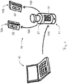
- FIG. 10 shows a first exemplary embodiment of a data distribution system for a group 10 of electronic devices.
- these include a laser beam projection device 11 used in construction, as well as two identical laser beam receiving devices 12a, 12b cooperating with it.
- Each of the devices 11, 12a, 12b has a display unit 31, 32, which can be configured, for example, as an LCD display, touchscreen or e-paper.
- Various product information can be displayed on these displays. This includes, among other things, a product name, serial, customer or rental contract number, return date and place, as well as selected, ie activated, functions of the device. This feature reduces errors e.g. B. when issuing or returning rental equipment or the correct configuration of the equipment according to customer requirements.
- a computer 41 transmits data to the group to be displayed on each of the devices in the group.
- this data is not transmitted to each individual device.
- a first device here the projection device 11, has a first communication unit 21 with a display unit 31.
- the data are only transmitted from the computer 41 to this first communication unit 21 (arrow 110).
- the data are revised by the first communication unit 21, for example decrypted and compared with data that has already been stored. They are then displayed on the display unit 31 and then forwarded to the other devices 12a, b (arrow 120), e.g. B. by means of radio or near-field communication, where they are then also displayed on their display units 32.
- a tenant of the illustrated device group 10 comprising laser beam projection device 11 and two receiving devices 12a, 12b acquires new functions (licenses) for the rented devices by means of software installed on his PC 41.
- the software loads the corresponding licenses via the Internet onto the PC 41 and then transfers them to the communication unit 21 of the laser beam projection device 11 - for example by means of WLAN or Bluetooth and preferably encrypted.
- the communication unit 21 receives the data, it is decrypted and evaluated, and the desired functions of the laser beam projection device 11 are activated.
- its communication unit 21 checks the configuration stored in the communication unit of this receiving device 12a and updates it. Updated data are then displayed on the display unit 32 in accordance with the new configuration.
- the updated information can also include static information such as a product name or a serial number, as well as data relevant to the rental contract (e.g. agreed return location and date or the tenant's name), group-related data (e.g. the names or serial numbers of the devices rented together) or maintenance-related data (e.g. the next maintenance date or a battery level).
- static information such as a product name or a serial number, as well as data relevant to the rental contract (e.g. agreed return location and date or the tenant's name), group-related data (e.g. the names or serial numbers of the devices rented together) or maintenance-related data (e.g. the next maintenance date or a battery level).
- the group 10 can also have a special input and output device that is designed to be held or carried by a user and has a communication unit with a display unit, as well as input means for the user, such as a keypad or a touchscreen Display unit.
- a device can in particular be designed as a wearable, e.g. B. as a smartwatch, VR glasses or an e-garment, or as a smartphone or handheld rangefinder.
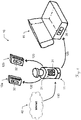
- Figure 2 Figure 3 shows a second exemplary embodiment of the data distribution system.
- the external data from the Internet are transmitted 110 to the communication unit 21, for example via a WLAN network or a cellular network, and as in FIG Figure 1 as described, forwarded 120 to the other devices 12a, b.
- the device group 10 here additionally comprises a protective container 15.
- a protective container has a display unit 35 on its outer shell.
- the first communication unit 21 can transmit 125 the data to the protective container 15 for display on this display unit 35. This can be done, for example, by means of near-field communication when the projection device 11 is located in the protective container 15. Further data from devices located in the protective container 15 can also be transmitted to the latter and can thus be displayed to a user on the display unit 35 even when the container 15 is closed.
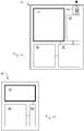
- the Figures 3a and 3b show, purely by way of example and schematically, two interacting communication units 21, 22.
- It shows Figure 3a a first communication unit 21 of the first device 11 from the Figures 1 and 2 .
- This has a display unit 31, which can be configured, for example, as an LCD display, touchscreen or e-ink display and is configured to display data to a user of the device.
- the unit 21 also has a Receiving unit 51 to receive external data.
- the receiving unit 51 is designed as a cellular radio receiving unit with a SIM card for receiving the data via a cellular radio network.
- the data received in this way are forwarded to a computing unit 52, in which the external data are converted into internal data.
- the computing unit 52 has a circuit and an algorithm which are designed to generate configuration data as internal data based on the external data, for which purpose the external data is decrypted, decompressed, reformatted and / or compared with locally stored data and merged .
- Both local data and the external and converted data can be stored in a memory unit 53 of the communication unit 21, for example a memory module or a semiconductor drive.
- the communication unit 21 has a near-field communication device 54 which is designed to exchange data with corresponding devices of other communication units.
- the configuration data can be transmitted to other communication units in this way.
- Figure 3b 1 shows such a second communication unit 22.
- This has a near-field communication device 54 ′, configured to receive data from the corresponding device 54 of the communication unit 21 Figure 3a , and a display unit 32 for displaying information on the basis of the received data.
- the communication unit 21 shown here has neither a receiving unit nor a computing unit.
- the storage unit 53 ' can also be made smaller here, which is why this communication unit 22 is dimensioned significantly smaller and can also be placed on or in correspondingly smaller devices.
- communication devices can also be provided which are designed to exchange data by radio, for example by means of Zigbee, Z-Wave or Bluetooth.
- Figure 4 Figure 3 shows a third exemplary embodiment of the data distribution system.
- the external data are transmitted (arrow 111) via the Internet 40 via a mobile radio network (mobile radio system 43), in contrast to the embodiments from FIG Figure 1 and Figure 2 but not to the projection device 11, but to the laser beam receiver 12a, which has a communication unit 23 with a mobile radio receiver unit.
- this communication unit 23 does not have a computing unit; this is instead provided in the communication unit 22 of the projection device 11.
- the unprocessed data are therefore first forwarded to this communication unit 22 (arrow 112).
- There the data will be revised and, as in Figure 1 and 2 described forwarded to the other devices 12a, b and the protective container 15 (arrows 120, 125).
- a tenant of the illustrated device group 10 comprising laser beam projection device 11, two receiving devices 12a, 12b and protective container 15 acquires new functions (licenses) for the rented devices via an interface of the communication unit of one of the devices, here the receiving device 12a.
- the communication unit 23 of this communication unit loads the corresponding licenses via a cellular connection and the Internet to the receiving device 12a and then transmits it to the communication unit 21 of the laser beam projection device 11 - for example by means of radio or near-field communication.
- the communication unit 21 receives the data, it is decrypted and evaluated, and the desired functions of the laser beam projection device 11 are activated.
- the communication unit 21 checks the configuration stored in the communication unit of this receiving device 12a and updates it. Updated data are then displayed on the display unit 32 in accordance with the new configuration.
- the stored configuration is also checked and updated here.
- the display unit 35 of the protective container 15 then also displays the updated data.
- the connection of the projection device 11 to the protective container 15 can take place both manually and automatically.
- Figure 5 shows a fourth exemplary embodiment of the data distribution system.
- the external data are shown transmitted (arrow 111) via the Internet and a cellular network (cellular radio system 43), in contrast to the embodiments from FIG Figure 4 but not to the laser beam receiver 12a, but to the protective container 15, which has a communication unit with a mobile radio receiver unit.
- the unprocessed data are also forwarded here to the communication unit 22 of the projection device 11 (arrow 115), there processed and then forwarded to the other devices 12a, b and the protective container 15 (arrows 120, 125).
- the protective container 15 can also be a communication unit with the in Figure 3a have functions shown.
- FIG. 6 shows a first exemplary embodiment of the method.
- This method 100 is started in particular by the fact that a user of a group of devices performs a function that makes it necessary to update data on the devices. To do this, he can, for example, activate new functions for a group of rented devices - either using software on a PC or directly on one of the devices.
- This data can include license keys, for example, to activate the functions in the devices. The data are transmitted as soon as the communication unit is ready to receive.
- the next step 113 involves the necessary decryption of the external data in the communication unit.
- the external data in the communication unit are converted, if necessary, into internal configuration data that can be evaluated by the devices.
- the configuration data can then, for example, be used directly to implement the desired functions in the unlock the first device.
- the configuration data or information based on this is displayed in step 131 on a display unit of the communication unit.
- the configuration data are transmitted to the respective communication units in step 120.
- near-field communication can be used for this purpose, the communication units each having an RFID module.
- step 131, 132 On a display unit of the respective communication unit. For example, they are also used to activate the desired functions in the other devices.
- Figure 7 shows a second exemplary embodiment of the method.
- the external data are not sent to the first device, but to a second. From this the data are forwarded in step 112 to the first, where they are as in Figure 6 described can be decrypted (step 113) and used to generate the configuration data (step 114). The configuration data are then, among other things, also transmitted back to the second device from the first device (step 120).
- Figure 8 shows a third exemplary embodiment of the method.
- the first device in a protective container.
- the data required for the update are transmitted to the communication unit of the first device, where in step 114 the configuration data are generated.
- the first device Since the first device is in the protective container, information based on the configuration data can be displayed on the device itself, but is only visible to the user after opening the container.
- the configuration data are therefore advantageously transmitted to a communication unit of the protective container in the next step 125, in particular by means of near-field communication, so that the information is displayed in step 135 on a display unit of the protective container.
- the configuration data are also transmitted to the other devices in step 120. If they are outside the protective container, the data can be transmitted via an external communication unit of the protective container and then displayed on the second and third device (steps 132, 133). If the other devices are also located in the protective container, the data can also be transmitted directly from the communication unit of the first device by means of near-field communication. In addition or as an alternative to the display on the devices, which are not visible to the user inside the container, the data can be transmitted to the protective container for display on the display unit of the latter.
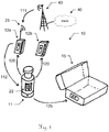
- FIG. 9 schematically illustrates an application example for an embodiment of the method and system according to the invention. Shown is the infrastructure of a landlord with several locations A, B and C. Each of the locations is connected to a server via the Internet and can access its data. This can either be a server belonging to the landlord himself or, for example, belong to the manufacturer or distributor of the equipment to be rented.
- an end customer rents a group 10 of devices that are available in the warehouse at location C and orders a specific configuration. This is entered in a database of a local personal computer, whereupon the license keys corresponding to the rented devices and the configuration ordered are retrieved from the server via the Internet. Then the devices of group 10 are configured, i. H. the license keys and any other configuration data are transferred to the devices. As described above, this is preferably done by transmitting the data to the communication unit of a main device.
- the further configuration data include, in particular, data relevant to the rental agreement, that is to say, for example, on the tenant, landlord, rental period and rented device group 10 (e.g. number and identity of all devices in the group).
- the devices When handing over to the customer, the devices already display information corresponding to the configuration data, so that the risk of errors is significantly reduced.
- the configuration data can also be updated on site (e.g. via a cellular connection), for example if further functions of the devices are to be activated or the lease term is to be extended.
- the information displayed on the devices also significantly reduces the risk of errors when they are returned.
- At least one of the communication units of the group is designed to record usage data of at least one device of the group. These can include, for example, acceleration or localization data of the devices, as well as usage times and functionalities used.
- the corresponding communication unit also has an algorithm that is designed to create a usage profile based on the recorded usage data and, based on this, automatically suggests suitable functions to the user, which can then be activated directly by the user.
- a proposal for functions that can be enabled can be presented in particular on one of the display devices. This saves time and prevents unnecessary replacement of devices.
- the algorithm can be designed to find out whether a device in the group already has a certain functionality or supports it. If the user needs a certain functionality on a construction site that a device available to him does not provide, a location of another device providing the function on the same construction site can be displayed on the display unit by means of this algorithm. For example, the user has an older device that does not support a certain new function. The user can then identify possible functions of other devices on the construction site (e.g. with the help of a map on the display), where there is a device with the appropriate functions, which are available in the device that the user has available (i.e. in particular currently in hand holds), or the associated device group, are not available. For example, he can then automatically reserve the required device or device group.
- a location of another device providing the function on the same construction site can be displayed on the display unit by means of this algorithm. For example, the user has an older device that does not support a certain new function.
- the user can then identify possible functions of other devices on the construction site (e.g.
- this algorithm can be provided wholly or partially externally, in particular on a server or in a cloud, with the data being transmitted by means of the receiving unit, for example via the Internet.
Claims (14)
- Système de distribution de données dans un groupe (10) d'appareils électroniques coopérants qui présentent une multitude de fonctions à débloquer individuellement, cependant que les appareils électroniques coopérants présentent au moins un appareil de projection de faisceau laser (11) et au moins un appareil de réception de faisceau laser (12a, b) agencé pour recevoir un faisceau laser de l'appareil de projection de faisceau laser, cependant que- l'appareil de projection de faisceau laser (11) et le au moins un appareil de réception de faisceau laser sont agencés pour être utilisés lors de la construction de bâtiments ou d'autres structures dans le cadre de travaux de mesure dans le domaine d'installations de construction et sont destinés à être utilisés ensemble et à coopérer sur le plan opérationnel ;- l'un des appareils présente une première unité électronique de communication (21, 23) ;- l'autre appareil ou les autres appareils présentent chacun une autre unité de communication (22) ;- les unités de communication (22) sont agencées pour échanger des données internes entre elles et- la première unité de communication (21, 23) présente une unité de réception (51) qui est agencée pour recevoir des données externes d'une unité informatique externe (41),
caractérisé en ce que- la première unité de communication (21, 23) ou une autre unité de communication (22) présente une unité de calcul (52) avec un algorithme, cependant que l'algorithme est configuré pour générer, sur la base des données externes, des données de configuration comme données internes et est configuré pour transmettre les données de configuration à au moins une autre unité de communication du système ;- la première unité de communication (21, 23) ou une autre unité de communication (22) présente un dispositif d'affichage numérique (31, 32) pour l'affichage visuel d'informations pour un utilisateur, cependant que le dispositif d'affichage (31, 32) est configuré pour afficher, sur la base des données de configuration, des informations actualisées et- qu'au moins une des autres unités de communication (22) présente une unité de commande qui est agencée pour commander l'appareil électronique correspondant (11, 12a, b) sur la base des données de configuration, cependant que la commande comprend une mise en circuit ou une mise hors circuit de fonctions de l'appareil (11, 12a, b),cependant que, lorsque ce n'est pas la première unité de communication (21, 23) qui présente l'unité de calcul (52) avec l'algorithme, la première unité de communication (21, 23) est agencée pour transmettre les données externes reçues à l'unité de communication (22) qui présente l'unité de calcul (52) avec l'algorithme. - Système selon la revendication 1, caractérisé en ce que les unités de communication (21, 22, 23) sont agencées pour échanger les données internes entre elles au moyen de communication en champ proche, en particulier cependant que chacune des unités de communication (21, 22, 23) présente un module RFID.
- Système selon la revendication 1 ou la revendication 2,
caractérisé en ce que l'unité de réception (51)- est agencée comme une unité de réception de radio mobile pour recevoir les données externes par un réseau de radio mobile et/ou- est agencée comme une unité de réception LPN pour recevoir les données externes par un réseau basse énergie, en particulier LoRa ou SigFox,en particulier cependant que l'unité de réception (51) est agencée pour recueillir des demandes de l'unité informatique externe (41). - Système selon l'une des revendications précédentes,
caractérisé en ce que
les données externes présentent des données qui se réfèrent à une licence, en particulier des clés de licence, pour les au moins deux appareils électroniques (11, 12a, b). - Système selon l'une des revendications précédentes,
caractérisé en ce que
les données externes sont cryptées et l'unité de calcul (52) présente un algorithme qui est agencé pour décrypter les données externes. - Système selon l'une des revendications précédentes,
caractérisé en ce que la première unité de communication (21, 23) présente l'unité de réception (51) aussi bien que l'unité de calcul (52). - Système selon l'une des revendications 1 à 5,
caractérisé en ce
qu'une seconde unité de communication (22) présente l'unité de calcul (52) et est agencée pour transmettre les données de configuration au moins à la première unité de communication (21, 23). - Système selon l'une des revendications 1 à 5,
caractérisé en ce
qu'un premier appareil de réception de faisceau laser (12a) présente la première unité de communication (23) et l'appareil de projection de faisceau laser (11) une seconde unité de communication (22), cependant que la seconde unité de communication (22) présente l'unité de calcul (52) et est agencée pour transmettre les données de configuration au moins à la première unité de communication (23). - Système selon l'une des revendications précédentes,
caractérisé en ce
qu'au moins une des unités de communication (21, 22, 23) est agencée pour saisir des données d'utilisation d'au moins un appareil (11, 12a, b) du groupe (10), à des intervalles définis, en particulier cependant que l'unité de communication correspondante présente un algorithme qui est agencé pour établir un profil d'utilisation et de présenter à l'utilisateur, sur la base du profil d'utilisation, une proposition de fonctions pouvant être débloquées pour l'au moins un appareil (11, 12a, b) sur un dispositif d'affichage (31, 32). - Système selon la revendication 9,
caractérisé en ce que- les données internes comprennent des données de maintenance avec des informations sur une date de maintenance d'au moins un appareil (11, 12a, b) du groupe (10) et- le dispositif d'affichage (31, 32) de l'au moins un appareil (11, 12a, b) est agencé pour afficher la date de maintenance,
cependant qu'au moins une des unités de communication (21, 22, 23)- présente une unité de statistique avec un algorithme qui est agencée pour calculer, sur la base des données d'utilisation d'au moins un appareil (11, 12a, b) du groupe (10), la date de maintenance ou- est agencée pour envoyer les données d'utilisation d'au moins un appareil (11, 12a, b) à l'unité informatique externe (41), les données externes comprenant des informations sur la date de maintenance et l'algorithme de l'unité de calcul (52) est agencée pour générer les données de maintenance sur la base des données externes. - Système selon l'une des revendications précédentes,
caractérisé en ce
qu'au moins une des unités de communication (21, 22, 23) présente une mémoire de données (53) et est agencée- pour saisir ou accéder aux informations sur des appareils (11, 12a, b) du groupe (10),- pour mémoriser des informations saisies ou demandées dans la mémoire de données (53) et- pour afficher les informations pour un utilisateur sur le dispositif d'affichage (31, 32),en particulier cependant que les informations sur un appareil (11, 12a, b) comprennent des informations sur un emplacement de l'appareil (11, 12a, b) et des fonctions débloquées de l'appareil (11, 12a, b). - Système selon l'une des revendications précédentes,
caractérisé en ce
qu'au moins une des unités de communication (21, 22, 23) est agencée- pour détecter à quelles autres unités de communication (21, 22, 23) des données de configuration actuelles ont déjà été transmises et- pour afficher pour un utilisateur sur le dispositif d'affichage (31, 32) auxquelles unités de communication (21, 22, 23) de quels appareils (11, 12a, b) les données actuelles de configuration doivent encore être transmises. - Système selon l'une des revendications précédentes,
caractérisé en ce
que le groupe (10) comprend au moins un conteneur protecteur (15) qui présente un espace intérieur qui est agencé pour accueillir au moins l'un des appareils électroniques (11, 12a, b), cependant- qu'il est prévu un dispositif d'affichage numérique (35) sur une enveloppe extérieure du conteneur protecteur (15) et- qu'une unité de communication du conteneur protecteur (15) est agencée comme unité de communication de l'espace intérieur pour la communication avec des unités de communication (21, 22, 23) d'appareils électroniques (11, 12a, b) qui se trouvent dans l'espace intérieur. - Procédé (100) pour actualiser des données d'un groupe (10) d'au moins deux appareils électroniques qui coopèrent (11, 12) qui présentent une multitude de fonctions à débloquer individuellement, cependant que les appareils électroniques coopérants présentent au moins un appareil de projection de faisceau laser (11) et au moins un appareil de réception de faisceau laser (12a, b) agencé pour recevoir un faisceau laser de l'appareil de projection de faisceau laser, cependant que l'appareil de projection de faisceau laser (11) et le au moins un appareil de réception de faisceau laser (12a, b)sont agencés pour être utilisés lors de la construction de bâtiments ou d'autres structures dans le cadre de travaux de mesure dans le domaine des installations de construction et sont destinés à être utilisés ensemble et à coopérer sur le plan opérationnel, l'un des appareils présente une première unité électronique de communication (21, 23), l'autre appareil ou les autres appareils présentent chacun une autre unité de communication (22) et les unités de communication (22) sont agencées pour échanger des données internes entre elles avec- une réception de données externes d'une unité informatique externe (41) par une unité de réception (51) de la première unité électronique de communication (21,23) ;- une génération, sur la base des données externes, de données de configuration comme données internes par un algorithme d'une unité de calcul (52) d'une des unités de communication (21, 22, 23) ;- une transmission des données de configuration à au moins une autre des unités de communication (21, 22, 23) ;- un affichage d'informations actualisées, sur la base des données de configuration, sur un dispositif d'affichage (31, 32) d'au moins l'une des unités de communication (21, 22, 23) et- une commande d'au moins un appareil électronique (11, 12a, b) du groupe (10) qui présente une des autres unités de communication (22) par l'autre unité de communication correspondante (22) sur la base des données de configuration, cependant que la commande comprend une mise en circuit ou une mise hors circuit de fonctions de l'appareil 11, 12a, b),cependant que, lorsque ce n'est pas la première unité de communication (21,23) qui présente l'unité de calcul (52) avec l'algorithme, les données externes reçues sont transmises à l'unité de communication (22) qui présente l'unité de calcul (52) avec l'algorithme.
Priority Applications (3)
| Application Number | Priority Date | Filing Date | Title |
|---|---|---|---|
| EP17167585.3A EP3392811B1 (fr) | 2017-04-21 | 2017-04-21 | Système et procédé de distribution des données à des appareils électroniques |
| CN201810353119.5A CN108734546B (zh) | 2017-04-21 | 2018-04-19 | 用于一组电子装置的数据分配的系统和方法 |
| US15/959,197 US11755005B2 (en) | 2017-04-21 | 2018-04-21 | Data distribution system and method for a group of electronics devices |
Applications Claiming Priority (1)
| Application Number | Priority Date | Filing Date | Title |
|---|---|---|---|
| EP17167585.3A EP3392811B1 (fr) | 2017-04-21 | 2017-04-21 | Système et procédé de distribution des données à des appareils électroniques |
Publications (2)
| Publication Number | Publication Date |
|---|---|
| EP3392811A1 EP3392811A1 (fr) | 2018-10-24 |
| EP3392811B1 true EP3392811B1 (fr) | 2021-08-18 |
Family
ID=58664492
Family Applications (1)
| Application Number | Title | Priority Date | Filing Date |
|---|---|---|---|
| EP17167585.3A Active EP3392811B1 (fr) | 2017-04-21 | 2017-04-21 | Système et procédé de distribution des données à des appareils électroniques |
Country Status (3)
| Country | Link |
|---|---|
| US (1) | US11755005B2 (fr) |
| EP (1) | EP3392811B1 (fr) |
| CN (1) | CN108734546B (fr) |
Families Citing this family (1)
| Publication number | Priority date | Publication date | Assignee | Title |
|---|---|---|---|---|
| EP3579161A1 (fr) | 2018-06-08 | 2019-12-11 | Hexagon Technology Center GmbH | Déploiement de flux de travail |
Citations (2)
| Publication number | Priority date | Publication date | Assignee | Title |
|---|---|---|---|---|
| WO2013063507A1 (fr) * | 2011-10-26 | 2013-05-02 | Milwaukee Electric Tool Corporation | Suivi sans fil d'outils électriques et dispositifs associés |
| EP3002742A1 (fr) * | 2014-09-19 | 2016-04-06 | Sears Brands, LLC | Procédé et système pour activer une commande sans fil dans des outils par utilisation de systèmes d'alimentation électrique portables avec des composants de communication intégré |
Family Cites Families (31)
| Publication number | Priority date | Publication date | Assignee | Title |
|---|---|---|---|---|
| US6230081B1 (en) * | 1996-02-15 | 2001-05-08 | Christian Albertshofer | Information system for golf carts and system for calculation of use and/or acquisition of use data |
| JP2001160106A (ja) * | 1999-09-21 | 2001-06-12 | Olympus Optical Co Ltd | 医療機器リース方法、医療機器リースシステム及び医療機器 |
| JP4565703B2 (ja) * | 2000-05-16 | 2010-10-20 | グローリー株式会社 | データ記憶装置およびデータ記憶方法 |
| AU2003210490B2 (en) | 2002-01-11 | 2008-07-10 | Sap Aktiengesellschaft | Context-aware and real-time item tracking system architecture and scenarios |
| US7421499B1 (en) * | 2002-04-10 | 2008-09-02 | At&T Corp. | Automated adjustment of IP address lease time based on usage |
| WO2003090125A2 (fr) * | 2002-04-19 | 2003-10-30 | Computer Associates Think, Inc. | Procede et systeme de distribution de donnees |
| JP4546967B2 (ja) * | 2003-10-22 | 2010-09-22 | ライカ ジオシステムズ アクチェンゲゼルシャフト | ワークサイト上の装置間情報交換管理方法とその装置 |
| US6845279B1 (en) * | 2004-02-06 | 2005-01-18 | Integrated Technologies, Inc. | Error proofing system for portable tools |
| US20050228877A1 (en) * | 2004-04-07 | 2005-10-13 | Arnold Monitzer | System for managing a device |
| US20060273918A1 (en) * | 2005-06-07 | 2006-12-07 | Ram Satish N | System for providing multiple maintenance profiles using wireless communications |
| WO2007139587A1 (fr) * | 2006-05-26 | 2007-12-06 | The Board Of Regents Of The Nevada System Of Higher Education On Behalf Of The Desert Research Institute | Systèmes de surveillance de services et procédés d'utilisation |
| US9858712B2 (en) * | 2007-04-09 | 2018-01-02 | Sam Stathis | System and method capable of navigating and/or mapping any multi-dimensional space |
| AU2008327506B2 (en) * | 2007-07-31 | 2012-06-07 | Artus, Karen Mary | Method and system for encryption of data |
| US20100153732A1 (en) | 2008-12-15 | 2010-06-17 | Stmicroelectronics Rousset Sas | cache-based method of hash-tree management for protecting data integrity |
| US20100299172A1 (en) * | 2009-05-20 | 2010-11-25 | The Walsh Group Ltd. | Equipment management system |
| US9749792B2 (en) * | 2009-08-11 | 2017-08-29 | Michael Edward Klicpera | Water use monitoring apparatus |
| US8589304B2 (en) * | 2011-03-14 | 2013-11-19 | Splunk Inc. | System and method for controlling the indexing of volume between network devices |
| EP2741049A1 (fr) | 2012-12-05 | 2014-06-11 | Leica Geosystems AG | Dispositif de vérification de la fidélité de l'horizontalité du faisceau laser et procédé correspondant |
| HK1183407A2 (en) * | 2013-01-21 | 2013-12-20 | 3 P M Holding Ltd | Accessory enclosure and input device |
| US9499128B2 (en) * | 2013-03-14 | 2016-11-22 | The Crawford Group, Inc. | Mobile device-enhanced user selection of specific rental vehicles for a rental vehicle reservation |
| US9391662B2 (en) * | 2013-04-30 | 2016-07-12 | Samsung Electronics Co., Ltd | Portable electronic device, flip-type cover of the portable electronic device, and method for controlling the flip-type cover |
| GB2519120B (en) * | 2013-10-10 | 2017-10-18 | Abb Ltd | Methods and apparatus relating to measurement instruments |
| US9838525B2 (en) * | 2014-01-03 | 2017-12-05 | General Electric Company | Systems and methods for coupling auxiliary devices to a utility meter |
| WO2015153008A2 (fr) * | 2014-04-02 | 2015-10-08 | Ridge Tool Company | Verrouillage d'outil électronique |
| US9734693B2 (en) * | 2014-07-09 | 2017-08-15 | Mckinley Equipment Corporation | Remote equipment monitoring and notification using a server system |
| US20160132839A1 (en) * | 2014-11-08 | 2016-05-12 | Facilities Maintenance Planning, LLC | Systems and processes for facilities maintenance scheduling |
| AU2016257438B2 (en) * | 2015-05-04 | 2019-03-07 | Milwaukee Electric Tool Corporation | Power tool and method for wireless communication |
| US20170017305A1 (en) * | 2015-07-15 | 2017-01-19 | Samsung Electronics Co., Ltd. | Electronic device and method for controlling the same |
| EP3173736A1 (fr) * | 2015-11-24 | 2017-05-31 | Leica Geosystems AG | Récipient de sécurité pour appareils de mesure |
| KR20170065295A (ko) * | 2015-12-03 | 2017-06-13 | 삼성전자주식회사 | 외부 전자 장치를 제어하는 전자 장치 및 동작 방법 |
| US10809702B2 (en) * | 2016-10-17 | 2020-10-20 | Fisher-Rosemount Systems, Inc. | Mobile devices for remote access of process control data |
-
2017
- 2017-04-21 EP EP17167585.3A patent/EP3392811B1/fr active Active
-
2018
- 2018-04-19 CN CN201810353119.5A patent/CN108734546B/zh active Active
- 2018-04-21 US US15/959,197 patent/US11755005B2/en active Active
Patent Citations (2)
| Publication number | Priority date | Publication date | Assignee | Title |
|---|---|---|---|---|
| WO2013063507A1 (fr) * | 2011-10-26 | 2013-05-02 | Milwaukee Electric Tool Corporation | Suivi sans fil d'outils électriques et dispositifs associés |
| EP3002742A1 (fr) * | 2014-09-19 | 2016-04-06 | Sears Brands, LLC | Procédé et système pour activer une commande sans fil dans des outils par utilisation de systèmes d'alimentation électrique portables avec des composants de communication intégré |
Also Published As
| Publication number | Publication date |
|---|---|
| CN108734546A (zh) | 2018-11-02 |
| CN108734546B (zh) | 2022-05-10 |
| US20180307222A1 (en) | 2018-10-25 |
| US11755005B2 (en) | 2023-09-12 |
| EP3392811A1 (fr) | 2018-10-24 |
Similar Documents
| Publication | Publication Date | Title |
|---|---|---|
| DE60224564T2 (de) | Dynamische bedienerfunktionen auf der basis der bedienerposition | |
| DE102010041548B4 (de) | Ortungssystem und Verfahren zur Bestimmung der Positionen von Gegenständen | |
| WO2008116626A1 (fr) | Unité fonctionnelle électrique à commande sans fil pour aéronef | |
| EP1405041B1 (fr) | Procede de collecte des donnees valeurs affichees aux compteurs et systeme de collecte de ces donnees | |
| DE112015004412T5 (de) | Vorrichtung für das produktinformationsmanagement | |
| EP3392811B1 (fr) | Système et procédé de distribution des données à des appareils électroniques | |
| DE112006002054B4 (de) | Managementsystem für technische und/oder bauliche Anlagen | |
| DE202015009876U1 (de) | Autonomes elektronisches Preisschild | |
| EP3101613B1 (fr) | Étiquette de prix autonome électronique | |
| EP3984254A1 (fr) | Procédé de localisation d'une étiquette électronique pour rayonnage | |
| DE112010001585T5 (de) | Beweglicher Körper und System zum Verwaltenvon Inventarinformationen des beweglichen Körpers | |
| EP2175401B1 (fr) | Transpondeur | |
| DE112011105919B4 (de) | Karteninformations-Verarbeitungsvorrichtung | |
| DE102022104945A1 (de) | Verfahren zur Nachverfolgung eines Gerätes, Gerät sowie Arbeitssystem | |
| DE202019103774U1 (de) | Geräteverbund zur Veranschaulichung des Baufortschritts auf den Baustellen einer Linienbaustelle | |
| DE102019127810B4 (de) | Verfahren zur zeitspezifischen Ermittlung des Standorts einer Person | |
| EP1029321A2 (fr) | Element d'affichage, commande pour element d'affichage, procede de commande correspondant, element registre et systeme d'enregistrement | |
| EP1245021B1 (fr) | Procede de transmission d'informations specifiques d'emplacements | |
| EP3929830A1 (fr) | Procédé d'enregistrement automatique du temps de travail et/ou de détermination automatique de la position d'une personne dans un environnement prédéterminé et système de détection | |
| DE102012101567A1 (de) | Konfigurationssystem für ein Netzwerkendgerät | |
| DE102014106007A1 (de) | Verfahren zum Anzeigen und Aktualisieren von an einer Benutzerschnittstelle angezeigten Dokumenten | |
| DE102022119171A1 (de) | Verfahren und Vorrichtung für das Nachbestellen von Verbrauchsmaterialien | |
| DE102021115757A1 (de) | Personenleitsystem | |
| DE102019126000A1 (de) | System zur Darstellung von Vorgängen | |
| DE102012208135A1 (de) | Zuordnen eines Auftrags von einem Auftraggeber an einen Auftragnehmer |
Legal Events
| Date | Code | Title | Description |
|---|---|---|---|
| PUAI | Public reference made under article 153(3) epc to a published international application that has entered the european phase |
Free format text: ORIGINAL CODE: 0009012 |
|
| STAA | Information on the status of an ep patent application or granted ep patent |
Free format text: STATUS: THE APPLICATION HAS BEEN PUBLISHED |
|
| AK | Designated contracting states |
Kind code of ref document: A1 Designated state(s): AL AT BE BG CH CY CZ DE DK EE ES FI FR GB GR HR HU IE IS IT LI LT LU LV MC MK MT NL NO PL PT RO RS SE SI SK SM TR |
|
| AX | Request for extension of the european patent |
Extension state: BA ME |
|
| STAA | Information on the status of an ep patent application or granted ep patent |
Free format text: STATUS: REQUEST FOR EXAMINATION WAS MADE |
|
| STAA | Information on the status of an ep patent application or granted ep patent |
Free format text: STATUS: EXAMINATION IS IN PROGRESS |
|
| 17P | Request for examination filed |
Effective date: 20190423 |
|
| RBV | Designated contracting states (corrected) |
Designated state(s): AL AT BE BG CH CY CZ DE DK EE ES FI FR GB GR HR HU IE IS IT LI LT LU LV MC MK MT NL NO PL PT RO RS SE SI SK SM TR |
|
| 17Q | First examination report despatched |
Effective date: 20190529 |
|
| STAA | Information on the status of an ep patent application or granted ep patent |
Free format text: STATUS: EXAMINATION IS IN PROGRESS |
|
| GRAP | Despatch of communication of intention to grant a patent |
Free format text: ORIGINAL CODE: EPIDOSNIGR1 |
|
| STAA | Information on the status of an ep patent application or granted ep patent |
Free format text: STATUS: GRANT OF PATENT IS INTENDED |
|
| INTG | Intention to grant announced |
Effective date: 20210316 |
|
| GRAS | Grant fee paid |
Free format text: ORIGINAL CODE: EPIDOSNIGR3 |
|
| GRAA | (expected) grant |
Free format text: ORIGINAL CODE: 0009210 |
|
| STAA | Information on the status of an ep patent application or granted ep patent |
Free format text: STATUS: THE PATENT HAS BEEN GRANTED |
|
| AK | Designated contracting states |
Kind code of ref document: B1 Designated state(s): AL AT BE BG CH CY CZ DE DK EE ES FI FR GB GR HR HU IE IS IT LI LT LU LV MC MK MT NL NO PL PT RO RS SE SI SK SM TR |
|
| REG | Reference to a national code |
Ref country code: GB Ref legal event code: FG4D Free format text: NOT ENGLISH |
|
| REG | Reference to a national code |
Ref country code: CH Ref legal event code: EP |
|
| REG | Reference to a national code |
Ref country code: DE Ref legal event code: R096 Ref document number: 502017011208 Country of ref document: DE |
|
| REG | Reference to a national code |
Ref country code: IE Ref legal event code: FG4D Free format text: LANGUAGE OF EP DOCUMENT: GERMAN Ref country code: AT Ref legal event code: REF Ref document number: 1422304 Country of ref document: AT Kind code of ref document: T Effective date: 20210915 |
|
| REG | Reference to a national code |
Ref country code: LT Ref legal event code: MG9D |
|
| REG | Reference to a national code |
Ref country code: NL Ref legal event code: MP Effective date: 20210818 |
|
| PG25 | Lapsed in a contracting state [announced via postgrant information from national office to epo] |
Ref country code: RS Free format text: LAPSE BECAUSE OF FAILURE TO SUBMIT A TRANSLATION OF THE DESCRIPTION OR TO PAY THE FEE WITHIN THE PRESCRIBED TIME-LIMIT Effective date: 20210818 Ref country code: SE Free format text: LAPSE BECAUSE OF FAILURE TO SUBMIT A TRANSLATION OF THE DESCRIPTION OR TO PAY THE FEE WITHIN THE PRESCRIBED TIME-LIMIT Effective date: 20210818 Ref country code: NO Free format text: LAPSE BECAUSE OF FAILURE TO SUBMIT A TRANSLATION OF THE DESCRIPTION OR TO PAY THE FEE WITHIN THE PRESCRIBED TIME-LIMIT Effective date: 20211118 Ref country code: PT Free format text: LAPSE BECAUSE OF FAILURE TO SUBMIT A TRANSLATION OF THE DESCRIPTION OR TO PAY THE FEE WITHIN THE PRESCRIBED TIME-LIMIT Effective date: 20211220 Ref country code: HR Free format text: LAPSE BECAUSE OF FAILURE TO SUBMIT A TRANSLATION OF THE DESCRIPTION OR TO PAY THE FEE WITHIN THE PRESCRIBED TIME-LIMIT Effective date: 20210818 Ref country code: ES Free format text: LAPSE BECAUSE OF FAILURE TO SUBMIT A TRANSLATION OF THE DESCRIPTION OR TO PAY THE FEE WITHIN THE PRESCRIBED TIME-LIMIT Effective date: 20210818 Ref country code: FI Free format text: LAPSE BECAUSE OF FAILURE TO SUBMIT A TRANSLATION OF THE DESCRIPTION OR TO PAY THE FEE WITHIN THE PRESCRIBED TIME-LIMIT Effective date: 20210818 Ref country code: LT Free format text: LAPSE BECAUSE OF FAILURE TO SUBMIT A TRANSLATION OF THE DESCRIPTION OR TO PAY THE FEE WITHIN THE PRESCRIBED TIME-LIMIT Effective date: 20210818 Ref country code: BG Free format text: LAPSE BECAUSE OF FAILURE TO SUBMIT A TRANSLATION OF THE DESCRIPTION OR TO PAY THE FEE WITHIN THE PRESCRIBED TIME-LIMIT Effective date: 20211118 |
|
| PG25 | Lapsed in a contracting state [announced via postgrant information from national office to epo] |
Ref country code: PL Free format text: LAPSE BECAUSE OF FAILURE TO SUBMIT A TRANSLATION OF THE DESCRIPTION OR TO PAY THE FEE WITHIN THE PRESCRIBED TIME-LIMIT Effective date: 20210818 Ref country code: LV Free format text: LAPSE BECAUSE OF FAILURE TO SUBMIT A TRANSLATION OF THE DESCRIPTION OR TO PAY THE FEE WITHIN THE PRESCRIBED TIME-LIMIT Effective date: 20210818 Ref country code: GR Free format text: LAPSE BECAUSE OF FAILURE TO SUBMIT A TRANSLATION OF THE DESCRIPTION OR TO PAY THE FEE WITHIN THE PRESCRIBED TIME-LIMIT Effective date: 20211119 |
|
| PG25 | Lapsed in a contracting state [announced via postgrant information from national office to epo] |
Ref country code: NL Free format text: LAPSE BECAUSE OF FAILURE TO SUBMIT A TRANSLATION OF THE DESCRIPTION OR TO PAY THE FEE WITHIN THE PRESCRIBED TIME-LIMIT Effective date: 20210818 |
|
| PG25 | Lapsed in a contracting state [announced via postgrant information from national office to epo] |
Ref country code: DK Free format text: LAPSE BECAUSE OF FAILURE TO SUBMIT A TRANSLATION OF THE DESCRIPTION OR TO PAY THE FEE WITHIN THE PRESCRIBED TIME-LIMIT Effective date: 20210818 |
|
| REG | Reference to a national code |
Ref country code: DE Ref legal event code: R097 Ref document number: 502017011208 Country of ref document: DE |
|
| PG25 | Lapsed in a contracting state [announced via postgrant information from national office to epo] |
Ref country code: SM Free format text: LAPSE BECAUSE OF FAILURE TO SUBMIT A TRANSLATION OF THE DESCRIPTION OR TO PAY THE FEE WITHIN THE PRESCRIBED TIME-LIMIT Effective date: 20210818 Ref country code: SK Free format text: LAPSE BECAUSE OF FAILURE TO SUBMIT A TRANSLATION OF THE DESCRIPTION OR TO PAY THE FEE WITHIN THE PRESCRIBED TIME-LIMIT Effective date: 20210818 Ref country code: RO Free format text: LAPSE BECAUSE OF FAILURE TO SUBMIT A TRANSLATION OF THE DESCRIPTION OR TO PAY THE FEE WITHIN THE PRESCRIBED TIME-LIMIT Effective date: 20210818 Ref country code: EE Free format text: LAPSE BECAUSE OF FAILURE TO SUBMIT A TRANSLATION OF THE DESCRIPTION OR TO PAY THE FEE WITHIN THE PRESCRIBED TIME-LIMIT Effective date: 20210818 Ref country code: CZ Free format text: LAPSE BECAUSE OF FAILURE TO SUBMIT A TRANSLATION OF THE DESCRIPTION OR TO PAY THE FEE WITHIN THE PRESCRIBED TIME-LIMIT Effective date: 20210818 Ref country code: AL Free format text: LAPSE BECAUSE OF FAILURE TO SUBMIT A TRANSLATION OF THE DESCRIPTION OR TO PAY THE FEE WITHIN THE PRESCRIBED TIME-LIMIT Effective date: 20210818 |
|
| PLBE | No opposition filed within time limit |
Free format text: ORIGINAL CODE: 0009261 |
|
| STAA | Information on the status of an ep patent application or granted ep patent |
Free format text: STATUS: NO OPPOSITION FILED WITHIN TIME LIMIT |
|
| 26N | No opposition filed |
Effective date: 20220519 |
|
| PG25 | Lapsed in a contracting state [announced via postgrant information from national office to epo] |
Ref country code: SI Free format text: LAPSE BECAUSE OF FAILURE TO SUBMIT A TRANSLATION OF THE DESCRIPTION OR TO PAY THE FEE WITHIN THE PRESCRIBED TIME-LIMIT Effective date: 20210818 |
|
| REG | Reference to a national code |
Ref country code: BE Ref legal event code: MM Effective date: 20220430 |
|
| PG25 | Lapsed in a contracting state [announced via postgrant information from national office to epo] |
Ref country code: MC Free format text: LAPSE BECAUSE OF FAILURE TO SUBMIT A TRANSLATION OF THE DESCRIPTION OR TO PAY THE FEE WITHIN THE PRESCRIBED TIME-LIMIT Effective date: 20210818 Ref country code: LU Free format text: LAPSE BECAUSE OF NON-PAYMENT OF DUE FEES Effective date: 20220421 |
|
| PG25 | Lapsed in a contracting state [announced via postgrant information from national office to epo] |
Ref country code: BE Free format text: LAPSE BECAUSE OF NON-PAYMENT OF DUE FEES Effective date: 20220430 |
|
| PG25 | Lapsed in a contracting state [announced via postgrant information from national office to epo] |
Ref country code: IE Free format text: LAPSE BECAUSE OF NON-PAYMENT OF DUE FEES Effective date: 20220421 |
|
| REG | Reference to a national code |
Ref country code: AT Ref legal event code: MM01 Ref document number: 1422304 Country of ref document: AT Kind code of ref document: T Effective date: 20220421 |
|
| PG25 | Lapsed in a contracting state [announced via postgrant information from national office to epo] |
Ref country code: AT Free format text: LAPSE BECAUSE OF NON-PAYMENT OF DUE FEES Effective date: 20220421 |
|
| PGFP | Annual fee paid to national office [announced via postgrant information from national office to epo] |
Ref country code: IT Payment date: 20230426 Year of fee payment: 7 Ref country code: FR Payment date: 20230424 Year of fee payment: 7 Ref country code: DE Payment date: 20230420 Year of fee payment: 7 Ref country code: CH Payment date: 20230502 Year of fee payment: 7 |
|
| PGFP | Annual fee paid to national office [announced via postgrant information from national office to epo] |
Ref country code: GB Payment date: 20230419 Year of fee payment: 7 |
|
| PG25 | Lapsed in a contracting state [announced via postgrant information from national office to epo] |
Ref country code: HU Free format text: LAPSE BECAUSE OF FAILURE TO SUBMIT A TRANSLATION OF THE DESCRIPTION OR TO PAY THE FEE WITHIN THE PRESCRIBED TIME-LIMIT; INVALID AB INITIO Effective date: 20170421 |
|
| PG25 | Lapsed in a contracting state [announced via postgrant information from national office to epo] |
Ref country code: MK Free format text: LAPSE BECAUSE OF FAILURE TO SUBMIT A TRANSLATION OF THE DESCRIPTION OR TO PAY THE FEE WITHIN THE PRESCRIBED TIME-LIMIT Effective date: 20210818 Ref country code: CY Free format text: LAPSE BECAUSE OF FAILURE TO SUBMIT A TRANSLATION OF THE DESCRIPTION OR TO PAY THE FEE WITHIN THE PRESCRIBED TIME-LIMIT Effective date: 20210818 |