EP3392811A1 - Datenverteilungssystem und -verfahren für eine gruppe von elektronischen geräten - Google Patents
Datenverteilungssystem und -verfahren für eine gruppe von elektronischen geräten Download PDFInfo
- Publication number
- EP3392811A1 EP3392811A1 EP17167585.3A EP17167585A EP3392811A1 EP 3392811 A1 EP3392811 A1 EP 3392811A1 EP 17167585 A EP17167585 A EP 17167585A EP 3392811 A1 EP3392811 A1 EP 3392811A1
- Authority
- EP
- European Patent Office
- Prior art keywords
- data
- unit
- devices
- communication
- communication units
- Prior art date
- Legal status (The legal status is an assumption and is not a legal conclusion. Google has not performed a legal analysis and makes no representation as to the accuracy of the status listed.)
- Granted
Links
- 238000000034 method Methods 0.000 title claims abstract description 26
- 238000004891 communication Methods 0.000 claims abstract description 138
- 230000001681 protective effect Effects 0.000 claims description 29
- 230000006870 function Effects 0.000 claims description 27
- 238000012423 maintenance Methods 0.000 claims description 14
- QVFWZNCVPCJQOP-UHFFFAOYSA-N chloralodol Chemical compound CC(O)(C)CC(C)OC(O)C(Cl)(Cl)Cl QVFWZNCVPCJQOP-UHFFFAOYSA-N 0.000 claims description 2
- 238000010276 construction Methods 0.000 description 4
- 238000005259 measurement Methods 0.000 description 2
- 230000001133 acceleration Effects 0.000 description 1
- 238000013459 approach Methods 0.000 description 1
- 230000001413 cellular effect Effects 0.000 description 1
- 230000001419 dependent effect Effects 0.000 description 1
- 238000013461 design Methods 0.000 description 1
- 238000001514 detection method Methods 0.000 description 1
- 239000011521 glass Substances 0.000 description 1
- 238000009434 installation Methods 0.000 description 1
- 230000004807 localization Effects 0.000 description 1
- 230000003287 optical effect Effects 0.000 description 1
- 239000004065 semiconductor Substances 0.000 description 1
- 230000003068 static effect Effects 0.000 description 1
- 238000012546 transfer Methods 0.000 description 1
Images


Classifications
-
- G—PHYSICS
- G05—CONTROLLING; REGULATING
- G05B—CONTROL OR REGULATING SYSTEMS IN GENERAL; FUNCTIONAL ELEMENTS OF SUCH SYSTEMS; MONITORING OR TESTING ARRANGEMENTS FOR SUCH SYSTEMS OR ELEMENTS
- G05B23/00—Testing or monitoring of control systems or parts thereof
- G05B23/02—Electric testing or monitoring
- G05B23/0205—Electric testing or monitoring by means of a monitoring system capable of detecting and responding to faults
- G05B23/0259—Electric testing or monitoring by means of a monitoring system capable of detecting and responding to faults characterized by the response to fault detection
- G05B23/0283—Predictive maintenance, e.g. involving the monitoring of a system and, based on the monitoring results, taking decisions on the maintenance schedule of the monitored system; Estimating remaining useful life [RUL]
-
- G—PHYSICS
- G06—COMPUTING; CALCULATING OR COUNTING
- G06Q—INFORMATION AND COMMUNICATION TECHNOLOGY [ICT] SPECIALLY ADAPTED FOR ADMINISTRATIVE, COMMERCIAL, FINANCIAL, MANAGERIAL OR SUPERVISORY PURPOSES; SYSTEMS OR METHODS SPECIALLY ADAPTED FOR ADMINISTRATIVE, COMMERCIAL, FINANCIAL, MANAGERIAL OR SUPERVISORY PURPOSES, NOT OTHERWISE PROVIDED FOR
- G06Q30/00—Commerce
- G06Q30/06—Buying, selling or leasing transactions
- G06Q30/0645—Rental transactions; Leasing transactions
-
- G—PHYSICS
- G05—CONTROLLING; REGULATING
- G05B—CONTROL OR REGULATING SYSTEMS IN GENERAL; FUNCTIONAL ELEMENTS OF SUCH SYSTEMS; MONITORING OR TESTING ARRANGEMENTS FOR SUCH SYSTEMS OR ELEMENTS
- G05B23/00—Testing or monitoring of control systems or parts thereof
- G05B23/02—Electric testing or monitoring
- G05B23/0205—Electric testing or monitoring by means of a monitoring system capable of detecting and responding to faults
- G05B23/0208—Electric testing or monitoring by means of a monitoring system capable of detecting and responding to faults characterized by the configuration of the monitoring system
- G05B23/0216—Human interface functionality, e.g. monitoring system providing help to the user in the selection of tests or in its configuration
-
- G—PHYSICS
- G05—CONTROLLING; REGULATING
- G05B—CONTROL OR REGULATING SYSTEMS IN GENERAL; FUNCTIONAL ELEMENTS OF SUCH SYSTEMS; MONITORING OR TESTING ARRANGEMENTS FOR SUCH SYSTEMS OR ELEMENTS
- G05B23/00—Testing or monitoring of control systems or parts thereof
- G05B23/02—Electric testing or monitoring
- G05B23/0205—Electric testing or monitoring by means of a monitoring system capable of detecting and responding to faults
- G05B23/0259—Electric testing or monitoring by means of a monitoring system capable of detecting and responding to faults characterized by the response to fault detection
- G05B23/0275—Fault isolation and identification, e.g. classify fault; estimate cause or root of failure
- G05B23/0281—Quantitative, e.g. mathematical distance; Clustering; Neural networks; Statistical analysis
-
- G—PHYSICS
- G06—COMPUTING; CALCULATING OR COUNTING
- G06F—ELECTRIC DIGITAL DATA PROCESSING
- G06F21/00—Security arrangements for protecting computers, components thereof, programs or data against unauthorised activity
- G06F21/10—Protecting distributed programs or content, e.g. vending or licensing of copyrighted material ; Digital rights management [DRM]
-
- G—PHYSICS
- G06—COMPUTING; CALCULATING OR COUNTING
- G06K—GRAPHICAL DATA READING; PRESENTATION OF DATA; RECORD CARRIERS; HANDLING RECORD CARRIERS
- G06K17/00—Methods or arrangements for effecting co-operative working between equipments covered by two or more of main groups G06K1/00 - G06K15/00, e.g. automatic card files incorporating conveying and reading operations
- G06K17/0022—Methods or arrangements for effecting co-operative working between equipments covered by two or more of main groups G06K1/00 - G06K15/00, e.g. automatic card files incorporating conveying and reading operations arrangements or provisious for transferring data to distant stations, e.g. from a sensing device
-
- G—PHYSICS
- G06—COMPUTING; CALCULATING OR COUNTING
- G06Q—INFORMATION AND COMMUNICATION TECHNOLOGY [ICT] SPECIALLY ADAPTED FOR ADMINISTRATIVE, COMMERCIAL, FINANCIAL, MANAGERIAL OR SUPERVISORY PURPOSES; SYSTEMS OR METHODS SPECIALLY ADAPTED FOR ADMINISTRATIVE, COMMERCIAL, FINANCIAL, MANAGERIAL OR SUPERVISORY PURPOSES, NOT OTHERWISE PROVIDED FOR
- G06Q10/00—Administration; Management
- G06Q10/02—Reservations, e.g. for tickets, services or events
-
- G—PHYSICS
- G06—COMPUTING; CALCULATING OR COUNTING
- G06Q—INFORMATION AND COMMUNICATION TECHNOLOGY [ICT] SPECIALLY ADAPTED FOR ADMINISTRATIVE, COMMERCIAL, FINANCIAL, MANAGERIAL OR SUPERVISORY PURPOSES; SYSTEMS OR METHODS SPECIALLY ADAPTED FOR ADMINISTRATIVE, COMMERCIAL, FINANCIAL, MANAGERIAL OR SUPERVISORY PURPOSES, NOT OTHERWISE PROVIDED FOR
- G06Q10/00—Administration; Management
- G06Q10/20—Administration of product repair or maintenance
-
- H—ELECTRICITY
- H04—ELECTRIC COMMUNICATION TECHNIQUE
- H04W—WIRELESS COMMUNICATION NETWORKS
- H04W4/00—Services specially adapted for wireless communication networks; Facilities therefor
- H04W4/80—Services using short range communication, e.g. near-field communication [NFC], radio-frequency identification [RFID] or low energy communication
-
- G—PHYSICS
- G06—COMPUTING; CALCULATING OR COUNTING
- G06Q—INFORMATION AND COMMUNICATION TECHNOLOGY [ICT] SPECIALLY ADAPTED FOR ADMINISTRATIVE, COMMERCIAL, FINANCIAL, MANAGERIAL OR SUPERVISORY PURPOSES; SYSTEMS OR METHODS SPECIALLY ADAPTED FOR ADMINISTRATIVE, COMMERCIAL, FINANCIAL, MANAGERIAL OR SUPERVISORY PURPOSES, NOT OTHERWISE PROVIDED FOR
- G06Q50/00—Systems or methods specially adapted for specific business sectors, e.g. utilities or tourism
- G06Q50/08—Construction
Definitions
- the present invention relates to a system and method for distributing data for a group of at least two electronic devices, in particular rental devices.
- the rental equipment is in particular such equipment used in the construction of buildings or other structures, for example in the context of measurement tasks in the field of building installation.
- This includes both devices for optical distance measurement or for the detection of three-dimensional coordinates of distant objects such as theodolites, tacheometers, total stations, laser trackers, laser scanners or hand-held distance measuring devices, as well as rotation, sewer or line lasers or cable detectors.
- Cooperating devices may be, for example, a laser beam projection device and one or more receiver devices for the projected laser beam, such. B. in the EP 2 741 049 A1 described.
- the devices mentioned also have a variety of functions that can be individually unlocked or blocked are, so that the same device can be rented at different prices, depending on which and how many of its functions for each customer to be unlocked.
- lease-relevant information such as a contract number, a fixed return date, or the selected configuration may be displayed on each of the devices to make it easier for the hirer to issue and take back the devices, as well as to use and return the hirer.
- the landlord it would be advantageous for the landlord, if the devices would display necessary maintenance appointments independently.
- So-called smart labels are known from the prior art which comprise a passive RFID transponder and, for example, together with the antenna, are applied to a film which is glued onto a product. Keeping the data up-to-date, however, is not only very complicated with these solutions, but it is disadvantageously no data update possible, while the devices are already at the customer.
- E-label for example, for pricing on the goods shelf known.
- the e-labels are centrally updatable and then display the current price for the respective excellent on-shelf products.
- attaching such e-labels to moving objects is problematic. If the e-labels are also to be centrally updated from a distance, they each need appropriate mobile units to receive the data, as well as computing capacity for decrypting and possibly evaluating the data.
- the e-labels are not only relatively large and heavy but also consume a lot of electrical energy. Especially for relatively small hand-held devices, this would be very disadvantageous.
- Another task is to make the distributed data on the devices representable.
- Another task is to remotely transfer the data to be distributed to the group, for example via an Internet connection.
- Another task is to facilitate a completeness check of the devices of the group.
- Another object is to provide such a system and method that facilitates leasing of the group of devices, in particular, while reducing reconfiguration time.
- Another objective is to increase the work efficiency, in particular by reducing the risk of outputting and deploying wrong or misconfigured devices.
- Another object is to provide such a system at low cost and with little design effort.
- Another object is to provide such a system that is applicable to small devices and devices with low memory and Rechenleitsung, in particular, does not affect the functionality of these devices, and does not make handheld devices unwieldy.
- a first aspect of the present invention relates to a system for distributing data for a group of at least two electronic devices, each of the devices having an electronic communication unit, wherein each of the communication units is configured to exchange internal data with each other.
- At least one of the communication units has a receiving unit which is designed to receive external data from an external computer unit. At least one of the communication units-either the same, which also has the receiving unit or another-has an arithmetic unit with an algorithm, the algorithm being designed to generate configuration data as internal data based on the external data, and is designed to transmit the configuration data to at least one other communication unit of the system.
- at least one of the communication units also has a digital display device for visually displaying information for a user, wherein the at least one display device is configured to display updated information based on the configuration data.
- the communication units are designed to exchange the internal data by means of near-field communication, in particular wherein each of the communication units has an RFID module.
- the communication units may be configured to interchange the internal data by means of a radio connection, for example Bluetooth or Zigbee.
- the receiving unit is designed as a mobile radio receiving unit for receiving the external data via a mobile radio network.
- the receiving unit is configured as an LPN receiving unit (LPN) for receiving the external data via a low-power network, in particular LoRa or SigFox.
- LPN LPN receiving unit
- the receiving unit is configured to detect requests from the external computer unit.
- the external data comprise one or more license keys for the at least two electronic devices.
- the external data is encrypted and the arithmetic unit has an algorithm designed to decrypt the external data.
- the at least two electronic devices are intended to be used together in use, in particular to cooperate operationally.
- At least one of the communication units has a control unit that is designed to control the corresponding electronic device based on the configuration data.
- the controller includes in particular a connection or disconnection of functions of the device.
- one of the communication units has both the receiving unit and the Computing unit and is configured to transmit the update data to the at least one other communication unit.
- a first communication unit has the receiving unit, and a second communication unit has the arithmetic unit and is configured to transmit the update data to at least the first communication unit, wherein the first communication unit is configured to send the external data to the second communication unit to convey.
- At least one of the communication units is configured to detect usage data of at least one device of the group at defined intervals, in particular a plurality of devices or all devices of the group.
- the corresponding communication unit in this case has an algorithm that is configured to create a usage profile of the device or group of devices from the usage data and based on the usage profile to a user a proposal for unlockable functions for the at least one device on a Present display device.
- the corresponding algorithm can also be provided externally on a server or in a cloud, the communication unit providing the usage data to the algorithm.
- the communication unit may receive the usage profile and / or the proposal for unlockable functions to present the latter to a user on the display device.
- the internal data comprises maintenance data with information about a maintenance date of at least one device of the group, and the display device of the at least one device is configured to display the maintenance date.
- At least one of the communication units has a statistics unit with an algorithm that is configured to calculate the maintenance date of at least one device of the group based on usage data of the at least one device.
- At least one of the communication units is configured to send usage data of the at least one device to the external computing unit, the external data includes information about the maintenance date, and the algorithm of the computing unit is configured to generate the maintenance data based on the external data ,
- At least one of the communication units has a data memory and is configured to collect or retrieve information about devices of the group, to store acquired or retrieved information in the data memory, and to display the information to a user on the display device.
- the information about a device includes, for example, information about a location, enabled functions and / or a battery level of the device.
- At least one of the communication units is configured to detect to which other communication units current configuration data have already been transmitted, and to indicate to a user on the display device, to the communication units which devices the current configuration data are still to be transmitted.
- At least one of the devices of the group is a laser beam projection device, for example a rotary laser, channel laser or line laser.
- at least one further of the devices for receiving a laser beam of the laser beam projection device is configured.
- the group comprises at least one protective container, which has an interior, which is designed for receiving at least one of the electronic devices.
- the protective container also has a digital display device and a communication unit.
- the display device is provided on an outer shell of the protective container, and the communication unit of the protective container is configured as an indoor communication unit for communicating with communication units of electronic devices located in the interior.
- the method further comprises decrypting encrypted transmitted external data by an algorithm of the computing unit.
- the method further comprises - at least partially - controlling at least one electronic device of the group by the corresponding communication unit based on the configuration data, in particular wherein this control comprises at least one connection or disconnection of functions of the device.
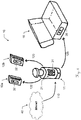
- FIG. 1 shows a first exemplary embodiment of a data distribution system for a group 10 of electronic devices.
- these comprise a laser beam projection device 11 used in the construction industry, as well as two identical laser beam receiving devices 12a, 12b cooperating therewith.
- Each of the devices 11, 12a, 12b has a display unit 31, 32, which may be configured, for example, as an LCD display, touchscreen or e-paper.
- Various product information can be displayed on these ads. This includes, but is not limited to, a product name, serial, customer or lease number, return date and location, as well as selected, ie unlocked, features of the device. This feature reduces errors e.g. B. in the issue or return of rental equipment or the correct configuration of the devices according to customer requirements.
- a computer 41 transmits data to the group to be displayed on each of the devices of the group.
- a first device in this case the projection device 11, has a first communication unit 21 with a display unit 31.
- the data is transmitted by the computer 41 only to this first communication unit 21 (arrow 110).
- the data is revised, for example, decrypted and compared with already stored data. Subsequently, they are displayed on the display unit 31 and then forwarded to the other devices 12a, b (arrow 120), z. B. by radio or near field communication, where they are then displayed on the display units 32 also.
- a tenant of the illustrated device group 10 from laser beam projection device 11 and two receiving devices 12a, 12b acquires new functions (licenses) for the rented devices by means of a software installed on his PC 41.
- the software loads the corresponding licenses via the Internet to the PC 41 and then transmits them to the communication unit 21 of the laser beam projection device 11 - for example by means of WLAN or Bluetooth and preferably encrypted.
- the communication unit 21 receives the data, it is decrypted and evaluated, and the desired functions of the laser beam projection device 11 are unlocked.
- the receiving devices 12a connects to the projection device 11, its communication unit 21 checks the configuration stored in the communication unit of this receiving device 12a and updates it.
- the display unit 32 displays updated data according to the new configuration.
- the updated information may include not only the functions but also static information such as a product name or a serial number, as well as rental contract relevant data (eg agreed return location and date or the tenant name), group related data (eg the designations or serial numbers of the rented together Devices) or maintenance-relevant data (eg the next maintenance date or a battery level).
- rental contract relevant data eg agreed return location and date or the tenant name
- group related data eg the designations or serial numbers of the rented together Devices
- maintenance-relevant data eg the next maintenance date or a battery level
- the data can also be displayed only on individual devices of the group.
- the group 10 may include a dedicated input and output device configured to be held or carried by a user and having a communication unit with display unit, and input means for the user such as a keypad or a touchscreen Display unit.
- a dedicated input and output device configured to be held or carried by a user and having a communication unit with display unit, and input means for the user such as a keypad or a touchscreen Display unit.
- Such a device may in particular be designed as a wearable, z.
- a smartwatch, VR glasses or E-garment or as a smartphone or hand-held rangefinder.
- FIG. 2 shows a second exemplary embodiment of the data distribution system.
- the external data is transmitted from the Internet to the communication unit 21 110, for example via a WLAN network or a mobile radio network, and as in FIG. 1 described to the other devices 12a, b forwarded 120.
- the device group 10 here additionally comprises a protective container 15.
- a protective container has a display unit 35 on its outer shell.
- the first communication unit 21 can transmit the data to the protective container 15 for display on this display unit 35 125. This can be done, for example, by means of near-field communication when the projection device 11 is located in the protective container 15. Also, further data from devices located in the protective container 15 can be transmitted to the latter and can thus be displayed to the user even when the container 15 is closed on the display unit 35.
- FIGS. 3a and 3b show purely by way of example and schematically two cooperating communication units 21,22.
- It shows FIG. 3a a first communication unit 21 of the first device 11 from the FIGS. 1 and 2 ,
- This has a display unit 31, which may be configured for example as an LCD display, touch screen or e-ink display and is configured to display data to a user of the device.
- the unit 21 also has a Receiving unit 51 for receiving external data.
- the receiving unit 51 is configured as a mobile radio receiving unit with a SIM card for receiving the data via a mobile radio network.
- the data thus received are forwarded to a computing unit 52 in which the external data is converted into internal data.
- the arithmetic unit 52 has a circuit and an algorithm that are configured to generate configuration data as internal data based on the external data, for example, the external data is decrypted, decompressed, reformatted and / or compared with locally stored data and merged ,
- a memory unit 53 of the communication unit 21 for example a memory module or a semiconductor drive, both local data and the external and converted data can be stored.
- the communication unit 21 has a near field communication device 54, which is designed to exchange data with corresponding devices of other communication units.
- the configuration data can be transmitted to other communication units in this way.
- FIG. 3b shows such a second communication unit 22.
- This comprises a near-field communication device 54 'configured to receive data from the corresponding device 54 of the communication unit 21 FIG. 3a , and a display unit 32 for displaying information based on the received data.
- communication unit 21 has the illustrated here neither a receiving unit nor a computing unit. Also, the memory unit 53 'may be made smaller here, why this communication unit 22 is dimensioned much smaller and also fits on or in accordance with smaller devices space.
- communication devices may be provided which are designed for the exchange of data by means of radio, for example by means of Zigbee, Z-Wave or Bluetooth.
- FIG. 4 shows a third exemplary embodiment of the data distribution system.
- the external data are transmitted via the Internet 40 via a mobile radio network (mobile radio system 43) (arrow 111), in contrast to the embodiments FIG. 1 and FIG. 2 but not to the projection device 11, but to the laser beam receiving device 12a, which has a communication unit 23 with mobile radio receiving unit.
- this communication unit 23 does not have a computing unit in this example, but instead is provided in the communication unit 22 of the projection device 11.
- the unprocessed data are therefore first forwarded to this communication unit 22 (arrow 112).
- There the data is revised and as in FIG. 1 and 2 described to the other devices 12a, b and the protective container 15 forwarded (arrows 120, 125).
- the communication unit 23 of this communication unit loads the corresponding licenses via a cellular connection and the Internet on the receiving device 12a and then transmits it to the communication unit 21 of the laser beam projection device 11 - for example by radio or near field communication.
- the communication unit 21 receives the data, it is decrypted and evaluated, and the desired functions of the laser beam projection device 11 are unlocked.
- the receiving device 12a, 12b As soon as one of the receiving devices 12a, 12b connects to the projection device 11 (receiving device 12a is usually still connected), its communication unit 21 checks the configuration stored in the communication unit of this receiving device 12a and updates it. The display unit 32 then displays updated data according to the new configuration.
- the protective container 15 with the projection device 11, or their communication units, are connected to each other, the deposited configuration is checked and updated here. Also, the display unit 35 of the protective container 15 then displays the updated data.
- the connection of the projection device 11 with the protective container 15 can be done both manually and automatically.
- FIG. 5 shows a fourth exemplary embodiment of the data distribution system.
- the external data transmitted via the Internet and a mobile network (mobile radio 43) (arrow 111), in contrast to the embodiments of FIG. 4 but not to the laser beam receiving device 12a, but to the protective container 15 which has a communication unit with a mobile radio receiving unit.
- the unprocessed data are also forwarded here to the communication unit 22 of the projection device 11 (arrow 115), there processed and then forwarded to the other devices 12a, b and the protective container 15 (arrows 120, 125).
- the protective container 15, a communication unit with the in FIG. 3a have shown functions.
- FIGS. 6 to 8 By means of flowcharts, various exemplary embodiments of a method according to the invention are illustrated.
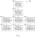
- FIG. 6 shows a first exemplary embodiment of the method.
- this method 100 is started by a user of a group of devices performing a function that requires updating data on the devices. For example, it can unlock new features for a group of rented devices - either by software on a PC or directly on one of the devices.
- this information may include license keys to unlock features in the devices.
- the data is transmitted as soon as the communication unit is ready to receive.
- the next step 113 is the necessary decryption of the external data in the communication unit.
- the external data in the communication unit is converted as far as necessary into internal configuration data that can be evaluated by the devices.
- the configuration data can then be used, for example, directly to the desired functions in the unlock the first device.
- the configuration data or information based thereon is displayed in step 131 on a display unit of the communication unit.
- the configuration data is transmitted in step 120 to the respective communication units.
- the communication units each having an RFID module.
- this or information based thereon is displayed in step 131, 132 on a display unit of the respective communication unit. For example, they are also used to unlock the desired functions in the other devices.
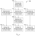
- FIG. 7 shows a second exemplary embodiment of the method.
- the external data is not sent to the first device but to a second one. From this, the data is forwarded to the first in step 112, where it is as in FIG. 6 described decrypted (step 113) and used to generate the configuration data (step 114). Among other things, the configuration data is then transferred again from the first device to the second device (step 120).
- FIG. 8 shows a third exemplary embodiment of the method. Unlike the in FIG. 6 shown here is the first device in a protective container located.
- the data necessary for updating data is transmitted to the communication unit of the first device, where in step 114, the configuration data is generated. Since the first device is located in the protective container, although information based on the configuration data can be displayed on the device itself, it is only visible to the user after the container has been opened.
- the configuration data are therefore transmitted in the next step 125 to a communication unit of the protective container, in particular by means of near-field communication, so that the information is displayed in step 135 on a display unit of the protective container.
- the configuration data are also transmitted to the other devices in step 120.
- the data may be transmitted via an external communication unit of the protective container and then displayed on the second and third devices (steps 132, 133). If the other devices are also in the protective container, the data can also be transmitted directly by means of near-field communication from the communication unit of the first device. Additionally or alternatively to the display on the devices, which is not visible in the interior of the container for the user, the data for display on the display unit of the protective container can be transmitted to this.
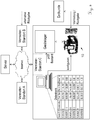
- FIG. 9 schematically illustrates an application example of an embodiment of the inventive method and system. Shown is the infrastructure of a landlord with multiple sites A, B and C. Each of the sites is connected to a server via the Internet and can access its data. This can either be a server of the landlord or belong for example to the manufacturer or distributor of the equipment to be rented.
- an end customer leases a group 10 of equipment present in the warehouse at location C and orders a particular configuration. This is entered into a database of a local personal computer, after which the license keys corresponding to the rented devices and the ordered configuration are retrieved from the server via the Internet. Then the devices of group 10 are configured, i. H. the license keys and possibly further configuration data are transmitted to the devices. This is done, as described above, preferably by transmitting the data to the communication unit of a main unit.
- the further configuration data include, in particular rent-relevant data, such as tenants, landlords, rental period and rented device group 10 (eg, number and identity of all devices of the group).
- rent-relevant data such as tenants, landlords, rental period and rented device group 10 (eg, number and identity of all devices of the group).
- the devices When the device is handed over to the customer, the devices already display information that corresponds to the configuration data, so that the risk of errors is significantly reduced.
- the configuration data can also be updated locally (eg via a mobile radio connection), for example if further functions of the devices are to be activated or the lease term is to be extended.
- the return is again at location C or at another location of the landlord.
- the information displayed on the equipment significantly reduces the risk of error even when returning it.
- At least one of the communication units of the group is configured to acquire usage data of at least one device of the group. These may include, for example, acceleration or localization data of the devices, as well as usage times and functionalities used.
- the corresponding communication unit also has an algorithm that is designed to create a usage profile based on recorded usage data and, based on this, automatically suggests the user suitable functions for the user, which can then be activated directly by the user.
- a proposal for unlockable functions can be presented in particular on one of the display devices. This saves time and prevents unnecessary replacement of equipment.
- the algorithm may be designed to find out if a device of the group already has or supports some functionality. If the user at a construction site requires a certain functionality that a device that is available to him does not provide, a location of another device providing the function can be displayed on the display unit on the same construction site by means of this algorithm. For example, the user has an older device that does not support a certain new feature. The user can then identify on the job site possible functions of other devices (eg by means of a map on the display) where a device with the appropriate functions is available on the device that the user has available (ie in particular straight into holding the hand), or the associated device group, are not available. For example, he can then automatically make a reservation of the required device, or the device group.
- the algorithms can be provided wholly or partly externally, in particular on a server or in a cloud, the data being transmitted by means of the receiving unit, for example via the Internet.
Abstract
Description
- Die vorliegende Erfindung betrifft ein System und Verfahren zum Verteilen von Daten für eine Gruppe von mindestens zwei elektronischen Geräten, insbesondere Mietgeräten.
- Bei den Mietgeräten handelt es sich insbesondere um solche Geräte, die beim Bau von Gebäuden oder anderen Strukturen zum Einsatz kommen, beispielsweise im Rahmen von Messaufgaben im Bereich der Bauinstallation. Dies umfasst sowohl Geräte zur optischen Abstandsmessung oder zur Erfassung von dreidimensionalen Koordinaten entfernter Objekte wie Theodoliten, Tachymeter, Totalstationen, Lasertracker, Laserscanner oder handgehaltene Entfernungsmessgeräte, als auch Rotations-, Kanalbau- oder Linienlaser oder Kabeldetektoren.
- Solche für professionelle Anwendungen gedachten, insbesondere hochpräzisen Geräte sind relativ teuer in der Anschaffung. Es ist folglich wünschenswert, wertvolle Vermessungsgeräte nicht zu kaufen sondern statt dessen für begrenzte Zeiträume, in denen sie benötigt werden, zu mieten.
- In der Regel werden mehrere gleiche oder verschiedene Geräte gleichzeitig und für denselben Zeitraum angemietet, insbesondere dann, wenn es sich um zusammenwirkende Geräte handelt. Zusammenwirkende Geräte können beispielsweise ein Laserstrahl-Projektionsgerät und ein oder mehrere Empfängergeräte für den projizierten Laserstrahl darstellen, wie z. B. in der
EP 2 741 049 A1 beschrieben. - Häufig weisen die genannten Geräte ausserdem eine Vielzahl von Funktionen auf, die einzeln freischaltbar bzw. sperrbar sind, sodass dasselbe Gerät zu unterschiedlichen Preisen vermietet werden kann, je nachdem welche und wie viele seiner Funktionen für den jeweiligen Kunden freigeschaltet werden sollen.
- Bei einer Vielzahl von zu vermietenden Geräten ist das Aktualisieren mietvertragrelevanter Daten in den einzelnen Mietgeräten, also beispielsweise der bereitgestellten Konfiguration, oder die korrekte Verteilung von Lizenzschlüsseln eine arbeitsintensive und fehleranfällige Aufgabe. Es ist daher wünschenswert, eine Vermietung dieser Geräte für Mieter wie Vermieter zu vereinfachen.
- Insbesondere ist es wünschenswert, dass mietvertragsrelevante Informationen, wie z. B. eine Vertragsnummer, ein festgelegtes Rückgabedatum oder die gewählte Konfiguration, auf jedem der Geräte angezeigt werden, um Ausgabe und Rücknahme der Geräte für den Vermieter, sowie Verwendung und Rückgabe für den Mieter einfacher zu gestalten. Weiterhin wäre es für den Vermieter vorteilhaft, wenn die Geräte nötige Wartungstermine selbständig anzeigen würden.
- Vorteilhaft wäre daher ein System bzw. Verfahren, das ein einfaches Verteilen von Daten in einer Gruppe von elektronischen Geräten erlaubt, sowie die so verteilten Daten auf den Geräten für einen Benutzer darzustellen.
- Bekannte Konzepte sind für sich genommen jedoch nicht dafür konzipiert, die nötigen Merkmale bereitzustellen.
- Für Mietgeschäfte können bislang herkömmliche Etiketten verwendet werden. Für einen Vermieter wäre es aber äusserst aufwendig, die vermieteten Geräte für jedes Mietgeschäft jeweils neu mit herkömmlichen Etiketten zu kennzeichnen. Eine elektronische Lösung mit automatisierten Etiketten, bei welcher der Vermieter die Informationen nicht händisch aktualisieren muss, wenn sie an einen Endkunden ausgegeben werden, wäre daher aufgrund der möglichen wesentlichen Zeitersparnis vorteilhaft.
- Aus dem Stand der Technik sind sogenannte Smart Labels bekannt, die einen passiven RFID-Transponder umfassen und beispielsweise samt Antenne auf eine Folie aufgebracht werden, die auf ein Produkt geklebt wird. Die Daten aktuell zu halten, ist mit diesen Lösungen jedoch nicht nur sehr aufwendig, sondern es ist nachteilig auch keine Datenaktualisierung mehr möglich, während die Geräte bereits beim Kunden sind.
- Weiterhin ist der Einsatz elektronischer Etiketten, sogenannter E-Label, beispielsweise zur Preisauszeichnung am Warenregal bekannt. Die E-Labels sind zentral aktualisierbar und zeigen dann den aktuellen Preis für die jeweils ausgezeichneten im Regal befindlichen Produkte an. Das Anbringen solcher E-Label an beweglichen Objekten ist jedoch problematisch. Wenn die E-Label zentral auch aus der Ferne aktualisierbar sollen, benötigen sie jeweils entsprechende Mobilfunkeinheiten zum Empfang der Daten, sowie Rechenkapazität zum Entschlüsseln und ggf. Auswerten der Daten. Dadurch werden die E-Label nicht nur relativ gross und schwer sondern verbrauchen auch viel elektrische Energie. Gerade bei relativ kleinen handhaltbaren Geräten wäre dies sehr nachteilig.
- Es ist daher eine Aufgabe der vorliegenden Erfindung, ein verbessertes System und Verfahren zum Verteilen von Daten in einer Gruppe von elektronischen Geräten bereitzustellen.
- Eine weitere Aufgabe ist es, die so verteilten Daten auf den Geräten darstellbar zu machen.
- Eine weitere Aufgabe ist es, die zu verteilenden Daten der Gruppe aus der Ferne zu übermitteln, beispielsweise über eine Internet-Verbindung.
- Eine weitere Aufgabe ist es, eine Vollständigkeitsprüfung der Geräte der Gruppe zu erleichtern.
- Eine weitere Aufgabe ist es, ein solches System und Verfahren bereitzustellen, mit welchem ein Vermieten der Gruppe von Geräten erleichtert wird, insbesondere wobei ein Zeitaufwand zum Rekonfigurieren reduziert wird.
- Eine weitere Aufgabe ist es, die Arbeitseffizienz zu erhöhen, insbesondere dadurch dass die Gefahr reduziert wird, dass falsche oder falsch konfigurierte Geräte ausgegeben und eingesetzt werden.
- Eine weitere Aufgabe ist es, ein solches System zu geringen Kosten und mit geringem konstruktivem Aufwand bereitzustellen.
- Eine weitere Aufgabe ist es, ein solches System bereitzustellen, dass auch bei kleinen Geräten und Geräten mit geringer Speicher- und Rechenleitsung anwendbar ist, insbesondere die Funktionsfähigkeit dieser Geräte nicht beeinträchtigt, und handgehaltene Geräte nicht unhandlich macht.
- Mindestens eine dieser Aufgaben wird durch die Verwirklichung der kennzeichnenden Merkmale der unabhängigen Ansprüche gelöst. Vorteilhafte Ausgestaltungen der Erfindung finden sich dabei in den jeweils abhängigen Ansprüchen.
- Ein erster Aspekt der vorliegenden Erfindung betrifft ein System zum Verteilen von Daten für eine Gruppe von mindestens zwei elektronischen Geräten, wobei jedes der Geräte eine elektronische Kommunikationseinheit aufweist, wobei die Kommunikationseinheiten jeweils dazu ausgestaltet sind, untereinander interne Daten auszutauschen.
- Gemäss diesem Aspekt der Erfindung weist jeweils mindestens eine der Kommunikationseinheiten eine Empfangseinheit auf, die zum Empfangen externer Daten von einer externen Computereinheit ausgestaltet ist. Jeweils mindestens eine der Kommunikationseinheiten - entweder dieselbe, die auch die Empfangseinheit aufweist oder eine andere - weist eine Recheneinheit mit einem Algorithmus auf, wobei der Algorithmus dazu ausgestaltet ist, basierend auf den externen Daten Konfigurationsdaten als interne Daten zu generieren, und ist dazu ausgestaltet, die Konfigurationsdaten an mindestens eine andere Kommunikationseinheit des Systems zu übermitteln. Jeweils mindestens eine der Kommunikationseinheiten weist ausserdem eine digitale Anzeigevorrichtung zur visuellen Anzeige von Informationen für einen Benutzer auf, wobei die mindestens eine Anzeigevorrichtung dazu ausgestaltet ist, basierend auf den Konfigurationsdaten aktualisierte Informationen anzuzeigen.
- Gemäss einer Ausführungsform des Systems sind die Kommunikationseinheiten dazu ausgestaltet, die internen Daten mittels Nahfeldkommunikation untereinander auszutauschen, insbesondere wobei jede der Kommunikationseinheiten ein RFID-Modul aufweist.
- Alternativ können die Kommunikationseinheiten dazu ausgestaltet sein, die internen Daten mittels einer Funkverbindung, beispielsweise Bluetooth oder Zigbee, untereinander auszutauschen.
- Gemäss einer weiteren Ausführungsform ist die Empfangseinheit als eine Mobilfunk-Empfangseinheit zum Empfangen der externen Daten über ein Mobilfunknetz ausgestaltet.
- Gemäss einer anderen Ausführungsform ist die Empfangseinheit als eine LPN-Empfangseinheit (LPN = Low Power Network) zum Empfangen der externen Daten über ein Niedrigenergienetzwerk, insbesondere LoRa oder SigFox, ausgestaltet.
- Gemäss einer anderen Ausführungsform ist die Empfangseinheit dazu ausgestaltet, Anfragen der externen Computereinheit zu erfassen.
- Gemäss einer weiteren Ausführungsform weisen die externen Daten einen oder mehrere Lizenzschlüssel für die mindestens zwei elektronischen Geräte auf.
- Gemäss einer anderen Ausführungsform sind die externen Daten verschlüsselt, und die Recheneinheit weist einen Algorithmus auf, der dazu ausgestaltet ist, die externen Daten zu entschlüsseln.
- In einer Ausführungsform des Systems sind die mindestens zwei elektronischen Geräte dazu bestimmt, im Einsatz gemeinsam verwendet zu werden, insbesondere operativ zusammenzuwirken.
- In einer Ausführungsform des Systems weist mindestens eine der Kommunikationseinheiten eine Steuerungseinheit auf, die zur Steuerung des entsprechenden elektronischen Gerätes basierend auf den Konfigurationsdaten ausgestaltet ist. Die Steuerung umfasst dabei insbesondere ein Zuschalten oder Abschalten von Funktionen des Gerätes.
- Gemäss einer weiteren Ausführungsform weist eine der Kommunikationseinheiten sowohl die Empfangseinheit als auch die Recheneinheit auf und ist dazu ausgestaltet, die Aktualisierungsdaten an die mindestens eine andere Kommunikationseinheit zu übermitteln.
- Gemäss einer anderen Ausführungsform weist eine erste Kommunikationseinheit die Empfangseinheit auf, und eine zweite Kommunikationseinheit weist die Recheneinheit auf und ist dazu ausgestaltet, die Aktualisierungsdaten mindestens an die erste Kommunikationseinheit zu übermitteln, wobei die erste Kommunikationseinheit dazu ausgestaltet ist, die externen Daten an die zweite Kommunikationseinheit zu übermitteln.
- Gemäss einer weiteren Ausführungsform ist mindestens eine der Kommunikationseinheiten dazu ausgestaltet, in definierten Intervallen Nutzungsdaten mindestens eines Gerätes der Gruppe zu erfassen, insbesondere einer Vielzahl von Geräten bzw. allen Geräten der Gruppe.
- In einer Ausführungsform weist die entsprechende Kommunikationseinheit dabei einen Algorithmus auf, der dazu ausgestaltet ist, aus den Nutzungsdaten ein Nutzungsprofil des Gerätes oder der Gruppe von Geräten zu erstellen und basierend auf dem Nutzungsprofil einem Benutzer einen Vorschlag für freischaltbare Funktionen für das mindestens eine Gerät auf einer Anzeigevorrichtung zu präsentieren. Alternativ kann der entsprechende Algorithmus auch extern auf einem Server bzw. in einer Cloud bereitgestellt sein, wobei die Kommunikationseinheit dem Algorithmus die Nutzungsdaten bereitstellt. Im Gegenzug kann die Kommunikationseinheit das Nutzungsprofil und/oder den Vorschlag für freischaltbare Funktionen erhalten, um letzteren einem Benutzer auf der Anzeigevorrichtung zu präsentieren.
- Gemäss einer weiteren Ausführungsform umfassen die internen Daten Wartungsdaten mit Informationen über einen Wartungstermin mindestens eines Gerätes der Gruppe, und die Anzeigevorrichtung des mindestens einen Gerätes ist dazu ausgestaltet, den Wartungstermin anzuzeigen.
- In einer Ausführungsform weist mindestens eine der Kommunikationseinheiten eine Statistikeinheit mit einem Algorithmus auf, der dazu ausgestaltet ist, den Wartungstermin mindestens eines Gerätes der Gruppe basierend auf Nutzungsdaten des mindestens einen Gerätes zu berechnen.
- In einer anderen Ausführungsform ist mindestens eine der Kommunikationseinheiten zum Versenden von Nutzungsdaten des mindestens einen Gerätes an die externe Computereinheit ausgestaltet, die externen Daten Informationen über den Wartungstermin umfassen, und der Algorithmus der Recheneinheit ist dazu ausgestaltet, die Wartungsdaten basierend auf den externen Daten zu generieren.
- Gemäss einer weiteren Ausführungsform weist mindestens eine der Kommunikationseinheiten einen Datenspeicher auf und ist dazu ausgestaltet, Informationen über Geräte der Gruppe zu erfassen oder abzurufen, erfasste oder abgerufene Informationen in dem Datenspeicher abzuspeichern, und die Informationen einem Benutzer auf der Anzeigevorrichtung anzuzeigen. Die Informationen über ein Gerät umfassen beispielsweise Informationen über einen Ort, freigeschaltete Funktionen und/oder einen Batteriestand des Gerätes.
- Gemäss einer weiteren Ausführungsform ist mindestens eine der Kommunikationseinheiten dazu ausgestaltet, zu erfassen, an welche anderen Kommunikationseinheiten aktuelle Konfigurationsdaten bereits übermittelt wurden, und einem Benutzer auf der Anzeigevorrichtung anzuzeigen, an die Kommunikationseinheiten welcher Geräte die aktuellen Konfigurationsdaten noch zu übermitteln sind.
- Gemäss einer weiteren Ausführungsform ist mindestens eines der Geräte der Gruppe ein Laserstrahl-Projektionsgerät, beispielsweise ein Rotationslaser, Kanalbaulaser oder Linienlaser. Insbesondere ist dabei mindestens ein weiteres der Geräte zum Empfangen eines Laserstrahls des Laserstrahl-Projektionsgerätes ausgestaltet.
- Gemäss einer weiteren Ausführungsform umfasst die Gruppe mindestens einen Schutzbehälter, der einen Innenraum aufweist, der zur Aufnahme für mindestens eines der elektronischen Geräte ausgestaltet ist. Der Schutzbehälter weist ebenfalls eine digitale Anzeigevorrichtung und eine Kommunikationseinheit auf. Dabei ist die Anzeigevorrichtung auf einer Aussenhülle des Schutzbehälters vorgesehen, und die Kommunikationseinheit des Schutzbehälters ist als eine Innenraum-Kommunikationseinheit zur Kommunikation mit Kommunikationseinheiten von im Innenraum befindlichen elektronischen Geräten ausgestaltet.
- Ein zweiter Aspekt der vorliegenden Erfindung betrifft ein Verfahren zum Aktualisieren von Daten einer Gruppe von mindestens zwei elektronischen Geräten, wobei jedes der Geräte eine elektronische Kommunikationseinheit aufweist, und die Kommunikationseinheiten jeweils dazu ausgestaltet sind, untereinander interne Daten auszutauschen. Das Verfahren umfasst
- ein Empfangen von externen Daten von einer externen Computereinheit durch eine Empfangseinheit einer der Kommunikationseinheiten;
- ein Generieren, basierend auf den externen Daten, von Konfigurationsdaten als interne Daten durch einen Algorithmus einer Recheneinheit einer der Kommunikationseinheiten;
- ein Übermitteln der Konfigurationsdaten an mindestens eine andere Kommunikationseinheit des Systems; und
- ein Anzeigen von basierend auf den Konfigurationsdaten aktualisierten Informationen auf einer Anzeigevorrichtung mindestens einer der Kommunikationseinheiten.
- Gemäss einer Ausführungsform umfasst das Verfahren ferner ein Entschlüsseln verschlüsselt übertragener externer Daten durch einen Algorithmus der Recheneinheit.
- Gemäss einer weiteren Ausführungsform umfasst das Verfahren ausserdem ein - zumindest teilweises - Steuern mindestens eines elektronischen Gerätes der Gruppe durch die entsprechende Kommunikationseinheit basierend auf den Konfigurationsdaten, insbesondere wobei dieses Steuern mindestens ein Zuschalten oder Abschalten von Funktionen des Gerätes umfasst.
- Das erfindungsgemässe System und das erfindungsgemässe Verfahren werden nachfolgend anhand von in den Zeichnungen schematisch dargestellten konkreten Ausführungsbeispielen rein beispielhaft näher beschrieben, wobei auch auf weitere Vorteile der Erfindung eingegangen wird. Im Einzelnen zeigen:
- Fig. 1
- eine erste beispielhafte Ausführungsform eines Datenverteilungssystems für eine Gruppe von Mietgeräten;
- Fig. 2
- eine zweite beispielhafte Ausführungsform eines Datenverteilungssystems für eine Gruppe von Mietgeräten;
- Fig. 3a-b
- beispielhafte Ausführungsformen einer ersten und einer zweiten Kommunikationseinheit;
- Fig. 4
- eine dritte beispielhafte Ausführungsform eines Datenverteilungssystems für eine Gruppe von Mietgeräten;
- Fig. 5
- eine vierte beispielhafte Ausführungsform eines Datenverteilungssystems für eine Gruppe von Mietgeräten;
- Fig. 6
- ein Flussdiagramm zur Illustration einer ersten beispielhaften Ausführungsform eines Datenverteilungsverfahrens;
- Fig. 7
- ein Flussdiagramm zur Illustration einer zweiten beispielhaften Ausführungsform eines Datenverteilungsverfahrens;
- Fig. 8
- ein Flussdiagramm zur Illustration einer dritten beispielhaften Ausführungsform eines Datenverteilungsverfahrens; und
- Fig. 9
- illustriert anhand eines Anwendungsbeispiels einen serverseitigen Anteil einer beispielhaften Ausführungsform eines Datenverteilungsverfahrens.
-
Figur 1 zeigt eine erste beispielhafte Ausführungsform eines Datenverteilungssystems für eine Gruppe 10 von elektronischen Geräten. Diese umfassen in dem dargestellten Beispiel ein im Konstruktionswesen eingesetztes Laserstrahl-Projektionsgerät 11, sowie zwei gleiche mit diesem zusammenwirkende Laserstrahl-Empfangsgeräte 12a, 12b. - Jedes der Geräte 11, 12a, 12b weist eine Anzeigeeinheit 31, 32 auf, die beispielsweise als LCD-Display, Touchscreen oder E-Papier ausgestaltet sein kann. Verschiedene Produktinformationen sind auf diesen Anzeigen darstellbar. Dies umfasst unter anderem eine Produktbezeichnung, Serien-, Kunden- oder, Mietvertragsnummer, Rückgabedatum und -ort, sowie gewählte, d. h. freigeschaltete, Funktionen des Gerätes. Dieses Merkmal verringert Irrtümer z. B. bei der Aus- oder Rückgabe von Mietgeräten oder der korrekten Konfiguration der Geräte gemäss den Kundenwünschen.
- Von einem Computer 41 werden Daten an die Gruppe übermittelt, die auf jedem der Geräte der Gruppe angezeigt werden sollen.
- Erfindungsgemäss werden diese Daten nicht an jedes einzelne Gerät übermittelt. Wie in
Figur 1 dargestellt, weist ein erstes Gerät, hier das Projektionsgerät 11, eine erste Kommunikationseinheit 21 auf mit einer Anzeigeeinheit 31. Die Daten werden von dem Computer 41 nur an diese erste Kommunikationseinheit 21 übertragen (Pfeil 110). Von der ersten Kommunikationseinheit 21 werden die Daten überarbeitet, beispielsweise entschlüsselt und mit bereits gespeicherten Daten abgeglichen. Anschliessend werden sie auf der Anzeigeeinheit 31 angezeigt und dann an die anderen Geräte 12a,b weitergeleitet (Pfeil 120), z. B. mittels Funk oder Nahfeldkommunikation, wo sie dann auf deren Anzeigeeinheiten 32 ebenfalls angezeigt werden. - In der Praxis funktioniert die Datenverteilung gemäss
Figur 1 beispielsweise folgendermassen: Ein Mieter der dargestellten Gerätegruppe 10 aus Laserstrahl-Projektionsgerät 11 und zwei Empfangsgeräten 12a, 12b erwirbt neue Funktionen (Lizenzen) für die gemieteten Geräte mittels einer auf seinem PC 41 installierten Software. Die Software lädt die entsprechenden Lizenzen über das Internet auf den PC 41 und überträgt sie dann an die Kommunikationseinheit 21 des Laserstrahl-Projektionsgerätes 11 - beispielsweise mittels WLAN oder Bluetooth und vorzugsweise verschlüsselt. Sobald die Kommunikationseinheit 21 die Daten erhält, werden diese entschlüsselt und ausgewertet, und die gewünschten Funktionen des Laserstrahl-Projektionsgerätes 11 werden freigeschaltet. Sobald eines der Empfangsgeräte 12a sich mit dem Projektionsgerät 11 verbindet, prüft dessen Kommunikationseinheit 21 die in der Kommunikationseinheit dieses Empfangsgerätes 12a hinterlegte Konfiguration und aktualisiert diese. Auf der Anzeigeeinheit 32 werden dann entsprechend der neuen Konfiguration aktualisierte Daten angezeigt. - Diese Datenverteilung findet jedes Mal statt, wenn die Konfiguration geändert werden soll. Dadurch werden die dargestellten Informationen dynamisch aktuell gehalten und ändern sich, sobald Funktionen aktiviert oder deaktiviert werden. Die aktualisierten Informationen können neben den Funktionen auch statische Informationen wie eine Produktbezeichnung oder eine Seriennummer umfassen, sowie mietvertragsrelevante Daten (z. B. vereinbarten Rückgabeort und -datum oder den Mieternamen), gruppenbezogene Daten (z. B. die Bezeichnungen oder Seriennummern der zusammen vermieteten Geräte) oder wartungsrelevante Daten (z. B. den nächsten Wartungstermin oder einen Batteriestand).
- Alle oder ein Teil dieser Informationen werden in der entsprechenden Gruppe 10 von Geräten verteilt, sodass auf allen Geräten einheitliche Daten angezeigt werden können.
- Alternativ können die Daten auch nur auf einzelnen Geräten der Gruppe anzeigbar sein. Auch kann die Gruppe 10 ein spezielles Ein- und Ausgabegerät aufweisen, dass dazu ausgestaltet ist, von einem Benutzer gehalten oder getragen zu werden, und eine Kommunikationseinheit mit Anzeigeeinheit aufweist, sowie Eingabemittel für den Benutzer, wie ein Tastenfeld oder eine als Touchscreen ausgebildete Anzeigeeinheit. Ein solches Gerät kann insbesondere als Wearable ausgestaltet sein, z. B. als eine Smartwatch, VR-Brille oder ein E-Kleidungsstück, oder als ein Smartphone oder handhaltbarer Entfernungsmesser.
-
Figur 2 zeigt eine zweite beispielhafte Ausführungsform des Datenverteilungssystems. Dabei werden die externen Daten aus dem Internet an die Kommunikationseinheit 21 übertragen 110, beispielsweise über ein WLAN-Netzwerk oder ein Mobilfunknetz, und wie inFigur 1 beschrieben an die anderen Geräte 12a,b weitergeleitet 120. - Die Geräte-Gruppe 10 umfasst hier zusätzlich einen Schutzbehälter 15. Verschiedene auch hier mögliche Ausgestaltungen eines solchen Schutzbehälters sind beispielsweise in der Europäischen Patentanmeldung
15196101.8 - Die
Figuren 3a und 3b zeigen rein beispielhaft und schematisch zwei zusammenwirkende Kommunikationseinheiten 21,22. Dabei zeigtFigur 3a eine erste Kommunikationseinheit 21 des ersten Geräts 11 aus denFiguren 1 und2 . Diese weist eine Anzeigeeinheit 31 auf, die beispielsweise als LCD-Display, Touchscreen oder E-Ink-Display ausgestaltet sein kann und zur Anzeige von Daten an einen Benutzer des Geräts ausgestaltet ist. Die Einheit 21 weist ausserdem eine Empfangseinheit 51 auf zum Empfang externer Daten. Hier ist die Empfangseinheit 51 als eine Mobilfunk-Empfangseinheit ausgestaltet mit einer SIM-Karte zum Empfang der Daten über ein Mobilfunknetz. Die so empfangenen Daten werden an eine Recheneinheit 52 weitergeleitet, in der die externen Daten in interne Daten umgewandelt werden. Dazu weist die Recheneinheit 52 eine Schaltung und einen Algorithmus auf, die dazu ausgestaltet sind, basierend auf den externen Daten Konfigurationsdaten als interne Daten zu generieren, wozu beispielsweise die externen Daten entschlüsselt, dekomprimiert, umformatiert und/oder mit lokal gespeicherten Daten abgeglichen und zusammengeführt werden. In einer Speichereinheit 53 der Kommunikationseinheit 21, beispielsweise einem Speicherbaustein oder einem Halbleiterlaufwerk, sind sowohl lokale Daten, als auch die externen und umgewandelten Daten speicherbar. - Gemäss dieser Ausführungsform weist die Kommunikationseinheit 21 eine Nahfeldkommunikationsvorrichtung 54 auf, die zum Austausch von Daten mit entsprechenden Vorrichtungen anderer Kommunikationseinheiten ausgestaltet ist. Insbesondere können auf diese Weise die Konfigurationsdaten an andere Kommunikationseinheiten übermittelt werden.
-
Figur 3b zeigt eine solche zweite Kommunikationseinheit 22. Diese weist eine Nahfeldkommunikationsvorrichtung 54' auf, ausgestaltet zum Empfangen von Daten der entsprechenden Vorrichtung 54 der Kommunikationseinheit 21 ausFigur 3a , sowie eine Anzeigeeinheit 32 zum Darstellen von Informationen auf Basis der empfangenen Daten. - Im Gegensatz zur ersten, in
Figur 3a gezeigten, Kommunikationseinheit 21 weist die hier dargestellte weder eine Empfangseinheit noch eine Recheneinheit auf. Auch die Speichereinheit 53' kann hier kleiner ausgeführt sein, weshalb diese Kommunikationseinheit 22 deutlich kleiner dimensioniert ist und auch auf bzw. in entsprechend kleineren Geräten Platz findet. - Alternativ können auch Kommunikationsvorrichtungen vorgesehen sein, die zum Austausch von Daten mittels Funk ausgestaltet sind, beispielsweise mittels Zigbee, Z-Wave oder Bluetooth.
-
Figur 4 zeigt eine dritte beispielhafte Ausführungsform des Datenverteilungssystems. Dabei werden die externen Daten über das Internet 40 über ein Mobilfunknetz (Mobilfunkanlage 43) übertragen (Pfeil 111), im Gegensatz zu den Ausführungsformen ausFigur 1 undFigur 2 aber nicht an das Projektionsgerät 11, sondern an das Laserstrahl-Empfangsgerät 12a, das über eine Kommunikationseinheit 23 mit Mobilfunk-Empfangseinheit verfügt. Diese Kommunikationseinheit 23 verfügt in diesem Beispiel aber nicht über eine Recheneinheit, diese ist statt dessen in der Kommunikationseinheit 22 des Projektionsgerätes 11 vorgesehen. Die unverarbeiteten Daten werden daher zunächst an diese Kommunikationseinheit 22 weitergeleitet (Pfeil 112). Dort werden die Daten überarbeitet und wie inFigur 1 und2 beschrieben an die anderen Geräte 12a,b und den Schutzbehälter 15 weitergeleitet (Pfeile 120, 125). - In der Praxis funktioniert die Datenverteilung gemäss
Figur 4 beispielsweise folgendermassen: Ein Mieter der dargestellten Gerätegruppe 10 aus Laserstrahl-Projektionsgerät 11, zwei Empfangsgeräten 12a, 12b und Schutzbehälter 15 erwirbt neue Funktionen (Lizenzen) für die gemieteten Geräte über ein Interface der Kommunikationseinheit eines der Geräte, hier dem Empfangsgerät 12a. Die Kommunikationseinheit 23 dieser Kommunikationseinheit lädt die entsprechenden Lizenzen über eine Mobilfunkverbindung und das Internet auf das Empfangsgerät 12a und überträgt sie dann an die Kommunikationseinheit 21 des Laserstrahl-Projektionsgerätes 11 - beispielsweise mittels Funk oder Nahfeldkommunikation. Sobald die Kommunikationseinheit 21 die Daten erhält, werden diese entschlüsselt und ausgewertet, und die gewünschten Funktionen des Laserstrahl-Projektionsgerätes 11 werden freigeschaltet. Sobald eines der Empfangsgeräte 12a, 12b sich mit dem Projektionsgerät 11 verbindet (Empfangsgerät 12a ist in der Regel noch verbunden), prüft dessen Kommunikationseinheit 21 die in der Kommunikationseinheit dieses Empfangsgerätes 12a hinterlegte Konfiguration und aktualisiert diese. Auf der Anzeigeeinheit 32 werden dann entsprechend der neuen Konfiguration aktualisierte Daten angezeigt. - Wenn der Schutzbehälter 15 mit dem Projektionsgerät 11, bzw. deren Kommunikationseinheiten, miteinander verbunden werden, wird auch hier die hinterlegte Konfiguration geprüft und aktualisiert. Auch die Anzeigeeinheit 35 des Schutzbehälters 15 zeigt dann die aktualisierten Daten an. Die Verbindung des Projektionsgerätes 11 mit dem Schutzbehälter 15 kann sowohl manuell als auch automatisch erfolgen.
-
Figur 5 zeigt eine vierte beispielhafte Ausführungsform des Datenverteilungssystems. Wie inFigur 4 gezeigt werden die externen Daten über das Internet und ein Mobilfunknetz (Mobilfunkanlage 43) übertragen (Pfeil 111), im Gegensatz zu der Ausführungsformen ausFigur 4 aber nicht an das Laserstrahl-Empfangsgerät 12a, sondern an den Schutzbehälter 15 der über eine Kommunikationseinheit mit Mobilfunk-Empfangseinheit verfügt. Die unverarbeiteten Daten werden auch hier an die Kommunikationseinheit 22 des Projektionsgerätes 11 weitergeleitet (Pfeil 115), dort verarbeitet und dann an die anderen Geräte 12a,b und den Schutzbehälter 15 weitergeleitet (Pfeile 120, 125). - Alternativ kann natürlich auch der Schutzbehälter 15 eine Kommunikationseinheit mit den in
Figur 3a gezeigten Funktionen aufweisen. - In den
Figuren 6 bis 8 werden anhand von Flussdiagrammen verschiedene beispielhafte Ausgestaltungen eines erfindungsgemässen Verfahrens illustriert. -
Figur 6 zeigt eine erste beispielhafte Ausführungsform des Verfahrens. Dieses Verfahren 100 wird insbesondere dadurch gestartet, dass ein Benutzer einer Gruppe von Geräten eine Funktion ausführt, die eine Aktualisierung von Daten auf den Geräten erforderlich macht. Dazu kann er beispielsweise für eine Gruppe von gemieteten Geräten neue Funktionen freischalten - entweder mittels einer Software auf einem PC oder direkt an einem der Geräte. Dies führt zum ersten Schritt 110 des Verfahrens, in welchem die zur Aktualisierung nötigen Daten an die Kommunikationseinheit eines ersten Gerätes übermittelt werden. Diese Daten können beispielsweise Lizenzschlüssel umfassen, um die Funktionen in den Geräten freizuschalten. Die Daten werden übertragen, sobald die Kommunikationseinheit empfangsbereit ist. - Da die Daten vorzugsweise verschlüsselt versendet werden, erfolgt im nächsten Schritt 113 das notwendige Entschlüsseln der externen Daten in der Kommunikationseinheit. Im Anschluss werden im nächsten Schritt 114 die externen Daten in der Kommunikationseinheit soweit nötig umgewandelt in interne Konfigurationsdaten, die von den Geräten auswertbar sind.
- Die Konfigurationsdaten können dann beispielsweise direkt dazu verwendet werden, um die gewünschten Funktionen im ersten Gerät freizuschalten. Ausserdem werden die Konfigurationsdaten bzw. auf diesen basierende Informationen in Schritt 131 auf einer Anzeigeeinheit der Kommunikationseinheit angezeigt.
- Sobald die Kommunikationseinheit des ersten Geräts eine Verbindung mit den Kommunikationseinheiten weiterer Geräte der Gruppe aufnimmt, werden die Konfigurationsdaten in Schritt 120 an die jeweiligen Kommunikationseinheiten übermittelt. Dazu kann insbesondere Nahfeldkommunikation eingesetzt werden, wobei die Kommunikationseinheiten jeweils ein RFID-Modul aufweisen.
- Sobald eine weitere Kommunikationseinheit die Konfigurationsdaten erhalten hat, werden diese bzw. auf diesen basierende Informationen in Schritt 131, 132 auf einer Anzeigeeinheit der jeweiligen Kommunikationseinheit angezeigt. Beispielsweise werden sie ausserdem dazu verwendet, die gewünschten Funktionen auch in den weiteren Geräten freizuschalten.
-
Figur 7 zeigt eine zweite beispielhafte Ausführungsform des Verfahrens. Im Gegensatz zu dem inFigur 6 gezeigten werden in diesem Verfahren 100 in Schritt 111 die externen Daten nicht an das erste Gerät versendet, sondern an ein zweites. Von diesem werden die Daten in Schritt 112 an das erste weitergeleitet, wo sie wie inFigur 6 beschrieben entschlüsselt (Schritt 113) und zur Generierung der Konfigurationsdaten verwendet werden (Schritt 114). Von dem ersten Gerät werden die Konfigurationsdaten dann unter anderem auch wieder an das zweite Gerät übertragen (Schritt 120). -
Figur 8 zeigt eine dritte beispielhafte Ausführungsform des Verfahrens. Im Gegensatz zu dem inFigur 6 gezeigten ist hier das erste Gerät in einem Schutzbehälter befindlich. In Schritt 110 werden die zur Aktualisierung nötigen Daten an die Kommunikationseinheit des ersten Gerätes übermittelt, wo in Schritt 114 die Konfigurationsdaten generiert werden. Da das erste Gerät sich im Schutzbehälter befindet, können auf den Konfigurationsdaten basierende Informationen zwar auf dem Gerät selbst angezeigt werden, sind für den Benutzer aber erst nach Öffnen des Behälters sichtbar. Vorteilhaft werden die Konfigurationsdaten daher im nächsten Schritt 125 an eine Kommunikationseinheit des Schutzbehälters übermittelt, insbesondere mittels Nahfeldkommunikation, sodass die Informationen in Schritt 135 auf einer Anzeigeeinheit des Schutzbehälters angezeigt werden. An die weiteren Geräte werden die Konfigurationsdaten in Schritt 120 ebenfalls übermittelt. Sofern sie sich ausserhalb des Schutzbehälters befinden, können die Daten über eine externe Kommunikationseinheit des Schutzbehälters übertragen werden, und dann auf dem zweiten und dritten Gerät angezeigt werden (Schritte 132, 133). Sofern sich die anderen Geräte ebenfalls im Schutzbehälter befinden, können die Daten auch direkt mittels Nahfeldkommunikation von der Kommunikationseinheit des ersten Gerätes übertragen werden. Zusätzlich oder alternativ zur Anzeige auf den Geräten, die im Innern des Behälters für den Benutzer nicht sichtbar ist, können die Daten zur Anzeige auf der Anzeigeeinheit des Schutzbehälters an diesen übertragen werden. -
Figur 9 illustriert schematisch ein Anwendungsbeispiel für eine Ausführungsform des erfindungsgemässen Verfahrens und Systems. Gezeigt ist die Infrastruktur eines Vermieters mit mehreren Standorten A, B und C. Jeder der Standorte ist über das Internet mit einem Server verbunden und kann auf dessen Daten zugreifen. Dieser kann entweder ein Server des Vermieters selbst sein oder beispielsweise dem Hersteller oder Vertreiber der zu vermietenden Geräte gehören. - Am Standort C des Vermieters mietet ein Endkunde eine Gruppe 10 von Geräten, die im Lager des Standorts C vorhanden sind, und bestellt eine bestimmte Konfiguration. Dies wird in eine Datenbank eines örtlichen Personal Computers eingetragen, woraufhin die den gemieteten Geräten und der bestellten Konfiguration entsprechenden Lizenzschlüssel über das Internet vom Server abgerufen werden. Anschliessend werden die Geräte der Gruppe 10 konfiguriert, d. h. die Lizenzschlüssel und eventuell weitere Konfigurationsdaten werden an die Geräte übertragen. Dies erfolgt, wie oben beschrieben, vorzugsweise durch Übertragung der Daten an die Kommunikationseinheit eines Hauptgerätes.
- Die weiteren Konfigurationsdaten umfassen insbesondere mietvertragsrelevante Daten, also beispielsweise zu Mieter, Vermieter, Mietdauer und gemieteter Gerätegruppe 10 (z. B. Anzahl und Identität aller Geräte der Gruppe).
- Die Geräte zeigen bei Übergabe an den Kunden bereits den Konfigurationsdaten entsprechende Informationen an, sodass die Gefahr von Irrtümern deutlich reduziert wird.
- Der Kunde übernimmt die Geräte und nutzt sie vertragsgemäss. Wie weiter oben beschrieben, können die Konfigurationsdaten dabei auch vor Ort (z. B. über eine Mobilfunkverbindung) aktualisiert werden, beispielsweise wenn weitere Funktionen der Geräte freigeschaltet oder die Mietvertragsdauer verlängert werden sollen.
- Die Rückgabe erfolgt wieder an Standort C oder an einem anderen Standort des Vermieters. Durch die auf den Geräten angezeigten Informationen ist auch bei der Rückgabe die Gefahr von Irrtümern deutlich reduziert.
- Um das mögliche Problem zu lösen, dass ein Anwender der Gerätegruppe bestimmte Funktionalitäten der Geräte nicht kennt, obwohl diese vorhanden sind oder freigeschaltet werden könnten, ist in einer Ausführungsform des Systems mindestens eine der Kommunikationseinheiten der Gruppe dazu ausgestaltet, Nutzungsdaten mindestens eines Gerätes der Gruppe zu erfassen. Diese können beispielsweise Beschleunigungs- oder Lokalisierungsdaten der Geräte umfassen, sowie Nutzungszeiten und verwendete Funktionalitäten.
- Die entsprechende Kommunikationseinheit weist ausserdem einen Algorithmus auf, der dazu ausgestaltet ist, basierend auf erfassten Nutzungsdaten ein Nutzungsprofil zu erstellen und darauf basierend dem Anwender automatisch für diesen passende Funktionen vorschlägt, wobei diese dann vom Anwender direkt aktiviert werden können. Ein Vorschlag für freischaltbare Funktionen kann dabei insbesondere auf einer der Anzeigevorrichtungen präsentiert werden. Dies ermöglicht eine Zeitersparnis und verhindert ein unnötiges Austauschen von Geräten.
- Weiterhin kann der Algorithmus so ausgelegt sein, herauszufinden, ob ein Gerät der Gruppe eine bestimmte Funktionalität bereits aufweist oder diese unterstützt. Benötigt der Anwender auf einer Baustelle eine bestimmte Funktionalität, die ein ihm zur Verfügung stehendes Gerät nicht bereitstellt, kann mittels dieses Algorithmus auf der Anzeigeeinheit ein Standort eines anderen die Funktion bereitstellenden Gerätes auf derselben Baustelle dargestellt werden. So hat der Anwender zum Beispiel ein älteres Gerät welches eine gewisse neue Funktion nicht unterstützt. Der Anwender kann dann auf der Baustelle mögliche Funktionen anderer Geräte identifizieren (z. B. mit Hilfe einer Karte auf der Anzeige), wo ein Gerät mit den passenden Funktionen ist, welche beim Gerät, das der Anwender zur Verfügung hat (d. h. insbesondere gerade in der Hand hält), bzw. der zugehörigen Gerätegruppe, nicht verfügbar sind. Beispielsweise kann er dann automatisch eine Reservation des benötigten Gerätes, bzw. der Gerätegruppe, vornehmen.
- Alternativ können die Algorithmen ganz oder teilweise extern, insbesondere auf einem Server oder in einer Cloud, vorgesehen sein, wobei die Daten mittels der Empfangseinheit beispielsweise über das Internet übertragen werden.
- Es versteht sich, dass diese dargestellten Figuren nur mögliche Ausführungsbeispiele schematisch darstellen. Die verschiedenen Ansätze können ebenso miteinander wie mit Verfahren und Geräten des Stands der Technik kombiniert werden.
Claims (15)
- System zum Verteilen von Daten für eine Gruppe (10) von mindestens zwei elektronischen Geräten (11, 12), wobei jedes der Geräte eine elektronische Kommunikationseinheit (21, 22) aufweist, wobei die Kommunikationseinheiten (21, 22) jeweils dazu ausgestaltet sind, untereinander interne Daten auszutauschen,
dadurch gekennzeichnet, dass
jeweils mindestens eine der Kommunikationseinheiten- eine Empfangseinheit (51) aufweist, die zum Empfangen externer Daten von einer externen Computereinheit (41) ausgestaltet ist;- eine Recheneinheit (52) mit einem Algorithmus aufweist, wobei der Algorithmus dazu ausgestaltet ist, basierend auf den externen Daten Konfigurationsdaten als interne Daten zu generieren, und dazu ausgestaltet ist, die Konfigurationsdaten an mindestens eine andere Kommunikationseinheit des Systems zu übermitteln; und- eine digitale Anzeigevorrichtung (31, 32) zur visuellen Anzeige von Informationen für einen Benutzer aufweist, wobei die Anzeigevorrichtung (31, 32) dazu ausgestaltet ist, basierend auf den Konfigurationsdaten aktualisierte Informationen anzuzeigen. - System nach Anspruch 1,
dadurch gekennzeichnet, dass
die Kommunikationseinheiten (21, 22) dazu ausgestaltet sind, die internen Daten mittels Nahfeldkommunikation untereinander auszutauschen, insbesondere wobei jede der Kommunikationseinheiten (21, 22) ein RFID-Modul aufweist. - System nach Anspruch 1 oder Anspruch 2,
dadurch gekennzeichnet, dass
die Empfangseinheit (51)- als eine Mobilfunk-Empfangseinheit zum Empfangen der externen Daten über ein Mobilfunknetz ausgestaltet ist; und/oder- als eine LPN-Empfangseinheit zum Empfangen der externen Daten über ein Niedrigenergienetzwerk, insbesondere LoRa oder SigFox, ausgestaltet ist, insbesondere wobei die Empfangseinheit (51) dazu ausgestaltet ist, Anfragen der externen Computereinheit (41) zu erfassen. - System nach einem der vorangehenden Ansprüche,
dadurch gekennzeichnet, dass
die externen Daten- lizenzbezogene Daten, insbesondere Lizenzschlüssel, für die mindestens zwei elektronischen Geräte (11, 12) aufweisen; und/oder- verschlüsselt sind, und die Recheneinheit (52) einen Algorithmus aufweist, der dazu ausgestaltet ist, die externen Daten zu entschlüsseln. - System nach einem der vorangehenden Ansprüche,
dadurch gekennzeichnet, dass
mindestens eine der Kommunikationseinheiten (21, 22) eine Steuerungseinheit aufweist, die zur Steuerung des entsprechenden elektronischen Gerätes (11, 12) basierend auf den Konfigurationsdaten ausgestaltet ist, insbesondere wobei die Steuerung ein Zuschalten oder Abschalten von Funktionen des Gerätes (11, 12) umfasst. - System nach einem der vorangehenden Ansprüche,
dadurch gekennzeichnet, dass
eine der Kommunikationseinheiten sowohl die Empfangseinheit (51) als auch die Recheneinheit (52) aufweist und dazu ausgestaltet ist, die Aktualisierungsdaten an die mindestens eine andere Kommunikationseinheit zu übermitteln. - System nach einem der Ansprüche 1 bis 5,
dadurch gekennzeichnet, dass
eine erste Kommunikationseinheit die Empfangseinheit (51) aufweist, und eine zweite Kommunikationseinheit die Recheneinheit (52) aufweist und dazu ausgestaltet ist, die Aktualisierungsdaten mindestens an die erste Kommunikationseinheit zu übermitteln, wobei die erste Kommunikationseinheit dazu ausgestaltet ist, die externen Daten an die zweite Kommunikationseinheit zu übermitteln. - System nach einem der vorangehenden Ansprüche,
dadurch gekennzeichnet, dass
mindestens eine der Kommunikationseinheiten (21, 22) dazu ausgestaltet ist, in definierten Intervallen Nutzungsdaten mindestens eines Gerätes (11, 12) der Gruppe (10) zu erfassen, insbesondere wobei die entsprechende Kommunikationseinheit einen Algorithmus aufweist, der dazu ausgestaltet ist, ein Nutzungsprofil zu erstellen und basierend auf dem Nutzungsprofil einem Benutzer einen Vorschlag für freischaltbare Funktionen für das mindestens eine Gerät (11, 12) auf einer Anzeigevorrichtung (31, 32) zu präsentieren. - System nach Anspruch 8,
dadurch gekennzeichnet, dass- die internen Daten Wartungsdaten mit Informationen über einen Wartungstermin mindestens eines Gerätes (11, 12) der Gruppe (10) umfassen, und- die Anzeigevorrichtung (31, 32) des mindestens einen Gerätes (11, 12) dazu ausgestaltet ist, den Wartungstermin anzuzeigen,wobei mindestens eine der Kommunikationseinheiten (21, 22)- eine Statistikeinheit mit einem Algorithmus aufweist, der dazu ausgestaltet ist, den Wartungstermin mindestens eines Gerätes (11, 12) der Gruppe (10) basierend auf den Nutzungsdaten des mindestens einen Gerätes (11, 12) zu berechnen; oder- zum Versenden der Nutzungsdaten des mindestens einen Gerätes (11, 12) an die externe Computereinheit (41) ausgestaltet ist, die externen Daten Informationen über den Wartungstermin umfassen, und der Algorithmus der Recheneinheit (52) dazu ausgestaltet ist, die Wartungsdaten basierend auf den externen Daten zu generieren. - System nach einem der vorangehenden Ansprüche,
dadurch gekennzeichnet, dass
mindestens eine der Kommunikationseinheiten (21, 22) einen Datenspeicher (53) aufweist und dazu ausgestaltet ist,- Informationen über Geräte (11, 12) der Gruppe (10) zu erfassen oder abzurufen,- erfasste oder abgerufene Informationen in dem Datenspeicher (53) abzuspeichern, und- die Informationen einem Benutzer auf der Anzeigevorrichtung (31, 32) anzuzeigen, insbesondere wobei die Informationen über ein Gerät (11, 12) Informationen über einen Ort des Gerätes (11, 12) und freigeschaltete Funktionen des Gerätes (11, 12) umfassen. - System nach einem der vorangehenden Ansprüche,
dadurch gekennzeichnet, dass
mindestens eine der Kommunikationseinheiten (21, 22) dazu ausgestaltet ist,- zu erfassen, an welche anderen Kommunikationseinheiten (21, 22) aktuelle Konfigurationsdaten bereits übermittelt wurden; und- einem Benutzer auf der Anzeigevorrichtung (31, 32) anzuzeigen, an die Kommunikationseinheiten (21, 22) welcher Geräte (11, 12) die aktuellen Konfigurationsdaten noch zu übermitteln sind. - System nach einem der vorangehenden Ansprüche,
dadurch gekennzeichnet, dass- die mindestens zwei elektronischen Geräte (11, 12) dazu bestimmt sind, im Einsatz gemeinsam verwendet zu werden, insbesondere operativ zusammenzuwirken; und/oder- mindestens eines der Geräte (11) der Gruppe (10) ein Laserstrahl-Projektionsgerät ist, insbesondere ein Rotationslaser, Kanalbaulaser oder Linienlaser, insbesondere wobei mindestens ein weiteres der Geräte (12) zum Empfangen eines Laserstrahls des Laserstrahl-Projektionsgerätes ausgestaltet ist. - System nach einem der vorangehenden Ansprüche,
dadurch gekennzeichnet, dass
die Gruppe (10) mindestens einen Schutzbehälter (15) umfasst, der einen Innenraum aufweist, der zur Aufnahme für mindestens eines der elektronischen Geräte (11, 12) ausgestaltet ist, wobei- eine digitale Anzeigevorrichtung (35) auf einer Aussenhülle des Schutzbehälters (15) vorgesehen ist; und- eine Kommunikationseinheit des Schutzbehälters (15) als eine Innenraum-Kommunikationseinheit zur Kommunikation mit Kommunikationseinheiten (21, 22) von im Innenraum befindlichen elektronischen Geräten (11, 12) ausgestaltet ist. - Verfahren (100) zum Aktualisieren von Daten einer Gruppe (10) von mindestens zwei elektronischen Geräten (11, 12), wobei jedes der Geräte eine elektronische Kommunikationseinheit (21, 22) aufweist, und die Kommunikationseinheiten (21, 22) jeweils dazu ausgestaltet sind, untereinander interne Daten auszutauschen, mit- einem Empfangen von externen Daten von einer externen Computereinheit (41) durch eine Empfangseinheit (51) einer der Kommunikationseinheiten;- einem Generieren, basierend auf den externen Daten, von Konfigurationsdaten als interne Daten durch einen Algorithmus einer Recheneinheit (52) einer der Kommunikationseinheiten;- einem Übermitteln der Konfigurationsdaten an mindestens eine andere Kommunikationseinheit des Systems; und- einem Anzeigen von basierend auf den Konfigurationsdaten aktualisierten Informationen auf einer Anzeigevorrichtung (31, 32) mindestens einer der Kommunikationseinheiten.
- Verfahren nach Anspruch 14,
gekennzeichnet durch
ein Steuern mindestens eines elektronischen Gerätes (11, 12) der Gruppe (10) durch die entsprechende Kommunikationseinheit (21, 22) basierend auf den Konfigurationsdaten, insbesondere wobei das Steuern ein Zuschalten oder Abschalten von Funktionen des Gerätes (11, 12) umfasst.
Priority Applications (3)
| Application Number | Priority Date | Filing Date | Title |
|---|---|---|---|
| EP17167585.3A EP3392811B1 (de) | 2017-04-21 | 2017-04-21 | Datenverteilungssystem und -verfahren für eine gruppe von elektronischen geräten |
| CN201810353119.5A CN108734546B (zh) | 2017-04-21 | 2018-04-19 | 用于一组电子装置的数据分配的系统和方法 |
| US15/959,197 US11755005B2 (en) | 2017-04-21 | 2018-04-21 | Data distribution system and method for a group of electronics devices |
Applications Claiming Priority (1)
| Application Number | Priority Date | Filing Date | Title |
|---|---|---|---|
| EP17167585.3A EP3392811B1 (de) | 2017-04-21 | 2017-04-21 | Datenverteilungssystem und -verfahren für eine gruppe von elektronischen geräten |
Publications (2)
| Publication Number | Publication Date |
|---|---|
| EP3392811A1 true EP3392811A1 (de) | 2018-10-24 |
| EP3392811B1 EP3392811B1 (de) | 2021-08-18 |
Family
ID=58664492
Family Applications (1)
| Application Number | Title | Priority Date | Filing Date |
|---|---|---|---|
| EP17167585.3A Active EP3392811B1 (de) | 2017-04-21 | 2017-04-21 | Datenverteilungssystem und -verfahren für eine gruppe von elektronischen geräten |
Country Status (3)
| Country | Link |
|---|---|
| US (1) | US11755005B2 (de) |
| EP (1) | EP3392811B1 (de) |
| CN (1) | CN108734546B (de) |
Cited By (1)
| Publication number | Priority date | Publication date | Assignee | Title |
|---|---|---|---|---|
| WO2019234244A1 (en) | 2018-06-08 | 2019-12-12 | Hexagon Technology Center Gmbh | Workflow deployment |
Citations (3)
| Publication number | Priority date | Publication date | Assignee | Title |
|---|---|---|---|---|
| EP2741049A1 (de) | 2012-12-05 | 2014-06-11 | Leica Geosystems AG | Laserstrahlhorizontalitätstreue- Überprüfvorrichtung und ebensolches Verfahren |
| US20150286209A1 (en) * | 2014-04-02 | 2015-10-08 | Ridge Tool Company | Electronic tool lock |
| WO2016179271A1 (en) * | 2015-05-04 | 2016-11-10 | Milwaukee Electric Tool Corporation | Power tool and method for wireless communication |
Family Cites Families (30)
| Publication number | Priority date | Publication date | Assignee | Title |
|---|---|---|---|---|
| US6230081B1 (en) * | 1996-02-15 | 2001-05-08 | Christian Albertshofer | Information system for golf carts and system for calculation of use and/or acquisition of use data |
| JP2001160106A (ja) * | 1999-09-21 | 2001-06-12 | Olympus Optical Co Ltd | 医療機器リース方法、医療機器リースシステム及び医療機器 |
| JP4565703B2 (ja) * | 2000-05-16 | 2010-10-20 | グローリー株式会社 | データ記憶装置およびデータ記憶方法 |
| AU2003210490B2 (en) | 2002-01-11 | 2008-07-10 | Sap Aktiengesellschaft | Context-aware and real-time item tracking system architecture and scenarios |
| US7421499B1 (en) * | 2002-04-10 | 2008-09-02 | At&T Corp. | Automated adjustment of IP address lease time based on usage |
| WO2003090125A2 (en) * | 2002-04-19 | 2003-10-30 | Computer Associates Think, Inc. | Method and system for distributing data |
| JP4546967B2 (ja) * | 2003-10-22 | 2010-09-22 | ライカ ジオシステムズ アクチェンゲゼルシャフト | ワークサイト上の装置間情報交換管理方法とその装置 |
| US6845279B1 (en) * | 2004-02-06 | 2005-01-18 | Integrated Technologies, Inc. | Error proofing system for portable tools |
| US20050228877A1 (en) * | 2004-04-07 | 2005-10-13 | Arnold Monitzer | System for managing a device |
| US20060273918A1 (en) * | 2005-06-07 | 2006-12-07 | Ram Satish N | System for providing multiple maintenance profiles using wireless communications |
| WO2007139587A1 (en) * | 2006-05-26 | 2007-12-06 | The Board Of Regents Of The Nevada System Of Higher Education On Behalf Of The Desert Research Institute | Utility monitoring systems and methods of use |
| US9858712B2 (en) * | 2007-04-09 | 2018-01-02 | Sam Stathis | System and method capable of navigating and/or mapping any multi-dimensional space |
| AU2008327506B2 (en) * | 2007-07-31 | 2012-06-07 | Artus, Karen Mary | Method and system for encryption of data |
| US20100153732A1 (en) | 2008-12-15 | 2010-06-17 | Stmicroelectronics Rousset Sas | cache-based method of hash-tree management for protecting data integrity |
| US20100299172A1 (en) * | 2009-05-20 | 2010-11-25 | The Walsh Group Ltd. | Equipment management system |
| US9749792B2 (en) * | 2009-08-11 | 2017-08-29 | Michael Edward Klicpera | Water use monitoring apparatus |
| US8589304B2 (en) * | 2011-03-14 | 2013-11-19 | Splunk Inc. | System and method for controlling the indexing of volume between network devices |
| US9467862B2 (en) * | 2011-10-26 | 2016-10-11 | Milwaukee Electric Tool Corporation | Wireless tracking of power tools and related devices |
| HK1183407A2 (en) * | 2013-01-21 | 2013-12-20 | 3 P M Holding Ltd | Accessory enclosure and input device |
| US9499128B2 (en) * | 2013-03-14 | 2016-11-22 | The Crawford Group, Inc. | Mobile device-enhanced user selection of specific rental vehicles for a rental vehicle reservation |
| US9391662B2 (en) * | 2013-04-30 | 2016-07-12 | Samsung Electronics Co., Ltd | Portable electronic device, flip-type cover of the portable electronic device, and method for controlling the flip-type cover |
| GB2519120B (en) * | 2013-10-10 | 2017-10-18 | Abb Ltd | Methods and apparatus relating to measurement instruments |
| US9838525B2 (en) * | 2014-01-03 | 2017-12-05 | General Electric Company | Systems and methods for coupling auxiliary devices to a utility meter |
| US9734693B2 (en) * | 2014-07-09 | 2017-08-15 | Mckinley Equipment Corporation | Remote equipment monitoring and notification using a server system |
| US9958893B2 (en) * | 2014-09-19 | 2018-05-01 | Sears Brands, L.L.C. | Method and system for enabling wireless control in tools by use of portable power supply systems with embedded communication components |
| US20160132839A1 (en) * | 2014-11-08 | 2016-05-12 | Facilities Maintenance Planning, LLC | Systems and processes for facilities maintenance scheduling |
| US20170017305A1 (en) * | 2015-07-15 | 2017-01-19 | Samsung Electronics Co., Ltd. | Electronic device and method for controlling the same |
| EP3173736A1 (de) * | 2015-11-24 | 2017-05-31 | Leica Geosystems AG | Schutzbehälter für vermessungsgeräte |
| KR20170065295A (ko) * | 2015-12-03 | 2017-06-13 | 삼성전자주식회사 | 외부 전자 장치를 제어하는 전자 장치 및 동작 방법 |
| US10809702B2 (en) * | 2016-10-17 | 2020-10-20 | Fisher-Rosemount Systems, Inc. | Mobile devices for remote access of process control data |
-
2017
- 2017-04-21 EP EP17167585.3A patent/EP3392811B1/de active Active
-
2018
- 2018-04-19 CN CN201810353119.5A patent/CN108734546B/zh active Active
- 2018-04-21 US US15/959,197 patent/US11755005B2/en active Active
Patent Citations (3)
| Publication number | Priority date | Publication date | Assignee | Title |
|---|---|---|---|---|
| EP2741049A1 (de) | 2012-12-05 | 2014-06-11 | Leica Geosystems AG | Laserstrahlhorizontalitätstreue- Überprüfvorrichtung und ebensolches Verfahren |
| US20150286209A1 (en) * | 2014-04-02 | 2015-10-08 | Ridge Tool Company | Electronic tool lock |
| WO2016179271A1 (en) * | 2015-05-04 | 2016-11-10 | Milwaukee Electric Tool Corporation | Power tool and method for wireless communication |
Cited By (2)
| Publication number | Priority date | Publication date | Assignee | Title |
|---|---|---|---|---|
| WO2019234244A1 (en) | 2018-06-08 | 2019-12-12 | Hexagon Technology Center Gmbh | Workflow deployment |
| US11587006B2 (en) | 2018-06-08 | 2023-02-21 | Hexagon Technology Center Gmbh | Workflow deployment |
Also Published As
| Publication number | Publication date |
|---|---|
| EP3392811B1 (de) | 2021-08-18 |
| CN108734546A (zh) | 2018-11-02 |
| CN108734546B (zh) | 2022-05-10 |
| US20180307222A1 (en) | 2018-10-25 |
| US11755005B2 (en) | 2023-09-12 |
Similar Documents
| Publication | Publication Date | Title |
|---|---|---|
| DE60224564T2 (de) | Dynamische bedienerfunktionen auf der basis der bedienerposition | |
| EP3206174A1 (de) | Verfahren und anordnung zur inbetriebnahme eines gebäudeautomatisierungssystems | |
| EP2130354B1 (de) | Drahtlos ansteuerbare elektrische funktionseinheit für ein luftfahrzeug | |
| DE102010041548B4 (de) | Ortungssystem und Verfahren zur Bestimmung der Positionen von Gegenständen | |
| CH640050A5 (de) | Verfahren und vorrichtung zur messung der relativlage zwischen einem ersten und mindestens einem zweiten punkt. | |
| DE112012006413T5 (de) | Anzeigeinformations-Sammelvorrichtung und HMI-System | |
| DE112015004412T5 (de) | Vorrichtung für das produktinformationsmanagement | |
| EP3392811B1 (de) | Datenverteilungssystem und -verfahren für eine gruppe von elektronischen geräten | |
| DE112006002054B4 (de) | Managementsystem für technische und/oder bauliche Anlagen | |
| DE202015009876U1 (de) | Autonomes elektronisches Preisschild | |
| EP3101613B1 (de) | Autonomes elektronisches preisschild | |
| EP4018355A1 (de) | Elektronisches regaletiketten-system mit kontaktloser regaletiketten-energie- und/oder datenversorgung | |
| EP3984254A1 (de) | Verfahren zum orten eines elektronischen regaletiketts | |
| DE112011105919B4 (de) | Karteninformations-Verarbeitungsvorrichtung | |
| DE102019000903A1 (de) | System mit Anlage, Objekten und Mobilteilen, und Verfahren zum Betreiben eines Systems | |
| DE112018005580T5 (de) | Standortkalibrierung auf grundlage von bewegungsweg und kartenobjekten | |
| DE202019103774U1 (de) | Geräteverbund zur Veranschaulichung des Baufortschritts auf den Baustellen einer Linienbaustelle | |
| US20200380462A1 (en) | Method for monitoring bituminous material | |
| EP1029321A2 (de) | Anzeigeelement, steuerung für ein anzeigeelement, entsprechendes steuerverfahren sowie registerelement und registriersystem | |
| DE202023103430U1 (de) | ESL-Etikett zur Datenübertragung | |
| DE10127585A1 (de) | System und Verfahren zur Anzeige von Raumbelegungen | |
| DE102014106007A1 (de) | Verfahren zum Anzeigen und Aktualisieren von an einer Benutzerschnittstelle angezeigten Dokumenten | |
| EP3929830A1 (de) | Verfahren zur automatischen arbeitszeiterfassung und/oder positionsbestimmung einer person in einem vorgegebenen umfeld und erfassungssystem | |
| DE102012101567A1 (de) | Konfigurationssystem für ein Netzwerkendgerät | |
| DE102021115757A1 (de) | Personenleitsystem |
Legal Events
| Date | Code | Title | Description |
|---|---|---|---|
| PUAI | Public reference made under article 153(3) epc to a published international application that has entered the european phase |
Free format text: ORIGINAL CODE: 0009012 |
|
| STAA | Information on the status of an ep patent application or granted ep patent |
Free format text: STATUS: THE APPLICATION HAS BEEN PUBLISHED |
|
| AK | Designated contracting states |
Kind code of ref document: A1 Designated state(s): AL AT BE BG CH CY CZ DE DK EE ES FI FR GB GR HR HU IE IS IT LI LT LU LV MC MK MT NL NO PL PT RO RS SE SI SK SM TR |
|
| AX | Request for extension of the european patent |
Extension state: BA ME |
|
| STAA | Information on the status of an ep patent application or granted ep patent |
Free format text: STATUS: REQUEST FOR EXAMINATION WAS MADE |
|
| STAA | Information on the status of an ep patent application or granted ep patent |
Free format text: STATUS: EXAMINATION IS IN PROGRESS |
|
| 17P | Request for examination filed |
Effective date: 20190423 |
|
| RBV | Designated contracting states (corrected) |
Designated state(s): AL AT BE BG CH CY CZ DE DK EE ES FI FR GB GR HR HU IE IS IT LI LT LU LV MC MK MT NL NO PL PT RO RS SE SI SK SM TR |
|
| 17Q | First examination report despatched |
Effective date: 20190529 |
|
| STAA | Information on the status of an ep patent application or granted ep patent |
Free format text: STATUS: EXAMINATION IS IN PROGRESS |
|
| GRAP | Despatch of communication of intention to grant a patent |
Free format text: ORIGINAL CODE: EPIDOSNIGR1 |
|
| STAA | Information on the status of an ep patent application or granted ep patent |
Free format text: STATUS: GRANT OF PATENT IS INTENDED |
|
| INTG | Intention to grant announced |
Effective date: 20210316 |
|
| GRAS | Grant fee paid |
Free format text: ORIGINAL CODE: EPIDOSNIGR3 |
|
| GRAA | (expected) grant |
Free format text: ORIGINAL CODE: 0009210 |
|
| STAA | Information on the status of an ep patent application or granted ep patent |
Free format text: STATUS: THE PATENT HAS BEEN GRANTED |
|
| AK | Designated contracting states |
Kind code of ref document: B1 Designated state(s): AL AT BE BG CH CY CZ DE DK EE ES FI FR GB GR HR HU IE IS IT LI LT LU LV MC MK MT NL NO PL PT RO RS SE SI SK SM TR |
|
| REG | Reference to a national code |
Ref country code: GB Ref legal event code: FG4D Free format text: NOT ENGLISH |
|
| REG | Reference to a national code |
Ref country code: CH Ref legal event code: EP |
|
| REG | Reference to a national code |
Ref country code: DE Ref legal event code: R096 Ref document number: 502017011208 Country of ref document: DE |
|
| REG | Reference to a national code |
Ref country code: IE Ref legal event code: FG4D Free format text: LANGUAGE OF EP DOCUMENT: GERMAN Ref country code: AT Ref legal event code: REF Ref document number: 1422304 Country of ref document: AT Kind code of ref document: T Effective date: 20210915 |
|
| REG | Reference to a national code |
Ref country code: LT Ref legal event code: MG9D |
|
| REG | Reference to a national code |
Ref country code: NL Ref legal event code: MP Effective date: 20210818 |
|
| PG25 | Lapsed in a contracting state [announced via postgrant information from national office to epo] |
Ref country code: RS Free format text: LAPSE BECAUSE OF FAILURE TO SUBMIT A TRANSLATION OF THE DESCRIPTION OR TO PAY THE FEE WITHIN THE PRESCRIBED TIME-LIMIT Effective date: 20210818 Ref country code: SE Free format text: LAPSE BECAUSE OF FAILURE TO SUBMIT A TRANSLATION OF THE DESCRIPTION OR TO PAY THE FEE WITHIN THE PRESCRIBED TIME-LIMIT Effective date: 20210818 Ref country code: NO Free format text: LAPSE BECAUSE OF FAILURE TO SUBMIT A TRANSLATION OF THE DESCRIPTION OR TO PAY THE FEE WITHIN THE PRESCRIBED TIME-LIMIT Effective date: 20211118 Ref country code: PT Free format text: LAPSE BECAUSE OF FAILURE TO SUBMIT A TRANSLATION OF THE DESCRIPTION OR TO PAY THE FEE WITHIN THE PRESCRIBED TIME-LIMIT Effective date: 20211220 Ref country code: HR Free format text: LAPSE BECAUSE OF FAILURE TO SUBMIT A TRANSLATION OF THE DESCRIPTION OR TO PAY THE FEE WITHIN THE PRESCRIBED TIME-LIMIT Effective date: 20210818 Ref country code: ES Free format text: LAPSE BECAUSE OF FAILURE TO SUBMIT A TRANSLATION OF THE DESCRIPTION OR TO PAY THE FEE WITHIN THE PRESCRIBED TIME-LIMIT Effective date: 20210818 Ref country code: FI Free format text: LAPSE BECAUSE OF FAILURE TO SUBMIT A TRANSLATION OF THE DESCRIPTION OR TO PAY THE FEE WITHIN THE PRESCRIBED TIME-LIMIT Effective date: 20210818 Ref country code: LT Free format text: LAPSE BECAUSE OF FAILURE TO SUBMIT A TRANSLATION OF THE DESCRIPTION OR TO PAY THE FEE WITHIN THE PRESCRIBED TIME-LIMIT Effective date: 20210818 Ref country code: BG Free format text: LAPSE BECAUSE OF FAILURE TO SUBMIT A TRANSLATION OF THE DESCRIPTION OR TO PAY THE FEE WITHIN THE PRESCRIBED TIME-LIMIT Effective date: 20211118 |
|
| PG25 | Lapsed in a contracting state [announced via postgrant information from national office to epo] |
Ref country code: PL Free format text: LAPSE BECAUSE OF FAILURE TO SUBMIT A TRANSLATION OF THE DESCRIPTION OR TO PAY THE FEE WITHIN THE PRESCRIBED TIME-LIMIT Effective date: 20210818 Ref country code: LV Free format text: LAPSE BECAUSE OF FAILURE TO SUBMIT A TRANSLATION OF THE DESCRIPTION OR TO PAY THE FEE WITHIN THE PRESCRIBED TIME-LIMIT Effective date: 20210818 Ref country code: GR Free format text: LAPSE BECAUSE OF FAILURE TO SUBMIT A TRANSLATION OF THE DESCRIPTION OR TO PAY THE FEE WITHIN THE PRESCRIBED TIME-LIMIT Effective date: 20211119 |
|
| PG25 | Lapsed in a contracting state [announced via postgrant information from national office to epo] |
Ref country code: NL Free format text: LAPSE BECAUSE OF FAILURE TO SUBMIT A TRANSLATION OF THE DESCRIPTION OR TO PAY THE FEE WITHIN THE PRESCRIBED TIME-LIMIT Effective date: 20210818 |
|
| PG25 | Lapsed in a contracting state [announced via postgrant information from national office to epo] |
Ref country code: DK Free format text: LAPSE BECAUSE OF FAILURE TO SUBMIT A TRANSLATION OF THE DESCRIPTION OR TO PAY THE FEE WITHIN THE PRESCRIBED TIME-LIMIT Effective date: 20210818 |
|
| REG | Reference to a national code |
Ref country code: DE Ref legal event code: R097 Ref document number: 502017011208 Country of ref document: DE |
|
| PG25 | Lapsed in a contracting state [announced via postgrant information from national office to epo] |
Ref country code: SM Free format text: LAPSE BECAUSE OF FAILURE TO SUBMIT A TRANSLATION OF THE DESCRIPTION OR TO PAY THE FEE WITHIN THE PRESCRIBED TIME-LIMIT Effective date: 20210818 Ref country code: SK Free format text: LAPSE BECAUSE OF FAILURE TO SUBMIT A TRANSLATION OF THE DESCRIPTION OR TO PAY THE FEE WITHIN THE PRESCRIBED TIME-LIMIT Effective date: 20210818 Ref country code: RO Free format text: LAPSE BECAUSE OF FAILURE TO SUBMIT A TRANSLATION OF THE DESCRIPTION OR TO PAY THE FEE WITHIN THE PRESCRIBED TIME-LIMIT Effective date: 20210818 Ref country code: EE Free format text: LAPSE BECAUSE OF FAILURE TO SUBMIT A TRANSLATION OF THE DESCRIPTION OR TO PAY THE FEE WITHIN THE PRESCRIBED TIME-LIMIT Effective date: 20210818 Ref country code: CZ Free format text: LAPSE BECAUSE OF FAILURE TO SUBMIT A TRANSLATION OF THE DESCRIPTION OR TO PAY THE FEE WITHIN THE PRESCRIBED TIME-LIMIT Effective date: 20210818 Ref country code: AL Free format text: LAPSE BECAUSE OF FAILURE TO SUBMIT A TRANSLATION OF THE DESCRIPTION OR TO PAY THE FEE WITHIN THE PRESCRIBED TIME-LIMIT Effective date: 20210818 |
|
| PLBE | No opposition filed within time limit |
Free format text: ORIGINAL CODE: 0009261 |
|
| STAA | Information on the status of an ep patent application or granted ep patent |
Free format text: STATUS: NO OPPOSITION FILED WITHIN TIME LIMIT |
|
| 26N | No opposition filed |
Effective date: 20220519 |
|
| PG25 | Lapsed in a contracting state [announced via postgrant information from national office to epo] |
Ref country code: SI Free format text: LAPSE BECAUSE OF FAILURE TO SUBMIT A TRANSLATION OF THE DESCRIPTION OR TO PAY THE FEE WITHIN THE PRESCRIBED TIME-LIMIT Effective date: 20210818 |
|
| REG | Reference to a national code |
Ref country code: BE Ref legal event code: MM Effective date: 20220430 |
|
| PG25 | Lapsed in a contracting state [announced via postgrant information from national office to epo] |
Ref country code: MC Free format text: LAPSE BECAUSE OF FAILURE TO SUBMIT A TRANSLATION OF THE DESCRIPTION OR TO PAY THE FEE WITHIN THE PRESCRIBED TIME-LIMIT Effective date: 20210818 Ref country code: LU Free format text: LAPSE BECAUSE OF NON-PAYMENT OF DUE FEES Effective date: 20220421 |
|
| PG25 | Lapsed in a contracting state [announced via postgrant information from national office to epo] |
Ref country code: BE Free format text: LAPSE BECAUSE OF NON-PAYMENT OF DUE FEES Effective date: 20220430 |
|
| PG25 | Lapsed in a contracting state [announced via postgrant information from national office to epo] |
Ref country code: IE Free format text: LAPSE BECAUSE OF NON-PAYMENT OF DUE FEES Effective date: 20220421 |
|
| REG | Reference to a national code |
Ref country code: AT Ref legal event code: MM01 Ref document number: 1422304 Country of ref document: AT Kind code of ref document: T Effective date: 20220421 |
|
| PG25 | Lapsed in a contracting state [announced via postgrant information from national office to epo] |
Ref country code: AT Free format text: LAPSE BECAUSE OF NON-PAYMENT OF DUE FEES Effective date: 20220421 |
|
| PGFP | Annual fee paid to national office [announced via postgrant information from national office to epo] |
Ref country code: IT Payment date: 20230426 Year of fee payment: 7 Ref country code: FR Payment date: 20230424 Year of fee payment: 7 Ref country code: DE Payment date: 20230420 Year of fee payment: 7 Ref country code: CH Payment date: 20230502 Year of fee payment: 7 |
|
| PGFP | Annual fee paid to national office [announced via postgrant information from national office to epo] |
Ref country code: GB Payment date: 20230419 Year of fee payment: 7 |
|
| PG25 | Lapsed in a contracting state [announced via postgrant information from national office to epo] |
Ref country code: HU Free format text: LAPSE BECAUSE OF FAILURE TO SUBMIT A TRANSLATION OF THE DESCRIPTION OR TO PAY THE FEE WITHIN THE PRESCRIBED TIME-LIMIT; INVALID AB INITIO Effective date: 20170421 |
|
| PG25 | Lapsed in a contracting state [announced via postgrant information from national office to epo] |
Ref country code: MK Free format text: LAPSE BECAUSE OF FAILURE TO SUBMIT A TRANSLATION OF THE DESCRIPTION OR TO PAY THE FEE WITHIN THE PRESCRIBED TIME-LIMIT Effective date: 20210818 Ref country code: CY Free format text: LAPSE BECAUSE OF FAILURE TO SUBMIT A TRANSLATION OF THE DESCRIPTION OR TO PAY THE FEE WITHIN THE PRESCRIBED TIME-LIMIT Effective date: 20210818 |