EP3391920A1 - Appliziervorrichtung zum perkutanen einführen einer kanüle in einen implantierten port - Google Patents
Appliziervorrichtung zum perkutanen einführen einer kanüle in einen implantierten port Download PDFInfo
- Publication number
- EP3391920A1 EP3391920A1 EP18000362.6A EP18000362A EP3391920A1 EP 3391920 A1 EP3391920 A1 EP 3391920A1 EP 18000362 A EP18000362 A EP 18000362A EP 3391920 A1 EP3391920 A1 EP 3391920A1
- Authority
- EP
- European Patent Office
- Prior art keywords
- cannula
- support member
- wing
- receiving part
- applicator
- Prior art date
- Legal status (The legal status is an assumption and is not a legal conclusion. Google has not performed a legal analysis and makes no representation as to the accuracy of the status listed.)
- Granted
Links
Images


Classifications
-
- A—HUMAN NECESSITIES
- A61—MEDICAL OR VETERINARY SCIENCE; HYGIENE
- A61M—DEVICES FOR INTRODUCING MEDIA INTO, OR ONTO, THE BODY; DEVICES FOR TRANSDUCING BODY MEDIA OR FOR TAKING MEDIA FROM THE BODY; DEVICES FOR PRODUCING OR ENDING SLEEP OR STUPOR
- A61M5/00—Devices for bringing media into the body in a subcutaneous, intra-vascular or intramuscular way; Accessories therefor, e.g. filling or cleaning devices, arm-rests
- A61M5/14—Infusion devices, e.g. infusing by gravity; Blood infusion; Accessories therefor
- A61M5/158—Needles for infusions; Accessories therefor, e.g. for inserting infusion needles, or for holding them on the body
-
- A—HUMAN NECESSITIES
- A61—MEDICAL OR VETERINARY SCIENCE; HYGIENE
- A61M—DEVICES FOR INTRODUCING MEDIA INTO, OR ONTO, THE BODY; DEVICES FOR TRANSDUCING BODY MEDIA OR FOR TAKING MEDIA FROM THE BODY; DEVICES FOR PRODUCING OR ENDING SLEEP OR STUPOR
- A61M25/00—Catheters; Hollow probes
- A61M25/01—Introducing, guiding, advancing, emplacing or holding catheters
- A61M25/06—Body-piercing guide needles or the like
- A61M25/0612—Devices for protecting the needle; Devices to help insertion of the needle, e.g. wings or holders
- A61M25/0618—Devices for protecting the needle; Devices to help insertion of the needle, e.g. wings or holders having means for protecting only the distal tip of the needle, e.g. a needle guard
- A61M25/0625—Devices for protecting the needle; Devices to help insertion of the needle, e.g. wings or holders having means for protecting only the distal tip of the needle, e.g. a needle guard with a permanent connection to the needle hub, e.g. a guiding rail, a locking mechanism or a guard advancement mechanism
-
- A—HUMAN NECESSITIES
- A61—MEDICAL OR VETERINARY SCIENCE; HYGIENE
- A61M—DEVICES FOR INTRODUCING MEDIA INTO, OR ONTO, THE BODY; DEVICES FOR TRANSDUCING BODY MEDIA OR FOR TAKING MEDIA FROM THE BODY; DEVICES FOR PRODUCING OR ENDING SLEEP OR STUPOR
- A61M39/00—Tubes, tube connectors, tube couplings, valves, access sites or the like, specially adapted for medical use
- A61M39/02—Access sites
-
- A—HUMAN NECESSITIES
- A61—MEDICAL OR VETERINARY SCIENCE; HYGIENE
- A61M—DEVICES FOR INTRODUCING MEDIA INTO, OR ONTO, THE BODY; DEVICES FOR TRANSDUCING BODY MEDIA OR FOR TAKING MEDIA FROM THE BODY; DEVICES FOR PRODUCING OR ENDING SLEEP OR STUPOR
- A61M5/00—Devices for bringing media into the body in a subcutaneous, intra-vascular or intramuscular way; Accessories therefor, e.g. filling or cleaning devices, arm-rests
- A61M5/178—Syringes
- A61M5/31—Details
- A61M5/32—Needles; Details of needles pertaining to their connection with syringe or hub; Accessories for bringing the needle into, or holding the needle on, the body; Devices for protection of needles
-
- A—HUMAN NECESSITIES
- A61—MEDICAL OR VETERINARY SCIENCE; HYGIENE
- A61M—DEVICES FOR INTRODUCING MEDIA INTO, OR ONTO, THE BODY; DEVICES FOR TRANSDUCING BODY MEDIA OR FOR TAKING MEDIA FROM THE BODY; DEVICES FOR PRODUCING OR ENDING SLEEP OR STUPOR
- A61M5/00—Devices for bringing media into the body in a subcutaneous, intra-vascular or intramuscular way; Accessories therefor, e.g. filling or cleaning devices, arm-rests
- A61M5/14—Infusion devices, e.g. infusing by gravity; Blood infusion; Accessories therefor
- A61M5/142—Pressure infusion, e.g. using pumps
- A61M5/14244—Pressure infusion, e.g. using pumps adapted to be carried by the patient, e.g. portable on the body
- A61M5/14276—Pressure infusion, e.g. using pumps adapted to be carried by the patient, e.g. portable on the body specially adapted for implantation
- A61M2005/14284—Pressure infusion, e.g. using pumps adapted to be carried by the patient, e.g. portable on the body specially adapted for implantation with needle insertion means
-
- A—HUMAN NECESSITIES
- A61—MEDICAL OR VETERINARY SCIENCE; HYGIENE
- A61M—DEVICES FOR INTRODUCING MEDIA INTO, OR ONTO, THE BODY; DEVICES FOR TRANSDUCING BODY MEDIA OR FOR TAKING MEDIA FROM THE BODY; DEVICES FOR PRODUCING OR ENDING SLEEP OR STUPOR
- A61M5/00—Devices for bringing media into the body in a subcutaneous, intra-vascular or intramuscular way; Accessories therefor, e.g. filling or cleaning devices, arm-rests
- A61M5/14—Infusion devices, e.g. infusing by gravity; Blood infusion; Accessories therefor
- A61M5/158—Needles for infusions; Accessories therefor, e.g. for inserting infusion needles, or for holding them on the body
- A61M2005/1581—Right-angle needle-type devices
-
- A—HUMAN NECESSITIES
- A61—MEDICAL OR VETERINARY SCIENCE; HYGIENE
- A61M—DEVICES FOR INTRODUCING MEDIA INTO, OR ONTO, THE BODY; DEVICES FOR TRANSDUCING BODY MEDIA OR FOR TAKING MEDIA FROM THE BODY; DEVICES FOR PRODUCING OR ENDING SLEEP OR STUPOR
- A61M5/00—Devices for bringing media into the body in a subcutaneous, intra-vascular or intramuscular way; Accessories therefor, e.g. filling or cleaning devices, arm-rests
- A61M5/178—Syringes
- A61M5/31—Details
- A61M5/32—Needles; Details of needles pertaining to their connection with syringe or hub; Accessories for bringing the needle into, or holding the needle on, the body; Devices for protection of needles
- A61M5/3205—Apparatus for removing or disposing of used needles or syringes, e.g. containers; Means for protection against accidental injuries from used needles
- A61M5/321—Means for protection against accidental injuries by used needles
- A61M5/3243—Means for protection against accidental injuries by used needles being axially-extensible, e.g. protective sleeves coaxially slidable on the syringe barrel
- A61M5/3245—Constructional features thereof, e.g. to improve manipulation or functioning
- A61M2005/3247—Means to impede repositioning of protection sleeve from needle covering to needle uncovering position
- A61M2005/325—Means obstructing the needle passage at distal end of a needle protection sleeve
-
- A—HUMAN NECESSITIES
- A61—MEDICAL OR VETERINARY SCIENCE; HYGIENE
- A61M—DEVICES FOR INTRODUCING MEDIA INTO, OR ONTO, THE BODY; DEVICES FOR TRANSDUCING BODY MEDIA OR FOR TAKING MEDIA FROM THE BODY; DEVICES FOR PRODUCING OR ENDING SLEEP OR STUPOR
- A61M39/00—Tubes, tube connectors, tube couplings, valves, access sites or the like, specially adapted for medical use
- A61M39/02—Access sites
- A61M39/0208—Subcutaneous access sites for injecting or removing fluids
-
- A—HUMAN NECESSITIES
- A61—MEDICAL OR VETERINARY SCIENCE; HYGIENE
- A61M—DEVICES FOR INTRODUCING MEDIA INTO, OR ONTO, THE BODY; DEVICES FOR TRANSDUCING BODY MEDIA OR FOR TAKING MEDIA FROM THE BODY; DEVICES FOR PRODUCING OR ENDING SLEEP OR STUPOR
- A61M39/00—Tubes, tube connectors, tube couplings, valves, access sites or the like, specially adapted for medical use
- A61M39/10—Tube connectors; Tube couplings
- A61M39/1011—Locking means for securing connection; Additional tamper safeties
-
- A—HUMAN NECESSITIES
- A61—MEDICAL OR VETERINARY SCIENCE; HYGIENE
- A61M—DEVICES FOR INTRODUCING MEDIA INTO, OR ONTO, THE BODY; DEVICES FOR TRANSDUCING BODY MEDIA OR FOR TAKING MEDIA FROM THE BODY; DEVICES FOR PRODUCING OR ENDING SLEEP OR STUPOR
- A61M5/00—Devices for bringing media into the body in a subcutaneous, intra-vascular or intramuscular way; Accessories therefor, e.g. filling or cleaning devices, arm-rests
- A61M5/178—Syringes
- A61M5/31—Details
- A61M5/32—Needles; Details of needles pertaining to their connection with syringe or hub; Accessories for bringing the needle into, or holding the needle on, the body; Devices for protection of needles
- A61M5/3205—Apparatus for removing or disposing of used needles or syringes, e.g. containers; Means for protection against accidental injuries from used needles
- A61M5/321—Means for protection against accidental injuries by used needles
- A61M5/3243—Means for protection against accidental injuries by used needles being axially-extensible, e.g. protective sleeves coaxially slidable on the syringe barrel
- A61M5/3257—Semi-automatic sleeve extension, i.e. in which triggering of the sleeve extension requires a deliberate action by the user, e.g. manual release of spring-biased extension means
Definitions
- Such a device is in the EP 2 173 411 B1 described. It consists of a base member 10 and a tension member 12 which is biased against the base member.
- the biasing means consists of a compression spring 40, arranged on a plate-shaped element (actuator) 30 locking elements 36 and counterparts 38 which are formed on the underside of the tension member 12. In the prestressed state, the locking elements and the counterparts are hooked against each other. In this state, the cannula 14 attached to the pulling element projects through the opening 15 of the base element.
- the actuating element is arranged displaceably on the bottom of the base element in the transverse direction to the cannula longitudinal axis. If the actuating element is displaced in the direction of the cannula, the locking of locking elements and counterparts is released, the compression spring can push up the tension element and thus retract the cannula into the space between tension element and base element. If the actuating element is displaced further in the direction of the cannula, then the actuating element closes the opening in the bottom of the base element and prevents a repeated emergence of the cannula tip.
- a disadvantage of this device is that the actuator is not secured against unintentional displacement is.
- the Appliziervoriques may at any time be unintentional displacement of the actuating element, whereby the intended use is impaired.
- the operation of the Appliziervoriques could be done with one hand. Such one-handed operation not only increases the risk of unintentional pressure on the actuating element, since it depends on the control and dexterity of the user as to whether a proper application is carried out.
- the Appliziervoriques provides a handle part with which the device can not only be used, but which also prevents the biasing device is unintentionally solved.
- the provided for releasing the biasing device wings can only be activated after the handle part has been removed.
- the wing is pivoted when releasing the biasing means about an axis of rotation.
- the lower end of the wing pushes in the direction of the longitudinal axis of the cannula, the locking lugs of the Verrast réelles recognized apart, thus preventing unwanted force across to the longitudinal axis of the cannula.
- the stability of the position of the cannula is maintained.
- a closure device is provided, which is biased against the cannula. Once the cannula tip has been drawn into the body of the device and releases the bottom opening of the receiving part, this opening is automatically closed by the prestressed closure device. A manual action by means of a closure part is not required.
- the closure device is formed from sheet metal or from plastic. These materials are inexpensive and easy to work with.
- any conceivable type of bias can be devised. It is conceivable, for example, attached to the inner edge of the receiving part compression spring which presses the closure device against the cannula. It is also conceivable to bias the material of the closure device, for example by bending up, down or to the side, by buckling or by compression in the longitudinal or in the transverse direction.
- the prestressed closure device is arranged in the receiving part in such a way that it presses against the cannula above the bottom opening, wherein the cannula is attached to the carrying part in such a way that a low mobility is provided.
- the biased closure device can push it aside to the extent permitted by the elasticity of attachment to the support member.
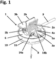
- the Fig. 1 shows the Appliziervoruze 1 in the prestressed state. It consists of a support member 6, a receiving part 10, a bottom part 11 and a cannula 8. With the support member 6, a handle part 2 is detachably connected.
- the handle part 2 can, as shown, consist of two handle blades 2a and 2b. These can be connected to each other. Alternatively, the handle wings 2a and 2b but also be separate handle parts.
- the handle part 2 can have any shape that corresponds to the ergonomic requirements, that is, for example, be round, oval or oblong.
- the outward sides of the gripping wings 2a and 2b are corrugated to increase the skid resistance.
- At least one wing 3 is also rotatably mounted about a hinge 5 on the support part 6.
- the lower end 4 of the wing 3 is arranged between two latching lugs 14a, 14b of the biasing device.
- the grip part 2 acts on the lower end 4 of the wing 3 in such a way that a rotational mobility of the wing 3 is prevented.
- Fig. 1 shows an embodiment with two wings 3a and 3b and correspondingly two hinges 5a and 5b.
- the lower part 4a and 4b of the wings 3a and 3b which point towards the grip part 2 and which engage between locking lugs 14a, 14b or - in Fig.
- a hose 9 is held by the support member 6 and is liquid-tightly connected to the cannula 8, which is arranged on the support member 6.
- Fig. 2 shows the support member 6 in the view transversely from above, after the handle part 2 has been removed.
- the wings 3a, 3b are in a rotational movement away from the top of the support member 6 to an approximately vertical position parallel to the longitudinal axis of the cannula 8.
- From the top of the support member 6 protrude locking lugs 14a, 14b, 14c and 14d in Fig. 4 better visible openings 15a, 15b, 15c and 15d.
- the mutually facing sides of the locking lugs 14a and 14b on the one hand and 14c and 14d on the other hand are chamfered.
- the lower end 4a of the wing 3a push the locking lugs 14a and 14b and the lower end 4b of the wing 3b the latches 14c and 14d apart.
- Fig. 4 shows the Appliziervorraum 1 after the biasing device has been solved.
- the (non-visible) lower ends 4a, 4b of the wings 3a, 3b have the locking lugs 14a, 14b, 14c (concealed) and 14d arranged at the free ends of the latching parts 13a, 13b, 13c (concealed) and 13d via the openings 15a, 15b , 15c (hidden) and 15d of the support member 6 are shifted so that the spring 16 can now push the support member 6 upwards.
- the cannula 8 is now pulled through the bottom opening 12 of the bottom part 11 and the receiving part 10 into the interior of the Appliziervorraum 1.
- Fig. 5 and 6 show the pretensioner.
- Fig. 5 are the locking lugs 14a, 14b, 14c and 14d to see, which protrude through the openings 15a, 15b, 15c (not visible) and 15d of the support member 6 and rest on the support member 6.
- the receiving part 10 is shown, at the bottom of the Verrast réellesmaschine 13a, 13b, 13c and 13d are attached.
- the locking lugs 14 a, 14 b, 14 c and 14 d are arranged.
- the mutually facing sides of the locking lugs 14a and 14b are chamfered.
- the Verrast ceremoniessmaschine 13a, 13b, 13c and 13d may be interconnected at its lower portion, so that a frame is formed, which prevents in the retracted state of the cannula 8 unintentional knocking of the cannula tip.
- FIG. 7a and 7b Finally, the closure device 17 for the bottom opening 12 at the bottom of the receiving part 10.
- the closure device 17 is shown in the prestressed state. It presses against the cannula 8 and thus provides, in cooperation with the bottom opening 12, a guide for the cannula 8
- Fig. 7b Fig. 3 shows the condition that exists when the cannula 8 (not shown) has been pulled through the bottom opening 12 into the interior of the applicator 1.
- the closure device 17 is now able to relax, slides over the bottom opening 12 and closes it therewith.
Landscapes
- Health & Medical Sciences (AREA)
- Heart & Thoracic Surgery (AREA)
- Life Sciences & Earth Sciences (AREA)
- Hematology (AREA)
- Engineering & Computer Science (AREA)
- Anesthesiology (AREA)
- Biomedical Technology (AREA)
- Animal Behavior & Ethology (AREA)
- General Health & Medical Sciences (AREA)
- Public Health (AREA)
- Veterinary Medicine (AREA)
- Pulmonology (AREA)
- Vascular Medicine (AREA)
- Biophysics (AREA)
- Infusion, Injection, And Reservoir Apparatuses (AREA)
- Surgical Instruments (AREA)
Abstract
Description
- Bei derartigen Appliziervorrichtungen wird die Kanüle so weit in den implantierten Port eingeführt, dass der Boden des Körpers der Appliziervorrichtung auf der Haut des Patienten aufliegt. Wenn der Injektionsvorgang beendet ist, besteht die Notwendigkeit, die Kanüle so sicher aus dem Körper des Patienten zu entfernen, dass Verletzungen oder Verunreinigungen vermieden werden. Aus diesem Grund ist es bekannt, dass die Kanüle nach dem Gebrauch aus dem Körper des Patienten direkt in den Körper der Appliziervorrichtung zurückgezogen wird.
- Eine solche Vorrichtung wird in der
EP 2 173 411 B1 beschrieben. Sie besteht aus einem Basiselement 10 und einem Zugelement 12, welches gegen das Basiselement vorgespannt ist. Die Vorspanneinrichtung besteht aus einer Druckfeder 40, an einem plattenförmigen Element (Betätigungselement) 30 angeordneten Riegelelementen 36 sowie Gegenstücken 38, die an der Unterseite des Zugelements 12 gebildet sind. Im vorgespannten Zustand sind die Riegelelemente und die Gegenstücke gegeneinander verhakt. In diesem Zustand ragt die am Zugelement befestigte Kanüle 14 durch die Öffnung 15 des Basiselements hindurch. - Das Betätigungselement ist am Boden des Basiselements in Querrichtung zur Kanülenlängsachse verschieblich angeordnet. Wird das Betätigungselement in Richtung auf die Kanüle verschoben, so wird die Verriegelung von Riegelelementen und Gegenstücken gelöst, die Druckfeder kann das Zugelement hochdrücken und damit die Kanüle in den Raum zwischen Zugelement und Basiselement zurückziehen. Wird das Betätigungselement weiter in Richtung auf die Kanüle verschoben, so verschließt das Betätigungselement die Öffnung im Boden des Basiselements und verhindert ein abermaliges Austreten der Kanülenspitze.
- Nachteilig an dieser Vorrichtung ist es, dass das Betätigungselement nicht gegen ein unbeabsichtigtes Verschieben gesichert ist. Im Gebrauch der Appliziervorrichtung kann jederzeit unbeabsichtigt eine Verschiebung des Betätigungselements erfolgen, wodurch der bestimmungsgemäße Gebrauch beeinträchtigt wird. Außerdem wird in der
EP 2 173 411 B1 als Vorteil der Erfindung beschrieben, dass die Bedienung der Appliziervorrichtung mit nur einer Hand erfolgen könne. Durch eine solche Einhandbedienung wird nicht nur die Gefahr eines unbeabsichtigten Drucks auf das Betätigungselement erhöht, da es von der Kontrolle und Fingerfertigkeit des Anwenders abhängt, ob eine bestimmungsgemäße Anwendung erfolgt. Durch die Bedienung mit nur einer Hand wird beim Verschieben des Betätigungselements durch den drückenden Finger ein Druck quer zur Längsachse der Kanüle ausgeübt, der von den anderen die Appliziervorrichtung haltenden Fingern ausgeglichen werden muss. Wenn dies nicht oder nicht genügend gelingt, ist eine Instabilität der Kanülenlage die Folge. - Es ist Aufgabe der vorliegenden Erfindung, eine Appliziervorrichtung zum perkutanen Einführen einer Kanüle in einen implantierten Port bereitzustellen, die gegen ein unbeabsichtigtes Lösen der Vorspanneinrichtung gesichert und problemlos mit einer Hand zu bedienen ist.
- Diese Aufgabe wird mit den Merkmalen des Anspruchs 1 gelöst. Vorteilhafte Ausbildungen ergeben sich aus den Unteransprüchen 2, 3 und 4.
- Erfindungsgemäß sieht die Appliziervorrichtung ein Griffteil vor, mit dem die Vorrichtung nicht nur angewendet werden kann, sondern welches auch verhindert, dass die Vorspanneinrichtung unbeabsichtigt gelöst wird. Der zum Lösen der Vorspanneinrichtung vorgesehene Flügel kann erst aktiviert werden, nachdem das Griffteil entfernt worden ist. Der Flügel wird beim Lösen der Vorspanneinrichtung um eine Drehachse verschwenkt. Das untere Ende des Flügels drückt in Richtung der Längsachse der Kanüle die Rastnasen der Verrasterungseinrichtung auseinander und verhindert damit eine ungewünschte Krafteinwirkung quer zur Längsachse der Kanüle. So bleibt die Stabilität der Position der Kanüle gewahrt.
- Im Aufnahmeteil der erfindungsgemäßen Vorrichtung ist eine Verschlussvorrichtung vorgesehen, die gegen die Kanüle vorgespannt ist. Sobald die Kanülenspitze in den Körper der Vorrichtung hineingezogen worden ist und die Bodenöffnung des Aufnahmeteils freigibt, wird diese Öffnung durch die vorgespannte Verschlussvorrichtung selbsttätig verschlossen. Eines manuellen Einwirkens vermittels eines Verschlussteils bedarf es nicht.
- Vorteilhaft ist es, wenn die Appliziervorrichtung jeweils zwei Griffteile und Flügel sowie entsprechend vier Verrasterungsteile, Rastnasen und Öffnungen im Tragteil vorsieht. Hierdurch werden die Bedienerfreundlichkeit und die Krafteinwirkung parallel zur Kanülenlängsachse beim Lösen der Vorspannvorrichtung erhöht.
- Weiterhin vorteilhaft ist es, wenn die Verschlussvorrichtung aus Blech oder aus Kunststoff gebildet ist. Diese Materialien sind preisgünstig und leicht zu bearbeiten. Dabei kann jede denkbare Art der Vorspannung ersonnen werden. Denkbar ist zum Beispiel eine am inneren Rand des Aufnahmeteils angebrachte Druckfeder, die die Verschlussvorrichtung gegen die Kanüle drückt. Denkbar ist auch, das Material der Verschlussvorrichtung vorzuspannen, beispielsweise durch Biegen nach oben, unten oder zur Seite, durch Wölbung oder durch Komprimierung in Längs- oder in Querrichtung.
- Auch ist es vorteilhaft, wenn die vorgespannte Verschlussvorrichtung so in dem Aufnahmeteil angeordnet ist, dass sie oberhalb der Bodenöffnung gegen die Kanüle drückt, wobei die Kanüle so an dem Tragteil befestigt ist, dass eine geringe Beweglichkeit gegeben ist. Wenn die Kanüle die Bodenöffnung, in der sie geführt wird, freigibt, kann die vorgespannte Verschlussvorrichtung sie in dem Maße zur Seite drücken, wie dies durch die Elastizität der Befestigung an dem Tragteil möglich ist.
- Die Erfindung soll nachfolgend anhand der
Figuren 1 bis 7 näher erläutert werden. Es zeigen - Fig. 1
- die Appliziervorrichtung im vorgespannten Zustand
- Fig. 2
- die Appliziervorrichtung nach Entfernen des Griffteils beim Lösen der Vorspannvorrichtung
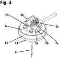
- Fig. 3
- die Appliziervorrichtung mit hochgestellten Flügeln
- Fig. 4
- die Appliziervorrichtung nach dem Lösen der Vorspannvorrichtung
- Fig. 5
- Das Tragteil in Queransicht im vorgespannten Zustand der Appliziervorrichtung
- Fig. 6
- die im Aufnahmeteil angeordneten Verrasterungsteile mit Rastnasen
- Fig. 7a
- die im Aufnahmeteil angeordnete Verschlussvorrichtung im vorgespannten Zustand
- Fig. 7b
- die im Aufnahmeteil angeordnete Verschlussvorrichtung nach dem Verschließen der Bodenöffnung
- Die
Fig. 1 zeigt die Appliziervorrichtung 1 im vorgespannten Zustand. Sie besteht aus einem Tragteil 6, einem Aufnahmeteil 10, einem Bodenteil 11 und einer Kanüle 8. Mit dem Tragteil 6 ist ein Griffteil 2 lösbar verbunden. Das Griffteil 2 kann, wie dargestellt, aus zwei Griffflügeln 2a und 2b bestehen. Diese können miteinander verbunden sein. Alternativ können die Griffflügel 2a und 2b aber auch separate Griffteile sein. Das Griffteil 2 kann jede beliebige, den ergonomischen Anforderungen entsprechende Form haben, also beispielsweise rund, oval oder länglich sein. InFig. 1 sind die nach außen gerichteten Seiten der Griffflügel 2a und 2b geriffelt, um die Rutschfestigkeit zu erhöhen. - An dem Tragteil 6 ist ferner wenigstens ein Flügel 3 um ein Scharnier 5 drehbar gelagert. Das untere Ende 4 des Flügels 3 ist zwischen zwei Rastnasen 14a, 14b der Vorspannvorrichtung angeordnet. Das Griffteil 2 wirkt so auf das untere Ende 4 des Flügels 3 ein, dass eine Drehbeweglichkeit des Flügels 3 verhindert wird.
Fig. 1 zeigt eine Ausführungsform mit zwei Flügeln 3a und 3b und entsprechend zwei Scharnieren 5a und 5b. Die zum Griffteil 2 weisenden unteren Enden 4a und 4b der Flügel 3a und 3b, die zwischen Rastnasen 14a, 14b bzw. - inFig. 2 zu sehen - 14c, 14d angeordnet sind, werden von den Griffflügeln 2a bzw. 2b des Griffteils 2 an einer Beweglichkeit gehindert, sodass die Flügel 3a und 3b nicht um die Scharniere 5a und 5b drehbar sind. Im vorgespannten Zustand der Appliziervorrichtung 1 werden die Flügel 3a und 3b mit ihren inFig. 4 sichtbaren Halteteilen 7a und 7c von ebenfalls inFig. 4 sichtbaren, am Tragteil 6 befestigten Halteteilen 7b und 7d gehalten. - Ein Schlauch 9 wird von dem Tragteil 6 gehalten und ist flüssigkeitsdicht mit der Kanüle 8 verbunden, die an dem Tragteil 6 angeordnet ist.
-
Fig. 2 zeigt das Tragteil 6 in der Ansicht quer von oben, nachdem das Griffteil 2 entfernt worden ist. Die Flügel 3a, 3b befinden sich in einer Drehbewegung weg von der Oberseite des Tragteils 6 hin zu einer in etwa vertikalen Position parallel zur Längsachse der Kanüle 8. Dabei werden die unteren Enden 4a, 4b der Flügel 3a, 3b nach unten in Richtung auf das Aufnahmeteil 10 verschwenkt. Aus der Oberseite des Tragteils 6 ragen Rastnasen 14a, 14b, 14c und 14d aus inFig. 4 besser sichtbaren Öffnungen 15a, 15b, 15c und 15d hervor. Die einander zugewandten Seiten der Rastnasen 14a und 14b einerseits sowie 14c und 14d andererseits sind abgeschrägt. In der Drehbewegung drücken das untere Ende 4a des Flügels 3a die Rastnasen 14a und 14b und das untere Ende 4b des Flügels 3b die Rastnasen 14c und 14d auseinander. - In der Darstellung in
Fig. 3 haben die Flügel 3a, 3b ihre in etwa vertikale Position erreicht. Zu erkennen ist jetzt das Halteteil 7a am Flügel 3a, welches im umgeklappten Zustand des Flügels 3a vom Halteteil 7b des Tragteils gehalten wird, z.B. durch Verrasten. Entsprechendes gilt für den Flügel 3b mit seinem nicht dargestellten Halteteil 7c in Bezug auf das am Tragteil 6 angeordnete Halteteil 7d. -
Fig. 4 zeigt die Appliziervorrichtung 1, nachdem die Vorspannvorrichtung gelöst worden ist. Die (nicht sichtbaren) unteren Enden 4a, 4b der Flügel 3a, 3b haben die am freien Ende der Verrasterungsteile 13a, 13b, 13c (verdeckt) und 13d angeordneten Rastnasen 14a, 14b, 14c (verdeckt) und 14d über die Öffnungen 15a, 15b, 15c (verdeckt) und 15d des Tragteils 6 verschoben, sodass die Feder 16 das Tragteil 6 jetzt nach oben drücken kann. Die Kanüle 8 wird nunmehr durch die Bodenöffnung 12 des Bodenteils 11 und des Aufnahmeteils 10 in das Innere der Appliziervorrichtung 1 gezogen. - Die
Fig. 5 und6 zeigen die Vorspannvorrichtung. InFig. 5 sind die Rastnasen 14a, 14b, 14c und 14d zu sehen, die durch die Öffnungen 15a, 15b, 15c (nicht sichtbar) und 15d des Tragteils 6 ragen und auf dem Tragteil 6 aufliegen. InFig. 6 ist das Aufnahmeteil 10 dargestellt, an dessen Boden die Verrasterungsteile 13a, 13b, 13c und 13d befestigt sind. Am freien Ende der Verrasterungsteile 13a, 13b, 13c und 13d sind die Rastnasen 14a, 14b, 14c und 14d angeordnet. Die einander zugewandten Seiten der Rastnasen 14a und 14b sind abgeschrägt. Gleiches gilt für die Rastnasen 14c und 14d. Die Verrasterungsteile 13a, 13b, 13c und 13d können an ihrem unteren Bereich miteinander verbunden sein, sodass ein Rahmen gebildet wird, der im eingezogenen Zustand der Kanüle 8 ein ungewolltes Ausschlagen der Kanülenspitze verhindert. - Die
Fig. 7a und 7b schließlich zeigen die Verschlussvorrichtung 17 für die Bodenöffnung 12 am Boden des Aufnahmeteils 10. InFig. 7a ist die Verschlussvorrichtung 17 im vorgespannten Zustand dargestellt. Sie drückt gegen die Kanüle 8 und stellt damit im Zusammenwirken mit der Bodenöffnung 12 eine Führung für die Kanüle 8 dar. InFig. 7b wird der Zustand gezeigt, der besteht, wenn die Kanüle 8 (nicht dargestellt) durch die Bodenöffnung 12 in das Innere der Appliziervorrichtung 1 gezogen worden ist. Die Verschlussvorrichtung 17 kann sich jetzt entspannen, gleitet über die Bodenöffnung 12 und verschließt sie damit. -
- 1
- Appliziervorrichtung
- 2a
- Griffflügel
- 2b
- Griffflügel
- 3a
- Flügel
- 3b
- Flügel
- 4a
- unteres Ende des Flügels 3a
- 4b
- unteres Ende des Flügels 3b
- 5a
- Scharnier
- 5b
- Scharnier
- 6
- Tragteil
- 7a
- Halteteil
- 7b
- Halteteil
- 7c
- Halteteil
- 7d
- Halteteil
- 8
- Kanüle
- 9
- Schlauch
- 10
- Aufnahmeteil
- 11
- Auflageteil
- 12
- Bodenöffnung
- 13a
- Verrasterungsteil
- 13b
- Verrasterungsteil
- 13c
- Verrasterungsteil
- 13d
- Verrasterungsteil
- 14a
- Rastnase
- 14b
- Rastnase
- 14c
- Rastnase
- 14d
- Rastnase
- 15a
- Öffnung
- 15b
- Öffnung
- 15c
- Öffnung
- 15d
- Öffnung
- 16
- Feder
- 17
- Verschlussvorrichtung
Claims (4)
- Appliziervorrichtung (1) für eine Kanüle (8)- mit wenigstens einem lösbar verbundenen Griffteil (2), das zugleich als Sicherungseinrichtung gegen ein Auslösen der Vorspanneinrichtung dient- mit einem Tragteil (6)- mit einem Aufnahmeteil (10)- mit einem Auflageteil (11)- mit einer Kanüle (8)- die Kanüle (8) ragt im vorgespannten Zustand der Appliziervorrichtung (1) durch die Bodenöffnungen (12) des Aufnahmeteils (10) und des Auflageteils (11) hindurch- die Kanüle (8) ist an dem Tragteil (6) befestigt- an dem Tragteil (6) ist wenigstens ein Flügel (3) drehbeweglich angeordnet- in der Nichtgebrauchsstellung wird der wenigstens eine Flügel (3) von seinem Halteteil (7a) an einem Halteteil (7b) des Tragteils gehalten und durch das Griffteil (2) gegen ein Anheben gesichert- das Tragteil (6) ist in einem Aufnahmeteil (10) angeordnet- das Aufnahmeteil (10) weist wenigstens zwei Verrasterungsteile (13a, 13b) auf, die in etwa senkrecht vom Boden des Aufnahmeteils (10) aufragen- die oberen Enden der Verrasterungsteile (13a,13b) weisen einander zugewandte Rastnasen (14a,14b) auf- die einander zugewandten Seiten der Rastnasen (14a, 14b) sind abgeschrägt- das Tragteil (6) ist durch eine Feder (16) gegen das Aufnahmeteil (10) vorgespannt- in dem vorgespannten Zustand ragen die wenigstens zwei Rastnasen (14a, 14b) durch wenigstens zwei Öffnungen (15a, 15b) des Tragteils (6) hindurch und liegen auf der Oberseite des Tragteils (6) auf- in dem vorgespannten Zustand ist das untere Ende (4) des wenigstens einen Flügels (3) zwischen den abgeschrägten Seiten der wenigstens zwei Rastnasen (14a, 14b) angeordnet- nach Entfernen des wenigstens einen Griffteils (2) wird durch Hochziehen des wenigstens einen Flügels (3) das Halteteil (7a) des wenigstens einen Flügels (3) von dem Halteteil (7b) des Tragteils (6) gelöst- durch das Verdrehen des wenigstens einen Flügels (3) in eine in etwa vertikale Position drückt das untere Ende (4) des wenigstens einen Flügels (3) die Rastnasen (14a, 14b) auseinander und löst damit die Vorspannvorrichtung- durch das Lösen der Vorspannvorrichtung wird das Tragteil (6) nach oben gedrückt und zieht die Kanüle (8) vollständig in den Raum zwischen Tragteil (6) und Aufnahmeteil (10) hinein- in dem Aufnahmeteil (10) ist eine vorgespannte Verschlusseinrichtung (17) angeordnet, die, sobald die Kanüle (8) durch die Bodenöffnungen (12) hindurchgezogen worden ist, selbsttätig die Bodenöffnung (12) des Aufnahmeteils (10) verschließt.
- Appliziervorrichtung (1) nach Anspruch 1,- mit zwei Griffteilen (2a,2b)- mit zwei Flügeln (3a,3b)- mit vier Verrasterungsteilen (13a,13b,13c,13d)- mit vier Rastnasen (14a,14b,14c,14d)- mit vier Öffnungen (15a,15b,15c,15d) im Tragteil (6).
- Appliziervorrichtung (1) nach einem der vorangegangenen Ansprüche, bei der die Verschlussvorrichtung (17) als vorgespanntes Blech oder als vorgespanntes Kunststoffteil ausgebildet ist.
- Appliziervorrichtung (1) nach einem der vorangehenden Ansprüche, bei der die vorgespannte Verschlussvorrichtung (17) gegen die Kanüle (8) drückt und das untere Ende der Kanüle (8), sobald diese die Bodenöffnung (12) freigegeben hat, so zur Seite drückt, dass ein neuerliches Hindurchtreten der Kanülenspitze durch die Bodenöffnung (12) verhindert wird.
Applications Claiming Priority (1)
| Application Number | Priority Date | Filing Date | Title |
|---|---|---|---|
| DE102017003808.2A DE102017003808A1 (de) | 2017-04-20 | 2017-04-20 | Appliziervorrichtung zum perkutanen Einführen einer Kanüle in einen implantierten Port |
Publications (2)
| Publication Number | Publication Date |
|---|---|
| EP3391920A1 true EP3391920A1 (de) | 2018-10-24 |
| EP3391920B1 EP3391920B1 (de) | 2020-11-18 |
Family
ID=62017143
Family Applications (1)
| Application Number | Title | Priority Date | Filing Date |
|---|---|---|---|
| EP18000362.6A Active EP3391920B1 (de) | 2017-04-20 | 2018-04-16 | Appliziervorrichtung zum perkutanen einführen einer kanüle in einen implantierten port |
Country Status (2)
| Country | Link |
|---|---|
| EP (1) | EP3391920B1 (de) |
| DE (1) | DE102017003808A1 (de) |
Citations (4)
| Publication number | Priority date | Publication date | Assignee | Title |
|---|---|---|---|---|
| US6238375B1 (en) * | 1996-01-02 | 2001-05-29 | Richard R. Powell | Retractable cover extraction for intravenous and other therapy needles |
| DE10333118A1 (de) * | 2002-11-29 | 2004-06-17 | Disetronic Licensing Ag | Einstechvorrichtung zum Einstechen einer Injektionsnadel |
| DE102007011303A1 (de) * | 2007-03-06 | 2008-09-11 | Acti-Med Ag | Sicherheitsnadelvorrichtung |
| EP2173411B1 (de) | 2007-08-09 | 2015-11-11 | Mantsch, Christian | Vorrichtung zum applizieren einer kanüle |
Family Cites Families (4)
| Publication number | Priority date | Publication date | Assignee | Title |
|---|---|---|---|---|
| JP4319601B2 (ja) * | 2004-08-26 | 2009-08-26 | 川澄化学工業株式会社 | 翼付湾曲針 |
| US20140066894A1 (en) * | 2010-09-10 | 2014-03-06 | C. R. Bard, Inc. | Self-Sealing Pad for a Needle-Based Infusion Set |
| US9125985B2 (en) * | 2013-04-01 | 2015-09-08 | iMed Technology, Inc. | Needle with protective cover member |
| US10478566B2 (en) * | 2014-08-29 | 2019-11-19 | Medical Components, Inc. | Huber safety needle |
-
2017
- 2017-04-20 DE DE102017003808.2A patent/DE102017003808A1/de not_active Withdrawn
-
2018
- 2018-04-16 EP EP18000362.6A patent/EP3391920B1/de active Active
Patent Citations (4)
| Publication number | Priority date | Publication date | Assignee | Title |
|---|---|---|---|---|
| US6238375B1 (en) * | 1996-01-02 | 2001-05-29 | Richard R. Powell | Retractable cover extraction for intravenous and other therapy needles |
| DE10333118A1 (de) * | 2002-11-29 | 2004-06-17 | Disetronic Licensing Ag | Einstechvorrichtung zum Einstechen einer Injektionsnadel |
| DE102007011303A1 (de) * | 2007-03-06 | 2008-09-11 | Acti-Med Ag | Sicherheitsnadelvorrichtung |
| EP2173411B1 (de) | 2007-08-09 | 2015-11-11 | Mantsch, Christian | Vorrichtung zum applizieren einer kanüle |
Also Published As
| Publication number | Publication date |
|---|---|
| DE102017003808A1 (de) | 2018-10-25 |
| EP3391920B1 (de) | 2020-11-18 |
Similar Documents
| Publication | Publication Date | Title |
|---|---|---|
| EP2804504B1 (de) | Medienspender | |
| DE2419818A1 (de) | Pinzette | |
| EP1915185A1 (de) | Spritze | |
| DE202009009602U1 (de) | Kathetervorrichtung mit Nadelschutz | |
| DE9202027U1 (de) | Schieber für Schirme o.dgl. | |
| EP1886939A2 (de) | Abgabekopf für einen Druckbehälter | |
| DE102010005283A1 (de) | Sicherheitsvorrichtung für automatisch auf- und zusammenklappbaren Regenschirm | |
| EP2015697B1 (de) | Sammel- und entsorgungsbehälter, insbesondere für kanülen | |
| EP4289574B1 (de) | Messer | |
| EP2853665B1 (de) | Türgriff | |
| DE102004031004B4 (de) | Feststelleinrichtung für einen aufklappbaren Ladeboden in einem Fahrzeug | |
| DE102010027153A1 (de) | Karabinerhaken | |
| DE202008004468U1 (de) | Betätigungsmechanismus für einen Regenschirm | |
| EP3391920A1 (de) | Appliziervorrichtung zum perkutanen einführen einer kanüle in einen implantierten port | |
| EP3636104B1 (de) | Kopplungsvorrichtung für auszugsführung | |
| EP2682932B1 (de) | Klappaufsteller für die Präsentation einer Anzeigefläche | |
| DE60021784T2 (de) | Verbesserter Korkenzieher | |
| DE102008052787A1 (de) | Kanüle mit Schutzvorrichtung | |
| EP3459905A1 (de) | Kellnermesser | |
| DE102020108954A1 (de) | Arretierungsmechanismus für eine Front eines in einer Fahrzeugtür vorgesehenen Staufachs | |
| CH629271A5 (en) | Securing means for WC deodorisers | |
| AT526360B1 (de) | Anordnung mit zumindest einer Falttür oder Falt-Schiebe-Tür | |
| EP2539159B1 (de) | Ordnermechanik | |
| DE102013022154A1 (de) | Abdeckvorrichtung | |
| DE3120264A1 (de) | Kapselheber |
Legal Events
| Date | Code | Title | Description |
|---|---|---|---|
| PUAI | Public reference made under article 153(3) epc to a published international application that has entered the european phase |
Free format text: ORIGINAL CODE: 0009012 |
|
| STAA | Information on the status of an ep patent application or granted ep patent |
Free format text: STATUS: REQUEST FOR EXAMINATION WAS MADE |
|
| 17P | Request for examination filed |
Effective date: 20180504 |
|
| AK | Designated contracting states |
Kind code of ref document: A1 Designated state(s): AL AT BE BG CH CY CZ DE DK EE ES FI FR GB GR HR HU IE IS IT LI LT LU LV MC MK MT NL NO PL PT RO RS SE SI SK SM TR |
|
| AX | Request for extension of the european patent |
Extension state: BA ME |
|
| STAA | Information on the status of an ep patent application or granted ep patent |
Free format text: STATUS: EXAMINATION IS IN PROGRESS |
|
| 17Q | First examination report despatched |
Effective date: 20181024 |
|
| GRAP | Despatch of communication of intention to grant a patent |
Free format text: ORIGINAL CODE: EPIDOSNIGR1 |
|
| STAA | Information on the status of an ep patent application or granted ep patent |
Free format text: STATUS: GRANT OF PATENT IS INTENDED |
|
| RIC1 | Information provided on ipc code assigned before grant |
Ipc: A61M 5/32 20060101ALI20200506BHEP Ipc: A61M 25/06 20060101ALI20200506BHEP Ipc: A61M 39/02 20060101ALI20200506BHEP Ipc: A61M 5/142 20060101ALI20200506BHEP Ipc: A61M 25/02 20060101ALI20200506BHEP Ipc: A61M 39/10 20060101ALI20200506BHEP Ipc: A61M 5/158 20060101AFI20200506BHEP Ipc: A61M 25/00 20060101ALI20200506BHEP |
|
| INTG | Intention to grant announced |
Effective date: 20200608 |
|
| GRAS | Grant fee paid |
Free format text: ORIGINAL CODE: EPIDOSNIGR3 |
|
| GRAA | (expected) grant |
Free format text: ORIGINAL CODE: 0009210 |
|
| STAA | Information on the status of an ep patent application or granted ep patent |
Free format text: STATUS: THE PATENT HAS BEEN GRANTED |
|
| AK | Designated contracting states |
Kind code of ref document: B1 Designated state(s): AL AT BE BG CH CY CZ DE DK EE ES FI FR GB GR HR HU IE IS IT LI LT LU LV MC MK MT NL NO PL PT RO RS SE SI SK SM TR |
|
| REG | Reference to a national code |
Ref country code: GB Ref legal event code: FG4D Free format text: NOT ENGLISH |
|
| REG | Reference to a national code |
Ref country code: CH Ref legal event code: EP |
|
| REG | Reference to a national code |
Ref country code: IE Ref legal event code: FG4D Free format text: LANGUAGE OF EP DOCUMENT: GERMAN |
|
| REG | Reference to a national code |
Ref country code: DE Ref legal event code: R096 Ref document number: 502018003003 Country of ref document: DE |
|
| REG | Reference to a national code |
Ref country code: AT Ref legal event code: REF Ref document number: 1335060 Country of ref document: AT Kind code of ref document: T Effective date: 20201215 |
|
| REG | Reference to a national code |
Ref country code: NL Ref legal event code: MP Effective date: 20201118 |
|
| PG25 | Lapsed in a contracting state [announced via postgrant information from national office to epo] |
Ref country code: PT Free format text: LAPSE BECAUSE OF FAILURE TO SUBMIT A TRANSLATION OF THE DESCRIPTION OR TO PAY THE FEE WITHIN THE PRESCRIBED TIME-LIMIT Effective date: 20210318 Ref country code: RS Free format text: LAPSE BECAUSE OF FAILURE TO SUBMIT A TRANSLATION OF THE DESCRIPTION OR TO PAY THE FEE WITHIN THE PRESCRIBED TIME-LIMIT Effective date: 20201118 Ref country code: FI Free format text: LAPSE BECAUSE OF FAILURE TO SUBMIT A TRANSLATION OF THE DESCRIPTION OR TO PAY THE FEE WITHIN THE PRESCRIBED TIME-LIMIT Effective date: 20201118 Ref country code: NO Free format text: LAPSE BECAUSE OF FAILURE TO SUBMIT A TRANSLATION OF THE DESCRIPTION OR TO PAY THE FEE WITHIN THE PRESCRIBED TIME-LIMIT Effective date: 20210218 Ref country code: GR Free format text: LAPSE BECAUSE OF FAILURE TO SUBMIT A TRANSLATION OF THE DESCRIPTION OR TO PAY THE FEE WITHIN THE PRESCRIBED TIME-LIMIT Effective date: 20210219 |
|
| PG25 | Lapsed in a contracting state [announced via postgrant information from national office to epo] |
Ref country code: BG Free format text: LAPSE BECAUSE OF FAILURE TO SUBMIT A TRANSLATION OF THE DESCRIPTION OR TO PAY THE FEE WITHIN THE PRESCRIBED TIME-LIMIT Effective date: 20210218 Ref country code: LV Free format text: LAPSE BECAUSE OF FAILURE TO SUBMIT A TRANSLATION OF THE DESCRIPTION OR TO PAY THE FEE WITHIN THE PRESCRIBED TIME-LIMIT Effective date: 20201118 Ref country code: PL Free format text: LAPSE BECAUSE OF FAILURE TO SUBMIT A TRANSLATION OF THE DESCRIPTION OR TO PAY THE FEE WITHIN THE PRESCRIBED TIME-LIMIT Effective date: 20201118 Ref country code: IS Free format text: LAPSE BECAUSE OF FAILURE TO SUBMIT A TRANSLATION OF THE DESCRIPTION OR TO PAY THE FEE WITHIN THE PRESCRIBED TIME-LIMIT Effective date: 20210318 Ref country code: SE Free format text: LAPSE BECAUSE OF FAILURE TO SUBMIT A TRANSLATION OF THE DESCRIPTION OR TO PAY THE FEE WITHIN THE PRESCRIBED TIME-LIMIT Effective date: 20201118 |
|
| REG | Reference to a national code |
Ref country code: LT Ref legal event code: MG9D |
|
| PG25 | Lapsed in a contracting state [announced via postgrant information from national office to epo] |
Ref country code: HR Free format text: LAPSE BECAUSE OF FAILURE TO SUBMIT A TRANSLATION OF THE DESCRIPTION OR TO PAY THE FEE WITHIN THE PRESCRIBED TIME-LIMIT Effective date: 20201118 |
|
| PG25 | Lapsed in a contracting state [announced via postgrant information from national office to epo] |
Ref country code: RO Free format text: LAPSE BECAUSE OF FAILURE TO SUBMIT A TRANSLATION OF THE DESCRIPTION OR TO PAY THE FEE WITHIN THE PRESCRIBED TIME-LIMIT Effective date: 20201118 Ref country code: SK Free format text: LAPSE BECAUSE OF FAILURE TO SUBMIT A TRANSLATION OF THE DESCRIPTION OR TO PAY THE FEE WITHIN THE PRESCRIBED TIME-LIMIT Effective date: 20201118 Ref country code: LT Free format text: LAPSE BECAUSE OF FAILURE TO SUBMIT A TRANSLATION OF THE DESCRIPTION OR TO PAY THE FEE WITHIN THE PRESCRIBED TIME-LIMIT Effective date: 20201118 Ref country code: CZ Free format text: LAPSE BECAUSE OF FAILURE TO SUBMIT A TRANSLATION OF THE DESCRIPTION OR TO PAY THE FEE WITHIN THE PRESCRIBED TIME-LIMIT Effective date: 20201118 Ref country code: EE Free format text: LAPSE BECAUSE OF FAILURE TO SUBMIT A TRANSLATION OF THE DESCRIPTION OR TO PAY THE FEE WITHIN THE PRESCRIBED TIME-LIMIT Effective date: 20201118 Ref country code: SM Free format text: LAPSE BECAUSE OF FAILURE TO SUBMIT A TRANSLATION OF THE DESCRIPTION OR TO PAY THE FEE WITHIN THE PRESCRIBED TIME-LIMIT Effective date: 20201118 |
|
| REG | Reference to a national code |
Ref country code: DE Ref legal event code: R097 Ref document number: 502018003003 Country of ref document: DE |
|
| PG25 | Lapsed in a contracting state [announced via postgrant information from national office to epo] |
Ref country code: DK Free format text: LAPSE BECAUSE OF FAILURE TO SUBMIT A TRANSLATION OF THE DESCRIPTION OR TO PAY THE FEE WITHIN THE PRESCRIBED TIME-LIMIT Effective date: 20201118 |
|
| PLBE | No opposition filed within time limit |
Free format text: ORIGINAL CODE: 0009261 |
|
| STAA | Information on the status of an ep patent application or granted ep patent |
Free format text: STATUS: NO OPPOSITION FILED WITHIN TIME LIMIT |
|
| 26N | No opposition filed |
Effective date: 20210819 |
|
| PG25 | Lapsed in a contracting state [announced via postgrant information from national office to epo] |
Ref country code: IT Free format text: LAPSE BECAUSE OF FAILURE TO SUBMIT A TRANSLATION OF THE DESCRIPTION OR TO PAY THE FEE WITHIN THE PRESCRIBED TIME-LIMIT Effective date: 20201118 Ref country code: AL Free format text: LAPSE BECAUSE OF FAILURE TO SUBMIT A TRANSLATION OF THE DESCRIPTION OR TO PAY THE FEE WITHIN THE PRESCRIBED TIME-LIMIT Effective date: 20201118 Ref country code: NL Free format text: LAPSE BECAUSE OF FAILURE TO SUBMIT A TRANSLATION OF THE DESCRIPTION OR TO PAY THE FEE WITHIN THE PRESCRIBED TIME-LIMIT Effective date: 20201118 |
|
| PG25 | Lapsed in a contracting state [announced via postgrant information from national office to epo] |
Ref country code: SI Free format text: LAPSE BECAUSE OF FAILURE TO SUBMIT A TRANSLATION OF THE DESCRIPTION OR TO PAY THE FEE WITHIN THE PRESCRIBED TIME-LIMIT Effective date: 20201118 Ref country code: MC Free format text: LAPSE BECAUSE OF FAILURE TO SUBMIT A TRANSLATION OF THE DESCRIPTION OR TO PAY THE FEE WITHIN THE PRESCRIBED TIME-LIMIT Effective date: 20201118 |
|
| PG25 | Lapsed in a contracting state [announced via postgrant information from national office to epo] |
Ref country code: LU Free format text: LAPSE BECAUSE OF NON-PAYMENT OF DUE FEES Effective date: 20210416 |
|
| REG | Reference to a national code |
Ref country code: BE Ref legal event code: MM Effective date: 20210430 |
|
| PG25 | Lapsed in a contracting state [announced via postgrant information from national office to epo] |
Ref country code: ES Free format text: LAPSE BECAUSE OF FAILURE TO SUBMIT A TRANSLATION OF THE DESCRIPTION OR TO PAY THE FEE WITHIN THE PRESCRIBED TIME-LIMIT Effective date: 20201118 |
|
| REG | Reference to a national code |
Ref country code: DE Ref legal event code: R081 Ref document number: 502018003003 Country of ref document: DE Owner name: ACTI-MED GMBH, DE Free format text: FORMER OWNER: ACTI-MED AG, 36399 FREIENSTEINAU, DE Ref country code: DE Ref legal event code: R081 Ref document number: 502018003003 Country of ref document: DE Owner name: JECTURE GERMANY GMBH, DE Free format text: FORMER OWNER: ACTI-MED AG, 36399 FREIENSTEINAU, DE |
|
| PG25 | Lapsed in a contracting state [announced via postgrant information from national office to epo] |
Ref country code: IE Free format text: LAPSE BECAUSE OF NON-PAYMENT OF DUE FEES Effective date: 20210416 |
|
| PG25 | Lapsed in a contracting state [announced via postgrant information from national office to epo] |
Ref country code: IS Free format text: LAPSE BECAUSE OF FAILURE TO SUBMIT A TRANSLATION OF THE DESCRIPTION OR TO PAY THE FEE WITHIN THE PRESCRIBED TIME-LIMIT Effective date: 20210318 |
|
| PG25 | Lapsed in a contracting state [announced via postgrant information from national office to epo] |
Ref country code: BE Free format text: LAPSE BECAUSE OF NON-PAYMENT OF DUE FEES Effective date: 20210430 |
|
| REG | Reference to a national code |
Ref country code: CH Ref legal event code: PL |
|
| GBPC | Gb: european patent ceased through non-payment of renewal fee |
Effective date: 20220416 |
|
| PG25 | Lapsed in a contracting state [announced via postgrant information from national office to epo] |
Ref country code: LI Free format text: LAPSE BECAUSE OF NON-PAYMENT OF DUE FEES Effective date: 20220430 Ref country code: GB Free format text: LAPSE BECAUSE OF NON-PAYMENT OF DUE FEES Effective date: 20220416 Ref country code: CH Free format text: LAPSE BECAUSE OF NON-PAYMENT OF DUE FEES Effective date: 20220430 |
|
| PG25 | Lapsed in a contracting state [announced via postgrant information from national office to epo] |
Ref country code: LI Free format text: LAPSE BECAUSE OF NON-PAYMENT OF DUE FEES Effective date: 20220430 Ref country code: CH Free format text: LAPSE BECAUSE OF NON-PAYMENT OF DUE FEES Effective date: 20220430 |
|
| PGRI | Patent reinstated in contracting state [announced from national office to epo] |
Ref country code: LI Effective date: 20230105 Ref country code: CH Effective date: 20230105 |
|
| PG25 | Lapsed in a contracting state [announced via postgrant information from national office to epo] |
Ref country code: CY Free format text: LAPSE BECAUSE OF FAILURE TO SUBMIT A TRANSLATION OF THE DESCRIPTION OR TO PAY THE FEE WITHIN THE PRESCRIBED TIME-LIMIT Effective date: 20201118 |
|
| PG25 | Lapsed in a contracting state [announced via postgrant information from national office to epo] |
Ref country code: HU Free format text: LAPSE BECAUSE OF FAILURE TO SUBMIT A TRANSLATION OF THE DESCRIPTION OR TO PAY THE FEE WITHIN THE PRESCRIBED TIME-LIMIT; INVALID AB INITIO Effective date: 20180416 |
|
| PG25 | Lapsed in a contracting state [announced via postgrant information from national office to epo] |
Ref country code: MK Free format text: LAPSE BECAUSE OF FAILURE TO SUBMIT A TRANSLATION OF THE DESCRIPTION OR TO PAY THE FEE WITHIN THE PRESCRIBED TIME-LIMIT Effective date: 20201118 |
|
| REG | Reference to a national code |
Ref country code: DE Ref legal event code: R082 Ref document number: 502018003003 Country of ref document: DE Representative=s name: PATENTANWAELTE HABERMANN, HRUSCHKA & SCHNABEL, DE |
|
| PG25 | Lapsed in a contracting state [announced via postgrant information from national office to epo] |
Ref country code: MT Free format text: LAPSE BECAUSE OF FAILURE TO SUBMIT A TRANSLATION OF THE DESCRIPTION OR TO PAY THE FEE WITHIN THE PRESCRIBED TIME-LIMIT Effective date: 20201118 |
|
| REG | Reference to a national code |
Ref country code: AT Ref legal event code: HC Ref document number: 1335060 Country of ref document: AT Kind code of ref document: T Owner name: ACTI-MED GMBH, DE Effective date: 20241021 |
|
| PGFP | Annual fee paid to national office [announced via postgrant information from national office to epo] |
Ref country code: FR Payment date: 20250205 Year of fee payment: 8 |
|
| PGFP | Annual fee paid to national office [announced via postgrant information from national office to epo] |
Ref country code: DE Payment date: 20250205 Year of fee payment: 8 |
|
| PGFP | Annual fee paid to national office [announced via postgrant information from national office to epo] |
Ref country code: CH Payment date: 20250501 Year of fee payment: 8 |
|
| PGFP | Annual fee paid to national office [announced via postgrant information from national office to epo] |
Ref country code: AT Payment date: 20250207 Year of fee payment: 8 |
|
| PG25 | Lapsed in a contracting state [announced via postgrant information from national office to epo] |
Ref country code: TR Free format text: LAPSE BECAUSE OF FAILURE TO SUBMIT A TRANSLATION OF THE DESCRIPTION OR TO PAY THE FEE WITHIN THE PRESCRIBED TIME-LIMIT Effective date: 20201118 |
|
| REG | Reference to a national code |
Ref country code: CH Ref legal event code: R18 Free format text: ST27 STATUS EVENT CODE: U-0-0-R10-R18 (AS PROVIDED BY THE NATIONAL OFFICE) Effective date: 20260109 |
|
| REG | Reference to a national code |
Ref country code: DE Ref legal event code: R081 Ref document number: 502018003003 Country of ref document: DE Owner name: JECTURE GERMANY GMBH, DE Free format text: FORMER OWNER: ACTI-MED GMBH, 36399 FREIENSTEINAU, DE |
|
| REG | Reference to a national code |
Ref country code: AT Ref legal event code: HC Ref document number: 1335060 Country of ref document: AT Kind code of ref document: T Owner name: JECTURE GERMANY GMBH, DE Effective date: 20260223 |