EP3391822B1 - Verfahren und systeme für einen kompakten integrierten monitorarm für ein bildgebungssystem - Google Patents
Verfahren und systeme für einen kompakten integrierten monitorarm für ein bildgebungssystem Download PDFInfo
- Publication number
- EP3391822B1 EP3391822B1 EP18167506.7A EP18167506A EP3391822B1 EP 3391822 B1 EP3391822 B1 EP 3391822B1 EP 18167506 A EP18167506 A EP 18167506A EP 3391822 B1 EP3391822 B1 EP 3391822B1
- Authority
- EP
- European Patent Office
- Prior art keywords
- arm
- display monitor
- joint
- imaging system
- coupled
- Prior art date
- Legal status (The legal status is an assumption and is not a legal conclusion. Google has not performed a legal analysis and makes no representation as to the accuracy of the status listed.)
- Active
Links
Images






Classifications
-
- A—HUMAN NECESSITIES
- A61—MEDICAL OR VETERINARY SCIENCE; HYGIENE
- A61B—DIAGNOSIS; SURGERY; IDENTIFICATION
- A61B6/00—Apparatus or devices for radiation diagnosis; Apparatus or devices for radiation diagnosis combined with radiation therapy equipment
- A61B6/44—Constructional features of apparatus for radiation diagnosis
- A61B6/4429—Constructional features of apparatus for radiation diagnosis related to the mounting of source units and detector units
- A61B6/4435—Constructional features of apparatus for radiation diagnosis related to the mounting of source units and detector units the source unit and the detector unit being coupled by a rigid structure
- A61B6/4441—Constructional features of apparatus for radiation diagnosis related to the mounting of source units and detector units the source unit and the detector unit being coupled by a rigid structure the rigid structure being a C-arm or U-arm
-
- A—HUMAN NECESSITIES
- A61—MEDICAL OR VETERINARY SCIENCE; HYGIENE
- A61B—DIAGNOSIS; SURGERY; IDENTIFICATION
- A61B6/00—Apparatus or devices for radiation diagnosis; Apparatus or devices for radiation diagnosis combined with radiation therapy equipment
- A61B6/46—Arrangements for interfacing with the operator or the patient
-
- A—HUMAN NECESSITIES
- A61—MEDICAL OR VETERINARY SCIENCE; HYGIENE
- A61B—DIAGNOSIS; SURGERY; IDENTIFICATION
- A61B6/00—Apparatus or devices for radiation diagnosis; Apparatus or devices for radiation diagnosis combined with radiation therapy equipment
- A61B6/44—Constructional features of apparatus for radiation diagnosis
-
- A—HUMAN NECESSITIES
- A61—MEDICAL OR VETERINARY SCIENCE; HYGIENE
- A61B—DIAGNOSIS; SURGERY; IDENTIFICATION
- A61B6/00—Apparatus or devices for radiation diagnosis; Apparatus or devices for radiation diagnosis combined with radiation therapy equipment
- A61B6/44—Constructional features of apparatus for radiation diagnosis
- A61B6/4405—Constructional features of apparatus for radiation diagnosis the apparatus being movable or portable, e.g. handheld or mounted on a trolley
-
- A—HUMAN NECESSITIES
- A61—MEDICAL OR VETERINARY SCIENCE; HYGIENE
- A61B—DIAGNOSIS; SURGERY; IDENTIFICATION
- A61B6/00—Apparatus or devices for radiation diagnosis; Apparatus or devices for radiation diagnosis combined with radiation therapy equipment
- A61B6/44—Constructional features of apparatus for radiation diagnosis
- A61B6/4429—Constructional features of apparatus for radiation diagnosis related to the mounting of source units and detector units
- A61B6/4452—Constructional features of apparatus for radiation diagnosis related to the mounting of source units and detector units the source unit and the detector unit being able to move relative to each other
-
- A—HUMAN NECESSITIES
- A61—MEDICAL OR VETERINARY SCIENCE; HYGIENE
- A61B—DIAGNOSIS; SURGERY; IDENTIFICATION
- A61B6/00—Apparatus or devices for radiation diagnosis; Apparatus or devices for radiation diagnosis combined with radiation therapy equipment
- A61B6/46—Arrangements for interfacing with the operator or the patient
- A61B6/461—Displaying means of special interest
- A61B6/462—Displaying means of special interest characterised by constructional features of the display
-
- A—HUMAN NECESSITIES
- A61—MEDICAL OR VETERINARY SCIENCE; HYGIENE
- A61B—DIAGNOSIS; SURGERY; IDENTIFICATION
- A61B6/00—Apparatus or devices for radiation diagnosis; Apparatus or devices for radiation diagnosis combined with radiation therapy equipment
- A61B6/10—Safety means specially adapted therefor
- A61B6/102—Protection against mechanical damage, e.g. anti-collision devices
- A61B6/105—Braking or locking devices
Definitions
- US 2012/016222 A1 discloses a medical imaging system.
- the medical imaging system comprises a movable acquisition device, a processing unit and a display, wherein the display is fixed to the movable acquisition device.
- the following description relates to various embodiments of a compact integrated arm for a display monitor coupled to an imaging system.
- the integrated arm may include a fixed arm and an articulating arm coupled to one another via an elbow joint, as shown in FIGS. 1-3 .
- One end of the fixed arm may be coupled to the cross member via a shoulder joint, and the other end of the fixed arm may be coupled to the elbow joint connected to the articulating arm.
- the fixed arm may include two offset joints, including the shoulder joint and elbow joint, arranged on opposite ends of the fixed arm.
- the shoulder joint may couple a straight portion of the fixed arm to the C-arm and the elbow joint may couple a curved portion of the fixed arm to the articulating arm, as shown in FIGS. 1-3 .
- the elbow joint may be configured to rotate through an angle of 0 to 180 degrees, for example. In this case, movement of the elbow joint allows the articulating arm coupled to the display monitor (via a wrist joint) to be adjusted through a wide range of positions.
- the wrist joint may be adapted for rotational movement, thereby allowing the display monitor to be oriented to a suitable position within the horizontal plane, as disclosed in FIGS. 4A-10B .
- the display monitor When the imaging system is in use, the display monitor may be adjusted from the parked position to an unlocked position behind the C-arm by orienting the articulating arm upward as shown in FIG.5A .
- the fixed arm and elbow joint may be kept in prior positions disclosed in FIGS. 4A-B , while reorienting the articulating arm and display monitor in an upward direction as shown in FIG. 5A .
- the display monitor may be positioned behind the C-arm and facing a first side of the C-arm, as shown in FIG. 5B .
- the display monitor may be moved from the retracted position behind the C-arm to a position where the display monitor is partially positioned on the first and second side of the C-arm, by rotating the fixed arm via the shoulder joint without readjusting the elbow joint and articulating arm.
- the fixed arm may be adjusted outward and away from the C-arm via the shoulder joint which is rotated about the shoulder axis without readjusting the articulating arm coupled to the elbow joint, as shown in FIGS. 8A-B .
- the fixed arm may be further adjusted away from the C-arm without readjusting the articulating arm and elbow joint, as shown in FIG. 8C-D .
- the display monitor By rotating the fixed arm across the top half of the C-shaped portion of the C-arm towards the second side of the C-arm, the display monitor is moved over the top half of the C-shaped portion without swinging the display monitor around a back side of the base unit connected to the C-arm.
- FIGS. 10A-B show a side view and plan view, respectively of the imaging system, with the display monitor positioned on the second side of the C-arm and facing a direction of an operator of the imaging system.
- the display monitor may be extended forward and past the C-arm to the second side of the C-arm by adjusting positions of the fixed arm via the shoulder joint, and reorienting the articulating arm via the elbow joint. Further, the display monitor may be reoriented to face a direction of the operator of the imaging system via the wrist joint.
- the display monitor may be reoriented by rotating the fixed arm inward toward the C-arm via the shoulder joint while rotating the articulating arm further inward and towards the C-arm via the elbow joint to move the display monitor into the extended position on the second side of the C-arm.
- the x-ray source 106 may include an outer cap 112 and a handle 114.
- the outer cap 112 may be adapted to direct x-ray radiation towards an outer face 116 of the detector 108.
- a curved handle 118, provided on the detector 108, may be used to adjust position of the detector 108 with respect to the x-ray source 106.
- a brake handle 122 may be provided adjacent to the shoulder joint 126.
- the brake handle 122 may be adjusted to a first position to lock the shoulder joint 126, thereby allowing the articulating arm 130 to be reoriented in a particular direction while keeping the fixed arm 124 in a fixed position.
- the brake handle 122 may be adjusted to a second position to unlock the shoulder joint 126, thereby allowing the fixed arm 124 to be reoriented in a particular direction while keeping the articulating arm 130 in a fixed position.
- the elbow joint 128 may be configured to rotate about an elbow rotational axis 168 in a direction shown by double arrows 170, thereby allowing the articulating arm 130 coupled to the display monitor 134 to be adjusted through a wide range of positions.
- the elbow joint 128 may be adapted to rotate through an angle ranging from 10 to 190 degrees.
- the articulating arm 130 may be rotated via the elbow joint 128 to move the display monitor 134 from a retracted position behind the C-arm 104 to a different position on either side of the C-arm 104, where the display monitor 134 is positioned adjacent the x-ray source 106.
- a portion of a patient's body placed in a clearance (e.g., gap) formed between the x-ray source 106 and detector 108 may be irradiated with radiation from the x-ray source.
- the radiation may penetrate the portion of the patient's body being irradiated, and travel to the detector 108 where the radiation is captured.
- an image of the patient's body is captured and relayed to the display monitor 134 via a connection line (e.g., electrical connection line) 135, where the image is displayed or stored and retrieved later.
- the display monitor may display images taken and processed by the imaging system, as they are taken and during the imaging procedure (e.g., in real-time).
- a display tablet 136 coupled to a vertical member 137 connected to the fixed arm 124 at the shoulder joint 126, may be used to enter instructions in the imaging system 100 or display images of the patient's body taken by the x-ray source 106.
- An example of instructions entered into the display tablet 136 may include x-ray source activation, source voltage/current, source rotation, image display, image storing, etc.
- the base unit 102 may include a control and computing unit (not shown) that processes instructions or commands sent from the display tablet 136 during operation of the imaging system 100.
- the base unit 102 may also include an internal power source (not shown) that provides electrical power to operate the imaging system 100.
- the base unit 102 may be connected to an external electrical power source to power the imaging system 100.
- a plurality of connection lines 142-144 may be provided to transmit instructions or data between the x-ray source 106, detector 108 and the control and computing unit in the base unit 102, for example.
- input commands and data may be transmitted between the x-ray source 106, detector 108 and the base unit 102 via a wireless connection or network, thereby advantageously obviating the need for connection lines or cables.
- the plurality of connection lines 142-144 may transmit electrical power from an electrical power source to the x-ray source 106 and detector 108.
- the imaging system 100 may comprise: the base unit 102; the C-arm 104 coupled to the base unit 102 and including an x-ray source 106 and detector 108 positioned on opposite ends of a C-shaped portion 105 of the C-arm 104; and the display monitor 134 attached to the C-arm 104 via an integrated arm, wherein the display monitor 134 is movable between a first position on a first side of the C-arm 104, to a second position on a second side of the C-arm 104 by traveling over a top of an upper half of the C-shaped portion 105.
- the integrated arm may include the fixed arm 124 and articulating arm 130 coupled to one another via the elbow joint 128.
- the integrated arm includes three movable joints offset from one another along the integrated arm.
- the three movable joints may include the shoulder joint 126, elbow joint 128 and wrist joint 132.
- FIGS. 2-3 a first alternative three dimensional view 200 and a second alternative three dimensional view 300, respectively of the imaging system 100 is disclosed.
- the imaging system 100 is shown with the C-arm 104 rotated to a position where the x-ray source 106 is positioned directly below the detector 108.
- the C-arm 104 may be adjusted from a first position (the x-ray source 106 is positioned directly above the detector 108) to a second position where the x-ray source 106 is positioned directly below the detector 108, by rotating the C-arm via the rotatable joint 109.
- the x-ray source 106 When adjusted to the second position, the x-ray source 106 may be positioned below the central axis 164 of the C-shaped portion 105 of the C-arm104, and the detector 108 may be positioned above the central axis 164.
- the radiation emitted from the x-ray source 106 may be directed upward and toward a portion of the patient's body positioned (between the source and detector).
- the radiation may penetrate the portion of the patient's body and may be received by the detector 108 positioned directly above the x-ray source 106.
- the detector 108 may include an image receptor that captures image data of the patient's body and transmits the data to the computing unit in the base unit 102, where the data is processed to produce an image of the patient's body which is relayed to the display monitor 134 and display tablet 136 for viewing by an operator of the imaging system or a medical specialist.
- the shoulder joint 126 and elbow joint 128 may be adjusted by rotating the articulating arm 130 outward and away from the C-arm 104 via the elbow joint 128; and rotating the fixed arm 124 inward toward the C-arm 104 via the shoulder joint 126 while rotating the articulating arm 130 further outward and away from the C-arm 104 via the elbow joint 128 to move the display monitor 134 into an extended position on a first side of the C-arm.
- the fixed arm 124 and articulating arm 130 coupled to the elbow joint 128 may be adjusted to move the display monitor 134 from the first position behind the C-arm 104 to the second position at the first side of the C-arm.
- the display monitor 134 may be positioned at a threshold distance that allows an operator to visually inspect displayed images of the patient's body taken by the imaging system 100.
- the fixed arm 124 and articulating arm 130 may be adjusted to orient the display monitor 134 to a position closest to the operator, while minimizing amount of space required to orient both arms.
- a first three dimensional view 400 and a second three dimensional view 402, respectively of the imaging system 100, with the display monitor 134 placed in a parked position is disclosed.
- the display monitor 134 is placed in the parked position by placing the monitor in a pocket 404.
- the imaging system 100 may be transported from one position to another by rolling the system via the plurality of the wheels 160 coupled to the base portion 156.
- the C-arm 104 may be positioned in a first position, where the x-ray source 106 is positioned directly above the detector 108, as shown in FIG. 4A .
- the C-arm 104 may be adjusted from the first position to a second position by rotating the arm via the rotatable joint 109, as shown in FIG. 4B .
- the x-ray source 106 may be positioned directly below the detector 108.
- the imaging system 100 may be transported while the C-arm 104 is adjusted to either the first or second position.
- the display monitor 134 may be placed in the parked position when the straight portion of the fixed arm 124 is aligned along an arm axis 406, and the elbow joint 128 is rotated such that the articulating arm 130 lies in along a first elbow axis 412 positioned perpendicular to a second elbow axis 414.
- the shoulder joint 126 may rotate about shoulder axis 408, as shown by double arrows 410, such that the straight portion of the fixed arm 124 lies along the arm axis 406.
- the display monitor 134 When articulating arm 130 is aligned along the first elbow axis 412, the display monitor 134 may be adjusted to fit in the pocket 404 that secures the display monitor in a fixed position, as shown in FIG. 4A .
- the pocket 404 may be an adequately sized opening (enclosed by a curved rod 405) formed on either side of the display monitor 134.
- the display monitor 134 When placed in the parked position, the display monitor 134 may be positioned behind the C-arm 104 at a height 416, as shown in FIG.4B .
- fixed arm 124 and articulating arm 130 may be adjusted to orient the display monitor 134 such that the monitor is placed in the parked position, to allow the imaging system 100 to be transported from one position to another position while minimizing space occupied by the display monitor 134 and both arms.
- a brake (not shown) on the shoulder joint 126 may be locked to keep the fixed arm 124 in a fixed position when the display monitor 134 is placed in the parked position.
- the elbow joint 128 may be adjusted to a position that minimizes or reduces movement of the articulating arm 130 when the display monitor 134 is oriented in the parked position. The elbow joint 128 may be locked into position via a friction force provided by the display monitor 134 attached to the articulating arm 130 coupled to the elbow joint.
- a brake mechanism is not provided on the elbow joint 128, since the elbow joint may be locked into a fixed position via the friction force provided by the display monitor 134.
- the imaging system 100 may be transported from a first position to a second position while the fixed arm 124 and articulating arm 130 are kept in fixed positions by locking (e.g., via the brake mechanism) the shoulder joint 126 and by the friction force of the elbow joint 128.
- a side view 500 and a plan view 502, respectively of the imaging system 100 with the display monitor 134 placed in an unlocked position is disclosed.
- the display monitor 134 may be placed in the unlocked position by moving the display monitor out of the pocket (such as pocket 404 shown in FIG. 4A ).
- the display monitor 134 may include a handle bar 506 for orienting the monitor in a particular orientation via the wrist joint 132.
- the display monitor 134 may be adjusted from the parked position (where the articulating arm 130 is positioned along the first elbow axis 412) to the unlocked position by orienting the articulating arm 130 through an angle 504, defined between the first elbow axis 412 and the arm center line 172.
- the fixed arm 124 and elbow joint 128 may be kept in prior orientation positions disclosed in FIGS. 4A-B , while the articulating arm 130 is adjusted to reorient the display monitor 134.
- the fixed arm 124 may remain aligned along arm axis 406, and the elbow joint 128 may remain facing the display monitor 134, while the articulating arm 130 is adjusted.
- the angle 504 of the articulating arm 130 may range from 0 to 180 degrees, for example.
- the angle 504 may be equal to zero degrees.
- a height 508 of the display monitor 134 may be adjusted by varying a magnitude of the angle 504 of the articulating arm 130.
- the articulating arm 130 may be adjusted from a first angle to a second angle (where the second angle is larger than the first angle) to increase the height of the display monitor 134.
- the display monitor 134 may be at a first height when the articulating arm 130 is adjusted to the first angle, and at a second height when the articulating arm 130 is adjusted to the second angle, where the second height is greater than the first height. In this way, the display monitor 134 may be adjusted through a wide range of heights to suit needs of different operators of the imaging system 100.
- the wrist joint 132 may be adjusted to orient the display monitor 134 in a particular direction.
- the fixed arm 124 When the display monitor 134 is adjusted to the unlocked position, the fixed arm 124 may be aligned along the central axis 164 of the C-shaped portion 105 of the C-arm 104, the central axis positioned perpendicular to an axis 510 of the imaging system 100, as shown in FIG.5B .
- the display monitor 134 may be positioned behind the C-arm 104, adjacent to the display tablet 136 when adjusted to the unlocked position.
- a side view 600 and a plan view 602, respectively of the imaging system 100 with the display monitor 134 positioned at the first side 512 of the C-arm 104 is disclosed.
- the display monitor 134 may be moved from a position behind the C-arm 104 to a front position besides the C-arm 104 by rotating the fixed arm 124 via the shoulder joint and adjusting the articulating arm 130 via the elbow joint 128.
- the fixed arm 124 is reoriented by adjusting the fixed arm via the shoulder joint 126 which is rotated about the shoulder axis 408, as shown by double arrows 410 disclosed in FIG. 6A .
- the fixed arm 124 may be moved from a position where a straight portion of the arm lies along the central axis 164 of the C-shaped portion 105 of the C-arm 104 to a different position where the fixed arm 124 may be aligned along an arm center line 604, as shown in FIG. 6B .
- the fixed arm 124 may define an angle 606 between the central axis 164 and the arm center line 604.
- angle 606 may be equal to zero degrees when the fixed arm 124 is aligned with the central axis 164, as shown in FIG. 5B . In other examples, angle 606 may be greater than or less than zero degrees if the fixed arm 124 is not aligned with the central axis 164.
- the fixed arm 124 may be rotatable via the shoulder joint 126 such that angle 606 has a range from 0 to 90 degrees when the fixed arm 124 rotates away from the central axis 164 and towards the first side 512 of the C-arm.
- the shoulder joint 126 may include a single brake (e.g., single brake 122 on the shoulder joint and the rest of the integrated arm as shown in FIG.
- the fixed arm 124 may be locked into a fixed position, such that the articulating arm 130 may be adjusted by rotating the elbow joint 128.
- the elbow joint 128 may not include a brake system, and thus the fixed arm may include only the single brake at the shoulder joint, thereby providing the advantage of expeditiously adjusting position of the articulating arm 130 without engaging or disengaging the brake system and adjusting the display monitor more quickly due to a reduced number (e.g., only one) of brakes on the integrated arm.
- the elbow joint 128 may be rotated about the elbow rotational axis 168 to orient the articulating arm 130 and display monitor 134, as shown by the double arrows 170 in FIG. 6A .
- the elbow joint 128 may be adapted to rotate through an angle 624 ranging from 10 to 190 degrees, as shown in FIG. 6B .
- the angle 624 may have a value of 10 degrees, for example.
- the fixed arm 124 may not be aligned with the articulating arm 130 coupled to the elbow joint 128.
- the articulating arm 130 may define an angle 626 between the arm center lines 604 and 605.
- the angle 626 may have a value of 10 degrees when the elbow joint 128 is adjusted to the first constrained position.
- the elbow joint 128 may be adjusted to a second constrained position, where the angle 624 has a value of 190 degrees.
- the elbow joint 128 may never rotate beyond the first and second constrained positions, since the angle 624 is always equal to or greater than 10 degrees but less than or equal to 190 degrees, thereby obviating the need for a brake on the elbow joint.
- the elbow joint 128 may not extend beyond the first and second constrained positions, thereby expediting the adjusting of the articulating arm 130 when reorienting the display monitor 134 from one position to another.
- the articulating arm 130 may be rotated via the elbow joint 128 to move the display monitor 134 from a position behind the C-arm 104 to the first side 512 of the C-arm 104, as shown in FIG. 6B .
- the elbow joint 128 may be reoriented from a first position where the elbow joint faces away from the C-arm 104 to a second position where the elbow joint faces an upper half of the C-shaped portion 105 of the C-arm 104.
- the articulating arm 130 may be adjusted from a first position where the arm may be facing upward and away from the C-arm 104 to a second position where the articulating arm faces the upper half of the C-shaped portion 105 of the C-arm 104.
- the articulating arm 130 may define an angle 603 between the first elbow axis 412 and arm center line 172. In this example, angle 603 may be smaller than the angle 504 of the articulating arm 130 disclosed above in FIG. 5A .
- the articulating arm 130 may be adapted to pivot at the elbow joint 128 and wherein the articulating arm 130 may be coupled to the display monitor 134 via the wrist joint 132.
- the wrist joint 132 may be rotated about the wrist rotational axis 182 such that the display monitor 134 faces a direction of an operator (e.g. in a direction of arrow 608 as shown in FIG. 6B ).
- the wrist joint 132 may be adapted to rotate the display monitor 134 through a first angle 616 defined between the arm center line 172 and axis 612 on a first side 620 of the arm center line 172, and a second angle 618 defined between the arm center line 172 and axis 612 on a second side 622 of the arm center line 172.
- the first angle 616 may range from 0 to 90 degrees
- the second angle 618 may range from 0 to -90 degrees, where each of the first angle 616 and second angle 618 is equal to zero degrees along the arm center line 172.
- the display monitor 134 When positioned at the first side 512 of the C-arm, the display monitor 134 may be at a first distance 610 from axis 612, adjacent to an operator (not shown) operating the imaging system 100. In one example, the distance 610 of the display monitor 134 from axis 612 may be 337 cm. In other examples, the distance 610 of the display monitor 134 from the axis 612 may range from 190 mm to 898 mm.
- the display monitor 134 may be adjusted to an appropriate distance within the above range by moving the display monitor either towards or away from the operator. For example, the display monitor 134 may be moved to a distance that allows the operator to visually inspect images on the display monitor with ease. In this case the display monitor 134 may be moved through a plurality of distances that allow the operator of the imaging system 100 to visually inspect images on the display monitor with ease.
- the display monitor 134 may be reoriented by rotating the fixed arm 124 inward toward the C-arm 104 via the shoulder joint 126 while rotating the articulating arm 130 further inward and towards the C-arm 104 via the elbow joint 128 to move the display monitor 134 into the extended position on the first side 512 of the C-arm 104.
- FIGS. 6C and 6D an exploded view 628 of the elbow joint 128 and a three dimensional view 630 of an annular portion 635 of the fixed arm 124, respectively is disclosed.
- the articulating arm 130 is coupled to the fixed arm 124 via the elbow joint 128 on one end, and coupled to the display monitor (e.g., display monitor 134, shown in FIGS. 6A and 6B ) on the other end.
- the elbow joint 128 may include a cover 632, a shaft 634, and a handle 678, the shaft 634 adapted to fit inside an opening 656 in the fixed arm 124.
- the shaft 634 may include a first annular portion 635 coupled to a second annular portion 638 via a circular ring 636.
- the second annular portion 638 includes a slot (not shown) which accommodates a fastener 640 that may be adjusted to control a range of rotational movement of the shaft 634 when coupled to the fixed arm 124, thereby restricting the movement of the elbow joint 128 to a predetermined distance defined by the angle 624 shown in FIG. 6B .
- the opening 656 in the annular portion 635 of the fixed arm 124 includes a circular edge 668, a first curved portion 670, a second curved portion 672 and an inner slot 676.
- the first curved portion 670 may include side sections 674 that have recessed slots sized to accommodate bumper pins 675A and 675B.
- the first curved portion 670 may be formed at a higher elevation compared to the second curved portion 672.
- the elbow joint 128 may be assembled by extending the shaft 634, along elbow axis 665, and inserting the shaft 634 into the opening 656 in the annular portion 635 of the fixed arm 124.
- the second annular portion 638 of the shaft 634 When inserted in the opening 656, the second annular portion 638 of the shaft 634 may fit inside the inner slot 676 formed in a central section of the first and second curved portions 670 and 672.
- the circular edge 668 which encloses the first curved portion 670 and second curved portion 672, may be adapted to receive the circular ring 636, when the shaft 634 is coupled to the fixed arm 124.
- the first annular portion 635 of the shaft 634 may extend out of the opening 656 when the shaft 634 is inserted in the opening 656 in the annular portion 635 of the fixed arm 124.
- a recessed section 642 formed on the first annular portion 635 may be adapted to receive an extended portion 650 of the articulating arm 130 which is secured to the shaft 634 using a plurality of fasteners 652 extended through openings (not shown) in the first annular portion 635.
- the plurality of fasteners 652 may be further extended through corresponding openings in the extended portion 652 of the articulating arm 130, each corresponding opening in the extended portion 652 aligned with openings in the shaft 634 along axes 655.
- the cover 632 may be placed over the first annular portion 635, with a side opening 654 in the cover 632 facing the extended portion 650 of the articulating arm 130.
- the cover 632 When installed, the cover 632 may be in face sharing contact with a circumferential surface 666 of the annular portion 635.
- the handle 678 may be secured to a top surface of the cover 632 via a plurality of fasteners 680.
- the fasteners 680 may be screws extended through openings in the handle 678, and further extended through openings in the cover 632, to secure the handle 680 to the cover 678.
- a first sealing ring 658, a second sealing ring 660, a third sealing ring 662 and a fourth sealing ring 664 may be clamped together and inserted in a slot (not shown) in a bottom section 637 of the extended portion 635 of the fixed arm 124.
- the elbow joint 128 When assembled, the elbow joint 128 rotates about the elbow axis 665, the stop screw 640 and the bumper pins 675A and 675B controlling a range of rotational movement of the elbow joint 128.
- the shaft 634 may move from a first constrained position (where the stop screw 640 makes face contact with the bumper pin 675A) to a second constrained position, where the stop screw 640 makes face contact with the bumper pin 675B.
- the shaft 634 may move between the first and second constrained portions, as shown by double direction arrows 677.
- the elbow joint 128 may move through an angle (e.g., the angle 624 shown in FIG.
- the stop screw 640 and the bumper pins 675A and 675B may be used to constrain movement of the elbow joint 128 within a desired rotational range.
- a schematic view 682 of the articulating arm 130 adjusted through a plurality of positions to reorient the display monitor 134 is disclosed.
- the articulating arm 130 is coupled to the display monitor 134 via the wrist joint 132 on one end, and coupled to the fixed arm 124 via the elbow joint 128 at the other end.
- the articulating arm 130 may be adjusted from a first position to a second position while the elbow joint 128 is kept in a fixed position.
- the articulating arm 130 may be adjusted through an angle 684 defined between arm axes 686 and 688, thereby moving the display monitor 134 from a first location (where the arm axis 686 is perpendicular to the display monitor 134) to a second location, where the display monitor 134 may be positioned adjacent or above the C-arm 104.
- the angle 684 may range from 0 degrees to 45 degrees, when the articulating arm 130 is adjusted between the first and second positions to reorient the display monitor 134 between the first position and second position.
- the angle 684 may be 0 degrees when the arm axis 686 is perpendicular to the display monitor 134.
- the elbow joint 128 may be movable when the articulating arm 130 is adjusted between the first and second positions.
- the articulating arm 130 may be adjusted from the first position to a third position while the elbow joint 128 is fixed or movable.
- the articulating arm 130 may be adjusted through an angle 686 defined between arm axes 686 and 690, thereby moving the display monitor 134 from the first location to a third location, where the display monitor 134 may be positioned adjacent or below the C-arm 104.
- the angle 686 may range from 0 degrees to -45 degrees.
- the display monitor 134 may move through a vertical distance 694 and a horizontal distance 695.
- the vertical distance 694 may range from 0 mm to 179 mm and the horizontal distance 695 may range from 0 mm to 74 mm.
- both the vertical distance 694 and horizontal distance 695 may be zero when the display monitor 134 is in a horizontal position, with the articulating arm 130 adjusted perpendicular to the display monitor 134.
- the display monitor 134 may move through a vertical distance 696 and a horizontal distance 698, when the display monitor 134 is adjusted from the first location to the third location.
- the vertical distance 696 may range from 0 mm to 179 mm and the horizontal distance 698 may range from 0 mm to 74 mm.
- both the vertical distance 696 and horizontal distance 698 may be zero when the display monitor 134 is in the horizontal position, with the articulating arm 130 adjusted perpendicular to the display monitor 134. In this way, the articulating arm 130 may be adjusted through a plurality of positions (while the elbow joint 128 is fixed or movable) to reorient the display monitor 134 from one location to another location.
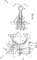
- a side view 700 and a plan view 702, respectively of the imaging system 100 with the display monitor 134 placed in a retracted position behind the C-arm 104 is disclosed.
- the display monitor 134 may be moved from the first side 512 of the C-arm 104 to the retracted position behind the C-arm 104 by rotating the articulating arm 130 via the elbow joint 128, and moving the display monitor 134 over the upper half of the C-shaped portion 105 from the first side of the C-arm 104 to the retracted position, without readjusting the position of the fixed arm 124.
- the articulating arm 130 may be reoriented by rotating the elbow joint 128 about the elbow rotational axis 168 in such a manner that the display monitor 134 is moved from the first side 512 of the C-arm 104 to the retracted position behind the C-arm 104.
- the elbow joint 128 may be adjusted such that the articulating arm 130 is moved from the first side 512 of the C-arm 104 to the retracted position behind the C-arm 104 while the fixed arm 124 is kept in a fixed position, for example, by engaging a brake (not shown) on the shoulder joint to lock the fixed arm 124.
- the fixed arm 124 When secured in the fixed position, the fixed arm 124 may be positioned at the angle 606 from the central axis 164 of the C-shaped portion 105 of the C-arm 104, as shown in FIG. 7B .
- the fixed arm 124 may be adjustable and may be moved from one position to another position when the articulating arm 130 is adjusted. After reorienting the elbow joint 128, the position of the articulating arm 130 may be adjusted such that the articulating arm 130 forms the angle 504 between the elbow axis 412 and arm center line 505, as shown in FIG.7A .
- the display monitor 134 may be adjusted to face a particular direction by adjusting the wrist joint 132 on one end of the articulating arm 130.
- the articulating arm 130 and display monitor 134 may be easily moved over the C-arm 104 and towards the second side 514 of the C-arm 104 without moving the display monitor 134 further behind from the C-arm 104.
- the fixed arm 124 and display monitor 134 never swing behind axis 510 while the display monitor is moving over the C-arm 104 from the first side 512 to the second side 514 of the C-arm.
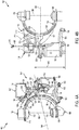
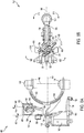
- a first side view 800, a first plan view 802, a second side view 804 and a second plan view 806, respectively of the imaging system 100 with the display monitor 134 positioned behind the C-arm 104 is disclosed.
- the display monitor 134 may be moved from the retracted position behind the C-arm 104 to a position where the display monitor 134 faces the first side 512 of the C-arm 104 by rotating the fixed arm 124 via the shoulder joint without readjusting the elbow joint 128 and articulating arm 130.
- the fixed arm 124 may be adjusted outward and away from the C-arm 104 via the shoulder joint 126 which is rotated about the shoulder axis 408, while the articulating arm 130 coupled to the elbow joint 128 may be maintained in a fixed position, as shown in FIGS. 8A-B .
- the fixed arm 124 may be positioned at an angle 808 defined between central axis 164 and an arm center line 810, as shown in FIG. 8B .
- the angle 808 may range from 0 to 120 degrees, when the position of the fixed arm 124 is adjusted to reorient the display monitor 134, for example.
- the display monitor 134 may be positioned behind the C-arm 104 at a location where the display monitor may be easily adjusted without being obstructed by the upper half of the C-shaped portion 105 of the C-arm 104.
- the center line 810 of the fixed arm 124 is aligned with the central axis 164 along the C-arm 104.
- the fixed arm 124 may be positioned in a skew direction from the central axis 164.
- the shoulder joint 126 may be rotatable about the shoulder axis 408 such that the display tablet 136 faces a particular direction, as shown in FIG. 8A .
- the shoulder joint 126 may be rotated to orient the display tablet 136 through a first angle 812 defined between the central axis 164 and axis 816 on a first side 820 of the cross member 120, and a second angle 814 defined between the central axis 164 and an axis 818 on a second side 822 of the cross member 120, as shown in FIG. 8B .
- the first angle 812 may range from 0 to 120 degrees
- the second angle 814 may range from 0 to -120 degrees, where each of the first angle 812 and second angle 814 is equal to zero degrees along the central 164.
- the fixed arm 124 may be further adjusted away from the C-arm 104 without readjusting the elbow joint 128 and articulating arm 130, as shown in FIG. 8C-D .
- the fixed arm 124 may be further adjusted away from the C-arm 104 and towards the second side 514 of the C-arm, such that the angle 808 is in a range of 0 - 120 degrees.
- the angle 808 is equal to zero degrees when the center line 810 of the fixed arm 124 is aligned with the central axis 164 and the elbow joint 128 is directly aligned with the C-arm 104 in a front position.
- the display monitor 134 may be placed in a position where the C-arm 104 does not obstruct movement of the articulating arm 130 when the display monitor 134 is reoriented.
- the shoulder joint 126 may be rotatable about the shoulder axis 408 to reorient the fixed arm 124 from the first side 512 of the C-arm 104 to the second side 514 of the C-arm 104 while the C-arm 104 remains fixed, the first side 512 arranged opposite the second side 514 relative to a central axis 164 arranged through a center of the C-shaped portion 105.
- a side view 900, and plan view 902, respectively of the imaging system 100 with the display monitor 134 facing the second side 514 of the C-arm 104 is disclosed.
- the display monitor 134 may be moved from behind the C-arm 104 to the second side 514 of the C-arm 104 by rotating the articulating arm 130 via the elbow joint 128 while the fixed arm 124 may be kept in a fixed position, for example by locking brakes (e.g., brake handle 122 shown in FIG. 1 ) on the shoulder joint 126.
- locking brakes e.g., brake handle 122 shown in FIG. 1
- the articulating arm 130 may be adjusted via the elbow joint 128 without readjusting the position of the fixed arm 124, as shown in FIG. 9A-B .
- the fixed arm 124 may be kept in the fixed position, such that the arm defines the angle 808 between central axis 164 and arm center line 810.
- the elbow joint 128 may be rotated about the elbow rotational axis 168, from a position where the display monitor 134 faces the upper half of the C-shaped portion 105 of the C-arm 104 to a different position where the display monitor 134 faces away from the C-arm 104 in the second side of the C-arm.
- the articulating arm 130 and display monitor 134 may be reoriented without the C-arm 104 causing any obstruction.
- the articulating arm 130 may be extended out past the C-arm 104, and the wrist joint 132 may be adjusted to orient the display monitor 134 in a direction facing the detector 108, as disclosed further below with reference to FIGS. 10A-B .
- the fixed arm 124 may be oriented in a position that allows the articulating arm 130 to be rotated via the elbow joint 128 to positions where the C-arm does not obstruct movement of the display monitor 134, when the monitor is moved from the first side 512 to the second side 514 of the C-arm 104.
- a side view 1000, and plan view 1002, respectively of the imaging system 100 with the display monitor 134 positioned in the second side 514 of the C-arm 104 is disclosed.
- the display monitor 134 may be extended forward and past the C-arm 104 to the second side 514 of the C-arm 104 by rotating the fixed arm 124 via the shoulder joint 126, and adjusting the articulating arm 130 via the elbow joint 128.
- the fixed arm 124 When the brake (not shown) on the shoulder joint 126 is disengaged, the fixed arm 124 may be moved forward and towards the C-arm 104.
- the fixed arm 124 may be positioned at the angle 808 formed between the central axis 164 and arm center line 810.
- the magnitude of the angle 808 may range from -15 to -45 degrees. In other examples, the magnitude of the angle 808 may range from 0 to -115 degrees.
- the articulating arm 130 may be adjusted by rotating the elbow joint 128 about the elbow rotational axis 168 in a direction away from the C-arm 104, and extending the articulating arm 130 forward in a horizontal direction, such that the arm makes an angle 1004 between the elbow axis 412 and arm center line 505.
- the wrist joint 132 may be adjusted to orient the display monitor 134 in a direction of the arrow 608 at the second side 514 of the C-arm 104, as shown in FIG. 10B .
- the display monitor 134 When positioned at the second side 514 of the C-arm 104, the display monitor 134 may be at a second distance 1006 from axis 612, adjacent to an operator (not shown) operating the imaging system 100.
- the second distance 1006 of the display monitor 134 from the axis 612 may be 337 cm.
- the second distance 1006 of the display monitor 134 from the axis 612 may range from 190 mm to 857 mm.
- the display monitor 134 may be moved through a plurality of distances that allow different operators to visually inspect images on the display monitor 134 with ease.
- the display monitor 134 may be reoriented by rotating the fixed arm 124 inward toward the C-arm 104 via the shoulder joint 126 while rotating the articulating arm 130 further inward and towards the C-arm 104 via the elbow joint 128 to move the display monitor 134 into the extended position on the second side 514 of the C-arm 104.
- a method 1100 for repositioning the display monitor (such as display monitor 134 shown in FIGS. 4A-10B ) coupled to an integrated arm (e.g., integrated arm 115 shown in FIGS.4A-B ) of an imaging system (e.g., system 100 shown in FIGS. 4A-10B ) from a first side of a C-arm (e.g., C-arm 104 shown in FIGS.4A-10B ) to a second side of the C-arm is disclosed.
- an integrated arm e.g., integrated arm 115 shown in FIGS.4A-B
- an imaging system e.g., system 100 shown in FIGS. 4A-10B
- the method 1100 includes moving the display monitor from a parked position to an unlocked position behind the C-arm.
- the monitor When the imaging system is placed in the parked position, the monitor may be placed in a pocket (e.g., pocket 404 shown in FIG.4A ).
- the display monitor When in the parked position, the display monitor may be positioned behind the C-arm at a height that allows the imaging system to be transported with ease. In this case, the imaging system may be transported from one position to another by rolling the system using the plurality of the wheels coupled to a lower portion of a base unit that supports the C-arm and integrated arm coupled to the display monitor.
- the display monitor When the imaging system is activated, the display monitor may be adjusted from the parked position to the unlocked position by moving the articulating arm upward while the elbow joint and fixed arm remain in fixed positions.
- the elbow joint couples the articulating arm which is coupled directly to the display monitor, and to a curved portion of the fixed arm, where the fixed arm may couple the articulating arm to the C-arm.
- a height of the display monitor When moved from the parked position to the unlocked position behind the C-arm, a height of the display monitor may increase, thereby creating more space for maneuvering the integrated arm and display monitor.
- a brake on the shoulder joint may be unlocked to allow the fixed arm to move freely. In this case, only a single brake may be provide on the integrated arm to expedite adjusting of the display monitor before or during imaging operations.
- a wrist joint (e.g., wrist joint 132 shown in FIGS.5A-B ), on one end of the articulating arm coupling the display monitor, may be adjusted to orient the display monitor in a
- the display monitor may be moved from the unlocked position behind the C-arm to the first side of the C-arm.
- the display monitor may be moved from behind the C-arm to the first side of the C-arm by rotating the fixed arm via the shoulder joint, and adjusting the articulating arm via the elbow joint.
- the fixed arm may be moved from a position where a straight portion (e.g., portion 125 shown in FIG. 5B ) of the arm lies along a central axis (e.g., axis 164 shown in FIG. 5B ) of the C-arm, to a position where the fixed arm lies along an arm center line that defines an angle (e.g., angle 606 shown in FIG. 6B ) with the central axis of the C-arm.
- the shoulder joint may include a brake adapted to lock rotation of the shoulder joint.
- the fixed arm may be locked into a fixed position while allowing the articulating arm to rotate via the elbow joint.
- the elbow joint may be rotated from a first position where the elbow joint faces away from the C-arm to a second position where the elbow joint faces an upper half of the C-shaped portion of the C-arm.
- the articulating arm may be rotated (via the elbow joint) to face the upper half of the C-shaped portion of the C-arm, and extended forward and toward the first side of the C-arm.
- the display monitor may be reoriented by rotating the fixed arm inward toward the C-arm via the shoulder joint while rotating the articulating arm further inward and towards the C-arm via the elbow joint to move the display monitor into an extended position on the first side of the C-arm.
- the articulating arm may be adapted to pivot at the elbow joint, while the wrist joint on one end of the articulating arm may be adjusted such that the display monitor faces a direction of an operator using the imaging system.
- the display monitor When positioned at the first side of the C-arm, the display monitor may be positioned at a threshold distance that allows the operator the ability to visually inspect images on the display monitor with ease.
- the method 1100 may include rotating the display monitor from the extended position on the first side of the C-arm, over the C-arm and towards a retracted position behind the C-arm via the elbow joint.
- the display monitor may be moved from the first side of the C-arm to towards the retracted position with less difficulty.
- the fixed arm may remain in a fixed position when the display monitor is moved from the first side of the C-arm to the retracted position.
- the method 1100 may include adjusting both the shoulder joint and elbow joint to move the display monitor from the retracted position into an extended position on the second side of the C-arm.
- the extended position on the second side of the C-arm may include the display monitor being positioned away from a base unit (e.g., base unit 102 shown in FIGS. 10A-B ) of the imaging system.
- the fixed arm may be extended to the second side of the C-arm via the shoulder joint that couples a straight portion of the fixed arm to the C-arm. The straight portion also couples to the curved portion of the fixed arm.
- the display monitor may be moved from the first side of the C-arm to the second side of the C-arm by moving the monitor over the top half of the C-shaped portion of the C-arm without swinging the monitor around a back side of the base unit coupled to the C-arm.
- the display monitor may be expeditiously reoriented from one position to another using the integrated arm comprising the fixed arm coupled to the shoulder joint, and the articulating arm coupled on one end to the fixed arm via the elbow joint, and coupled at another end to the display monitor via the wrist joint. The method then exits.
- FIGS. 1-10B show example configurations with relative positioning of the various components of the imaging system. If shown directly contacting each other, or directly coupled, then such elements may be referred to as directly contacting or directly coupled, respectively, at least in one example. Similarly, elements shown contiguous or adjacent to one another may be contiguous or adjacent to each other, respectively, at least in one example. As an example, components laying in face-sharing contact with each other may be referred to as in face-sharing contact. As another example, elements positioned apart from each other with only a space therebetween and no other components may be referred to as such, in at least one example.
- top/bottom, upper/lower, above/below may be relative to a vertical axis of the figures and used to describe positioning of elements of the figures relative to one another.
- elements shown above other elements are positioned vertically above the other elements, in one example.
- shapes of the elements depicted within the figures may be referred to as having those shapes (e.g., such as being circular, straight, planar, curved, rounded, chamfered, angled, or the like).
- elements shown intersecting one another may be referred to as intersecting elements or intersecting one another, in at least one example.
- an element shown within another element or shown outside of another element may be referred as such, in one example.
- the technical effect of the disclosure may include improved mobility of the integrated arm coupled to the display monitor of the imaging system, where the display monitor may be easily moved from a first position to a second position without causing undue difficulty to an operator of the imaging system. Adjusting the display monitor from the first position to the second position involves moving the monitor over the top of the C-arm (instead of via the back end of the C-arm) to expedite the adjusting of the display monitor during imaging operations.
- the integrated arm of the imaging system may include only a single brake on the shoulder joint (instead of a plurality of brakes), thereby allowing the integrated arm to be quickly adjusted to reorient the display monitor without requiring undue effort from the operator.
- Another technical effect of the disclosure may include improved flexibility of the integrated arm where a height of the display monitor and a distance of the monitor from the operator may be adjustable to suit needs of different operators and various imaging procedures.
- Yet another technical effect of the disclosure may include improved flexibility of the C-arm during imaging operations.
- the C-arm may be adjustable via the rotational joint that couples C-arm to the base unit.
- the x-ray source and detector coupled on opposite sides of the C-arm may be adjusted through a plurality of positions to capture multiple images of a patient's body without moving or repositioning the patient.
- a further technical effect of the disclosure may include improved operation of the imaging system, since a single brake may be provided on the integrated arm, thereby allowing the display monitor to be reoriented expeditiously without spending time unlocking and locking different brake systems.
- an imaging system may comprise: a base unit; a C-arm coupled to the base unit and including an x-ray source and detector positioned on opposite ends of a C-shaped portion of the C-arm; and a display monitor attached to the C-arm via an integrated arm, wherein the display monitor is movable between a first position on a first side of the C-arm, to a second position on a second side of the C-arm by traveling over a top of an upper half of the C-shaped portion.
Landscapes
- Health & Medical Sciences (AREA)
- Life Sciences & Earth Sciences (AREA)
- Engineering & Computer Science (AREA)
- Medical Informatics (AREA)
- Radiology & Medical Imaging (AREA)
- Molecular Biology (AREA)
- Biophysics (AREA)
- Nuclear Medicine, Radiotherapy & Molecular Imaging (AREA)
- Optics & Photonics (AREA)
- Pathology (AREA)
- Physics & Mathematics (AREA)
- Biomedical Technology (AREA)
- Heart & Thoracic Surgery (AREA)
- High Energy & Nuclear Physics (AREA)
- Surgery (AREA)
- Animal Behavior & Ethology (AREA)
- General Health & Medical Sciences (AREA)
- Public Health (AREA)
- Veterinary Medicine (AREA)
- Human Computer Interaction (AREA)
- Apparatus For Radiation Diagnosis (AREA)
- Analysing Materials By The Use Of Radiation (AREA)
Claims (13)
- Bildgebungssystem (100), umfassend:eine Basiseinheit (102), umfassend ein Querelement (120) ;einen C-Bogen (104), der an einem ausgezogenen Abschnitt (107) des C-Bogens an die Basiseinheit gekoppelt ist, wobei der ausgezogene Abschnitt über ein drehbares Gelenk (109) an das Querelement gekoppelt ist, und einschließend eine Röntgenquelle (106) und einen Detektor (108), die an entgegengesetzten Enden des C-förmigen Abschnitts (105) des C-Bogens positioniert sind;einen fixierten Arm (124), der durch das Querelement und das drehbare Gelenk direkt an den ausgezogenen Abschnitt des C-Bogens gekoppelt ist und zwei Gelenke (126; 128) einschließt, die voneinander versetzt sind, wobei ein erstes Gelenk (126) der beiden Gelenke sich an dem Querelement befindet;einen gelenkig verbundenen Arm (130), der an einem zweiten Gelenk (128) der beiden Gelenke des fixierten Arms an den fixierten Arm gekoppelt ist; undeinen Anzeigemonitor (130), der über ein drittes Gelenk (132) an ein Ende des gelenkig verbundenen Arms gekoppelt ist.
- Bildgebungssystem nach Anspruch 1, wobei die drei Gelenke zueinander beweglich und voneinander versetzt sind.
- Bildgebungssystem nach Anspruch 1 oder Anspruch 2, wobei der fixierte Arm und der gelenkig verbundene Arm mittels eines Ellbogengelenks (128) aneinander gekoppelt sind.
- Bildgebungssystem nach Anspruch 3, wobei der fixierte Arm zwei Versatzgelenke einschließt, die das Ellbogengelenk (128) und ein Schultergelenk (126) einschließen, die an entgegengesetzten Enden des fixierten Arms angeordnet sind, wobei das Schultergelenk der beiden Versatzgelenke einen geraden Abschnitt (125) des fixierten Arms an den C-Bogen koppelt und das Ellbogengelenk der beiden Versatzgelenke einen gekrümmten Abschnitt (127) des fixierten Arms an den gelenkig verbundenen Arm koppelt.
- Bildgebungssystem nach Anspruch 4, wobei der gekrümmte Abschnitt des fixierten Arms einem Krümmungsradius einer oberen Hälfte des C-förmigen Abschnitts des C-Bogens folgt, und wobei der gekrümmte Abschnitt des fixierten Arms sich entlang eines Abschnitts der oberen Hälfte des C-förmigen Abschnitts des C-Bogens, jedoch versetzt dazu krümmt, wenn sich der Anzeigemonitor und der integrierte Arm in einer geparkten Position befinden.
- Bildgebungssystem nach einem der Ansprüche 4 und 5, des Weiteren umfassend eine Einzelbremse, die an das Schultergelenk gekoppelt ist und vorgesehen ist, um die Rotation des Schultergelenks zu arretieren, und wobei das Ellbogengelenk keine Bremse einschließt.
- Bildgebungssystem nach einem der Ansprüche 3 bis 6, wobei der gelenkig verbundene Arm vorgesehen ist, um an dem Ellbogengelenk zu schwenken, und wobei der gelenkig verbundene Arm mittels eines Handgelenks (132) an den Anzeigemonitor gekoppelt ist.
- Bildgebungssystem nach einem der vorhergehenden Ansprüche, wobei der C-förmige Abschnitt vorgesehen ist, um in jeder Richtung mittels des drehbaren Gelenks, welches den C-förmigen Abschnitt an den ausgezogenen Abschnitt des C-Bogens koppelt, um mindestens 180 Grad zu rotieren.
- Bildgebungssystem nach einem der vorhergehenden Ansprüche, des Weiteren umfassend eine Tasche (404), die vorgesehen ist, um den Anzeigemonitor aufzunehmen, wenn das Bildgebungssystem in einer geparkten Position platziert wird.
- Bildgebungssystem nach einem der Ansprüche 4 bis 9, des Weiteren umfassend ein Anzeige-Tablet (136), das an ein vertikales Element gekoppelt ist, welches an dem Schultergelenk befestigt ist.
- Bildgebungssystem nach einem der vorhergehenden Ansprüche, wobei die Basiseinheit mittels einer Vielzahl von Rädern (160) beweglich ist, die an einen Boden der Basiseinheit gekoppelt sind.
- Bildgebungssystem nach einem der vorhergehenden Ansprüche, wobei der Anzeigemonitor zwischen einer ersten Position auf einer ersten Seite des C-Bogens und einer zweiten Position auf einer zweiten Seite des C-Bogens bewegbar ist, indem er über einen obersten Bereich einer oberen Hälfte des C-förmigen Abschnitts hinweg bewegt wird.
- Verfahren zur Manipulation des Bildgebungssystems nach Anspruch 1, wobei das Verfahren umfasst:Drehen des Anzeigemonitors aus einer ausgezogenen Position auf einer ersten Seite des C-Arms zu einer zurückgezogenen Position hinter dem C-Arm mittels eines Ellbogengelenks (128) als zweites Gelenk, welches den gelenkig verbundenen Arm an einen gekrümmten Abschnitt des fixierten Arms koppelt;Drehen des gelenkig verbundenen Arms über eine obere Hälfte des C-förmigen Abschnitts des C-Bogens hinweg und auf eine zweite Seite des C-Bogens mittels eines Schultergelenks (126) als erstes Gelenk, welches einen geraden Abschnitt des fixierten Arms an den C-Bogen koppelt, wobei der gerade Abschnitt an den gekrümmten Abschnitt gekoppelt ist; undAnpassen von sowohl dem Ellbogengelenk als auch dem Schultergelenk, um den Anzeigemonitor auf der zweiten Seite des C-Bogens in eine ausgezogene Position zu bewegen, wobei die ausgezogene Position auf jeder von der ersten und der zweiten Seite einschließt, dass der Anzeigemonitor von der Basiseinheit des Bildgebungssystems weg positioniert wird.
Applications Claiming Priority (1)
| Application Number | Priority Date | Filing Date | Title |
|---|---|---|---|
| US15/489,643 US10485499B2 (en) | 2017-04-17 | 2017-04-17 | Method and systems for a compact integrated monitor arm for an imaging system |
Publications (2)
| Publication Number | Publication Date |
|---|---|
| EP3391822A1 EP3391822A1 (de) | 2018-10-24 |
| EP3391822B1 true EP3391822B1 (de) | 2020-05-27 |
Family
ID=62002545
Family Applications (1)
| Application Number | Title | Priority Date | Filing Date |
|---|---|---|---|
| EP18167506.7A Active EP3391822B1 (de) | 2017-04-17 | 2018-04-16 | Verfahren und systeme für einen kompakten integrierten monitorarm für ein bildgebungssystem |
Country Status (4)
| Country | Link |
|---|---|
| US (1) | US10485499B2 (de) |
| EP (1) | EP3391822B1 (de) |
| JP (1) | JP6775543B2 (de) |
| CN (1) | CN108836372B (de) |
Families Citing this family (11)
| Publication number | Priority date | Publication date | Assignee | Title |
|---|---|---|---|---|
| WO2020069122A1 (en) | 2018-09-28 | 2020-04-02 | Hologic, Inc. | Mini c-arm with increased range of motion |
| CN109806002B (zh) * | 2019-01-14 | 2021-02-23 | 微创(上海)医疗机器人有限公司 | 一种手术机器人 |
| USD919090S1 (en) | 2019-03-04 | 2021-05-11 | GE Precision Healthcare LLC | Imaging apparatus |
| JP7220801B2 (ja) | 2019-10-31 | 2023-02-10 | 富士フイルム株式会社 | 移動型放射線撮影装置 |
| JP7674135B2 (ja) * | 2021-04-15 | 2025-05-09 | 富士フイルム株式会社 | 移動型放射線撮影装置 |
| CN113197593A (zh) * | 2021-06-21 | 2021-08-03 | 深圳市深图医学影像设备有限公司 | 一种可移动小型化cbct设备 |
| CN113984796A (zh) * | 2021-10-21 | 2022-01-28 | 俐玛光电科技(北京)有限公司 | 有限角度扫描检测装置 |
| GB2618829A (en) * | 2022-05-19 | 2023-11-22 | Adaptix Ltd | An x-ray imaging apparatus |
| CN218738969U (zh) * | 2022-08-22 | 2023-03-28 | 上海西门子医疗器械有限公司 | 旋转制动机构、c形臂x射线机及其监控器支架 |
| JP2025073458A (ja) * | 2023-10-26 | 2025-05-13 | 富士フイルム株式会社 | マンモグラフィ装置、マンモグラフィ装置の表示方法、及び医用画像取得システム |
| USD1098440S1 (en) * | 2024-04-04 | 2025-10-14 | GE Precision Healthcare LLC | Imaging apparatus |
Family Cites Families (15)
| Publication number | Priority date | Publication date | Assignee | Title |
|---|---|---|---|---|
| US5627873B1 (en) | 1995-08-04 | 2000-03-14 | Oec Medical Systems | Mini c-arm assembly for mobile x-ray imaging system |
| DE19625407C2 (de) * | 1996-06-25 | 2000-03-23 | Siemens Ag | Röntgenuntersuchungseinrichtung |
| JPH11299766A (ja) * | 1998-04-24 | 1999-11-02 | Toshiba Medical Seizo Kk | X線診断装置 |
| AU1210100A (en) | 1998-10-19 | 2000-05-08 | Fluoroscan Imaging Systems, Inc. | Miniature c-arm apparatus with dual monitor system and single driver interface therefor |
| US6343006B1 (en) | 1998-11-20 | 2002-01-29 | Jerry Moscovitch | Computer display screen system and adjustable screen mount, and swinging screens therefor |
| JP4266382B2 (ja) * | 2006-07-18 | 2009-05-20 | アロカ株式会社 | 超音波診断装置 |
| JP4841415B2 (ja) * | 2006-12-11 | 2011-12-21 | ジーイー・メディカル・システムズ・グローバル・テクノロジー・カンパニー・エルエルシー | 表示部支持アームおよび超音波撮像装置 |
| DE102007052650B4 (de) * | 2007-11-05 | 2016-11-03 | Siemens Healthcare Gmbh | Bildgebendes System und Verfahren zum Betrieb eines bildgebenden Systems |
| ES2659090T3 (es) | 2009-03-20 | 2018-03-13 | Orthoscan Incorporated | Aparato móvil de captación de imagen |
| JP2011115364A (ja) | 2009-12-03 | 2011-06-16 | Hitachi Medical Corp | X線診断装置 |
| EP2580513A1 (de) | 2010-06-09 | 2013-04-17 | Innovative Office Products, Inc. | Monitorgelenkarm mit kabel und feder |
| FR2962638B1 (fr) * | 2010-07-15 | 2013-03-15 | Gen Electric | Systeme d'imagerie deplacable comprenant des moyens d'affichage integres |
| JP6176832B2 (ja) * | 2013-04-18 | 2017-08-09 | 東芝メディカルシステムズ株式会社 | 支持器及びx線診断装置 |
| DE102013013552B3 (de) * | 2013-08-14 | 2014-07-03 | Ziehm Imaging Gmbh | Verfahren zur Aufnahme eines in der Zentralschicht vollständigen Projektionsdatensatzes zur CT- Rekonstruktion unter Verwendung eines C-Bogen-Röntgengeräts mit einem begrenzten Rotationsbereich |
| EP3042549A4 (de) | 2013-09-03 | 2017-04-26 | Swissray Asia Healthcare Co., Ltd. | Gelenkige anzeige für eine mobile radiografische maschine |
-
2017
- 2017-04-17 US US15/489,643 patent/US10485499B2/en active Active
-
2018
- 2018-04-16 EP EP18167506.7A patent/EP3391822B1/de active Active
- 2018-04-16 JP JP2018078259A patent/JP6775543B2/ja active Active
- 2018-04-17 CN CN201810343898.0A patent/CN108836372B/zh active Active
Non-Patent Citations (1)
| Title |
|---|
| None * |
Also Published As
| Publication number | Publication date |
|---|---|
| CN108836372B (zh) | 2022-05-27 |
| JP2018175873A (ja) | 2018-11-15 |
| US20180296174A1 (en) | 2018-10-18 |
| CN108836372A (zh) | 2018-11-20 |
| JP6775543B2 (ja) | 2020-10-28 |
| EP3391822A1 (de) | 2018-10-24 |
| US10485499B2 (en) | 2019-11-26 |
Similar Documents
| Publication | Publication Date | Title |
|---|---|---|
| US10485499B2 (en) | Method and systems for a compact integrated monitor arm for an imaging system | |
| CN111207282B (zh) | 用于可枢转平板电脑支架的方法和系统 | |
| US7741623B2 (en) | Patient positioning device | |
| CN110478036B (zh) | 用于集成手术台的系统和方法 | |
| US5515416A (en) | Bi-plane imaging device | |
| KR102460203B1 (ko) | 통합 수술 테이블 아이콘을 위한 시스템 및 방법 | |
| US8992082B2 (en) | G-arm X-ray imaging apparatus | |
| JP7127968B2 (ja) | 関節運動カメラスタンド | |
| EP3342389B1 (de) | Robotischer operationstisch und hybrides operationssystem | |
| US7298821B2 (en) | Imaging and treatment system | |
| US10517553B2 (en) | C-arm imaging system with multiple automated independent rotational axes | |
| EP3741345A1 (de) | System zur bewegung eines integrierten operationstisches | |
| EP2502561B1 (de) | Bogenförmige medizinische Abbildungsausrüstung | |
| EP3534795B1 (de) | Medizinische bildgebungsvorrichtung | |
| CN113133782A (zh) | 移动式平台和包括多个移动式平台的系统 | |
| US10741296B2 (en) | Imaging table and radiation imaging system | |
| EP2407108B1 (de) | Bewegliches Abbildungssystem mit integrierten Anzeigemitteln | |
| US20250114059A1 (en) | System for performing robotic surgery | |
| CN106714691A (zh) | 移动的x射线设备 | |
| US11369325B2 (en) | Advanced concept mobile X-ray imaging device | |
| US9782139B2 (en) | X-ray device | |
| EP3815742A1 (de) | Strahlentherapievorrichtung, abbildungsring umfassend | |
| US12290396B2 (en) | Cable management clamp and method for securing cables in C-arm imaging systems | |
| FI3111845T3 (fi) | Menetelmä ja laite volumetristen panoraama- ja CBCT-röntgenkuvien ottamiseksi | |
| Kim et al. | Design and development of a mobile robotic CT system for intraoperative use |
Legal Events
| Date | Code | Title | Description |
|---|---|---|---|
| PUAI | Public reference made under article 153(3) epc to a published international application that has entered the european phase |
Free format text: ORIGINAL CODE: 0009012 |
|
| STAA | Information on the status of an ep patent application or granted ep patent |
Free format text: STATUS: THE APPLICATION HAS BEEN PUBLISHED |
|
| AK | Designated contracting states |
Kind code of ref document: A1 Designated state(s): AL AT BE BG CH CY CZ DE DK EE ES FI FR GB GR HR HU IE IS IT LI LT LU LV MC MK MT NL NO PL PT RO RS SE SI SK SM TR |
|
| AX | Request for extension of the european patent |
Extension state: BA ME |
|
| STAA | Information on the status of an ep patent application or granted ep patent |
Free format text: STATUS: REQUEST FOR EXAMINATION WAS MADE |
|
| 17P | Request for examination filed |
Effective date: 20190416 |
|
| RBV | Designated contracting states (corrected) |
Designated state(s): AL AT BE BG CH CY CZ DE DK EE ES FI FR GB GR HR HU IE IS IT LI LT LU LV MC MK MT NL NO PL PT RO RS SE SI SK SM TR |
|
| GRAP | Despatch of communication of intention to grant a patent |
Free format text: ORIGINAL CODE: EPIDOSNIGR1 |
|
| STAA | Information on the status of an ep patent application or granted ep patent |
Free format text: STATUS: GRANT OF PATENT IS INTENDED |
|
| GRAJ | Information related to disapproval of communication of intention to grant by the applicant or resumption of examination proceedings by the epo deleted |
Free format text: ORIGINAL CODE: EPIDOSDIGR1 |
|
| STAA | Information on the status of an ep patent application or granted ep patent |
Free format text: STATUS: REQUEST FOR EXAMINATION WAS MADE |
|
| INTG | Intention to grant announced |
Effective date: 20191125 |
|
| INTC | Intention to grant announced (deleted) | ||
| GRAP | Despatch of communication of intention to grant a patent |
Free format text: ORIGINAL CODE: EPIDOSNIGR1 |
|
| STAA | Information on the status of an ep patent application or granted ep patent |
Free format text: STATUS: GRANT OF PATENT IS INTENDED |
|
| INTG | Intention to grant announced |
Effective date: 20200212 |
|
| RIN1 | Information on inventor provided before grant (corrected) |
Inventor name: ALDER, SAMUEL LEE Inventor name: LIU, MINGTAO Inventor name: BARKER, DAVID ELLIS Inventor name: PENG, CONG |
|
| GRAS | Grant fee paid |
Free format text: ORIGINAL CODE: EPIDOSNIGR3 |
|
| GRAA | (expected) grant |
Free format text: ORIGINAL CODE: 0009210 |
|
| STAA | Information on the status of an ep patent application or granted ep patent |
Free format text: STATUS: THE PATENT HAS BEEN GRANTED |
|
| AK | Designated contracting states |
Kind code of ref document: B1 Designated state(s): AL AT BE BG CH CY CZ DE DK EE ES FI FR GB GR HR HU IE IS IT LI LT LU LV MC MK MT NL NO PL PT RO RS SE SI SK SM TR |
|
| REG | Reference to a national code |
Ref country code: GB Ref legal event code: FG4D |
|
| REG | Reference to a national code |
Ref country code: CH Ref legal event code: EP |
|
| REG | Reference to a national code |
Ref country code: AT Ref legal event code: REF Ref document number: 1273675 Country of ref document: AT Kind code of ref document: T Effective date: 20200615 |
|
| REG | Reference to a national code |
Ref country code: DE Ref legal event code: R096 Ref document number: 602018004824 Country of ref document: DE |
|
| REG | Reference to a national code |
Ref country code: NL Ref legal event code: FP |
|
| REG | Reference to a national code |
Ref country code: LT Ref legal event code: MG4D |
|
| PG25 | Lapsed in a contracting state [announced via postgrant information from national office to epo] |
Ref country code: IS Free format text: LAPSE BECAUSE OF FAILURE TO SUBMIT A TRANSLATION OF THE DESCRIPTION OR TO PAY THE FEE WITHIN THE PRESCRIBED TIME-LIMIT Effective date: 20200927 Ref country code: PT Free format text: LAPSE BECAUSE OF FAILURE TO SUBMIT A TRANSLATION OF THE DESCRIPTION OR TO PAY THE FEE WITHIN THE PRESCRIBED TIME-LIMIT Effective date: 20200928 Ref country code: FI Free format text: LAPSE BECAUSE OF FAILURE TO SUBMIT A TRANSLATION OF THE DESCRIPTION OR TO PAY THE FEE WITHIN THE PRESCRIBED TIME-LIMIT Effective date: 20200527 Ref country code: NO Free format text: LAPSE BECAUSE OF FAILURE TO SUBMIT A TRANSLATION OF THE DESCRIPTION OR TO PAY THE FEE WITHIN THE PRESCRIBED TIME-LIMIT Effective date: 20200827 Ref country code: GR Free format text: LAPSE BECAUSE OF FAILURE TO SUBMIT A TRANSLATION OF THE DESCRIPTION OR TO PAY THE FEE WITHIN THE PRESCRIBED TIME-LIMIT Effective date: 20200828 Ref country code: SE Free format text: LAPSE BECAUSE OF FAILURE TO SUBMIT A TRANSLATION OF THE DESCRIPTION OR TO PAY THE FEE WITHIN THE PRESCRIBED TIME-LIMIT Effective date: 20200527 Ref country code: LT Free format text: LAPSE BECAUSE OF FAILURE TO SUBMIT A TRANSLATION OF THE DESCRIPTION OR TO PAY THE FEE WITHIN THE PRESCRIBED TIME-LIMIT Effective date: 20200527 |
|
| PG25 | Lapsed in a contracting state [announced via postgrant information from national office to epo] |
Ref country code: BG Free format text: LAPSE BECAUSE OF FAILURE TO SUBMIT A TRANSLATION OF THE DESCRIPTION OR TO PAY THE FEE WITHIN THE PRESCRIBED TIME-LIMIT Effective date: 20200827 Ref country code: HR Free format text: LAPSE BECAUSE OF FAILURE TO SUBMIT A TRANSLATION OF THE DESCRIPTION OR TO PAY THE FEE WITHIN THE PRESCRIBED TIME-LIMIT Effective date: 20200527 Ref country code: LV Free format text: LAPSE BECAUSE OF FAILURE TO SUBMIT A TRANSLATION OF THE DESCRIPTION OR TO PAY THE FEE WITHIN THE PRESCRIBED TIME-LIMIT Effective date: 20200527 Ref country code: RS Free format text: LAPSE BECAUSE OF FAILURE TO SUBMIT A TRANSLATION OF THE DESCRIPTION OR TO PAY THE FEE WITHIN THE PRESCRIBED TIME-LIMIT Effective date: 20200527 |
|
| REG | Reference to a national code |
Ref country code: AT Ref legal event code: MK05 Ref document number: 1273675 Country of ref document: AT Kind code of ref document: T Effective date: 20200527 |
|
| PG25 | Lapsed in a contracting state [announced via postgrant information from national office to epo] |
Ref country code: AL Free format text: LAPSE BECAUSE OF FAILURE TO SUBMIT A TRANSLATION OF THE DESCRIPTION OR TO PAY THE FEE WITHIN THE PRESCRIBED TIME-LIMIT Effective date: 20200527 |
|
| PG25 | Lapsed in a contracting state [announced via postgrant information from national office to epo] |
Ref country code: AT Free format text: LAPSE BECAUSE OF FAILURE TO SUBMIT A TRANSLATION OF THE DESCRIPTION OR TO PAY THE FEE WITHIN THE PRESCRIBED TIME-LIMIT Effective date: 20200527 Ref country code: ES Free format text: LAPSE BECAUSE OF FAILURE TO SUBMIT A TRANSLATION OF THE DESCRIPTION OR TO PAY THE FEE WITHIN THE PRESCRIBED TIME-LIMIT Effective date: 20200527 Ref country code: DK Free format text: LAPSE BECAUSE OF FAILURE TO SUBMIT A TRANSLATION OF THE DESCRIPTION OR TO PAY THE FEE WITHIN THE PRESCRIBED TIME-LIMIT Effective date: 20200527 Ref country code: IT Free format text: LAPSE BECAUSE OF FAILURE TO SUBMIT A TRANSLATION OF THE DESCRIPTION OR TO PAY THE FEE WITHIN THE PRESCRIBED TIME-LIMIT Effective date: 20200527 Ref country code: RO Free format text: LAPSE BECAUSE OF FAILURE TO SUBMIT A TRANSLATION OF THE DESCRIPTION OR TO PAY THE FEE WITHIN THE PRESCRIBED TIME-LIMIT Effective date: 20200527 Ref country code: CZ Free format text: LAPSE BECAUSE OF FAILURE TO SUBMIT A TRANSLATION OF THE DESCRIPTION OR TO PAY THE FEE WITHIN THE PRESCRIBED TIME-LIMIT Effective date: 20200527 Ref country code: EE Free format text: LAPSE BECAUSE OF FAILURE TO SUBMIT A TRANSLATION OF THE DESCRIPTION OR TO PAY THE FEE WITHIN THE PRESCRIBED TIME-LIMIT Effective date: 20200527 Ref country code: SM Free format text: LAPSE BECAUSE OF FAILURE TO SUBMIT A TRANSLATION OF THE DESCRIPTION OR TO PAY THE FEE WITHIN THE PRESCRIBED TIME-LIMIT Effective date: 20200527 |
|
| PG25 | Lapsed in a contracting state [announced via postgrant information from national office to epo] |
Ref country code: PL Free format text: LAPSE BECAUSE OF FAILURE TO SUBMIT A TRANSLATION OF THE DESCRIPTION OR TO PAY THE FEE WITHIN THE PRESCRIBED TIME-LIMIT Effective date: 20200527 Ref country code: SK Free format text: LAPSE BECAUSE OF FAILURE TO SUBMIT A TRANSLATION OF THE DESCRIPTION OR TO PAY THE FEE WITHIN THE PRESCRIBED TIME-LIMIT Effective date: 20200527 |
|
| REG | Reference to a national code |
Ref country code: DE Ref legal event code: R097 Ref document number: 602018004824 Country of ref document: DE |
|
| PLBE | No opposition filed within time limit |
Free format text: ORIGINAL CODE: 0009261 |
|
| STAA | Information on the status of an ep patent application or granted ep patent |
Free format text: STATUS: NO OPPOSITION FILED WITHIN TIME LIMIT |
|
| 26N | No opposition filed |
Effective date: 20210302 |
|
| PG25 | Lapsed in a contracting state [announced via postgrant information from national office to epo] |
Ref country code: SI Free format text: LAPSE BECAUSE OF FAILURE TO SUBMIT A TRANSLATION OF THE DESCRIPTION OR TO PAY THE FEE WITHIN THE PRESCRIBED TIME-LIMIT Effective date: 20200527 |
|
| PG25 | Lapsed in a contracting state [announced via postgrant information from national office to epo] |
Ref country code: MC Free format text: LAPSE BECAUSE OF FAILURE TO SUBMIT A TRANSLATION OF THE DESCRIPTION OR TO PAY THE FEE WITHIN THE PRESCRIBED TIME-LIMIT Effective date: 20200527 |
|
| PG25 | Lapsed in a contracting state [announced via postgrant information from national office to epo] |
Ref country code: LU Free format text: LAPSE BECAUSE OF NON-PAYMENT OF DUE FEES Effective date: 20210416 |
|
| REG | Reference to a national code |
Ref country code: BE Ref legal event code: MM Effective date: 20210430 |
|
| PG25 | Lapsed in a contracting state [announced via postgrant information from national office to epo] |
Ref country code: CH Free format text: LAPSE BECAUSE OF NON-PAYMENT OF DUE FEES Effective date: 20210430 Ref country code: LI Free format text: LAPSE BECAUSE OF NON-PAYMENT OF DUE FEES Effective date: 20210430 |
|
| PG25 | Lapsed in a contracting state [announced via postgrant information from national office to epo] |
Ref country code: IE Free format text: LAPSE BECAUSE OF NON-PAYMENT OF DUE FEES Effective date: 20210416 |
|
| PG25 | Lapsed in a contracting state [announced via postgrant information from national office to epo] |
Ref country code: BE Free format text: LAPSE BECAUSE OF NON-PAYMENT OF DUE FEES Effective date: 20210430 |
|
| PG25 | Lapsed in a contracting state [announced via postgrant information from national office to epo] |
Ref country code: CY Free format text: LAPSE BECAUSE OF FAILURE TO SUBMIT A TRANSLATION OF THE DESCRIPTION OR TO PAY THE FEE WITHIN THE PRESCRIBED TIME-LIMIT Effective date: 20200527 |
|
| P01 | Opt-out of the competence of the unified patent court (upc) registered |
Effective date: 20230528 |
|
| PG25 | Lapsed in a contracting state [announced via postgrant information from national office to epo] |
Ref country code: HU Free format text: LAPSE BECAUSE OF FAILURE TO SUBMIT A TRANSLATION OF THE DESCRIPTION OR TO PAY THE FEE WITHIN THE PRESCRIBED TIME-LIMIT; INVALID AB INITIO Effective date: 20180416 |
|
| PG25 | Lapsed in a contracting state [announced via postgrant information from national office to epo] |
Ref country code: MK Free format text: LAPSE BECAUSE OF FAILURE TO SUBMIT A TRANSLATION OF THE DESCRIPTION OR TO PAY THE FEE WITHIN THE PRESCRIBED TIME-LIMIT Effective date: 20200527 |
|
| PG25 | Lapsed in a contracting state [announced via postgrant information from national office to epo] |
Ref country code: MT Free format text: LAPSE BECAUSE OF FAILURE TO SUBMIT A TRANSLATION OF THE DESCRIPTION OR TO PAY THE FEE WITHIN THE PRESCRIBED TIME-LIMIT Effective date: 20200527 |
|
| REG | Reference to a national code |
Ref country code: NL Ref legal event code: PD Owner name: GE PRECISION HEALTHCARE LLC; US Free format text: DETAILS ASSIGNMENT: CHANGE OF OWNER(S), ASSIGNMENT; FORMER OWNER NAME: GENERAL ELECTRIC COMPANY Effective date: 20250604 |
|
| PGFP | Annual fee paid to national office [announced via postgrant information from national office to epo] |
Ref country code: DE Payment date: 20250319 Year of fee payment: 8 |
|
| REG | Reference to a national code |
Ref country code: DE Ref legal event code: R081 Ref document number: 602018004824 Country of ref document: DE Owner name: GE PRECISION HEALTHCARE LLC, WAUKESHA, US Free format text: FORMER OWNER: GENERAL ELECTRIC COMPANY, SCHENECTADY, NY, US |
|
| REG | Reference to a national code |
Ref country code: GB Ref legal event code: 732E Free format text: REGISTERED BETWEEN 20250807 AND 20250813 |
|
| PG25 | Lapsed in a contracting state [announced via postgrant information from national office to epo] |
Ref country code: TR Free format text: LAPSE BECAUSE OF FAILURE TO SUBMIT A TRANSLATION OF THE DESCRIPTION OR TO PAY THE FEE WITHIN THE PRESCRIBED TIME-LIMIT Effective date: 20200527 |
|
| PGFP | Annual fee paid to national office [announced via postgrant information from national office to epo] |
Ref country code: GB Payment date: 20260319 Year of fee payment: 9 |
|
| PGFP | Annual fee paid to national office [announced via postgrant information from national office to epo] |
Ref country code: NL Payment date: 20260319 Year of fee payment: 9 |
|
| PGFP | Annual fee paid to national office [announced via postgrant information from national office to epo] |
Ref country code: FR Payment date: 20260319 Year of fee payment: 9 |