EP3386572B1 - Kappe mit halbkugelteil für medizinischen injektor - Google Patents
Kappe mit halbkugelteil für medizinischen injektor Download PDFInfo
- Publication number
- EP3386572B1 EP3386572B1 EP16813248.8A EP16813248A EP3386572B1 EP 3386572 B1 EP3386572 B1 EP 3386572B1 EP 16813248 A EP16813248 A EP 16813248A EP 3386572 B1 EP3386572 B1 EP 3386572B1
- Authority
- EP
- European Patent Office
- Prior art keywords
- cap
- medical injector
- remover
- hemispherical member
- injector
- Prior art date
- Legal status (The legal status is an assumption and is not a legal conclusion. Google has not performed a legal analysis and makes no representation as to the accuracy of the status listed.)
- Active
Links
Images


Classifications
-
- A—HUMAN NECESSITIES
- A61—MEDICAL OR VETERINARY SCIENCE; HYGIENE
- A61M—DEVICES FOR INTRODUCING MEDIA INTO, OR ONTO, THE BODY; DEVICES FOR TRANSDUCING BODY MEDIA OR FOR TAKING MEDIA FROM THE BODY; DEVICES FOR PRODUCING OR ENDING SLEEP OR STUPOR
- A61M5/00—Devices for bringing media into the body in a subcutaneous, intra-vascular or intramuscular way; Accessories therefor, e.g. filling or cleaning devices, arm-rests
- A61M5/178—Syringes
- A61M5/31—Details
- A61M5/32—Needles; Details of needles pertaining to their connection with syringe or hub; Accessories for bringing the needle into, or holding the needle on, the body; Devices for protection of needles
- A61M5/3202—Devices for protection of the needle before use, e.g. caps
- A61M5/3204—Needle cap remover, i.e. devices to dislodge protection cover from needle or needle hub, e.g. deshielding devices
-
- A—HUMAN NECESSITIES
- A61—MEDICAL OR VETERINARY SCIENCE; HYGIENE
- A61M—DEVICES FOR INTRODUCING MEDIA INTO, OR ONTO, THE BODY; DEVICES FOR TRANSDUCING BODY MEDIA OR FOR TAKING MEDIA FROM THE BODY; DEVICES FOR PRODUCING OR ENDING SLEEP OR STUPOR
- A61M5/00—Devices for bringing media into the body in a subcutaneous, intra-vascular or intramuscular way; Accessories therefor, e.g. filling or cleaning devices, arm-rests
- A61M5/178—Syringes
- A61M5/31—Details
- A61M5/32—Needles; Details of needles pertaining to their connection with syringe or hub; Accessories for bringing the needle into, or holding the needle on, the body; Devices for protection of needles
- A61M5/3205—Apparatus for removing or disposing of used needles or syringes, e.g. containers; Means for protection against accidental injuries from used needles
- A61M5/321—Means for protection against accidental injuries by used needles
- A61M5/3213—Caps placed axially onto the needle, e.g. equipped with finger protection guards
-
- A—HUMAN NECESSITIES
- A61—MEDICAL OR VETERINARY SCIENCE; HYGIENE
- A61M—DEVICES FOR INTRODUCING MEDIA INTO, OR ONTO, THE BODY; DEVICES FOR TRANSDUCING BODY MEDIA OR FOR TAKING MEDIA FROM THE BODY; DEVICES FOR PRODUCING OR ENDING SLEEP OR STUPOR
- A61M2205/00—General characteristics of the apparatus
- A61M2205/02—General characteristics of the apparatus characterised by a particular materials
- A61M2205/0216—Materials providing elastic properties, e.g. for facilitating deformation and avoid breaking
-
- A—HUMAN NECESSITIES
- A61—MEDICAL OR VETERINARY SCIENCE; HYGIENE
- A61M—DEVICES FOR INTRODUCING MEDIA INTO, OR ONTO, THE BODY; DEVICES FOR TRANSDUCING BODY MEDIA OR FOR TAKING MEDIA FROM THE BODY; DEVICES FOR PRODUCING OR ENDING SLEEP OR STUPOR
- A61M5/00—Devices for bringing media into the body in a subcutaneous, intra-vascular or intramuscular way; Accessories therefor, e.g. filling or cleaning devices, arm-rests
- A61M5/178—Syringes
- A61M5/31—Details
- A61M5/315—Pistons; Piston-rods; Guiding, blocking or restricting the movement of the rod or piston; Appliances on the rod for facilitating dosing ; Dosing mechanisms
- A61M5/31511—Piston or piston-rod constructions, e.g. connection of piston with piston-rod
Definitions
- the present disclosure relates generally to medical injector devices for delivery of a fluid or liquid medicament. More particularly, the present disclosure relates to a safety cap and/or a cap remover for a medical injector device or a syringe.
- Medical injectors and syringes are well known in the prior art.
- Medical injectors may include auto-injectors and pen injectors which are capable of delivering selected doses of fluids including liquid medicaments or vaccinations to a patient.
- Medical injectors typically are configured to receive a standard pre-filled glass or plastic syringe tipped with an injection needle. These devices may include a drive member for advancing a plunger into a syringe barrel to expel a liquid medicament out through the needle.
- WO 2015/123096 A1 describes a cap assembly mountable to a rigid shield around a needle of a syringe.
- the cap assembly of WO 2015/123096 A1 includes a gripper component and a base cap.
- the gripper component includes a support frame and a liner that is deformable when sandwiched between the support frame and the rigid shield.
- the liner is held by the support frame so as to be deformed against and grip the rigid shield for shield removal purposes so as to allow for removal of the rigid shield from around the needle.
- the present invention is defined in claim 1.
- a medical injector in accordance with an embodiment of the present invention, includes an injector housing defining a reservoir, a plunger rod, and a stopper engaged with a portion of the plunger rod, the stopper being slidably disposed within the reservoir and sized relative to an interior of the injector housing to provide sealing engagement with a sidewall of the injector housing.
- the medical injector further includes a needle having a sharpened first end and a second end in communication with the reservoir, a first cap covering the sharpened first end of the needle, and a second cap/cap remover covering at least a part of the first cap.
- the second cap/cap remover includes a body having a proximal end, a distal end, and a hemispherical member including a gripping component.
- the second cap/cap remover is engaged with the first cap such that removal of the second cap simultaneously removes the first cap from the first end of the needle.
- the medical injector may further include a liquid medicament disposed within the reservoir.
- the second cap/cap remover rar may engage the first cap via a friction fit.
- the second cap may include an interior wall defining a cavity in a proximal end of the second cap, such that the cavity is sized and shaped to receive at least a portion of the first cap.
- a protrusion extends inwardly from the interior wall of the second cap/cap remover and is adapted to frictionally engage the first cap.
- the protrusion may be an annular ring.
- the first cap may be formed from a first material and the second cap/cap remover may be formed from a second material, the first material being different from the second material.
- the first cap is formed from an elastomeric sleeve disposed over at least the sharpened first end of the needle.
- the second material may be harder than the first material.
- the hemispherical member is provided adjacent the distal end of the second cap body.
- the gripping component may include at least one rib extending at least partially about the hemispherical member and at least one trough extending at least partially about the hemispherical member adjacent the at least one rib.
- the gripping component includes a plurality of ribs and a plurality of troughs extending circumferentially about the hemispherical member such that the plurality of ribs and the plurality of troughs alternate from a proximal end to a distal end of the hemispherical member.
- the hemispherical member may further include a flange having a substantially flat distally directed surface.
- the present invention is directed to a cap remover according to claim 1 which includes a body having a proximal end, a distal end, and an interior wall defining a cavity within the proximal end of the cap body, the cap remover body having a hemispherical member including a gripping component.
- the gripping component includes a rib extending circumferentially about the hemispherical member and a trough extending circumferentially about the hemispherical member.
- the cavity is sized and shaped to accommodate a cap disposed on a medical injector at least partially therein. With the cap received within the cavity, the cap remover may remove the cap from the medical injector.
- the cap remover may further include a protrusion extending inwardly from the interior wall of the cap remover body.
- the protrusion is adapted to frictionally engage the cap. With the protrusion of the cap remover body engaged with the cap, the cap remover body may disengage the cap from the medical injector upon application of a distally directed force to the cap remover body.
- the gripping component includes a plurality of ribs and a plurality of troughs alternating from a proximal end of the hemispherical member to a distal end of the hemispherical member.
- the hemispherical member may further include a flange having a substantially flat distally directed surface.
- distal refers to a direction generally toward an end of a medical injector adapted for contact with a patient and/or engagement with a separate device
- proximal refers to the opposite direction of distal, i.e., away from the end of a medical injector adapted for engagement with the separate device.
- Figs. 1-12 illustrate an exemplary embodiment of the present disclosure.
- a cap remover or a second cap 32 of the present disclosure is illustrated.
- a medical injector 10 of the present disclosure includes a first cap 30 and a second cap or cap remover 32.
- the first cap 30 may be formed of a plastic and/or rubber guard material.
- the first cap 30 shields and covers a distal end 50 of a needle 14.
- the second cap or cap remover 32 shields and covers the distal end 50 of the needle 14 and the first cap 30.
- the second cap 32 may be formed from a harder material than the first cap 30 such that the second cap 32 provides a protective covering for the first cap 30 when the second cap 32 shields the first cap 30.
- the second cap 32 may be the only cap that shields and covers the distal end 50 of the needle 14.
- the second cap 32 is engaged with the first cap 30 via a friction fit such that removal of the second cap 32 simultaneously removes the first cap 30 from the distal end 50 of the needle 14.
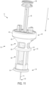
- a medical injector 10 includes a needle assembly 12 having a needle 14, an injector housing 16, a barrel 18 having a reservoir 20 for medicament sealed by a septum 22, a stopper 24, a plunger rod 26 having a flange 68, a spring 28, a first cap 30, and a second cap or a cap remover 32.
- the medical injector 10 includes a distal end 34 and a proximal end 36.
- the reservoir 20 of the barrel 18 is encased within the injector housing 16.
- the reservoir 20 may be defined by the injector housing 16.
- the reservoir 20 may be defined by a separate component contained within the injector housing 16, e.g., a cartridge or barrel.
- the needle assembly 12 includes a needle 14 and a hub 38.
- the needle 14 includes a distal end 50, formed for insertion into a patient, and a proximal end 52.
- the medical injector 10 of the present disclosure may be of various forms, including being a syringe, self-injector, auto-injector, or pen injector.
- the medical injector 10 is well-suited for administering at least one fixed dose.
- the medical injector 10 is well-suited for administering a series of fixed doses.
- the medical injector 10 may be configured in any way known to be compatible with the plunger rod 26.
- the medical injector 10 may include a reservoir 20 for accommodating an injectable medicament, which may be a drug cartridge or formed directly in the medical injector 10.
- the reservoir 20 may have one or more stoppers 24 associated therewith.
- the injector housing 16 of the medical injector 10 includes an upper guard 40, a lower guard 42, and a base 44.
- the upper guard 40 includes a first flange 46 and a first tapered wall 48.
- the upper guard 40 provides a gripping component that includes surfaces for accommodating a user's fingers, such as finger grip indentations or similar structure.
- the upper guard 40 provides ergonomically shaped surfaces that substantially conform to a user's fingertips to aid the user in manipulating the medical injector 10 and using the medical injector 10 in a medical procedure, and may provide multiple finger grip positions for the user.
- the upper guard 40 allows a user to handle and/or grip the medical injector 10 in a variety of different ways.
- the lower guard 42 includes a second flange 60 and a second tapered wall 62.
- the lower guard 42 provides a second gripping component that includes surfaces for accommodating a user's fingers, such as finger grip indentations or similar structure.
- the lower guard 42 provides a user with vertical stability in hand, precisely during needle insertion with the medical injector 10.
- the base 44 includes a flange 64 that contacts the skin of a user during use of the medical injector 10.
- the base 44 provides a stability component that stabilizes the medical injector 10 on a user's skin during use of the medical injector 10.
- the base 44 also hides the spring 28.
- the injector housing 16, the upper guard 40, the lower guard 42, and the base 44 are configured to provide viewing windows 66.
- the viewing windows 66 allow a user to see the barrel 18 that includes the medicament.
- a first cap 30 shields and covers the distal end 50 of the needle 14.
- the second cap or cap remover 32 shields and covers the distal end 50 of the needle 14 and the first cap 30.
- the second cap 32 may be the only cap that shields and covers the distal end 50 of the needle 14.
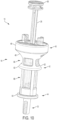
- the second cap or cap remover 32 includes a body 100 having a distal end 101, a proximal end 102, a cylindrical portion 104 adjacent the proximal end 102, and a hemispherical portion 106 adjacent the distal end 101.
- the hemispherical portion 106 includes an outer wall 110, an inner wall 112, a distal flange 114, a first cavity 116, and a distal wall 118.
- the outer wall 110 of the hemispherical portion 106 provides a gripping component that includes surfaces for accommodating a user's fingers, such as finger grip indentations or similar structure.
- the outer wall 110 of the hemispherical portion 106 provides ergonomically shaped surfaces that substantially conform to a user's fingertips to aid the user in handling and grasping the second cap 32.
- the outer wall 110 of the hemispherical portion 106 includes finger grip indentations 120 for providing a gripping component for accommodating a user's fingers.
- the finger grip indentations 120 improve the grip between the second cap 32 and the user's fingertips.
- the finger grip indentations 120 are formed as a plurality of ribs 122 and troughs 124 extending along the periphery of the outer wall 110 of the hemispherical portion 106.
- the finger grip indentations 120 are formed as a plurality of alternating ribs 122 and troughs 124 extending circumferentially about the periphery of the outer wall 110 of the hemispherical portion 106.
- the hemispherical portion 106 may terminate at a distal flange 119 having a substantially flat distal distally directed surface.
- the alternating ribs 122 and troughs 124 are integrally formed with the second cap 32 and provide a visual and tactile cue to the user to instruct the user where to place his or her fingertips.
- the shape of the second cap 32 is designed to help disabled people more easily and more conveniently handle the second cap 32 and/or the medical injector 10.
- the cylindrical portion 104 includes an outer cylindrical portion 130, an inner cylindrical portion 132, an outer wall 134, and inner wall 136, defining a second cavity 138.
- the cylindrical portion 104 provides a secure attachment of the second cap 32 to the distal end 34 of the medical injector 10 as shown in Fig. 9 .
- the outer cylindrical portion 130 extends proximally from the hemispherical portion 106.
- the inner cylindrical portion 132 extends into a portion of the hemispherical portion 106.
- the outer cylindrical portion 130 may include a metallic ring integrated therewith.
- the inner wall 136 of the cylindrical portion 104 defines a second cavity 138 in the proximal end 102 of the cylindrical portion 104.
- the outer wall 134 of the inner cylindrical portion 132 and the inner wall 112 of the hemispherical portion 106 define the first cavity 116 therebetween.
- the second cavity 138 is sized and shaped to receive at least a portion of the first cap 30 therein.
- a protrusion 115 may extend inwardly from the interior wall 136 toward a longitudinal axis of the body 100.
- the protrusion 115 is an annular ring.
- a plurality of circumferentially spaced protrusions 115 extend inwardly from the interior wall 136 toward a longitudinal axis of the body 100.
- the protrusion 115 may include a tapered proximal surface angled from the interior wall 136 inwardly toward the longitudinal axis of the body 100 and downwardly toward the distal end 101 of the body 100 for aiding the second cap 32 in sliding over the first cap 30.
- the second cap 32 is engaged with the first cap 30 such that removal of the second cap 32 simultaneously removes the first cap 30 from the distal end 50 of the needle 14.
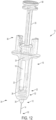
- the second cap or the cap remover 32 is removed from the medical injector 10 by applying a distally directed force F to the second cap or cap remover 32, as shown in Fig. 9 .
- the hemispherical portion 106 of the second cap 32 provides the above-described gripping component. In one embodiment, the hemispherical portion 106 of the second cap 32 provides ergonomically shaped surfaces that improve the grip between the second cap 32 and the user's fingertips to aid the user in removing the second cap 32 from the distal end 50 of the needle 14 and/or to aid the user in simultaneously removing the second cap 32 and the first cap 30 from the distal end 50 of the needle 14.
- the second cap 32 allows a user to handle the second cap 32 without finger flexion.
- the hemispherical portion 106 of the second cap 32 provides a gripping component that allows a user to better handle the second cap 32 and/or the medical injector 10.
- the second cap 32 is used to easily remove the second cap 32 and the first cap 30 from the distal end 50 of the needle 14 simultaneously. Referring to Fig. 11 , with the caps 30, 32 removed, the distal end 50 of the needle 14 is exposed and ready to be positioned adjacent a desired portion of the skin of a user.
- the second cap 32 may be the only cap that shields and covers the distal end 50 of the needle 14.
- the flange 68 of the plunger rod 26 and a portion of the injector housing 16 can be grasped, e.g., with the user's thumb on the flange 68 of the plunger rod 26 and with the user's fingers extending around the first flange 46 of the upper guard 40 of injector housing 16.
- the medical injector 10 can be grasped by a user in a well-known and well-recognized manner similar to the operation of a conventional hypodermic syringe.
- the user effects a squeezing movement between the thumb on the flange 68 of the plunger rod 26 and four fingers grasping the first flange 46 of the upper guard 40, thereby causing the plunger rod 26 to move in a direction generally along arrow A ( Fig. 11 ).
- Movement of the plunger rod 26 in the direction generally along arrow A actuates movement of the stopper 24 in the direction generally along arrow A toward the distal end 34 of the medical injector 10. In this manner, movement of the stopper 24 in the direction generally along arrow A forces the medicament fluid contained within the reservoir 20 of the barrel 18 to be forced out the distal end 50 of the needle 14 and into the user and/or patient.
- the needle 14 can be removed from the skin of the patient.
- the medical injector 10 may include an automatic retraction mechanism for moving the needle 14 into the injector housing 16 for safe shielding of the needle 14 after use.
- the spring 28 may be used as part of the automatic retraction mechanism.
- All of the components of the medical injector 10 may be constructed of any known material, and are desirably constructed of medical-grade polymers.
Landscapes
- Health & Medical Sciences (AREA)
- Engineering & Computer Science (AREA)
- Hematology (AREA)
- Anesthesiology (AREA)
- Biomedical Technology (AREA)
- Heart & Thoracic Surgery (AREA)
- Vascular Medicine (AREA)
- Life Sciences & Earth Sciences (AREA)
- Animal Behavior & Ethology (AREA)
- General Health & Medical Sciences (AREA)
- Public Health (AREA)
- Veterinary Medicine (AREA)
- Environmental & Geological Engineering (AREA)
- Infusion, Injection, And Reservoir Apparatuses (AREA)
Claims (10)
- Kappenentferner (32) für einen medizinischen Injektor (10), wobei der Kappenentferner (32) aufweist:einen zylindrischen Bereich (104);und ein halbkugelförmiges Element (106) mit einer Griffkomponente;wobei der zylindrische Bereich (104) eine Innenwand (136) aufweist, die sich von einem proximalen Ende (102) zu einem distalen Ende erstreckt, und die Innenwand (136) einen Hohlraum (138) definiert;das halbkugelförmige Element (106) ein proximales Ende aufweist, das mit dem zylindrischen Ende verbunden ist und sich zu einem distalen Ende (101) erstreckt,der Kappenentferner (32) zum Positionieren an dem medizinischen Injektor (10) geeignet ist, wobei das distale Ende des zylindrischen Bereichs (104) weiter von einem Injektionsgehäuse (16) des medizinischen Gehäuses beabstandet ist als das proximale Ende (102) des zylindrischen Bereichs (104) und das distale Ende (101) des halbkugelförmigen Elements (106) weiter von dem Injektorgehäuse (16) beabstandet ist, las das proximale Ende des halbkugelförmigen Bereichs, undder Hohlraum (138) zum zumindest teilweisen Aufnehmen einer an dem medizinischen Injektor angeordneten Kappe (30) bemessen und ausgebildet ist, undder Kappenentferner (32), bei in dem Hohlraum (138) aufgenommener Kappe (30), die Kappe (20) von dem medizinischen Injektor (10) entfernen kann,wobeidas proximale Ende des halbkugelförmigen Elements (106) einen ersten Durchmesser und das distale Ende (101) des halbkugelförmigen Elements (106) einen zweiten Durchmesser aufweist, wobei der zweite Durchmesser größer als der erste Durchmesser ist.
- Kappenentferner (32) nach Anspruch 1, bei welchem der Kappenentferner (32) mittels Reibpassung mit der Kappe (30) zusammengreift.
- Kappenentferner (32) nach Anspruch 1, ferner mit einem Vorsprung (115), der sich von der Innenwand (136) einwärts erstreckt und zum reibenden Angreifen an der Kappe (30) geeignet ist.
- Kappenentferner (32) nach Anspruch 1, bei welchem die Kappe (30) ein erstes Material aufweist, und der Kappenentferner (32) ein zweites Material aufweist, und das erste Material von dem zweiten Material verschieden ist, und wobei das zweite Material vorzugsweise härter als das erste Material ist.
- Kappenentferner (32) nach Anspruch 1, bei welchem die Griffkompnente mindestens eine Rippe (122) aufweist, die sich zumindest teilweise um das halbkugelförmige Element (106) erstreckt, wobei die Griffkomponente vorzugsweise ferner mindestens eine Vertiefung (124) aufweist, die sich der mindestens einen Rippe (112) benachbart zumindest teilweise um das halbkugelförmige Element (106) erstreckt.
- Kappenentferner (32) nach Anspruch 1, bei welchem die Griffkomponente mehrere Rippen (122) und mehrere Vertiefungen (124) aufweist, die sich umfangsmäßig um das halbkreisförmige Element (106) erstrecken, und wobei die mehreren Rippen (122) und die mehreren Vertiefungen (124) von dem proximalen Ende zum distalen Ende (101) des halbkugelförmigen Elements (106) abwechseln.
- Kappenentferner (32) nach Anspruch 1, bei welchem das halbkugelförmige Element (106) ferner einen Flansch (119) mit einer im Wesentlichen distal gerichteten Fläche aufweist.
- Medizinischer Injektor (10) mit:einem Injektorgehäuse (10), das ein Reservoir (20) definiert;einer Kolbenstange (26);einem Stopfen (24), der mit einem Bereich der Kolbenstange (26) zusammengreift und gleitend verschiebbar in dem Reservoir (20) angeordnet ist, wobei der Stopfen (24) in Bezug auf einen Innenraum des Injektorgehäuses (16) so bemessen ist, dass er einen dichtenden Angriff an einer Seitenwand des Injektorgehäuses (16) bereitstellt;einer Nadel (14) mit einem scharfen ersten Ende (50) und einem zweiten Ende (52) in Verbindung mit dem Reservoir (20);einer Kappe (30), welche das scharfe erste Ende (50) der Nadel (14) bedeckt; undeinem Kappenentferner (32) nach einem der Ansprüche 1-7,wobei der Kappenentferner (32) derart mit der Kappe (30) zusammengreift, dass ein Entfernen der zweiten Kappe (32) gleichzeitig die Kappe (30) von dem ersten Ende (50) der Nadel (14) entfernt.
- Medizinischer Injektor (10) nach Anspruch 8, ferner mit einem flüssigen Medikament, das in dem Reservoir (20) angeordnet ist.
- Medizinscher Injektor (10) nach Anspruch 8, bei welchem die erste Kappe (30) eine elastomere Hülse aufweist, die zumindest über dem scharfen ersten Ende (50) der Nadel (14) angeordnet ist.
Applications Claiming Priority (2)
| Application Number | Priority Date | Filing Date | Title |
|---|---|---|---|
| US201562264518P | 2015-12-08 | 2015-12-08 | |
| PCT/IB2016/057446 WO2017098437A1 (en) | 2015-12-08 | 2016-12-08 | Cap with hemisphere portion for medical injector |
Publications (3)
| Publication Number | Publication Date |
|---|---|
| EP3386572A1 EP3386572A1 (de) | 2018-10-17 |
| EP3386572B1 true EP3386572B1 (de) | 2024-12-04 |
| EP3386572C0 EP3386572C0 (de) | 2024-12-04 |
Family
ID=57570575
Family Applications (1)
| Application Number | Title | Priority Date | Filing Date |
|---|---|---|---|
| EP16813248.8A Active EP3386572B1 (de) | 2015-12-08 | 2016-12-08 | Kappe mit halbkugelteil für medizinischen injektor |
Country Status (6)
| Country | Link |
|---|---|
| US (2) | US10300216B2 (de) |
| EP (1) | EP3386572B1 (de) |
| JP (2) | JP6600095B2 (de) |
| KR (1) | KR102209807B1 (de) |
| CN (1) | CN108290008B (de) |
| WO (1) | WO2017098437A1 (de) |
Families Citing this family (8)
| Publication number | Priority date | Publication date | Assignee | Title |
|---|---|---|---|---|
| USD810282S1 (en) * | 2015-10-19 | 2018-02-13 | Carebay Europe Ltd | Medical injector |
| US10300216B2 (en) * | 2015-12-08 | 2019-05-28 | Becton Dickinson France S.A.S. | Cap with hemisphere portion for medical injector |
| GB2563029B (en) * | 2017-05-30 | 2022-06-08 | Janssen Pharmaceuticals Inc | Grip accessory for a manual injection device |
| GB2563027B (en) | 2017-05-30 | 2022-04-06 | Janssen Pharmaceuticals Inc | Grip accessory for a manual injection device |
| CN110384841B (zh) * | 2018-04-18 | 2023-03-31 | 恩贝克塔公司 | 笔式针组件装置 |
| ES2959943T3 (es) * | 2018-10-05 | 2024-02-29 | Becton Dickinson France | Extractor de tapa de cobertura con compresión de la junta de estanqueidad |
| GB2580133B (en) * | 2018-12-21 | 2023-04-12 | Janssen Pharmaceuticals Inc | Accessory including a slot for a flange of an injection device |
| GB2580142B (en) | 2018-12-21 | 2023-04-12 | Janssen Pharmaceuticals Inc | Accessory for an injection including a pivotable cover |
Family Cites Families (83)
| Publication number | Priority date | Publication date | Assignee | Title |
|---|---|---|---|---|
| US2131687A (en) * | 1937-07-01 | 1938-09-27 | Kastar Specialty Mfg Co Inc | Suction handle |
| US4365626A (en) | 1979-10-25 | 1982-12-28 | House Hugh A | Universal syringe |
| CA1257163A (en) | 1985-09-23 | 1989-07-11 | Bruce Rosenberg | Tamper evident injection syringe |
| US4636201A (en) * | 1985-11-01 | 1987-01-13 | American Hospital Supply Corporation | Hypodermic syringe having a protective sheath cover |
| US4872721A (en) * | 1988-08-10 | 1989-10-10 | Sniadach James R | Automotive sunscreen |
| US4898588A (en) * | 1988-10-17 | 1990-02-06 | Roberts Christopher W | Hypodermic syringe splatter shield |
| US4986817A (en) * | 1988-11-22 | 1991-01-22 | International Development Systems, Inc. | Hypodermic syringe sheath holder and needle guide |
| US4929232A (en) | 1989-03-30 | 1990-05-29 | Becton, Dickinson And Company | Syringe having tamper evidence features |
| US4982842A (en) * | 1990-06-04 | 1991-01-08 | Concord/Portex | Safety needle container |
| US5183469A (en) * | 1991-05-10 | 1993-02-02 | Becton, Dickinson And Company | Device for the removal and replacement of a needle shield |
| USD337157S (en) | 1991-05-20 | 1993-07-06 | Ortiz German L | Replacement valve for endotracheal tube inflation cuff |
| USD375788S (en) | 1995-06-19 | 1996-11-19 | Ciba Corning Diagnostics Corp. | Ampule adapter |
| USD380262S (en) | 1995-06-26 | 1997-06-24 | Minimed Inc. | Quick disconnect coupling |
| US5647849A (en) | 1995-09-27 | 1997-07-15 | Becton, Dickinson And Company | Self-contained safety syringe |
| CA2229522A1 (en) | 1998-04-15 | 1999-10-15 | Thomas Randall Inkpen | Needle aid |
| USD427308S (en) | 1999-01-22 | 2000-06-27 | Medimop Medical Projects Ltd. | Vial adapter |
| US6582397B2 (en) | 2001-06-19 | 2003-06-24 | Portex, Inc. | Needle safety device with antiremoval protection |
| EP1453561B1 (de) | 2001-12-13 | 2016-08-31 | Becton Dickinson and Company | Vorrichtung zur entfernung eines nadel-verschlusssystems |
| USD473646S1 (en) | 2001-12-21 | 2003-04-22 | Microsurgical Technology, Inc. | Irrigation/aspiration instrument connector |
| GB0201470D0 (en) | 2002-01-23 | 2002-03-13 | Kapitex Healthcare Ltd | Tracheostoma valve |
| US6997913B2 (en) | 2002-06-07 | 2006-02-14 | Becton, Dickinson And Company | Needle safety device |
| USD486225S1 (en) | 2002-11-22 | 2004-02-03 | Pbm Plastics, Inc. | Breast pump adapter |
| USD483487S1 (en) | 2002-12-19 | 2003-12-09 | Becton Dickinson And Company | Stopcock device |
| CN1816368A (zh) * | 2003-03-06 | 2006-08-09 | 埃尔布兰手术用品有限公司 | 吹入器和使用方法 |
| USD492774S1 (en) | 2003-03-10 | 2004-07-06 | Becton Dickinson And Company | Introducer needle assembly |
| AU153839S (en) | 2003-03-13 | 2003-11-25 | Bayer Schering Pharma Oy | Implant inserter |
| US7524308B2 (en) | 2003-04-16 | 2009-04-28 | Becton, Dickinson And Company | Safety shielding needle assembly with passive shielding |
| USD505200S1 (en) | 2003-09-09 | 2005-05-17 | Smiths Medical Asd, Inc. | Fixed needle assembly |
| IL157981A (en) | 2003-09-17 | 2014-01-30 | Elcam Medical Agricultural Cooperative Ass Ltd | Auto injector |
| FR2899482A1 (fr) | 2006-04-11 | 2007-10-12 | Becton Dickinson France Soc Pa | Dispositif d'injection automatique |
| US7871397B2 (en) * | 2006-12-26 | 2011-01-18 | Stat Medical Devices, Inc. | Pen needle tip |
| US20080228147A1 (en) * | 2007-03-15 | 2008-09-18 | Bristol-Myers Squibb Company | Injector for use with pre-filled syringes and method of assembly |
| USD571006S1 (en) | 2007-03-23 | 2008-06-10 | Smiths Medical Asd, Inc. | Oval tapering blunt cannula proximal portion |
| USD629510S1 (en) | 2008-03-14 | 2010-12-21 | Becton, Dickinson And Company | Cap |
| USD636077S1 (en) | 2008-08-27 | 2011-04-12 | Deka Products Limited Partnership | Fluidic connector |
| USD607558S1 (en) | 2008-09-19 | 2010-01-05 | Becton Dickinson France S.A.S. | Medicine injector |
| GB2465390A (en) * | 2008-11-17 | 2010-05-19 | Owen Mumford Ltd | Syringe needle cover remover |
| CN102341139B (zh) | 2009-03-03 | 2014-06-04 | 诺沃—诺迪斯克有限公司 | 盖帽锁 |
| WO2010136076A1 (de) * | 2009-05-29 | 2010-12-02 | Tecpharma Licensing Ag | Injektionsvorrichtung mit einer einrichtung zum trennen einer nadelschutzkappe von einem produktbehältnis |
| JP2012529322A (ja) * | 2009-06-12 | 2012-11-22 | ノボ・ノルデイスク・エー/エス | 針アセンブリのためのキャップ機能を有する薬剤送達装置 |
| USD742508S1 (en) | 2013-07-12 | 2015-11-03 | Resmed Limited | Air delivery tube with cuff |
| USD633199S1 (en) | 2009-10-05 | 2011-02-22 | Pyng Medical Corp. | Insertion tool for bone portals |
| NZ705415A (en) | 2009-10-16 | 2016-01-29 | Janssen Biotech Inc | Palm activated drug delivery device |
| USD637713S1 (en) | 2009-11-20 | 2011-05-10 | Carmel Pharma Ab | Medical device adaptor |
| JP6105288B2 (ja) * | 2009-12-04 | 2017-03-29 | ベクトン・ディキンソン・アンド・カンパニーBecton, Dickinson And Company | 薬物送達装置のペンニードル取外し装置 |
| USD655000S1 (en) | 2010-01-13 | 2012-02-28 | Mirigian Aram J | Syringe holder |
| USD655017S1 (en) | 2010-06-17 | 2012-02-28 | Yukon Medical, Llc | Shroud |
| USD642261S1 (en) | 2010-09-15 | 2011-07-26 | Abbott Medical Optics Inc. | Securing device for cannula attachment to syringe body |
| USD679008S1 (en) | 2011-01-07 | 2013-03-26 | Remot Medical Innovation, LLC | Endotracheal tube adaptor |
| CA3145238A1 (en) * | 2011-04-20 | 2012-10-26 | Amgen Inc. | Autoinjector apparatus |
| USD681230S1 (en) | 2011-09-08 | 2013-04-30 | Yukon Medical, Llc | Shroud |
| US9119919B2 (en) | 2011-09-30 | 2015-09-01 | Becton Dickinson France, S.A.S. | Syringe having a squeeze-fit plunger rod |
| US9233212B2 (en) * | 2011-10-17 | 2016-01-12 | Shl Group Ab | Device for removing delivery member shields |
| USD702835S1 (en) | 2012-01-04 | 2014-04-15 | Anteis Sa | Needle retaining device |
| FR2999436B1 (fr) * | 2012-12-14 | 2016-02-05 | Transformation Des Elastomeres A Usages Medicaux Et Ind Soc D | Systeme de protection d'aiguille d'un dispositif d'injection. |
| USD718439S1 (en) | 2012-12-17 | 2014-11-25 | B. Braun Melsungen Ag | Actuator assembly for a valved catheter |
| USD738494S1 (en) | 2013-03-05 | 2015-09-08 | Ikashmore Pty Ltd | Blood collection safety device |
| US10022301B2 (en) * | 2013-03-15 | 2018-07-17 | Becton Dickinson and Company Ltd. | Connection system for medical device components |
| EA039027B1 (ru) | 2013-03-15 | 2021-11-23 | Янссен Байотек, Инк. | Устройство для доставки лекарственных средств, приводимое в действие ладонью |
| KR20150136102A (ko) | 2013-03-25 | 2015-12-04 | 케어베이 유럽 리미티드 | 약물 전달 장치용 전방 캡 |
| USD757258S1 (en) | 2013-04-11 | 2016-05-24 | Aesculap Ag | Container seal |
| USD709753S1 (en) | 2013-05-23 | 2014-07-29 | Industrie Borla, S.P.A. | Locking cannula |
| US20160193428A1 (en) | 2013-08-02 | 2016-07-07 | Union Medico Aps | Injection device |
| TW201519886A (zh) * | 2013-08-29 | 2015-06-01 | Sanofi Sa | 用於藥物容器的帽蓋 |
| USD750258S1 (en) | 2013-09-06 | 2016-02-23 | Asalus Medical Instruments Ltd | Medical instrument |
| USD768850S1 (en) | 2013-10-29 | 2016-10-11 | Htl-Strefa Spolka Akcyjna | Needle shield |
| USD750239S1 (en) | 2013-10-31 | 2016-02-23 | Nordson Corporation | Adapter collar for a syringe |
| CN105722539B (zh) | 2013-11-13 | 2021-01-15 | 豪夫迈·罗氏有限公司 | 辅助式手动注射装置和方法 |
| NZ719831A (en) * | 2013-12-06 | 2019-11-29 | Genentech Inc | Apparatus and methods for low-volume medicament delivery |
| WO2015105511A1 (en) | 2014-01-13 | 2015-07-16 | West Pharmaceutical Services, Inc. | Rigid needle shield with pivotable arms |
| USD757935S1 (en) | 2014-02-06 | 2016-05-31 | Karl Storz Endoscopy-America, Inc. | Rotation wheel extension |
| HK1226341A1 (zh) * | 2014-02-11 | 2017-09-29 | Eli Lilly And Company | 抓取刚性针罩的盖组件 |
| USD760891S1 (en) | 2014-02-12 | 2016-07-05 | Abbvie Inc. | Injection tool |
| USD755966S1 (en) | 2014-03-11 | 2016-05-10 | Prabhat Kumar Ahluwalia | Medical device |
| USD755967S1 (en) | 2014-03-11 | 2016-05-10 | Prabhat Kumar Ahluwalia | Medical device |
| USD750779S1 (en) | 2014-03-11 | 2016-03-01 | Prabhat Kumar Ahluwalia | Medical device |
| EP2923716A1 (de) | 2014-03-28 | 2015-09-30 | Sanofi-Aventis Deutschland GmbH | Kappe mit Hüllenentfernungsmechanismus |
| EP2923714A1 (de) * | 2014-03-28 | 2015-09-30 | Sanofi-Aventis Deutschland GmbH | Durch hautkontakt ausgelöste Autoinjektor |
| USD751192S1 (en) | 2014-05-14 | 2016-03-08 | Health Line International Corp. | Medical device |
| USD768851S1 (en) | 2014-06-30 | 2016-10-11 | Htl-Strefa Spolka Akcyjna | Safety needle device |
| USD765241S1 (en) | 2014-09-15 | 2016-08-30 | Owen Mumford Ltd. | Syringe |
| WO2017086607A1 (ko) * | 2015-11-16 | 2017-05-26 | (주)유니테코 | 주사기 안전 캡 조립체 |
| US10300216B2 (en) * | 2015-12-08 | 2019-05-28 | Becton Dickinson France S.A.S. | Cap with hemisphere portion for medical injector |
-
2016
- 2016-12-08 US US15/372,630 patent/US10300216B2/en active Active
- 2016-12-08 KR KR1020187019489A patent/KR102209807B1/ko active Active
- 2016-12-08 EP EP16813248.8A patent/EP3386572B1/de active Active
- 2016-12-08 JP JP2018530062A patent/JP6600095B2/ja active Active
- 2016-12-08 CN CN201680068580.5A patent/CN108290008B/zh active Active
- 2016-12-08 WO PCT/IB2016/057446 patent/WO2017098437A1/en not_active Ceased
-
2019
- 2019-04-09 US US16/378,920 patent/US11154662B2/en active Active
- 2019-10-03 JP JP2019183262A patent/JP7001649B2/ja active Active
Also Published As
| Publication number | Publication date |
|---|---|
| US20190231988A1 (en) | 2019-08-01 |
| US11154662B2 (en) | 2021-10-26 |
| JP7001649B2 (ja) | 2022-01-19 |
| US10300216B2 (en) | 2019-05-28 |
| KR102209807B1 (ko) | 2021-01-29 |
| JP2018536501A (ja) | 2018-12-13 |
| JP6600095B2 (ja) | 2019-10-30 |
| CN108290008B (zh) | 2024-03-08 |
| WO2017098437A1 (en) | 2017-06-15 |
| EP3386572A1 (de) | 2018-10-17 |
| JP2020018879A (ja) | 2020-02-06 |
| CN108290008A (zh) | 2018-07-17 |
| US20170157334A1 (en) | 2017-06-08 |
| EP3386572C0 (de) | 2024-12-04 |
| KR20180093023A (ko) | 2018-08-20 |
Similar Documents
| Publication | Publication Date | Title |
|---|---|---|
| US12161850B2 (en) | Cap for medical injector | |
| US11154662B2 (en) | Cap with hemisphere portion for medical injector | |
| JP2020099832A (ja) | 医療インジェクタおよびキャップリムーバ | |
| US10737036B2 (en) | Housing and cap for medical injector |
Legal Events
| Date | Code | Title | Description |
|---|---|---|---|
| STAA | Information on the status of an ep patent application or granted ep patent |
Free format text: STATUS: UNKNOWN |
|
| STAA | Information on the status of an ep patent application or granted ep patent |
Free format text: STATUS: THE INTERNATIONAL PUBLICATION HAS BEEN MADE |
|
| PUAI | Public reference made under article 153(3) epc to a published international application that has entered the european phase |
Free format text: ORIGINAL CODE: 0009012 |
|
| STAA | Information on the status of an ep patent application or granted ep patent |
Free format text: STATUS: REQUEST FOR EXAMINATION WAS MADE |
|
| 17P | Request for examination filed |
Effective date: 20180704 |
|
| AK | Designated contracting states |
Kind code of ref document: A1 Designated state(s): AL AT BE BG CH CY CZ DE DK EE ES FI FR GB GR HR HU IE IS IT LI LT LU LV MC MK MT NL NO PL PT RO RS SE SI SK SM TR |
|
| AX | Request for extension of the european patent |
Extension state: BA ME |
|
| DAV | Request for validation of the european patent (deleted) | ||
| DAX | Request for extension of the european patent (deleted) | ||
| STAA | Information on the status of an ep patent application or granted ep patent |
Free format text: STATUS: EXAMINATION IS IN PROGRESS |
|
| 17Q | First examination report despatched |
Effective date: 20220614 |
|
| GRAP | Despatch of communication of intention to grant a patent |
Free format text: ORIGINAL CODE: EPIDOSNIGR1 |
|
| STAA | Information on the status of an ep patent application or granted ep patent |
Free format text: STATUS: GRANT OF PATENT IS INTENDED |
|
| INTG | Intention to grant announced |
Effective date: 20240812 |
|
| GRAS | Grant fee paid |
Free format text: ORIGINAL CODE: EPIDOSNIGR3 |
|
| GRAA | (expected) grant |
Free format text: ORIGINAL CODE: 0009210 |
|
| STAA | Information on the status of an ep patent application or granted ep patent |
Free format text: STATUS: THE PATENT HAS BEEN GRANTED |
|
| AK | Designated contracting states |
Kind code of ref document: B1 Designated state(s): AL AT BE BG CH CY CZ DE DK EE ES FI FR GB GR HR HU IE IS IT LI LT LU LV MC MK MT NL NO PL PT RO RS SE SI SK SM TR |
|
| REG | Reference to a national code |
Ref country code: GB Ref legal event code: FG4D |
|
| REG | Reference to a national code |
Ref country code: CH Ref legal event code: EP |
|
| REG | Reference to a national code |
Ref country code: DE Ref legal event code: R096 Ref document number: 602016090520 Country of ref document: DE |
|
| REG | Reference to a national code |
Ref country code: IE Ref legal event code: FG4D |
|
| U01 | Request for unitary effect filed |
Effective date: 20250103 |
|
| U07 | Unitary effect registered |
Designated state(s): AT BE BG DE DK EE FI FR IT LT LU LV MT NL PT RO SE SI Effective date: 20250115 |
|
| U20 | Renewal fee for the european patent with unitary effect paid |
Year of fee payment: 9 Effective date: 20250228 |
|
| PG25 | Lapsed in a contracting state [announced via postgrant information from national office to epo] |
Ref country code: HR Free format text: LAPSE BECAUSE OF FAILURE TO SUBMIT A TRANSLATION OF THE DESCRIPTION OR TO PAY THE FEE WITHIN THE PRESCRIBED TIME-LIMIT Effective date: 20241204 |
|
| PG25 | Lapsed in a contracting state [announced via postgrant information from national office to epo] |
Ref country code: ES Free format text: LAPSE BECAUSE OF FAILURE TO SUBMIT A TRANSLATION OF THE DESCRIPTION OR TO PAY THE FEE WITHIN THE PRESCRIBED TIME-LIMIT Effective date: 20241204 |
|
| PG25 | Lapsed in a contracting state [announced via postgrant information from national office to epo] |
Ref country code: NO Free format text: LAPSE BECAUSE OF FAILURE TO SUBMIT A TRANSLATION OF THE DESCRIPTION OR TO PAY THE FEE WITHIN THE PRESCRIBED TIME-LIMIT Effective date: 20250304 |
|
| PG25 | Lapsed in a contracting state [announced via postgrant information from national office to epo] |
Ref country code: GR Free format text: LAPSE BECAUSE OF FAILURE TO SUBMIT A TRANSLATION OF THE DESCRIPTION OR TO PAY THE FEE WITHIN THE PRESCRIBED TIME-LIMIT Effective date: 20250305 |
|
| PGFP | Annual fee paid to national office [announced via postgrant information from national office to epo] |
Ref country code: GB Payment date: 20250123 Year of fee payment: 9 |
|
| PG25 | Lapsed in a contracting state [announced via postgrant information from national office to epo] |
Ref country code: RS Free format text: LAPSE BECAUSE OF FAILURE TO SUBMIT A TRANSLATION OF THE DESCRIPTION OR TO PAY THE FEE WITHIN THE PRESCRIBED TIME-LIMIT Effective date: 20250304 |
|
| PG25 | Lapsed in a contracting state [announced via postgrant information from national office to epo] |
Ref country code: SM Free format text: LAPSE BECAUSE OF FAILURE TO SUBMIT A TRANSLATION OF THE DESCRIPTION OR TO PAY THE FEE WITHIN THE PRESCRIBED TIME-LIMIT Effective date: 20241204 |
|
| PG25 | Lapsed in a contracting state [announced via postgrant information from national office to epo] |
Ref country code: PL Free format text: LAPSE BECAUSE OF FAILURE TO SUBMIT A TRANSLATION OF THE DESCRIPTION OR TO PAY THE FEE WITHIN THE PRESCRIBED TIME-LIMIT Effective date: 20241204 |
|
| PG25 | Lapsed in a contracting state [announced via postgrant information from national office to epo] |
Ref country code: IS Free format text: LAPSE BECAUSE OF FAILURE TO SUBMIT A TRANSLATION OF THE DESCRIPTION OR TO PAY THE FEE WITHIN THE PRESCRIBED TIME-LIMIT Effective date: 20250404 |
|
| PG25 | Lapsed in a contracting state [announced via postgrant information from national office to epo] |
Ref country code: SK Free format text: LAPSE BECAUSE OF FAILURE TO SUBMIT A TRANSLATION OF THE DESCRIPTION OR TO PAY THE FEE WITHIN THE PRESCRIBED TIME-LIMIT Effective date: 20241204 |
|
| PG25 | Lapsed in a contracting state [announced via postgrant information from national office to epo] |
Ref country code: CZ Free format text: LAPSE BECAUSE OF FAILURE TO SUBMIT A TRANSLATION OF THE DESCRIPTION OR TO PAY THE FEE WITHIN THE PRESCRIBED TIME-LIMIT Effective date: 20241204 |
|
| REG | Reference to a national code |
Ref country code: CH Ref legal event code: PL |
|
| PG25 | Lapsed in a contracting state [announced via postgrant information from national office to epo] |
Ref country code: MC Free format text: LAPSE BECAUSE OF FAILURE TO SUBMIT A TRANSLATION OF THE DESCRIPTION OR TO PAY THE FEE WITHIN THE PRESCRIBED TIME-LIMIT Effective date: 20241204 |
|
| PLBE | No opposition filed within time limit |
Free format text: ORIGINAL CODE: 0009261 |
|
| STAA | Information on the status of an ep patent application or granted ep patent |
Free format text: STATUS: NO OPPOSITION FILED WITHIN TIME LIMIT |
|
| PG25 | Lapsed in a contracting state [announced via postgrant information from national office to epo] |
Ref country code: CH Free format text: LAPSE BECAUSE OF NON-PAYMENT OF DUE FEES Effective date: 20241231 |
|
| PG25 | Lapsed in a contracting state [announced via postgrant information from national office to epo] |
Ref country code: IE Free format text: LAPSE BECAUSE OF NON-PAYMENT OF DUE FEES Effective date: 20241208 |
|
| 26N | No opposition filed |
Effective date: 20250905 |