EP1453561B1 - Vorrichtung zur entfernung eines nadel-verschlusssystems - Google Patents
Vorrichtung zur entfernung eines nadel-verschlusssystems Download PDFInfo
- Publication number
- EP1453561B1 EP1453561B1 EP02784781.3A EP02784781A EP1453561B1 EP 1453561 B1 EP1453561 B1 EP 1453561B1 EP 02784781 A EP02784781 A EP 02784781A EP 1453561 B1 EP1453561 B1 EP 1453561B1
- Authority
- EP
- European Patent Office
- Prior art keywords
- shield
- tubular member
- removal device
- gripping elements
- set forth
- Prior art date
- Legal status (The legal status is an assumption and is not a legal conclusion. Google has not performed a legal analysis and makes no representation as to the accuracy of the status listed.)
- Expired - Lifetime
Links
Images

Classifications
-
- A—HUMAN NECESSITIES
- A61—MEDICAL OR VETERINARY SCIENCE; HYGIENE
- A61M—DEVICES FOR INTRODUCING MEDIA INTO, OR ONTO, THE BODY; DEVICES FOR TRANSDUCING BODY MEDIA OR FOR TAKING MEDIA FROM THE BODY; DEVICES FOR PRODUCING OR ENDING SLEEP OR STUPOR
- A61M5/00—Devices for bringing media into the body in a subcutaneous, intra-vascular or intramuscular way; Accessories therefor, e.g. filling or cleaning devices, arm-rests
- A61M5/178—Syringes
- A61M5/31—Details
- A61M5/32—Needles; Details of needles pertaining to their connection with syringe or hub; Accessories for bringing the needle into, or holding the needle on, the body; Devices for protection of needles
- A61M5/3205—Apparatus for removing or disposing of used needles or syringes, e.g. containers; Means for protection against accidental injuries from used needles
- A61M5/321—Means for protection against accidental injuries by used needles
- A61M5/3213—Caps placed axially onto the needle, e.g. equipped with finger protection guards
-
- A—HUMAN NECESSITIES
- A61—MEDICAL OR VETERINARY SCIENCE; HYGIENE
- A61M—DEVICES FOR INTRODUCING MEDIA INTO, OR ONTO, THE BODY; DEVICES FOR TRANSDUCING BODY MEDIA OR FOR TAKING MEDIA FROM THE BODY; DEVICES FOR PRODUCING OR ENDING SLEEP OR STUPOR
- A61M5/00—Devices for bringing media into the body in a subcutaneous, intra-vascular or intramuscular way; Accessories therefor, e.g. filling or cleaning devices, arm-rests
- A61M5/178—Syringes
- A61M5/31—Details
- A61M5/32—Needles; Details of needles pertaining to their connection with syringe or hub; Accessories for bringing the needle into, or holding the needle on, the body; Devices for protection of needles
- A61M5/3202—Devices for protection of the needle before use, e.g. caps
-
- A—HUMAN NECESSITIES
- A61—MEDICAL OR VETERINARY SCIENCE; HYGIENE
- A61M—DEVICES FOR INTRODUCING MEDIA INTO, OR ONTO, THE BODY; DEVICES FOR TRANSDUCING BODY MEDIA OR FOR TAKING MEDIA FROM THE BODY; DEVICES FOR PRODUCING OR ENDING SLEEP OR STUPOR
- A61M5/00—Devices for bringing media into the body in a subcutaneous, intra-vascular or intramuscular way; Accessories therefor, e.g. filling or cleaning devices, arm-rests
- A61M5/178—Syringes
- A61M5/31—Details
- A61M5/32—Needles; Details of needles pertaining to their connection with syringe or hub; Accessories for bringing the needle into, or holding the needle on, the body; Devices for protection of needles
- A61M5/3205—Apparatus for removing or disposing of used needles or syringes, e.g. containers; Means for protection against accidental injuries from used needles
- A61M5/321—Means for protection against accidental injuries by used needles
- A61M5/3213—Caps placed axially onto the needle, e.g. equipped with finger protection guards
- A61M2005/3215—Tools enabling the cap placement
-
- A—HUMAN NECESSITIES
- A61—MEDICAL OR VETERINARY SCIENCE; HYGIENE
- A61M—DEVICES FOR INTRODUCING MEDIA INTO, OR ONTO, THE BODY; DEVICES FOR TRANSDUCING BODY MEDIA OR FOR TAKING MEDIA FROM THE BODY; DEVICES FOR PRODUCING OR ENDING SLEEP OR STUPOR
- A61M2205/00—General characteristics of the apparatus
- A61M2205/58—Means for facilitating use, e.g. by people with impaired vision
- A61M2205/586—Ergonomic details therefor, e.g. specific ergonomics for left or right-handed users
-
- A—HUMAN NECESSITIES
- A61—MEDICAL OR VETERINARY SCIENCE; HYGIENE
- A61M—DEVICES FOR INTRODUCING MEDIA INTO, OR ONTO, THE BODY; DEVICES FOR TRANSDUCING BODY MEDIA OR FOR TAKING MEDIA FROM THE BODY; DEVICES FOR PRODUCING OR ENDING SLEEP OR STUPOR
- A61M5/00—Devices for bringing media into the body in a subcutaneous, intra-vascular or intramuscular way; Accessories therefor, e.g. filling or cleaning devices, arm-rests
- A61M5/178—Syringes
- A61M5/31—Details
- A61M5/32—Needles; Details of needles pertaining to their connection with syringe or hub; Accessories for bringing the needle into, or holding the needle on, the body; Devices for protection of needles
- A61M5/3202—Devices for protection of the needle before use, e.g. caps
- A61M5/3204—Needle cap remover, i.e. devices to dislodge protection cover from needle or needle hub, e.g. deshielding devices
Definitions
- the subject invention relates generally to a safety device used to remove a shield from a medical assembly. More particularly, the subject invention relates to a safety device for protecting a user of the medical assembly from being pricked by a needle or other sharp device when removing a protective shield.
- a needle assembly is typically attached to a hypodermic syringe to either inject a substance into the skin of a patient or to withdraw blood from the patient.
- Other types of devices having exposed sharpened tips also staked or attached to a medical instrument are used to administer a medical procedure.
- a typical needle assembly includes a needle cannula having a sharpened tip capable of piercing the skin of a patient.
- the needle cannula or other device having a sharpened tip is commonly covered by a shield to maintain the cannula in a clean if not sterile condition and to prevent unintentional needle pricks of the user.
- a user may need to be protected from contact with an assembly having an exposed tip or connection feature that is not sharp. Contact with the tip may cause injury if the contents of the assembly are toxic, or contaminate the contents with a virus or bacteria. Therefore, an assembly with a blunt tip may also require a shield to maintain the tip in a clean or sterile condition. Prior to using the medical assembly to perform the desired medical procedure, the shield must be removed to expose the needle cannula or other sharpened or exposed tip or connection device.
- the devices disclosed in these patents are also used to reinsert the needle cannula into the shield after the desired medical procedure has been administered to the patient. This is known to be an undesirable practice because a needle cannula can become contaminated upon withdrawal from a needle shield if it comes into contact with the surface of the device that has been contaminated by a used needle assembly while reinserting the used needle assembly into the needle shield.
- a shield removal device for removing a shield from a sharp tipped medical assembly is disclosed.
- a tubular member includes a lower end and an upper end that is dimensioned to receive the shield.
- the tubular member includes an inner wall having at least one gripping element with a notch providing a flex point upon the gripping element that enables the gripping element to flex radially outwardly. By flexing radially outwardly, the tubular member receives the shield, and permanently clasps the shield allowing the sharp tipped medical assembly to be withdrawn from the shield.
- the disclosed shield removal device solves the problems associated with the prior art devices with the gripping elements that expand outwardly to receive various dimensioned shields and snap back to clasp a lip or edge of the shield. Further, the gripping elements may be configured to permanently clasp onto the shield inserted into the tubular member to prevent the inventive shield removal device from being reused.
- FIG. 4 represents a shield that covers a luer tip to which a hypodermic needle is attached after the shield is removed.
- Different types of medical devices have different dimensions and configurations. Therefore, the shields 10 used to shield the medical devices have different dimensions. These shields 10 also have different removal forces to overcome to expose the underlying needle, tip or connection to administer the desired medical procedure.
- Common to all of the shields 10 is a lip or ridge 12 disposed somewhere upon the shield that can be clasped to assist withdrawing the shield 10 from the assembly.
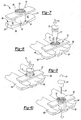
- a first embodiment of an inventive shield removal device is generally shown at 20 of Figure 5 .
- the device 20 includes a tubular member 22 having a lower end 24 and an upper end 26.
- the upper end 26 is dimensioned to receive shields 10 having a variety of dimensions and configurations.
- a base 28 includes opposing arms 30 extending radially outwardly from the tubular member 22.
- Each arm 30 may include an upper surface 32 having a generally arcuate shape providing a contoured depression surface for stabilizing the shielding device.
- the base 28 includes a generally planar lower surface 34 providing an abutment against, for example, a flat surface (not shown) enabling the device 20 to be stabilized when the upper surface 32 of the opposing arms 30 is depressed.
- the upper end 26 of the tubular member 22 includes a plurality of gripping elements 36 extending inwardly of the tubular member 22 for clasping the shield 10.
- Each gripping element 36 is separated by a gap 38 disposed longitudinally in the tubular member 22.
- Each gap 38 allows each gripping element 36 to flex radially outwardly when the tubular member 22 receives the shield 10.
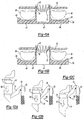
- the gripping element 36 is shown in a partial sectional view along line 6-6 of Figure 5 .
- Each gripping element 36 includes a notch 40 that provides a flex point 42 enabling the gripping element 36 additional flexible movement radially outwardly to receive the shield 10 and clasp on to the lip or ridge 14 of the shield 10.
- the notch 40 opens generally downwardly towards the lower end 24 of the tubular member 22.
- the alternative shield removal device 50 includes a tubular member 52 having a lower end 54 and an upper end 56 that is dimensioned to receive the shield 10.
- a base 58 extends outwardly from the lower end 54 of the tubular member 52 and has a generally planar lower surface 60.
- a guard 62 extends outwardly from the tubular member 52 and is spaced from the base 58 providing a gap between the base 58 and the guard 62.
- the base 58 includes opposing arms 64 each having an upper surface 66.
- Each upper surface 66 may include a generally arcuate shape providing a contoured depression surface for stabilizing the alternate needle shield device 50 by depressing downwardly upon the upper surface 66.
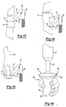
- Figures 8, 9 and 10 show the method by which the shield 10 is removed from the needle assembly 12 using the inventive alternate shield removal device 50.
- a medical provider's fingers 68 are inserted into the gap disposed between the guard 62 and the base 58.
- the medical provider depresses the device 50 downwardly onto a flat surface (not shown) in a stable manner, which is assisted by the generally arcuate upper surface 66.
- the needle assembly 12 is inserted downwardly in a direction of arrow 70 shown in Figure 8 and 9 into the upper end 56 of the tubular member 52.
- each gripping element 72 may include a sharpened tip capable of penetrating the side of the shield 10 to clasp the shield 10 for removal. Withdrawing the needle assembly 12 from the shield 10 in the direction of arrow 74 as shown in Figure 10 exposes a needle 76 or other tip or connection feature. The medical provider can now provide the desired medical procedure having safely removed the needle cannula 76 from the shield 10.
- the needle can either be reinserted into the shield 10 in the combination of the needle assembly 12 and the needle shield removal device 50 disposed of, or, preferably, the needle assembly 12 and the needle shield 10 and device 50 can be disposed of separately.
- FIG 11A shows a sectional view of the alternate needle shield removal device 50 and best represents the gripping elements 72 that extend inwardly of the tubular member 52.
- Each gripping element 72 is spaced radially around the tubular member 52.
- a notch 78 is disposed in each gripping element 72 providing a flex point 80 in the gripping element 72.
- the notch 78 opens generally downwardly towards the lower end 54 of the tubular member 52.
- the flex point 80 enables the gripping element 72 to flex radially outwardly to receive the needle shield 10 and to permanently clasp the needle shield 10 allowing the needle assembly 12 to be withdrawn from the shield 10.
- An alternate embodiment is shown in Figure 11B having an opening 61 disposed below the tubular member 52, which allows the shield 10 to be ejected from the tubular member 52. This would enable the device 50 to be reused as needed.
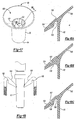
- Figures 12A through 12C show the flex action of the gripping element 72 to receive the shield 10 and to clasp permanently the ridge or lip 14 of the needle shield 10.
- Figure 12A shows the shield 10 initially being inserted into the tubular member 52 in the direction of arrow 82.
- Figure 12B shows the gripping element 72 flexing radially outwardly in the direction of arrow 84 to receive the shield 10.
- Figure 12C shows the gripping element 72 flexing inwardly in the direction of arrow 86 toward original position locking onto the ridge or lip 14 of the shield 10 permanently retaining the shield 10 in the tubular member 52.
- Figures 13 through 15 show the gripping element 72 permanently clasping differently configured shields 10 at the ridge or lip 14 by flexing inwardly toward original position in the direction of arrow 86.
- Figure 14 shows the gripping element 72 engaging a window commonly disposed within the shield 10. The window may also commonly be formed in a rigid sheath that covers a rubber or elastomeric shield.
- a further alternate embodiment of the shield removal device is generally shown at 90 in Figures 16 , 17 and 18A -C .
- a tubular member 92 includes a lower end 94 and an upper end 96 dimensioned to receive a shield 10.
- a generally conical or frustoconical member 98 includes a large diameter opening 100 and a small diameter opening 102 integrally formed with the upper end 96 of the tubular member 92.
- the tubular member 92 includes a plurality of gripping elements 104 extending inwardly of the tubular member 92.
- Each gripping element 104 includes at least one notch 106 as represented in cross sectional view shown in Figure 18A-C pointing downwardly toward said lower end 94 of said tubular member 92.
- a second notch 107 pointing generally upwardly provides additional flex to each gripping element 104 enabling the gripping element 104 to flex to permanently clasp the shield 10 as shown in Figure 18B and 18C .
- any shape that forms a flex point 108 in the gripping element 104 will suffice.
- the gripping elements 104 are spaced circumferentially around the tubular member 92.
- the embodiments of the shield removal device 20, 50, 90 of this invention may be integrally molded from any suitable polymer, including polyethylene, polypropylene, polycarbonate, etc.
- the embodiments of the shield removal device 20, 50, 90 are also relatively simple in design and therefore inexpensive.
- the device of this invention may be preassembled onto a syringe or medical cartridge to minimize and ease manipulation by a health care worker or patient.
Landscapes
- Health & Medical Sciences (AREA)
- Engineering & Computer Science (AREA)
- Hematology (AREA)
- Anesthesiology (AREA)
- Biomedical Technology (AREA)
- Heart & Thoracic Surgery (AREA)
- Vascular Medicine (AREA)
- Life Sciences & Earth Sciences (AREA)
- Animal Behavior & Ethology (AREA)
- General Health & Medical Sciences (AREA)
- Public Health (AREA)
- Veterinary Medicine (AREA)
- Environmental & Geological Engineering (AREA)
- Infusion, Injection, And Reservoir Apparatuses (AREA)
- Measurement Of The Respiration, Hearing Ability, Form, And Blood Characteristics Of Living Organisms (AREA)
Claims (10)
- Schutzteil-Abnahmevorrichtung zum Abnehmen eines Schutzteils von einer Vorrichtung, mit:einem rohrförmigen Teil (22,52,92) mit einem unteren Ende (24,54, 94) und einem oberen Ende (26,56,96), das zur Aufnahme eines Schutzteils (10) dimensioniert ist,wobei das rohrförmige Teil (22,52,92) eine Innenwand hat, die mindestens ein von ihr nach innen abstehendes Greifelement (36,72,104) aufweist, wobei das mindestens eine Greifelement (36,72,104) in der Lage ist, sich radial nach außen zu biegen, um das Schutzteil (10) aufzunehmen,
dadurch gekennzeichnet, dassdas mindestens eine Greifelement (36,72,104) ferner in der Lage ist, sich nach innen zu biegen, um mit einer Rippe oder Lippe (12) des Schutzteils (10) verriegelnd zusammenzugreifen, wenn das Schutzteil (10) in das rohrförmige Teil (22,52,92) eingeführt wird;die Schutzteil-Abnahmevorrichtung ferner aufweist:eine von dem unteren Ende (24,54,94) des rohrförmigen Teils (22,52, 92) nach außen abstehenden Basis (28,58), die eine im Wesentlichen ebene untere Fläche (34,60) aufweist, undeine Schutzabdeckung (62), die von dem rohrförmigen Teil (22,52,92) im Abstand von der Basis (28,58) nach außen absteht, wodurch ein Spalt (38) zwischen der Basis und der Schutzabdeckung gebildet wird;wobei die Basis (28,58) einander gegenüberliegende Arme (30,64) aufweist, die jeweils eine obere Fläche (32,66) mit einer im Wesentlichen gekrümmten Form haben, welche eine konturierte Vertiefungsfläche zum Stabilisieren der Schutzteil-Abnahmevorrichtung bildet. - Vorrichtung nach Anspruch 1, bei der das rohrförmige Teil (22,52,92) mehrere von dem rohrförmigen Teil (22,52,92) nach innen abstehende Greifelemente (36,72,104) zum Umfassen des Schutzteils (10) aufweist.
- Vorrichtung nach Anspruch 2, bei der jedes der Greifelemente (36,72, 104) eine Einkerbung (40,78,106) aufweist, die ein Biegen der Greifelemente (36,72,104) radial nach außen ermöglicht, um die Vorrichtung zu befähigen, Schutzteile (10) mit verschiedenen Bemessungen zu umfassen.
- Vorrichtung nach Anspruch 2, bei der jedes Greifelement (36,72,104) durch eine in dem rohrförmigen Teil (22,52,92) gelegene Einkerbung (40,78,106) unterbrochen ist, die dem Greifelement ermöglicht, sich radial nach außen zu biegen und dadurch die Vorrichtung zu befähigen, Schutzteile (10) mit verschiedenen Bemessungen zu umfassen.
- Vorrichtung nach Anspruch 1, bei der die Basis (28,58) ein Stabilisierungsteil aufweist, das an dem rohrförmigen Teil (22,52,92) radial nach außen in einer zu den einander gegenüberliegenden Armen (30,64) im Wesentlichen rechtwinkligen Orientierung absteht.
- Schutzteil-Abnahmevorrichtung zum Abnehmen eines Schutzteils von einer Vorrichtung, mit:einem rohrförmigen Teil (22,52,92) mit einem unteren Ende (24,54, 94) und einem oberen Ende (26,56,96), das zur Aufnahme eines Schutzteils (10) dimensioniert ist,wobei die Schutzteil-Abnahmevorrichtung ferner ein im Wesentlichen konisches Teil mit einer im Durchmesser großen Öffnung (100) und einer im Durchmesser kleinen Öffnung (102) aufweist, das einstückig mit dem oberen Ende (26,56,96) des rohrförmigen Teils (22,52,92) ausgebildet ist;wobei das rohrförmige Teil (52) mehrere von dem rohrförmigen Teil (52) nach innen abstehende Greifelemente (36,72,104) aufweist, wobei jedes der mehreren Greifelemente mindestens eine Einkerbung (40,78,106) aufweist, die einen Biegepunkt (42,80,108) an den Greifelementen bildet, welcher den Greifelementen ermöglicht, sich radial nach außen zu biegen, um das Schutzteil (10) aufzunehmen;
dadurch gekennzeichnet, dassdie mehreren Greifelemente (36,72,104) in der Lage sind, sich nach innen zu biegen, um mit einer Rippe oder Lippe (12) des Schutzteils (10) verriegelnd zusammenzugreifen, wenn das Schutzteil (10) in das rohrförmige Teil (22,52,92) eingeführt wird. - Schutzteil-Abnahmevorrichtung nach Anspruch 6, bei der die mehreren Greifelemente (36,72,104) mit gegenseitigem Abstand umfangsmäßig um das rohrförmige Teil (52) herum angeordnet sind.
- Schutzteil-Abnahmevorrichtung nach Anspruch 6, bei der jede Einkerbung (40,78,106) im Wesentlichen zu dem unteren Ende (24,54,94) des rohrförmigen Teils (52) hin ausmündet.
- Schutzteil-Abnahmevorrichtung nach Anspruch 6, bei der jede Einkerbung (40,78,106) im Wesentlichen zu dem oberen Ende (26,56,96) des rohrförmigen oder konischen Teils hin ausmündet.
- Schutzteil-Abnahmevorrichtung nach Anspruch 6, bei der die Greifelemente (36,72,104) zwei Einkerbungen (106,107) aufweisen, die im Wesentlichen in entgegengesetzten Richtungen ausmünden.
Priority Applications (1)
| Application Number | Priority Date | Filing Date | Title |
|---|---|---|---|
| EP13182835.2A EP2671606B1 (de) | 2001-12-13 | 2002-12-11 | Beseitigungsvorrichtung für Nadelverschlusssystem |
Applications Claiming Priority (3)
| Application Number | Priority Date | Filing Date | Title |
|---|---|---|---|
| US34132801P | 2001-12-13 | 2001-12-13 | |
| US341328P | 2001-12-13 | ||
| PCT/US2002/039607 WO2003051423A2 (en) | 2001-12-13 | 2002-12-11 | Needle closure system removal device |
Related Child Applications (2)
| Application Number | Title | Priority Date | Filing Date |
|---|---|---|---|
| EP13182835.2A Division EP2671606B1 (de) | 2001-12-13 | 2002-12-11 | Beseitigungsvorrichtung für Nadelverschlusssystem |
| EP13182835.2A Division-Into EP2671606B1 (de) | 2001-12-13 | 2002-12-11 | Beseitigungsvorrichtung für Nadelverschlusssystem |
Publications (3)
| Publication Number | Publication Date |
|---|---|
| EP1453561A2 EP1453561A2 (de) | 2004-09-08 |
| EP1453561A4 EP1453561A4 (de) | 2010-11-03 |
| EP1453561B1 true EP1453561B1 (de) | 2016-08-31 |
Family
ID=23337092
Family Applications (2)
| Application Number | Title | Priority Date | Filing Date |
|---|---|---|---|
| EP13182835.2A Expired - Lifetime EP2671606B1 (de) | 2001-12-13 | 2002-12-11 | Beseitigungsvorrichtung für Nadelverschlusssystem |
| EP02784781.3A Expired - Lifetime EP1453561B1 (de) | 2001-12-13 | 2002-12-11 | Vorrichtung zur entfernung eines nadel-verschlusssystems |
Family Applications Before (1)
| Application Number | Title | Priority Date | Filing Date |
|---|---|---|---|
| EP13182835.2A Expired - Lifetime EP2671606B1 (de) | 2001-12-13 | 2002-12-11 | Beseitigungsvorrichtung für Nadelverschlusssystem |
Country Status (5)
| Country | Link |
|---|---|
| EP (2) | EP2671606B1 (de) |
| JP (1) | JP4451661B2 (de) |
| AU (1) | AU2002346711A1 (de) |
| ES (2) | ES2575795T3 (de) |
| WO (1) | WO2003051423A2 (de) |
Cited By (1)
| Publication number | Priority date | Publication date | Assignee | Title |
|---|---|---|---|---|
| WO2021043536A1 (en) * | 2019-09-05 | 2021-03-11 | Shl Medical Ag | A delivery member shield remover assembly |
Families Citing this family (95)
| Publication number | Priority date | Publication date | Assignee | Title |
|---|---|---|---|---|
| IL114960A0 (en) | 1995-03-20 | 1995-12-08 | Medimop Medical Projects Ltd | Flow control device |
| IL161660A0 (en) | 2004-04-29 | 2004-09-27 | Medimop Medical Projects Ltd | Liquid drug delivery device |
| GB2414402B (en) | 2004-05-28 | 2009-04-22 | Cilag Ag Int | Injection device |
| GB2414775B (en) | 2004-05-28 | 2008-05-21 | Cilag Ag Int | Releasable coupling and injection device |
| GB2414400B (en) | 2004-05-28 | 2009-01-14 | Cilag Ag Int | Injection device |
| GB2425062B (en) | 2005-04-06 | 2010-07-21 | Cilag Ag Int | Injection device |
| GB2424836B (en) | 2005-04-06 | 2010-09-22 | Cilag Ag Int | Injection device (bayonet cap removal) |
| DK1919432T3 (da) | 2005-08-11 | 2012-01-30 | Medimop Medical Projects Ltd | Overføringsindretninger for flydende medikamenter til fejlsikker korrekt rasteforbindelse på medicinske ampuller |
| US20110098656A1 (en) | 2005-09-27 | 2011-04-28 | Burnell Rosie L | Auto-injection device with needle protecting cap having outer and inner sleeves |
| GB2438591B (en) | 2006-06-01 | 2011-07-13 | Cilag Gmbh Int | Injection device |
| IL182605A0 (en) | 2007-04-17 | 2007-07-24 | Medimop Medical Projects Ltd | Fluid control device with manually depressed actuator |
| WO2009038860A2 (en) | 2007-09-18 | 2009-03-26 | Medeq Llc | Medicament mixing and injection apparatus |
| IL186290A0 (en) | 2007-09-25 | 2008-01-20 | Medimop Medical Projects Ltd | Liquid drug delivery devices for use with syringe having widened distal tip |
| GB0800103D0 (en) * | 2008-01-04 | 2008-02-13 | Owen Mumford Ltd | Sheath removver device |
| BRPI0821876B8 (pt) | 2008-01-11 | 2021-06-22 | Ucb Pharma Sa | tampa de ponta e seringa |
| GB2461085B (en) | 2008-06-19 | 2012-08-29 | Cilag Gmbh Int | Injection device |
| RS59584B1 (sr) | 2008-07-18 | 2019-12-31 | Ucb Biopharma Sprl | Sistemi za davanje lekova pacijentima sa reumatoidnim artritisom |
| USD641078S1 (en) | 2008-12-29 | 2011-07-05 | Ucb Pharma, S.A. | Medical syringe with needle tip cap |
| USD641080S1 (en) | 2009-03-31 | 2011-07-05 | Medimop Medical Projects Ltd. | Medical device having syringe port with locking mechanism |
| GB2469671A (en) * | 2009-04-23 | 2010-10-27 | Owen Mumford Ltd | Syringe sheath remover |
| USD660958S1 (en) | 2009-07-20 | 2012-05-29 | Ucb Pharma, S.A. | Device for administering medication |
| USD630732S1 (en) | 2009-09-29 | 2011-01-11 | Medimop Medical Projects Ltd. | Vial adapter with female connector |
| IL201323A0 (en) | 2009-10-01 | 2010-05-31 | Medimop Medical Projects Ltd | Fluid transfer device for assembling a vial with pre-attached female connector |
| IL202069A0 (en) | 2009-11-12 | 2010-06-16 | Medimop Medical Projects Ltd | Fluid transfer device with sealing arrangement |
| IL202070A0 (en) | 2009-11-12 | 2010-06-16 | Medimop Medical Projects Ltd | Inline liquid drug medical device |
| TW201129402A (en) * | 2009-12-16 | 2011-09-01 | Star Syringe Ltd | Syringes |
| US8684994B2 (en) | 2010-02-24 | 2014-04-01 | Medimop Medical Projects Ltd. | Fluid transfer assembly with venting arrangement |
| EP2512398B1 (de) | 2010-02-24 | 2014-08-27 | Medimop Medical Projects Ltd. | Vorrichtung mit belüftetem phiolenadapter zum transport eines flüssigen arzneimittels |
| USD669980S1 (en) | 2010-10-15 | 2012-10-30 | Medimop Medical Projects Ltd. | Vented vial adapter |
| IL209290A0 (en) | 2010-11-14 | 2011-01-31 | Medimop Medical Projects Ltd | Inline liquid drug medical device having rotary flow control member |
| WO2012082818A2 (en) * | 2010-12-14 | 2012-06-21 | West Pharmaceutical Services, Inc. | Device for removing a needle shield from a syringe and method of using same |
| IL212420A0 (en) | 2011-04-17 | 2011-06-30 | Medimop Medical Projects Ltd | Liquid drug transfer assembly |
| WO2012152694A1 (en) * | 2011-05-06 | 2012-11-15 | Sanofi-Aventis Deutschland Gmbh | Reuse protection for disposable parts |
| EP2574355A1 (de) * | 2011-09-27 | 2013-04-03 | Sanofi-Aventis Deutschland GmbH | Verpackung für eine Arzneimittelverabreichungsvorrichtung |
| IL215699A0 (en) | 2011-10-11 | 2011-12-29 | Medimop Medical Projects Ltd | Liquid drug reconstitution assemblage for use with iv bag and drug vial |
| JP2014530083A (ja) * | 2011-10-17 | 2014-11-17 | エス・ホー・エル・グループ・アクチボラゲットShl Group Ab | 投与部材シールドの除去装置 |
| KR101785356B1 (ko) * | 2011-11-08 | 2017-10-16 | 폴리 메디큐어 리미티드 | 정맥 주사용 카테터 장치 |
| USD737436S1 (en) | 2012-02-13 | 2015-08-25 | Medimop Medical Projects Ltd. | Liquid drug reconstitution assembly |
| USD720451S1 (en) | 2012-02-13 | 2014-12-30 | Medimop Medical Projects Ltd. | Liquid drug transfer assembly |
| USD674088S1 (en) | 2012-02-13 | 2013-01-08 | Medimop Medical Projects Ltd. | Vial adapter |
| IL219065A0 (en) | 2012-04-05 | 2012-07-31 | Medimop Medical Projects Ltd | Fluid transfer device with manual operated cartridge release arrangement |
| JP6181647B2 (ja) * | 2012-06-05 | 2017-08-16 | テルモ株式会社 | 針支持体組立体 |
| WO2014031521A1 (en) | 2012-08-20 | 2014-02-27 | West Pharmaceutical Services, Inc. | Needle shield removal tool |
| IL221634A0 (en) | 2012-08-26 | 2012-12-31 | Medimop Medical Projects Ltd | Universal drug vial adapter |
| IL221635A0 (en) | 2012-08-26 | 2012-12-31 | Medimop Medical Projects Ltd | Drug vial mixing and transfer device for use with iv bag and drug vial |
| WO2014041529A1 (en) | 2012-09-13 | 2014-03-20 | Medimop Medical Projects Ltd | Telescopic female drug vial adapter |
| USD734868S1 (en) | 2012-11-27 | 2015-07-21 | Medimop Medical Projects Ltd. | Drug vial adapter with downwardly depending stopper |
| IL225734A0 (en) | 2013-04-14 | 2013-09-30 | Medimop Medical Projects Ltd | A ready-to-use medicine vial device including a medicine vial closure, and a medicine vial closure for it |
| EP2983745B1 (de) | 2013-05-10 | 2018-07-11 | Medimop Medical Projects Ltd | Medizinprodukte mit stechflaschen-adapter und linear trocken drogen module |
| GB2515032A (en) | 2013-06-11 | 2014-12-17 | Cilag Gmbh Int | Guide for an injection device |
| GB2515039B (en) | 2013-06-11 | 2015-05-27 | Cilag Gmbh Int | Injection Device |
| GB2515038A (en) | 2013-06-11 | 2014-12-17 | Cilag Gmbh Int | Injection device |
| GB2517896B (en) | 2013-06-11 | 2015-07-08 | Cilag Gmbh Int | Injection device |
| USD765837S1 (en) | 2013-08-07 | 2016-09-06 | Medimop Medical Projects Ltd. | Liquid transfer device with integral vial adapter |
| USD767124S1 (en) | 2013-08-07 | 2016-09-20 | Medimop Medical Projects Ltd. | Liquid transfer device with integral vial adapter |
| DE212014000169U1 (de) | 2013-08-07 | 2016-03-14 | Medimop Medical Projects Ltd. | Flüssigkeitstransfervorrichtungen zur Verwendung mit Infusionsflüssigkeitsbehältern |
| USD757933S1 (en) | 2014-09-11 | 2016-05-31 | Medimop Medical Projects Ltd. | Dual vial adapter assemblage |
| WO2016110838A1 (en) | 2015-01-05 | 2016-07-14 | Medimop Medical Projects Ltd | Dual vial adapter assemblages with quick release drug vial adapter for ensuring correct usage |
| ES2718026T3 (es) | 2015-01-16 | 2019-06-27 | Becton Dickinson France | Sistema de almacenamiento y dispensación de fármacos para recipientes precargados |
| EP3117855A1 (de) | 2015-07-15 | 2017-01-18 | Sanofi-Aventis Deutschland GmbH | Kappe und kappenbeseitigungsvorrichtung |
| WO2017009822A1 (en) | 2015-07-16 | 2017-01-19 | Medimop Medical Projects Ltd | Liquid drug transfer devices for secure telescopic snap fit on injection vials |
| USD801522S1 (en) | 2015-11-09 | 2017-10-31 | Medimop Medical Projects Ltd. | Fluid transfer assembly |
| EP3380058B1 (de) | 2015-11-25 | 2020-01-08 | West Pharma Services IL, Ltd. | Dualphiolenadapteranordnung mit arzneimittelphiolenadapter mit selbstverschliessendem zugangsventil |
| WO2017098435A1 (en) * | 2015-12-08 | 2017-06-15 | Becton Dickinson France S.A.S. | Housing and cap for medical injector |
| EP3386571B1 (de) | 2015-12-08 | 2024-04-03 | Becton Dickinson France | T-förmige kappe für medizinischen injektor |
| EP3386572A1 (de) | 2015-12-08 | 2018-10-17 | Becton Dickinson France | Kappe mit halbkugelteil für medizinischen injektor |
| KR20180091078A (ko) * | 2015-12-08 | 2018-08-14 | 벡톤 디킨슨 프랑스 | 의료용 주입기용 캡 |
| IL245803A0 (en) | 2016-05-24 | 2016-08-31 | West Pharma Services Il Ltd | Devices with two vial adapters include an aerated drug vial adapter and an aerated liquid vial adapter |
| IL245800A0 (en) | 2016-05-24 | 2016-08-31 | West Pharma Services Il Ltd | A device with two vial adapters includes two identical vial adapters |
| IL246073A0 (en) | 2016-06-06 | 2016-08-31 | West Pharma Services Il Ltd | A fluid transport device for use with a slide-driven piston medicine pump cartridge |
| WO2017223354A1 (en) | 2016-06-22 | 2017-12-28 | Antares Pharma, Inc. | Needle-shield remover |
| CH712753A2 (de) | 2016-07-28 | 2018-01-31 | Tecpharma Licensing Ag | Trennen einer Nadelschutzkappe von einem Produktbehälter und Verfahren zum Montieren einer Injektionsvorrichtung. |
| IL247376A0 (en) | 2016-08-21 | 2016-12-29 | Medimop Medical Projects Ltd | Injector assembly |
| USD832430S1 (en) | 2016-11-15 | 2018-10-30 | West Pharma. Services IL, Ltd. | Dual vial adapter assemblage |
| IL249408A0 (en) | 2016-12-06 | 2017-03-30 | Medimop Medical Projects Ltd | A device for transporting fluids for use with an infusion fluid container and a hand tool similar to a plunger to release a vial from it |
| IL251458A0 (en) | 2017-03-29 | 2017-06-29 | Medimop Medical Projects Ltd | Liquid drug delivery devices are user-operated for use in pre-prepared liquid drug delivery assemblies (rtu) |
| US11110230B2 (en) | 2017-05-01 | 2021-09-07 | Shl Medical Ag | Needle shield remover |
| EP3409312B1 (de) * | 2017-06-02 | 2021-02-17 | Becton Dickinson France | Kappenentferner für medizinischen injektor |
| EP3634632B1 (de) | 2017-06-08 | 2023-07-26 | Becton, Dickinson and Company | Vorrichtung zum trennen einer biologischen flüssigkeit |
| US10828425B2 (en) * | 2017-06-23 | 2020-11-10 | Shl Medical Ag | Needle shield remover and a medicament delivery device comprising the needle shield remover |
| IL254802A0 (en) | 2017-09-29 | 2017-12-31 | Medimop Medical Projects Ltd | A device with two vial adapters includes two identical perforated vial adapters |
| WO2019074788A1 (en) | 2017-10-12 | 2019-04-18 | Eli Lilly And Company | NEEDLE PROTECTOR REMOVAL DEVICE FOR A DRUG DELIVERY SYSTEM |
| EP3520846A1 (de) * | 2018-01-31 | 2019-08-07 | Becton Dickinson France | Schutzvorrichtung für eine nadel |
| ES2831362T3 (es) * | 2018-02-07 | 2021-06-08 | Becton Dickinson France | Embalaje para un dispositivo de administración de fármaco prellenado |
| JP1630477S (de) | 2018-07-06 | 2019-05-07 | ||
| USD881392S1 (en) | 2018-07-27 | 2020-04-14 | Becton, Dickinson And Company | Syringe needle shield |
| TWI725517B (zh) * | 2018-09-24 | 2021-04-21 | 瑞士商瑞健醫療股份有限公司 | 針護罩移除器和包含有針護罩移除器的藥物輸送裝置 |
| USD923812S1 (en) | 2019-01-16 | 2021-06-29 | West Pharma. Services IL, Ltd. | Medication mixing apparatus |
| JP1648075S (de) | 2019-01-17 | 2019-12-16 | ||
| US11918542B2 (en) | 2019-01-31 | 2024-03-05 | West Pharma. Services IL, Ltd. | Liquid transfer device |
| US11484470B2 (en) | 2019-04-30 | 2022-11-01 | West Pharma. Services IL, Ltd. | Liquid transfer device with dual lumen IV spike |
| GB2587390A (en) * | 2019-09-26 | 2021-03-31 | Owen Mumford Ltd | Needle shield remover |
| USD956958S1 (en) | 2020-07-13 | 2022-07-05 | West Pharma. Services IL, Ltd. | Liquid transfer device |
| US11752276B2 (en) | 2021-06-14 | 2023-09-12 | David E. Yaeger | Syringe capping and uncapping device |
| WO2023224597A1 (en) * | 2022-05-16 | 2023-11-23 | Yaeger David E | Syringe capping and uncapping device |
Citations (1)
| Publication number | Priority date | Publication date | Assignee | Title |
|---|---|---|---|---|
| US5078696A (en) * | 1989-06-30 | 1992-01-07 | Nedbaluk Mike S | Needle capping device |
Family Cites Families (7)
| Publication number | Priority date | Publication date | Assignee | Title |
|---|---|---|---|---|
| US4636201A (en) * | 1985-11-01 | 1987-01-13 | American Hospital Supply Corporation | Hypodermic syringe having a protective sheath cover |
| US4986817A (en) * | 1988-11-22 | 1991-01-22 | International Development Systems, Inc. | Hypodermic syringe sheath holder and needle guide |
| JP2832797B2 (ja) * | 1994-03-28 | 1998-12-09 | 笹川商事株式会社 | 針キャップグリッパー |
| US5451213A (en) * | 1994-05-31 | 1995-09-19 | Log Plastic Products | Protective device for syringe needles |
| US5564565A (en) * | 1994-09-14 | 1996-10-15 | Yamada; Todd H. | Disposable hypodermic needle receptacle |
| US5554129A (en) * | 1994-11-28 | 1996-09-10 | Stevenson; John A. | Safety cap and hub for medical instruments |
| US5718689A (en) * | 1996-07-10 | 1998-02-17 | Stevenson; John A. | Free-standing safety cap for permanently storing contaminated medical instruments |
-
2002
- 2002-12-11 WO PCT/US2002/039607 patent/WO2003051423A2/en active Application Filing
- 2002-12-11 ES ES13182835.2T patent/ES2575795T3/es not_active Expired - Lifetime
- 2002-12-11 EP EP13182835.2A patent/EP2671606B1/de not_active Expired - Lifetime
- 2002-12-11 EP EP02784781.3A patent/EP1453561B1/de not_active Expired - Lifetime
- 2002-12-11 JP JP2003552353A patent/JP4451661B2/ja not_active Expired - Lifetime
- 2002-12-11 AU AU2002346711A patent/AU2002346711A1/en not_active Abandoned
- 2002-12-11 ES ES02784781.3T patent/ES2605734T3/es not_active Expired - Lifetime
Patent Citations (1)
| Publication number | Priority date | Publication date | Assignee | Title |
|---|---|---|---|---|
| US5078696A (en) * | 1989-06-30 | 1992-01-07 | Nedbaluk Mike S | Needle capping device |
Cited By (1)
| Publication number | Priority date | Publication date | Assignee | Title |
|---|---|---|---|---|
| WO2021043536A1 (en) * | 2019-09-05 | 2021-03-11 | Shl Medical Ag | A delivery member shield remover assembly |
Also Published As
| Publication number | Publication date |
|---|---|
| EP2671606B1 (de) | 2016-03-30 |
| ES2605734T3 (es) | 2017-03-16 |
| JP4451661B2 (ja) | 2010-04-14 |
| WO2003051423A3 (en) | 2004-02-19 |
| EP1453561A2 (de) | 2004-09-08 |
| EP1453561A4 (de) | 2010-11-03 |
| JP2005512637A (ja) | 2005-05-12 |
| AU2002346711A1 (en) | 2003-06-30 |
| EP2671606A1 (de) | 2013-12-11 |
| ES2575795T3 (es) | 2016-07-01 |
| AU2002346711A8 (en) | 2003-06-30 |
| WO2003051423A2 (en) | 2003-06-26 |
Similar Documents
| Publication | Publication Date | Title |
|---|---|---|
| EP1453561B1 (de) | Vorrichtung zur entfernung eines nadel-verschlusssystems | |
| US10052438B2 (en) | Tamper evident needle guard for syringes | |
| US7060055B2 (en) | Forward shielding safety device | |
| US11564604B2 (en) | Passive double drive member activated safety blood collection device | |
| EP0693299B1 (de) | Einhand-betätigbarer Nadelschutz für Spritzvorrichtung | |
| US8133207B2 (en) | Passive activated safety blood collection set | |
| EP0510187A1 (de) | Kathetereinrichtung mit sicherheitselement sowie verfahren zu deren gebrauch | |
| EP1346740B1 (de) | Nadelvorrichtung | |
| US5843041A (en) | Hypodermic needle guard and method to prevent needle stick injuries | |
| IL98882A (en) | Safety container for syringe needle | |
| CN110177590B (zh) | 保护套和医用针组件 | |
| EP3787511B1 (de) | Durch zusammendrücken aktiviertes blutentnahmeset |
Legal Events
| Date | Code | Title | Description |
|---|---|---|---|
| PUAI | Public reference made under article 153(3) epc to a published international application that has entered the european phase |
Free format text: ORIGINAL CODE: 0009012 |
|
| 17P | Request for examination filed |
Effective date: 20040611 |
|
| AK | Designated contracting states |
Kind code of ref document: A2 Designated state(s): AT BE BG CH CY CZ DE DK EE ES FI FR GB GR IE IT LI LU MC NL PT SE SI SK TR |
|
| AX | Request for extension of the european patent |
Extension state: AL LT LV MK RO |
|
| A4 | Supplementary search report drawn up and despatched |
Effective date: 20101004 |
|
| 17Q | First examination report despatched |
Effective date: 20110825 |
|
| GRAP | Despatch of communication of intention to grant a patent |
Free format text: ORIGINAL CODE: EPIDOSNIGR1 |
|
| INTG | Intention to grant announced |
Effective date: 20160315 |
|
| GRAS | Grant fee paid |
Free format text: ORIGINAL CODE: EPIDOSNIGR3 |
|
| GRAA | (expected) grant |
Free format text: ORIGINAL CODE: 0009210 |
|
| AK | Designated contracting states |
Kind code of ref document: B1 Designated state(s): AT BE BG CH CY CZ DE DK EE ES FI FR GB GR IE IT LI LU MC NL PT SE SI SK TR |
|
| REG | Reference to a national code |
Ref country code: CH Ref legal event code: EP Ref country code: GB Ref legal event code: FG4D |
|
| REG | Reference to a national code |
Ref country code: IE Ref legal event code: FG4D |
|
| REG | Reference to a national code |
Ref country code: DE Ref legal event code: R096 Ref document number: 60248313 Country of ref document: DE |
|
| REG | Reference to a national code |
Ref country code: AT Ref legal event code: REF Ref document number: 824441 Country of ref document: AT Kind code of ref document: T Effective date: 20161015 |
|
| REG | Reference to a national code |
Ref country code: FR Ref legal event code: PLFP Year of fee payment: 15 |
|
| RAP2 | Party data changed (patent owner data changed or rights of a patent transferred) |
Owner name: BECTON, DICKINSON AND COMPANY |
|
| REG | Reference to a national code |
Ref country code: NL Ref legal event code: MP Effective date: 20160831 |
|
| REG | Reference to a national code |
Ref country code: AT Ref legal event code: MK05 Ref document number: 824441 Country of ref document: AT Kind code of ref document: T Effective date: 20160831 |
|
| PG25 | Lapsed in a contracting state [announced via postgrant information from national office to epo] |
Ref country code: FI Free format text: LAPSE BECAUSE OF FAILURE TO SUBMIT A TRANSLATION OF THE DESCRIPTION OR TO PAY THE FEE WITHIN THE PRESCRIBED TIME-LIMIT Effective date: 20160831 |
|
| PG25 | Lapsed in a contracting state [announced via postgrant information from national office to epo] |
Ref country code: NL Free format text: LAPSE BECAUSE OF FAILURE TO SUBMIT A TRANSLATION OF THE DESCRIPTION OR TO PAY THE FEE WITHIN THE PRESCRIBED TIME-LIMIT Effective date: 20160831 Ref country code: SE Free format text: LAPSE BECAUSE OF FAILURE TO SUBMIT A TRANSLATION OF THE DESCRIPTION OR TO PAY THE FEE WITHIN THE PRESCRIBED TIME-LIMIT Effective date: 20160831 Ref country code: AT Free format text: LAPSE BECAUSE OF FAILURE TO SUBMIT A TRANSLATION OF THE DESCRIPTION OR TO PAY THE FEE WITHIN THE PRESCRIBED TIME-LIMIT Effective date: 20160831 Ref country code: GR Free format text: LAPSE BECAUSE OF FAILURE TO SUBMIT A TRANSLATION OF THE DESCRIPTION OR TO PAY THE FEE WITHIN THE PRESCRIBED TIME-LIMIT Effective date: 20161201 |
|
| REG | Reference to a national code |
Ref country code: ES Ref legal event code: FG2A Ref document number: 2605734 Country of ref document: ES Kind code of ref document: T3 Effective date: 20170316 |
|
| PG25 | Lapsed in a contracting state [announced via postgrant information from national office to epo] |
Ref country code: EE Free format text: LAPSE BECAUSE OF FAILURE TO SUBMIT A TRANSLATION OF THE DESCRIPTION OR TO PAY THE FEE WITHIN THE PRESCRIBED TIME-LIMIT Effective date: 20160831 |
|
| PG25 | Lapsed in a contracting state [announced via postgrant information from national office to epo] |
Ref country code: SK Free format text: LAPSE BECAUSE OF FAILURE TO SUBMIT A TRANSLATION OF THE DESCRIPTION OR TO PAY THE FEE WITHIN THE PRESCRIBED TIME-LIMIT Effective date: 20160831 Ref country code: CZ Free format text: LAPSE BECAUSE OF FAILURE TO SUBMIT A TRANSLATION OF THE DESCRIPTION OR TO PAY THE FEE WITHIN THE PRESCRIBED TIME-LIMIT Effective date: 20160831 Ref country code: BG Free format text: LAPSE BECAUSE OF FAILURE TO SUBMIT A TRANSLATION OF THE DESCRIPTION OR TO PAY THE FEE WITHIN THE PRESCRIBED TIME-LIMIT Effective date: 20161130 Ref country code: DK Free format text: LAPSE BECAUSE OF FAILURE TO SUBMIT A TRANSLATION OF THE DESCRIPTION OR TO PAY THE FEE WITHIN THE PRESCRIBED TIME-LIMIT Effective date: 20160831 Ref country code: BE Free format text: LAPSE BECAUSE OF FAILURE TO SUBMIT A TRANSLATION OF THE DESCRIPTION OR TO PAY THE FEE WITHIN THE PRESCRIBED TIME-LIMIT Effective date: 20160831 Ref country code: PT Free format text: LAPSE BECAUSE OF FAILURE TO SUBMIT A TRANSLATION OF THE DESCRIPTION OR TO PAY THE FEE WITHIN THE PRESCRIBED TIME-LIMIT Effective date: 20170102 |
|
| REG | Reference to a national code |
Ref country code: DE Ref legal event code: R097 Ref document number: 60248313 Country of ref document: DE |
|
| PLBE | No opposition filed within time limit |
Free format text: ORIGINAL CODE: 0009261 |
|
| STAA | Information on the status of an ep patent application or granted ep patent |
Free format text: STATUS: NO OPPOSITION FILED WITHIN TIME LIMIT |
|
| REG | Reference to a national code |
Ref country code: CH Ref legal event code: PL |
|
| 26N | No opposition filed |
Effective date: 20170601 |
|
| PG25 | Lapsed in a contracting state [announced via postgrant information from national office to epo] |
Ref country code: SI Free format text: LAPSE BECAUSE OF FAILURE TO SUBMIT A TRANSLATION OF THE DESCRIPTION OR TO PAY THE FEE WITHIN THE PRESCRIBED TIME-LIMIT Effective date: 20160831 |
|
| PG25 | Lapsed in a contracting state [announced via postgrant information from national office to epo] |
Ref country code: MC Free format text: LAPSE BECAUSE OF FAILURE TO SUBMIT A TRANSLATION OF THE DESCRIPTION OR TO PAY THE FEE WITHIN THE PRESCRIBED TIME-LIMIT Effective date: 20160831 |
|
| REG | Reference to a national code |
Ref country code: IE Ref legal event code: MM4A |
|
| PG25 | Lapsed in a contracting state [announced via postgrant information from national office to epo] |
Ref country code: LU Free format text: LAPSE BECAUSE OF NON-PAYMENT OF DUE FEES Effective date: 20161211 Ref country code: LI Free format text: LAPSE BECAUSE OF NON-PAYMENT OF DUE FEES Effective date: 20161231 Ref country code: CH Free format text: LAPSE BECAUSE OF NON-PAYMENT OF DUE FEES Effective date: 20161231 |
|
| REG | Reference to a national code |
Ref country code: FR Ref legal event code: PLFP Year of fee payment: 16 |
|
| PG25 | Lapsed in a contracting state [announced via postgrant information from national office to epo] |
Ref country code: IE Free format text: LAPSE BECAUSE OF NON-PAYMENT OF DUE FEES Effective date: 20161211 |
|
| PG25 | Lapsed in a contracting state [announced via postgrant information from national office to epo] |
Ref country code: CY Free format text: LAPSE BECAUSE OF FAILURE TO SUBMIT A TRANSLATION OF THE DESCRIPTION OR TO PAY THE FEE WITHIN THE PRESCRIBED TIME-LIMIT Effective date: 20160831 |
|
| PG25 | Lapsed in a contracting state [announced via postgrant information from national office to epo] |
Ref country code: TR Free format text: LAPSE BECAUSE OF FAILURE TO SUBMIT A TRANSLATION OF THE DESCRIPTION OR TO PAY THE FEE WITHIN THE PRESCRIBED TIME-LIMIT Effective date: 20160831 |
|
| PGFP | Annual fee paid to national office [announced via postgrant information from national office to epo] |
Ref country code: FR Payment date: 20211118 Year of fee payment: 20 Ref country code: GB Payment date: 20211118 Year of fee payment: 20 Ref country code: DE Payment date: 20211117 Year of fee payment: 20 |
|
| PGFP | Annual fee paid to national office [announced via postgrant information from national office to epo] |
Ref country code: IT Payment date: 20211117 Year of fee payment: 20 |
|
| PGFP | Annual fee paid to national office [announced via postgrant information from national office to epo] |
Ref country code: ES Payment date: 20220103 Year of fee payment: 20 |
|
| REG | Reference to a national code |
Ref country code: DE Ref legal event code: R071 Ref document number: 60248313 Country of ref document: DE |
|
| REG | Reference to a national code |
Ref country code: GB Ref legal event code: PE20 Expiry date: 20221210 |
|
| PG25 | Lapsed in a contracting state [announced via postgrant information from national office to epo] |
Ref country code: GB Free format text: LAPSE BECAUSE OF EXPIRATION OF PROTECTION Effective date: 20221210 |
|
| REG | Reference to a national code |
Ref country code: ES Ref legal event code: FD2A Effective date: 20230504 |
|
| PG25 | Lapsed in a contracting state [announced via postgrant information from national office to epo] |
Ref country code: ES Free format text: LAPSE BECAUSE OF EXPIRATION OF PROTECTION Effective date: 20221212 |