EP3386178B1 - Verfahren zur herstellung einer halbtonmaske und system zur herstellung einer halbtonmaske - Google Patents
Verfahren zur herstellung einer halbtonmaske und system zur herstellung einer halbtonmaske Download PDFInfo
- Publication number
- EP3386178B1 EP3386178B1 EP16870550.7A EP16870550A EP3386178B1 EP 3386178 B1 EP3386178 B1 EP 3386178B1 EP 16870550 A EP16870550 A EP 16870550A EP 3386178 B1 EP3386178 B1 EP 3386178B1
- Authority
- EP
- European Patent Office
- Prior art keywords
- black
- white
- dot pattern
- gradation
- threshold value
- Prior art date
- Legal status (The legal status is an assumption and is not a legal conclusion. Google has not performed a legal analysis and makes no representation as to the accuracy of the status listed.)
- Not-in-force
Links
Images












Classifications
-
- H—ELECTRICITY
- H04—ELECTRIC COMMUNICATION TECHNIQUE
- H04N—PICTORIAL COMMUNICATION, e.g. TELEVISION
- H04N1/00—Scanning, transmission or reproduction of documents or the like, e.g. facsimile transmission; Details thereof
- H04N1/46—Colour picture communication systems
- H04N1/56—Processing of colour picture signals
- H04N1/60—Colour correction or control
- H04N1/6027—Correction or control of colour gradation or colour contrast
-
- H—ELECTRICITY
- H04—ELECTRIC COMMUNICATION TECHNIQUE
- H04N—PICTORIAL COMMUNICATION, e.g. TELEVISION
- H04N1/00—Scanning, transmission or reproduction of documents or the like, e.g. facsimile transmission; Details thereof
- H04N1/40—Picture signal circuits
- H04N1/405—Halftoning, i.e. converting the picture signal of a continuous-tone original into a corresponding signal showing only two levels
- H04N1/4051—Halftoning, i.e. converting the picture signal of a continuous-tone original into a corresponding signal showing only two levels producing a dispersed dots halftone pattern, the dots having substantially the same size
-
- H—ELECTRICITY
- H04—ELECTRIC COMMUNICATION TECHNIQUE
- H04N—PICTORIAL COMMUNICATION, e.g. TELEVISION
- H04N1/00—Scanning, transmission or reproduction of documents or the like, e.g. facsimile transmission; Details thereof
- H04N1/40—Picture signal circuits
- H04N1/405—Halftoning, i.e. converting the picture signal of a continuous-tone original into a corresponding signal showing only two levels
- H04N1/4051—Halftoning, i.e. converting the picture signal of a continuous-tone original into a corresponding signal showing only two levels producing a dispersed dots halftone pattern, the dots having substantially the same size
- H04N1/4052—Halftoning, i.e. converting the picture signal of a continuous-tone original into a corresponding signal showing only two levels producing a dispersed dots halftone pattern, the dots having substantially the same size by error diffusion, i.e. transferring the binarising error to neighbouring dot decisions
- H04N1/4053—Halftoning, i.e. converting the picture signal of a continuous-tone original into a corresponding signal showing only two levels producing a dispersed dots halftone pattern, the dots having substantially the same size by error diffusion, i.e. transferring the binarising error to neighbouring dot decisions with threshold modulated relative to input image data or vice versa
-
- H—ELECTRICITY
- H04—ELECTRIC COMMUNICATION TECHNIQUE
- H04N—PICTORIAL COMMUNICATION, e.g. TELEVISION
- H04N1/00—Scanning, transmission or reproduction of documents or the like, e.g. facsimile transmission; Details thereof
- H04N1/46—Colour picture communication systems
- H04N1/56—Processing of colour picture signals
- H04N1/60—Colour correction or control
- H04N1/6016—Conversion to subtractive colour signals
- H04N1/6022—Generating a fourth subtractive colour signal, e.g. under colour removal, black masking
-
- B—PERFORMING OPERATIONS; TRANSPORTING
- B41—PRINTING; LINING MACHINES; TYPEWRITERS; STAMPS
- B41J—TYPEWRITERS; SELECTIVE PRINTING MECHANISMS, i.e. MECHANISMS PRINTING OTHERWISE THAN FROM A FORME; CORRECTION OF TYPOGRAPHICAL ERRORS
- B41J2/00—Typewriters or selective printing mechanisms characterised by the printing or marking process for which they are designed
- B41J2/52—Arrangement for printing a discrete number of tones, not covered by group B41J2/205, e.g. applicable to two or more kinds of printing or marking process
Definitions
- the present invention relates to a halftone mask manufacturing method and a halftone mask manufacturing system, and particularly, relates to a halftone mask applied to a halftone process of creating a halftone image.
- halftone dots or halftones As a technique that expresses a larger number of tones than the number of colors with a limited number of colors as in a printer, there is a technique called halftone dots or halftones.
- the halftone is a technique that enables printing in the printer by expressing a color image by a pattern of small dots having a limited number of colors.
- the dither method is a technique that allocates multivalued image values to binary values by dividing the image into small blocks and comparing an image of each block with a dither mask having the same pixel size as each block and having a threshold value for each pixel.
- the dither method is a technique that compares an image value of each pixel with the threshold value of the dither mask, sets a white pixel in a case where the image value is less than the threshold value, and sets a black pixel in a case where the image value is equal to or greater than the threshold value.
- the white pixel mentioned herein represents a non-dot arrangement pixel which is a pixel in which a dot is not disposed.
- the black pixel represents a dot arrangement pixel which is a pixel in which the dot is disposed.
- binarization a process of allocating the image value of each pixel to a binary value.
- the dither method has stacking limitations.
- the stacking limitations mean limitations of I k ⁇ I g in a case where k and g are integers which satisfy k ⁇ g, a black arrangement at a density value k and a black arrangement at a density value g are I k and I g .
- a white arrangement in a case where a white arrangement at a density value k and a white arrangement at a density value g are J k and J g , the relationship of J k ⁇ J g is satisfied.
- a ⁇ B indicates that A is a subset of B.
- the black arrangement represents the arrangement of the pixel in which the dot is disposed.
- the white arrangement represents the arrangement of the pixel in which the dot is not disposed.
- the black arrangement and the white arrangement are collectively referred to as a white and black arrangement.
- the white and black arrangement is the same as the dot pattern or the dot arrangement.
- the white and black arrangement at each density of the dither mask is not independent for each density.
- the black pixel is consecutively increased from the black arrangement at a density which is equal to or less than a certain density in the black arrangement at the certain density
- the white and black arrangement includes the black arrangement at the density which is equal to or less than the certain density.
- the white pixel is consecutively increased from the white arrangement at a density which is equal to or greater than a certain density in the white arrangement at the certain density, there are limitations that the white and black arrangement includes the white arrangement at the certain density which is equal to or greater than the certain density.
- the white and black arrangement at each density of the dither mask has bad image quality such as graininess compared to the white and black arrangement independently optimized through an error diffusion method at each density. That is, a halftone image acquired through the dither method has bad image quality such as graininess compared to a halftone image acquired through the error diffusion method of independently optimizing the white and black arrangement at each density.
- JP2003-046777A describes a dither mask creating method of determining a dot arrangement by picking up a plurality of gradations separated with a predetermined gradation and independently optimizing the dot arrangement, and subsequently determining the dot arrangements between the picked-up gradations through interpolation.
- dot patterns present in a gradation section interposed between the optimum patterns are created by picking up a plurality of discontinuous gradations, individually generating optimum dot patterns for the picked-up gradations, selecting common dots and difference dots between the optimum dot patterns at the gradations, and gradually canceling the difference dots depending on the number of gradations interposed between the optimum patterns.
- JP2013-207677A describes an image processing device that retains a plurality of independent dither masks, determines a mask to be used among the plurality of masks based on an input gradation value, and performs a halftone process by using the determined mask.
- US 2008/309983 discloses in a first process, initial dot pattern of a predetermined dot rate "a" is created and a gradation value corresponding to the dot rate "a” is arranged as a threshold value in the position of the pixel of the threshold value matrix corresponding to the initial dot pattern. Then in a second process, the initial dot pattern or the dot pattern having occurred prior to the second computation is used as the dot pattern of dot rate "b", and new dots including the dots of the dot pattern of dot rate "b” is generated or any of the dots is removed from the dot pattern of the dot rate "b” by the error diffusion method.
- the quality of the dot arrangement at the gradation of each picked-up section is improved compared to the sequential mask construction method of the related art having the stacking limitations.
- the dot arrangement at the gradation of each section is independently optimized and the continuity of the dot arrangements between the gradations is not considered, the continuity of the dot arrangements between the gradations including the dot arrangement between the gradations of the sections may not be secured.
- the dot arrangements at the continuous gradations are also discontinuous.
- an interval of the number of gradations which is equal to or greater than 1/32 of the total number of gradations or is equal to or greater than 1/16 of the total number of gradations is spaced as the interval between the gradations of the section, and thus, it is possible to secure quality of the continuity of the gradations.
- all the on-dots need to be replaced in a case where the dot arrangements at the gradations of the sections are greatly discontinuous, for example, a case where the common dots of the dot arrangements at the gradations of the sections are not present as an extreme example, that is, a case where pixels as on-dots are not present in all the dot arrangements at the gradations of the sections, and the dot arrangements at the continuous gradations are discontinuous even in a case where an interval of the number of gradations which is equal to or greater than 1/32 of the total number of gradations is present between the gradations of the sections or a case where an interval of the number of gradations which is equal to or greater than 1/16 of the total number of gradations is present between the gradations of the sections.
- the image processing device described in JP2013-207677A does not completely consider the continuity of the dot arrangements at the gradations. That is, in a case where the plurality of dither masks is created, the dither masks are independently created without completely considering the continuity of the masks. Accordingly, the dot arrangements at the gradations are discontinuous.
- the present invention has been made in view of such circumstances, and it is an object of the invention to provide a halftone mask manufacturing method and a halftone mask manufacturing system which are capable of securing continuity of dot patterns between gradations and achieving favorable image quality compared to a case where the dither mask of the related art is used.
- a halftone mask manufacturing method is a halftone mask manufacturing method of manufacturing a halftone mask to be applied to a halftone process of creating a halftone image by converting multivalued image data.
- the method comprises a dot pattern determining step of determining a dot pattern at a dot pattern determining target gradation, which is a gradation having a gradation difference of one or more gradations from a dot pattern determined gradation as a gradation at which a dot pattern indicating whether or not there is a dot is already determined and is a gradation of a target for determining a dot pattern based on the dot pattern at the dot pattern determined gradation, consecutively changing the dot pattern determining target gradation, and determining dot patterns for a plurality of gradations.
- the dot pattern determining step includes a dot number changing step of determining a temporary dot pattern at the dot pattern determining target gradation by removing or adding dots as much as the number of dots corresponding to the gradation difference between the dot pattern determined gradation and the dot pattern determining target gradation from or to the dot pattern at the dot pattern determined gradation, and a replacement processing step of determining the dot pattern at the dot pattern determining target gradation by performing a replacement process of replacing dots including some of the dots at the dot pattern determined gradation with non-dot arrangements on the temporary dot pattern, or a replacement processing step of determining a temporary dot pattern at the dot pattern determined gradation by performing a replacement process of replacing some of dots with non-dot arrangements on the dot pattern at the dot pattern determined gradation, and a dot number changing step of determining the dot pattern at the dot pattern determining target gradation by removing or adding the dots as much as the number of dots corresponding the
- the stacking limitations of halftone masks are partially eliminated, and thus, it is possible to improve image quality.
- the stacking limitations of the halftone masks are partially maintained, and thus, the constant continuity of the dot patterns between the gradations is secured.
- the halftone mask manufacturing method includes an initial dot pattern setting step of setting an initial dot pattern.
- a gradation of the initial dot pattern is an intermediate gradation between the minimum number of gradations to the maximum number of gradations
- an aspect in which both an ascending-order process of performing a process in ascending order from the gradation of the initial dot pattern and a descending-order process of performing a process in descending order from the gradation of the initial dot pattern are performed may be adopted.
- the dot pattern determining target gradation in the previous process may be adopted as the dot pattern determined gradation.
- the replacement step the replacement of all the dots with the non-dot arrangement may be performed, and some of the dots in the dot pattern at the dot pattern determined gradation may be changed as the result.
- the dots as much as the number of dots corresponding to the gradation difference between the dot pattern determined gradation and the dot pattern determining target gradation may be added in a case where the dot pattern determining target gradation is greater than the dot pattern determined gradation, and the dots as much as the number of dots corresponding to the gradation difference between the dot pattern determined gradation and the dot pattern determining target gradation may be removed in a case where the dot pattern determining target gradation is less than the dot pattern determined gradation.
- the replacement process using the dot pattern having the dots as much as the number of dots depending on the gradation.
- the halftone mask manufacturing method may further comprise a threshold value setting step of setting a threshold value to the halftone mask based on the dot pattern for each gradation determined in the dot pattern determining step.
- the halftone mask in which the threshold value is set for the pixels constituting the halftone mask is manufactured.
- the dither mask is used as an example of the halftone mask in which the threshold values are set for the pixels constituting the halftone mask.
- the threshold value setting step may include a threshold value setting step of setting a first threshold value at which the non-dot arrangement is switched to the dot with an increase in gradation and a second threshold value at which the dot is switched to the non-dot arrangement with the increase in gradation at at least some gradations.
- the first threshold value and the second threshold value are set for the halftone mask, and thus, it is possible to optimize the dot pattern in the replacement processing step at each gradation without being influenced by the stacking limitations.
- two kinds of the first threshold value and the second threshold value may be set for at least some pixels at at least some gradations.
- the fifth aspect it is possible to perform the replacement of the dots and the non-dot arrangements by two times or more in a case where the gradation is increased, and it is possible to optimize the dot pattern at each gradation without being influenced by the stacking limitations.
- the halftone mask manufacturing method may further comprise a dot pattern storing step of storing the dot pattern which is determined in the dot pattern determining step and is the dot pattern for each gradation at at least some gradations.
- the halftone mask constituted by the dot pattern for each gradation is manufactured.
- the dot pattern in the halftone mask manufacturing method according to any one of the first aspect to the sixth aspect, in the dot pattern determining step, the dot pattern may be determined at one gradation at a time at at least some gradations.
- the seventh aspect it is possible to improve image quality by eliminating the stacking limitations of the dot patterns between the gradations for some of the halftone masks for the gradations, and constant continuity of the dot patterns between the gradations is secured by maintaining the stacking limitations for some of the halftone masks.
- a dot pattern at the dot pattern determining target gradation having a gradation difference of two or more gradations from the dot pattern determined gradation may be determined, and a dot pattern at a gradation between the dot pattern determined gradation and the dot pattern determining target gradation may be determined based on the dot pattern at the dot pattern determined gradation and the dot pattern at the dot pattern determining target gradation.
- the eighth aspect it is possible to improve image quality by eliminating the stacking limitations of the dot patterns between the gradations for some of the halftone masks between the gradations separated with two or more gradations, and constant continuity of the dot patterns between the gradations is secured by maintaining the stacking limitations for some of the halftone masks.
- the constant continuity of the dot patterns between the gradations is secured at the intermediate gradation between the gradations separated with two or more gradations.
- the halftone mask manufacturing method may further comprise a replacement process number setting step of setting the number of times of the replacement process in the replacement processing step.
- the ninth aspect it is possible to set the number of times of the replacement process in the replacement processing step.
- the number of dots of the replacement targets may be set.
- the replacement process may be performed on all the dots of the replacement targets, the replacement process may be performed as one cycle, and one cycle of processes may be set as the number of times of the replacement process.
- the number of times of the replacement process in the replacement processing step may be changed depending on the gradation at at least some gradations.
- the tenth aspect it is possible to set the optimum number of times of the replacement process depending on the gradation.
- the number of times of the replacement process in the replacement processing step of increasing the number of times of the replacement process in the replacement processing step in a case where the smaller one of the number of dots in the dot pattern and the number of non-dot arrangements is increased or decreasing the number of times of the replacement process in the replacement processing step in a case where the smaller one of the number of dots in the dot pattern and the number of non-dot arrangements is decreased may be set at at least some gradations.
- the eleventh aspect it is possible to set the optimum number of times of the replacement process depending on a ratio between the number of dots and the number of non-dot arrangements.
- the number of times of the replacement process in the replacement processing step which is in proportion to the smaller one of the number of dots in the dot pattern and the number of non-dot arrangements may be changed at at least some gradations.
- the halftone mask manufacturing method in a thirteenth aspect, in a case where a value acquired by dividing the gradation by a maximum gradation is x and a size of the halftone mask is M, the number of times of the replacement process in the replacement processing step may be set in a range which is not greater than M ⁇ (x ⁇ x 2 ) at at least some gradations.
- the number of times of the replacement process in the replacement processing step is set in a range which is not greater than M ⁇ (x - x 2 ) which is the maximum value of the number of times of the replacement process in which the replacement of all the dots at the dot pattern determined gradation is not performed, it is possible to keep a balance between the improvement of the image quality and the continuity of the dot patterns between the gradations.
- the number of times of the replacement process in the replacement processing step may be set in a range which is not greater than M ⁇ ⁇ ⁇ (x - x 2 ) at at least some gradations in a case where a value acquired by dividing the gradation by a maximum gradation is x, the size of the halftone mask is M, and predetermined constant which is greater than 0 or is equal to or less than 1 is ⁇ .
- the fourteenth aspect it is possible to adjust the setting of the number of times of the replacement process in a range which is not greater than M ⁇ ⁇ ⁇ (x - x 2 ) which is the maximum value of the number of times of the replacement process.
- the number of times of the replacement process in the replacement processing step may be set based on a replacement dot number which is the number of dots on which the replacement of the dot and the non-dot arrangement is actually performed at at least some gradations.
- the replacement dot number which is the number of dots to be actually replaced is set as the number of times of the replacement process, and thus, it is possible to avoid a case where the replacement is not performed in the replacement process and a case where the replacement of all the dots is performed.
- the number of times of the replacement process in the replacement processing step may be set based on the number of overlapped dots or the number of overlapped non-dot arrangements in a dot pattern of a target on which the replacement process is performed and a dot pattern of each of one or more dot pattern determined gradations at at least some gradations.
- the replacement process number setting step in a case where a value acquired by dividing a gradation of a dot or a non-dot arrangement in a dot pattern of a target on which the replacement process is performed by a maximum gradation is x, a value acquired by dividing a gradation of a dot or a non-dot arrangement in a dot pattern of each dot pattern determined gradation by a maximum gradation is y, and a size of the halftone mask is M, the number of times of the replacement process in the replacement processing step may be set in a range in which the number of overlapped non-dot arrangements or the number of overlapped dots in the dot pattern of the target on which the replacement process is performed and the dot pattern at each dot pattern determined gradation is equal to or greater than M ⁇ x ⁇ y at at least some gradations.
- the replacement process number setting step in a case where a value acquired by dividing a gradation of a dot or a non-dot arrangement in a dot pattern of a target on which the replacement process is performed by a maximum gradation is x, a value acquired by dividing a gradation of a dot or a non-dot arrangement in a dot pattern of each dot pattern determined gradation by a maximum gradation is y, a size of the halftone mask is M, and predetermined constant which is greater than 0 and is equal to or less than 1 is y, the number of times of the replacement process in the replacement processing step is set in a range in which the number of overlapped non-dot arrangements or the number of overlapped dots in the dot pattern of the target on which the replacement process is performed and the dot pattern at each dot pattern determined gradation is equal to or greater
- a dot pattern of which evaluation of image quality becomes best may be determined as the dot pattern at the dot pattern determining target gradation.
- the nineteenth aspect it is possible to manufacture the halftone mask using the dot pattern of which the evaluation of the image quality becomes best.
- a dot pattern of which evaluation of image quality becomes best may be determined as the temporary dot pattern at the dot pattern determining target gradation.
- the twentieth aspect it is possible to perform the replacement process using the temporary dot pattern of which the evaluation of the image quality becomes best.
- a dot pattern of which evaluation of image quality becomes best may be determined as the temporary dot pattern at the dot pattern determined gradation.
- a halftone mask manufacturing system is a halftone mask manufacturing system of manufacturing a halftone mask to be applied to a halftone process of creating a halftone image by converting multivalued image data.
- the system comprises a dot pattern determining unit that determines a dot pattern at a dot pattern determining target gradation, which is a gradation having a gradation difference of one or more gradations from a dot pattern determined gradation as a gradation at which a dot pattern indicating whether or not there is a dot is already determined and is a gradation of a target for determining a dot pattern based on the dot pattern at the dot pattern determined gradation, consecutively changes the dot pattern determining target gradation, and determines dot patterns for a plurality of gradations.
- the dot pattern determining unit includes a dot number changing unit that determines a temporary dot pattern at the dot pattern determining target gradation by removing or adding dots as much as the number of dots corresponding to the gradation difference between the dot pattern determined gradation and the dot pattern determining target gradation from or to the dot pattern at the dot pattern determined gradation, and a replacement processing unit that determines the dot pattern at the dot pattern determining target gradation by performing a replacement process of replacing dots including some of the dots at the dot pattern determined gradation with non-dot arrangements on the temporary dot pattern, or a replacement processing unit that determines a temporary dot pattern at the dot pattern determined gradation by performing a replacement process of replacing some of dots with non-dot arrangements on the dot pattern at the dot pattern determined gradation, and a dot number changing unit that determines the dot pattern at the dot pattern determining target gradation by removing or adding the dots as much as the number of dots corresponding the
- the step of performing the process or function specified in the halftone mask manufacturing method can be ascertained as the component of the halftone mask manufacturing system that performs the corresponding process or function.
- a halftone mask manufacturing program is a halftone mask manufacturing program for manufacturing a halftone mask to be applied to a halftone process of creating a halftone image by converting multivalued image data.
- the program causes a computer to function as dot pattern determining means for determining a dot pattern at a dot pattern determining target gradation, which is a gradation having a gradation difference of one or more gradations from a dot pattern determined gradation as a gradation at which a dot pattern indicating whether or not there is a dot is already determined and is a gradation of a target for determining a dot pattern based on the dot pattern at the dot pattern determined gradation, consecutively changing the dot pattern determining target gradation, and determining dot patterns for a plurality of gradations.
- the dot pattern determining means causes the computer to function as dot number changing means for determining a temporary dot pattern at the dot pattern determining target gradation by removing or adding dots as much as the number of dots corresponding to the gradation difference between the dot pattern determined gradation and the dot pattern determining target gradation from or to the dot pattern at the dot pattern determined gradation, and replacement processing means for determining the dot pattern at the dot pattern determining target gradation by performing a replacement process of replacing dots including some of the dots at the dot pattern determined gradation with non-dot arrangements on the temporary dot pattern, or replacement processing means for determining a temporary dot pattern at the dot pattern determined gradation by performing a replacement process of replacing some of dots with non-dot arrangements on the dot pattern at the dot pattern determined gradation, and dot number changing means for determining the dot pattern at the dot pattern determining target gradation by removing or adding the dots as much as the number of dots corresponding the gradation
- the step of performing the process or function specified in the halftone mask manufacturing method can be ascertained as the component of the means of the halftone mask manufacturing program that performs the corresponding process or function.
- the present invention is a non-transitory computer-readable recording medium that stores a halftone mask manufacturing program, and may be a recording medium causing a computer to function as means in the aspect in a case where the halftone mask manufacturing program is read by the computer or a processor of the computer.
- the stacking limitations of halftone masks are partially eliminated, and thus, it is possible to improve image quality.
- the stacking limitations of the halftone masks are partially maintained, and thus, the constant continuity of the dot patterns between the gradations is secured.
- a dither mask manufacturing method is used as a halftone mask manufacturing method.
- a dither mask manufacturing method according to the present embodiment, a dither mask that achieves favorable image quality such as graininess compared to the dither mask of the related art is manufactured by partially eliminating stacking limitations and independently optimizing white and black arrangement at each density of the dither mask.
- a dither mask that secures the continuity of the white and black arrangements at the density by partially maintaining the stacking limitations and adjusting the maintained stacking limitations is manufactured.
- the degree of freedom of the white and black arrangement is increased and the image quality is improved by partially canceling the stacking limitations. Further, constant continuity of the white and black arrangement between densities is secured by partially maintaining the stacking limitations. Thus, it is possible to adjust a balance between the improvement of the image quality and the securing of the continuity of the white and black arrangement between the densities.
- a dither mask capable of setting a plurality of threshold values including the threshold value at which the black pixel is changed to the white pixel in addition to changing the pixel to the black pixel in a case where an image value is greater than the threshold value at each pixel of the dither mask is manufactured.
- a dither mask capable of setting the threshold value in a case where the black pixel is changed to the white pixel along with the replacement of the black pixel and the white pixel in addition to the threshold value in a case where the white pixel is changed to the black pixel is manufactured.
- a dither mask capable of setting a plurality of threshold values including the threshold value in a case where the white pixel is changed to the black pixel and the threshold value in a case where the black pixel is changed to the white pixel is manufactured.
- a printer capable of printing not only one kind of dot but also multiple kinds of dots.
- an image value is quantized to a multivalued value corresponding to each dot by using the dither method.
- Fig. 1 is a flowchart showing a flow of a procedure of a dither mask manufacturing method according to a first embodiment.
- a white and black arrangement is determined by using a threshold value corresponding to an initial white and black arrangement as a reference threshold value and increasing or decreasing threshold values from the reference threshold value one by one, and the threshold values are set for the dither mask.
- initial white and black arrangement setting step S10 shown in Fig. 1 the initial white and black arrangement is set.
- white and black arrangement of the dither mask at a certain threshold value may be applied as the initial white and black arrangement.
- descending-order threshold value setting step S12 the white and black arrangement at each threshold value acquired by decreasing the threshold value from the threshold value corresponding to the initial white and black arrangement set in initial white and black arrangement setting step S10 one by one is determined.
- Threshold values are set for pixels of the dither mask corresponding to black pixels replaced with white pixels and white pixels replaced with black pixels.
- White and black arrangement corresponding to a threshold value in a previous process is applied as the white and black arrangement as a reference in a case where the threshold value is decreased by one. That is, the white and black arrangement for which a certain threshold value is set becomes reference white and black arrangement at a threshold value in a next process acquired by decreasing the threshold value by one.
- the initial white and black arrangement set in the initial white and black arrangement setting step S10 is used as the reference, the threshold value is increased one by one, the white and black arrangements at the threshold values are determined, and the threshold values are set for the black pixels replaced with the white pixels and the white pixels replaced with the black pixels.
- the white and black arrangement corresponding to the threshold value of the previous process is applied as the white and black arrangement as the reference in a case where the threshold value is increased one by one. That is, the white and black arrangement for which the certain threshold value is set is used as the reference white and black arrangement at the threshold value in the next process in which the threshold value is increased by one.
- the details of the determination of the white and black arrangement and the setting of the threshold value will be described below.
- the threshold values 9 to 16 are set for a dither mask which is constituted by 16 pixels of 4 pixels ⁇ 4 pixels and for which threshold values of 1 to 16 are set in ascending order, and the threshold values 8 to 1 are set for the dither mask in descending order will be described.
- a black and white dither mask that stores threshold values for changing each of pixels from a black pixel to a white pixel may also be prepared in addition to a typical dither mask, that is, a white and black dither mask that stores threshold values for changing each of pixels from the white pixel to the black pixel in ascending order along with the replacement of the white pixel with the black pixel for eliminating stacking limitations.
- the white and black arrangement is separately prepared for simplicity of description, the white and black arrangement is determined from the white and black dither mask and the black and white dither mask, it is not necessary to prepare the white and black arrangement.
- Fig. 2 is a flowchart showing a flow of a procedure of the ascending-order threshold value setting step shown in Fig. 1 .
- the ascending-order threshold value setting step will be initially described.
- threshold values from 9 to 16 are set in ascending order.
- an ascending-order threshold value setting process in the ascending-order threshold value setting step includes ascending-order white-to-black changed threshold value setting step S20, ascending-order replaced threshold value setting step S22, and ascending-order threshold value setting completion determination step S24.
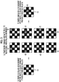
- Fig. 3 is an explanatory diagram of a white-to-black changing process in the ascending-order white-to-black changed threshold value setting step shown in Fig. 2 .
- A) of Fig. 3 is a schematic diagram of a white and black arrangement before the white-to-black changing process.
- (B) of Fig. 3 is a schematic diagram of the white-to-black changing process.
- (C) of Fig. 3 is a schematic diagram of the white and black arrangement after the white-to-black changing process.
- the white and black arrangement 10 before the white-to-black changing process shown in (A) of Fig. 3 is the initial white and black arrangement of the dither mask set in initial white and black arrangement setting step S10 of Fig. 1 in the first white-to-black changing process.
- the white and black arrangement performed through the previous process becomes the white and black arrangement 10 before the white-to-black changing process.
- a white and black arrangement at a threshold value 8 becomes the white and black arrangement 10 before the white-to-black changing process in the first process.
- a white and black arrangement acquired through a process at a threshold value 9 becomes the white and black arrangement 10 before the white-to-black changing process in a process at a threshold value 10.
- the white pixels are temporarily changed to the black pixels one by one, and graininess is evaluated.
- the known index may be applied as an index of the graininess evaluation.
- a standard deviation calculated by applying a blur filter that takes account of RMS granularity, that is, visual perception characteristics of human such as VTF to the white and black arrangement may be used as the index.
- RMS is short for Root Mean Square.
- VTF is short for Visual Transfer Function.
- pixels to be changed to the black pixels are temporarily switched, and the graininess is similarly evaluated.
- the graininess in a case where the white pixels are temporarily changed to the black pixels one by one is evaluated for all the white pixels, and the pixel of which the graininess becomes best is actually changed to the black pixel.
- pixels 12 hatched by diagonal lines are the white pixels to be temporarily changed to the black pixels.
- the graininess is evaluated for eight white and black arrangements shown in (B) of Fig. 3 , and the white pixel of which the graininess becomes best is determined.
- a pixel 16 hatched by diagonal lines is the white pixel of which the graininess becomes best, and is a pixel actually changed to the black pixel from the white pixel.
- the white and black arrangement corresponds to a dot pattern indicating whether or not there is a dot.
- the white-to-black changing process in the ascending-order white-to-black changed threshold value setting step is an aspect of a dot number changing step of adding dots as much as dots corresponding to a gradation difference between a dot pattern determined gradation and a dot pattern determining target gradation, and is a component of a dot pattern determining step.
- the white-to-black changing process in the ascending-order white-to-black changed threshold value setting step is an aspect of the dot number changing step of adding dots as much as dots corresponding to the gradation difference between the dot pattern determined gradation and the dot pattern determining target gradation in a case where a dot pattern determining target gradation is greater than the dot pattern determined gradation.
- a threshold value of the target of the white-to-black changing process in the ascending-order white-to-black changed threshold value setting step is a gradation having a gradation difference of one or more gradations from the dot pattern determined gradation, and corresponds to a dot pattern determining target gradation which a target gradation for determining the dot pattern.
- the white and black arrangement after the white-to-black changing process which is the white and black arrangement determined through the white-to-black changing process is an aspect of a temporary dot pattern with the dot pattern determining target gradation.
- a threshold value in the previous process in the ascending-order white-to-black changed threshold value setting step corresponds to the dot pattern determined gradation.
- the white and black arrangement acquired through the previous process corresponds to a dot pattern with the dot pattern determined gradation.
- a process of changing threshold values of processing targets in the ascending-order white-to-black changed threshold value setting step one by one corresponds to a process of consecutively changing the dot pattern determining target gradation.
- Fig. 4 is an explanatory diagram of the white-to-black changed threshold value setting process in the ascending-order white-to-black changed threshold value setting step shown in Fig. 2 .
- (A) of Fig. 4 is a schematic diagram of the white and black arrangement after the white-to-black changing process.
- (B) of Fig. 4 is a schematic diagram of the white and black dither mask.
- a white and black arrangement 14 after the white-to-black changing process shown in (A) of Fig. 4 is the same white and black arrangement as the white and black arrangement 14 after the white-to-black changing process shown in (C) of Fig. 3 .
- a pixel 16 hatched by diagonal lines in the white and black arrangement 14 after the white-to-black changing process shown in (A) of Fig. 4 is a black pixel actually changed in the white-to-black changing process.
- a threshold value 9 is set for a pixel 22 of the white and black dither mask 20 shown in (B) of Fig. 4 which corresponds to the black pixel 16 actually changed to the black pixel from the white pixel in the white and black arrangement 14 after the white-to-black changing process shown in (A) of Fig. 4 .
- the white-to-black changed threshold value setting process in the ascending-order white-to-black changed threshold value setting step is a component of a threshold value setting step.
- Fig. 5 is an explanatory diagram of a replacement process in the ascending-order replaced threshold value setting step shown in Fig. 2 .
- A) of Fig. 5 is a schematic diagram of a white and black arrangement before the replacement process.
- B) of Fig. 5 is a schematic diagram of the replacement process.
- C) of Fig. 5 is a schematic diagram of a white and black arrangement after the replacement process.
- a white and black arrangement 14 before the replacement process shown in (A) of Fig. 5 is the same white and black arrangement as the white and black arrangement 14 after the white-to-black changing process shown in (A) of Fig. 4 .
- one pixel among all the black pixels in the white and black arrangement 14 before the replacement process shown in (A) of Fig. 5 is set as a target pixel.
- a pixel 24 hatched by dots in (B) of Fig. 5 is a target pixel.
- the target pixel 24 which is the target black pixel is temporarily replaced with all the white pixels one by one, and the graininess is evaluated.
- Pixels 26 hatched by diagonal lines in (B) of Fig. 5 are the white pixels temporarily replaced with the black pixels.
- the target pixel 24 shown in (B) of Fig. 5 is actually replaced with the white pixel of which the graininess becomes best.
- the process of replacing the target pixel 24 shown in (B) of Fig. 5 with the white pixel of which the graininess becomes best is performed while changing the target pixel 24 by a preset number of times of the process.
- an order in which the target pixel 24 is changed such that the black pixel to be replaced with the white pixel is not biased is an order in which a pixel position of the target pixel 24 is randomly changed or an order in which the pixel position is changed without being biased.
- An order in which all the black pixels are replaced is preferable. The details of the number of times of the process will be described below.
- a white and black arrangement 28 after the replacement process shown in (C) of Fig. 5 is a white and black arrangement acquired by actually replacing the target pixel 24 shown in (B) of Fig. 5 with the white pixel of which the graininess becomes best, and is a white and black arrangement acquired by performing the replacement process while changing the target pixel 24 by a preset number of times of the process.
- a pixel 32 and a pixel 34 hatched by dots are pixels changed to the white pixels from the black pixels as the result of the replacement process.
- a pixel 36 and a pixel 38 hatched by diagonal lines are pixels changed to the black pixels from the white pixels as the result of the replacement process.
- the black pixels as the targets of the replacement process include at least one of the black pixels of the white and black arrangement corresponding to the threshold value in the previous process. That is, at least a part of the black pixels in the white and black arrangement 10 before the white-to-black changing process shown in (A) of Fig. 3 is the target of the replacement process.
- the replacement process in the ascending-order replaced threshold value setting step is an aspect of a replacement process of replacing dots including some of dots at the dot pattern determined gradation with non-dot arrangements, and is a component of the dot pattern determining step of performing the replacement process by the preset number of times of the process.
- a step of setting the number of times of the replacement process in the ascending-order replaced threshold value setting step is a component of a replacement process number setting step.
- Fig. 6 is an explanatory diagram of a replaced threshold value setting process in the ascending-order replaced threshold value setting step shown in Fig. 2 .
- A of Fig. 6 is a schematic diagram of the white and black arrangement after the replacement process.
- B of Fig. 6 is a schematic diagram of the white and black dither mask after the replaced threshold value setting process.
- C of Fig. 6 is a schematic diagram of the black and white dither mask after the replaced threshold value setting process.
- a pixel 32 and a pixel 34 hatched by dots in the white and black arrangement 28 after the replacement process are changed to the white pixels from the black pixels through the replacement process.
- a pixel 36 and a pixel 38 hatched by diagonal lines in the white and black arrangement 28 after the replacement process are changed to the black pixels from the white pixels.
- a threshold value 9 is set for a pixel 40 corresponding to the pixel 36 and a pixel 42 corresponding to the pixel 38 in the white and black arrangement 28 after the replacement process shown in (A) of Fig. 6 .
- the pixel 22 is a pixel for which a threshold value 9 is already set through the white-to-black changed threshold value setting process.
- a threshold value 9 is set for a pixel 46 corresponding to the pixel 32 and a pixel 48 corresponding to the pixel 34 in the white and black arrangement 28 after the replacement process shown in (A) of Fig. 6 .
- the threshold value 9 is set for the white and black dither mask 20 and the black and white dither mask 44, the threshold value is increased by one, and the process proceeds to the setting of a threshold value 10. By doing this, the threshold value is set in ascending order until a threshold value 16 is set.
- the replaced threshold value setting process in the ascending-order replaced threshold value setting step is a component of the threshold value setting step.
- the threshold value set for the white and black dither mask corresponds to a first threshold value.
- the threshold value set for the black and white dither mask corresponds to a second threshold value.
- the threshold values are also not set for the white and black dither mask 20 shown in (B) of Fig. 6 and the black and white dither mask 44 shown in (C) of Fig. 6 .
- the replacement process is performed while changing the target pixel 24 shown in (B) of Fig. 5 by a preset number of times of the process.
- the replacement process mentioned herein includes a case where the black pixel and the white pixel are not replaced with each other since the graininess in a case where the target pixel 24 described above is not replaced becomes best.
- the target pixel may be changed by using all the black pixels as the targets, the replacement of all the black pixels with all the white pixels may be performed as one cycle, and the number of cycles may be set as the number of times of the replacement process.
- the processing result before one cycle is used in the second and subsequent cycles of process, and thus, it is possible to improve the graininess whenever the number of times of the replacement process is repeated.
- an order in which the target pixel is changed such that the black pixels to be replaced with the white pixels are not biased is set such that the pixel position of the target pixel is randomly changed or is changed without being biased.
- Figs. 7 and 8 are explanatory diagrams of other examples of the replacement process.
- A) of Fig. 7 is a schematic diagram of the white and black arrangement before the replacement process.
- B) of Fig. 7 is an explanatory diagram of a black specification process.
- C) of Fig. 7 is a schematic diagram of a white and black arrangement after the black specification process.
- FIG. 8 is a schematic diagram of the white and black arrangement after the black specification process, and is the same diagram as (C) of Fig. 7 .
- (B) of Fig. 8 is an explanatory diagram of the replacement process.
- (C) of Fig. 8 is a schematic diagram of the white and black arrangement after the replacement process.
- a white and black arrangement 14 before the replacement process which is the white and black arrangement of the targets of the replacement process shown in (A) of Fig. 7
- one pixel among all the black pixels of the white and black arrangement 14 before the replacement process is temporarily changed to the white pixel, and the graininess is evaluated for the changed pixel as shown in (B) of Fig. 7 .
- Pixels 24A hatched by dots in (B) of Fig. 7 are the black pixels to be temporarily changed to the white pixels.
- the white and black arrangement 14 before the replacement process shown in (A) of Fig. 7 is the same white and black arrangement as the white and black arrangement 14 after the white-to-black changing process shown in (C) of Fig. 3 and the white and black arrangement before the replacement process shown in (A) of Fig. 5 .
- one pixel 24A among all the black pixels of the white and black arrangement 14 before the replacement process is selected is temporarily changed to the white pixel one by one, and the graininess is evaluated.
- the black pixel of which the graininess in a case where the white pixel is changed becomes best is specified.
- a pixel 30A of a white and black arrangement 28A after the black specification process shown in (C) of Fig. 7 is a pixel specified as the black pixel of which the graininess in a case where the black pixel is changed to the white pixel becomes best.
- the specified black pixel 30A is temporarily replaced with all the white pixels of the white and black arrangement 28A after the black specification process shown in (A) of Fig. 8 , and the graininess is evaluated.
- Pixels 26A hatched by diagonal lines in (B) of Fig. 8 are the temporarily replaced white pixels.
- the specified black pixel 30A is actually replaced with the white pixel of which the graininess becomes best, and becomes the white pixel.
- the pixel 26A of the white and black arrangement 31A after the replacement process shown in (C) of Fig. 8 is actually replaced with the pixel 30A, and becomes the black pixel from the white pixel.
- the replacement of the black pixel is repeatedly performed by a preset number of times of the replacement process. Since the graininess of the white and black arrangement before the replacement process becomes best, the replacement of the black pixel and the white pixel includes a case where the replacement of the black pixel and the white pixel is not performed.
- the setting of the threshold value for the white and black dither mask and the black and white dither mask is the same as the example described above, and thus, the description thereof is omitted.
- the ascending-order threshold value setting process shown in Fig. 2 is as follows.
- an energy mask in which a blur filter such as a Gaussian filter is applied with a pixel, which corresponds to each black pixel of the white and black arrangement 10 before the white-to-black changing process shown in (A) of Fig. 3 , as a center is prepared.
- a void pixel which is a pixel of which energy is minimum, among all the white pixels in the white and black arrangement 10 before the white-to-black changing process shown in (A) of Fig. 3 , is changed with the black pixel, and the threshold value to set for the white and black dither mask 20 shown in (B) of Fig. 4 .
- the energy mask is updated by applying the blur filter with the pixel in the white and black arrangement 14 after the white-to-black changing process shown in (A) of Fig. 4 , which corresponds to the pixel for which the threshold value is set in the white and black dither mask 20 shown in (B) of Fig. 4 , as the center.
- one pixel among all the black pixels in the white and black arrangement 14 before the replacement process shown in (A) of Fig. 5 is initially set as the target pixel 24 as shown in (B) of Fig. 5 .
- the target pixel 24 is changed to the white pixel as shown in (B) of Fig. 5 .
- the blur filter is removed with the changed target pixel 24 as the center, and the energy mask is updated.
- the void pixel which is the pixel of which the energy is minimum, among all the white pixels including the target pixel 24 changed to the white pixel from the black pixel, is changed to the black pixel.
- the energy mask is updated by applying the blur filter with the pixel changed to the black pixel, and the threshold value is set for the white and black dither mask shown in (B) of Fig. 6 and the black and white dither mask shown in (C) of Fig. 6 .
- the replacement process is performed while changing the target pixel by a preset number of times of the process.
- the replacement process mentioned herein includes a case where the replacement of the black pixel and the white pixel is not performed since the energy of the target pixel 24 described above is minimum.
- an order in which the target pixel 24 is changed is an order in which a pixel position of the target pixel 24 is randomly changed or an order in which the pixel position is changed without being biased. An order in which all the black pixels are replaced is preferable.
- the target pixel may be changed by using all the black pixels as the targets, the replacement of all the black pixels with all the white pixels may be performed as one cycle, and the number of cycles may be set as the number of times of the replacement process.
- the ascending-order replaced threshold value setting step S22 shown in Fig. 2 may be as follows.
- the pixel 30A of the white and black arrangement 28A after the black specification process shown in (C) of Fig. 7 is the pixel specified as the black pixel of which the energy is maximum.
- the blur filter is removed with the pixel 30A changed to the white pixel as the center, and the energy mask is updated.
- the energy mask is updated by changing the void pixel which is the pixel of which the energy is minimum, among all the white pixels, to the black pixel and applying the blur filter with the pixel changed to the black pixel as the center, and the threshold value is set for the white and black dither mask and the black and white dither mask.
- the replacement of the black pixel is repeatedly performed by a preset number of times of the process.
- the replacement process mentioned herein includes a case where the replacement of the black pixel and the white pixel is not performed since the energy of the specified pixel 30A is minimum as described above.
- the threshold value is not set for the white and black dither mask and the black and white dither mask. Specifically, in a case where the threshold value is set for any pixel of the white and black dither mask, it is checked whether or not the same threshold value is already set for the corresponding pixel of the black and white dither mask. In a case where the same threshold value is set for the corresponding pixels of the black and white dither mask, the threshold values of the pixels of the white and black dither mask and the black and white dither mask are removed.
- the threshold value is set for any pixel of the black and white dither mask, it is checked whether or not the same threshold value is already set for the corresponding pixel of the white and black dither mask. In a case where the same threshold value is already set for the corresponding pixel of the white and black dither mask, the threshold values of the pixels of the black and white dither mask and the white and black dither mask are removed.
- the ascending-order threshold value setting step has been described above according to the procedure of Fig. 2 .
- the order of ascending-order white-to-black changed threshold value setting step S20 and ascending-order replaced threshold value setting step S22 in the procedure of Fig. 2 may be reversed.
- the white and black arrangement after the replacement process may be initially determined and the threshold value may be set for the white and black dither mask and the black and white dither mask by performing the replacement process on the white and black arrangement at the dot pattern determined gradation by the preset number of times of the process in ascending-order replaced threshold value setting step S22.
- the white and black arrangement at the dot pattern determining target gradation may be determined and the threshold value may be set for or may be removed from the white and black dither mask and the black and white dither mask by adding the dots as much as the dots corresponding to the gradation difference between the dot pattern determined gradation and the dot pattern determining target gradation to the white and black arrangement after the replacement process in ascending-order white-to-black changed threshold value setting step S20.
- the aspect in which ascending-order replaced threshold value setting step S22 is performed and ascending-order white-to-black changed threshold value setting step S20 is subsequently performed is an aspect of a dot pattern determining step of performing a replacement processing step and subsequently performing a dot number changing step.
- Fig. 9 is a flowchart showing a flow of the procedure of the descending-order threshold value setting step shown in Fig. 1 .
- the process of increasing the threshold value of the ascending-order threshold value setting step described above one by one is a process of decreasing the threshold value one by one.
- the process of temporarily changing one white pixel to the black pixel in the ascending-order threshold value setting step and evaluating the graininess is a process of temporarily changing one black pixel to the white pixel and evaluating the graininess.
- the threshold values from 8 to 1 are set.
- a descending-order threshold value setting process in the descending-order threshold value setting step includes descending-order black-to-white changed threshold value setting step S30, descending-order replaced threshold value setting step S32, and descending-order threshold value setting completion determination step S34.
- the steps from descending-order black-to-white changed threshold value setting step S30 to descending-order threshold value setting completion determination step S34 are repeatedly performed until the threshold values are set for all the threshold value setting target pixels of the dither mask. Meanwhile, in a case where the threshold value is set for all the threshold value setting target pixels of the dither mask, the descending-order threshold value setting step is ended.
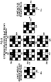
- Fig. 10 is an explanatory diagram of a black-to-white changing process in the descending-order black-to-white changed threshold value setting step shown in Fig. 9 .
- A) of Fig. 10 is a schematic diagram of a white and black arrangement before the black-to-white changing process.
- (B) of Fig. 10 is a schematic diagram of the black-to-white changing process.
- (C) of Fig. 10 is a schematic diagram of a white and black arrangement after the black-to-white changing process.
- a white and black arrangement 50 after the black-to-white changing process shown in (A) of Fig. 10 is the initial white and black arrangement of the dither mask set in the initial white and black arrangement setting step S10 of Fig. 1 in a first black-to-white changing process.
- Pixels 52 hatched by dots in (B) of Fig. 10 are the black pixels to be temporarily changed to the white pixels one by one.
- the graininess is evaluated for eight white and black arrangements shown in (B) of Fig. 10 , and the white and black arrangement of which the graininess becomes best is determined.
- a pixel 56 hatched by dots in a white and black arrangement 54 after the black-to-white changing process shown in (C) of Fig. 10 is a black pixel of which the graininess becomes best, and is a pixel actually changed to the white pixel from the black pixel.
- the known index may be applied as the index of the graininess, and thus, the description thereof is omitted.
- the black-to-white changing process in the descending-order black-to-white changed threshold value setting step is an aspect of a dot number changing determination process of removing dots as much as dots corresponding to a gradation difference between a dot pattern determined gradation and a dot pattern determining target gradation, and is a component of the dot pattern determining step.
- the black-to-white changing process in the descending-order black-to-white changed threshold value setting step is an aspect of a dot number changing step of removing dots as much as dots corresponding to a gradation difference between a dot pattern determined gradation and a dot pattern determining target gradation in a case where the dot pattern determining target gradation is less than the dot pattern determined gradation.
- the white and black arrangement after the black-to-white changing process which is the white and black arrangement determined through the black-to-white changing process is an aspect of a temporary dot pattern in the dot pattern determining target gradation.
- a threshold value of the target of the black-to-white changing process in the descending-order black-to-white changed threshold value setting step is a gradation having a gradation difference of one or more gradations from the dot pattern determined gradation, and corresponds to a dot pattern determining target gradation which is a gradation of the target for determining the dot pattern.
- a process of changing threshold values of processing targets in the descending-order black-to-white changed threshold value setting step one by one corresponds to a process of consecutively changing the dot pattern determining target gradation.
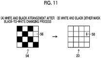
- Fig. 11 is an explanatory diagram of a black-to-white changed threshold value setting process in the descending-order black-to-white changed threshold value setting step shown in Fig. 9 .
- (A) of Fig. 11 is a schematic diagram of the white and black arrangement after the black-to-white changing process.
- (B) Fig. 11 is a schematic diagram of the white and black dither mask.
- a white and black arrangement 54 after the black-to-white changing process shown in (A) of Fig. 11 is the same as the white and black arrangement 54 after the black-to-white changing process shown in (C) of Fig. 10 .
- a pixel 56 hatched by dots is the white pixel actually changed in the black-to-white changing process.
- a threshold value 8 is set for a pixel 58 in a white and black dither mask 20 shown in (B) of Fig. 11 , which corresponds to the pixel 56 changed to the white pixel from the black pixel in the white and black arrangement 54 after the black-to-white changing process.
- the threshold values in the ascending order are the threshold values for changing the white pixels to the black pixels
- the threshold values in the descending order are the threshold values for returning the changed white pixels to the black pixels.
- the black-to-white changed threshold value setting process in the descending-order black-to-white changed threshold value setting step is a component in the threshold value setting step.
- Fig. 12 is an explanatory diagram of the replacement process in the descending-order replaced threshold value setting step shown in Fig. 9 .
- A) of Fig. 12 is a schematic diagram of the white and black arrangement before the replacement process.
- B) of Fig. 12 is a schematic diagram of the replacement process.
- C) of Fig. 12 is a schematic diagram of the white and black arrangement after the replacement process.
- the white and black arrangement 54 before the replacement process shown in (A) of Fig. 12 is the same as the white and black arrangement 54 after the black-to-white changing process on which the black-to-white changing process shown in (A) of Fig. 11 has been performed.
- one pixel among all the black pixels in the white and black arrangement 54 before the replacement process shown in (A) of Fig. 12 is set as the target pixel.
- a pixel 60 hatched by dots in (B) of Fig. 12 is the target pixel.
- the target pixel 60 which is the target black pixel is temporarily replaced with all the white pixels one by one, and graininess is evaluated.
- Pixels 62 hatched by diagonal lines in (B) of Fig. 12 are the white pixels temporarily replaced with the black pixels.
- the target pixel 60 shown in (B) of Fig. 12 is actually replaced with the white pixel of which the graininess becomes best.
- the process of replacing the target pixel 60 shown in (B) of Fig. 12 with the white pixel of which the graininess becomes best is performed while changing the target pixel 60 by a preset number of times of the process.
- the target pixel 60 is changed in an order without being biased such as a random order such that the black pixel to be replaced with the white pixel is not biased and in an order in which all the black pixels are performed as one cycle.
- the number of times of the process is the same as the ascending-order threshold value setting step S14 described above, and the description thereof is omitted.
- a white and black arrangement 64 after the replacement process shown in (C) of Fig. 12 is a white and black arrangement acquired by actually replacing the target pixel 60 shown in (B) of Fig. 12 with the white pixel of which the graininess becomes best, and is a white and black arrangement on which the replacement process has been performed while changing the target pixel 60 by a preset number of times of the process.
- a pixel 66 and a pixel 68 hatched by dots are pixels changed to the white pixels from the black pixels as the result of the replacement process.
- a pixel 70 and a pixel 72 hatched by diagonal lines are pixels changed to the black pixels from the white pixels as the result of the replacement process.
- the black pixel as the target of the replacement process includes all the black pixels. That is, all the black pixels in the white and black arrangement 54 before the replacement process shown in (A) of Fig. 12 are the targets of the replacement process. As the result of the replacement process, some of the black pixels in the white and black arrangement 54 before the replacement process are changed to the white pixels.
- the replacement process in the descending-order replaced threshold value setting step is an aspect of a replacement process of replacing dots including some of dots at the dot pattern determined gradation with the non-dot arrangements, and is a component of the dot pattern determining step of performing the replacement process by the preset number of times of the process.
- a step of setting the number of times of the replacement process in the descending-order replaced threshold value setting step is a component of a replacement process number setting step.
- Fig. 13 is an explanatory diagram of a replaced threshold value setting process in the descending-order replaced threshold value setting step shown in Fig. 9 .
- A) of Fig. 13 is a schematic diagram of the white and black arrangement after the replacement process.
- B) of Fig. 13 is a schematic diagram of the white and black dither mask after the replaced threshold value setting process.
- C) of Fig. 13 is a schematic diagram of the black and white dither mask after the replaced threshold value setting process.
- a pixel 66 and a pixel 68 hatched by dots in the white and black arrangement 64 after the replacement process are changed to the white pixels from the black pixels through the replacement process.
- a pixel 70 and a pixel 72 hatched by diagonal lines in the white and black arrangement 64 after the replacement process are changed to the black pixels from the white pixels.
- a threshold value 8 is set for a pixel 74 corresponding to the pixel 66 and a pixel 76 corresponding to the pixel 68 hatched by dots in the white and black arrangement 64 after the replacement process shown in (A) of Fig. 13 .
- the pixel 58 is a pixel for which a threshold value 8 is already set through the black-to-white changed threshold value setting process.
- a threshold value 8 is set for a pixel 78 corresponding to the pixel 70 and a pixel 80 corresponding to the pixel 72 in the white and black arrangement 64 after the replacement process shown in (A) of Fig. 13 .
- the threshold value is decreased by one, and the process proceeds to the setting of a threshold value 7. By doing this, the threshold values are set in the descending order until a threshold value 1 is set.
- the replaced threshold value setting process in the descending-order replaced threshold value setting step is a component of the threshold value setting step.
- the replacement of the black pixels to the white pixel may be performed while changing the target pixel 60 shown in (B) of Fig. 12 by the preset number of times of the process.
- the target pixel may be changed by using all the black pixels as the targets, the replacement of all the black pixels with all the white pixels may be performed as one cycle, and the number of cycles may be set as the number of times of the replacement process.
- the number of times of the replacement process may be set for each threshold value.
- the processing result before one cycle is used in the second and subsequent cycles of process, and thus, it is possible to improve the graininess whenever the number of times of the replacement process is repeated.
- the descending-order threshold value setting process shown in Fig. 9 is as follows.
- the blur filter is removed with the pixel in the white and black arrangement 54 after the black-to-white changing process shown in (A) of Fig. 11 , which corresponds to the pixel for which the threshold value is set in the white and black dither mask 20 shown in (B) of Fig. 11 , as the center, and the energy mask is updated.
- one pixel among all the black pixels in the white and black arrangement 54 before the replacement process shown in (A) of Fig. 12 is set as the target pixel 60 shown in (B) of Fig. 12 .
- the target pixel 60 is changed to the white pixel, as shown in (B) of Fig. 12 .
- the blur filter is removed with the target pixel 60 changed to the white pixel as the center, and the energy mask is updated.
- the void pixel which is the pixel of which the energy is minimum, among all the white pixels including the white pixel changed to the white pixel from the black pixel, is changed to the black pixel.
- the energy mask is updated by applying the blur filter with the white pixel changed to the black pixel as the center, and the threshold value is set for the white and black dither mask 20 shown in (B) of Fig. 13 and the black and white dither mask 44 shown in (C) of Fig. 13 .
- the replacement process is performed while changing the target pixel 60 by the preset number of times of the process.
- the replacement process mentioned herein includes a case where the replacement of the black pixel and the white pixel is not performed since the energy of the target pixel 60 described above is minimum.
- the pixel position of the target pixel 60 is randomly changed or is changed without being biased. It is preferable that the pixel of the position thereof is changed in an order in which all the black pixels are changed.
- the target pixel may be changed by using all the black pixels as the targets, the replacement of all the black pixels with all the white pixels may be performed as one cycle, and the number of cycles may be set as the number of times of the replacement process.
- the descending-order replaced threshold value setting step S32 shown in Fig. 9 may be as follows.
- One cluster pixel which is the pixel of which the energy is maximum, among all the black pixels in the white and black arrangement 54 before the replacement process shown in (A) of Fig. 12 , is specified, and is changed to the white pixel.
- the blur filter is removed with the pixel changed to the white pixel as the center, and the energy mask is updated.
- the replacement of the black pixel is repeatedly performed by a preset number of times of the process.
- the replacement process mentioned herein includes a case where the replacement of the black pixel and the white pixel is not performed since the energy of the specified pixel is minimum as described above.
- the changed white pixel may be returned to the black pixel again while maintaining the same threshold value.
- the changed black pixel may be returned to the white pixel again while maintaining the same threshold value.
- the threshold value is not set for the white and black dither mask and the black and white dither mask. Specifically, in a case where the threshold value is set for any pixel of the white and black dither mask, it is checked whether or not the same threshold value is already set for the corresponding pixel of the black and white dither mask. In a case where the same threshold value is already set for the corresponding pixel of the black and white dither mask, the threshold values of the pixels for which the same threshold value is set in the white and black dither mask and the black and white dither mask are removed.
- the threshold value is set for any pixel of the black and white dither mask, it is checked whether or not the same threshold value is already set for the corresponding pixel of the white and black dither mask. In a case where the same threshold value is already set for the corresponding pixel of the white and black dither mask, the threshold values of the pixels for which the same threshold value is set in the black and white dither mask and the white and black dither mask are removed.
- the descending-order threshold value setting step has been described according to the procedure of Fig. 9 .
- the orders of the black-to-white changed threshold value setting step and the replaced threshold value setting step may be reversed.
- the white and black arrangement after the replacement process may be initially determined and the threshold value may be set for the white and black dither mask and the black and white dither mask by performing the replacement process on the white and black arrangement at the dot pattern determined gradation by the preset number of times of the process in descending-order replaced threshold value setting step S32.
- the white and black arrangement at the dot pattern determining target gradation may be determined and the threshold value may be set for or may be removed from the white and black dither mask and the black and white dither mask by removing the dots as much as the dots corresponding to the gradation difference between the dot pattern determined gradation and the dot pattern determining target gradation from the white and black arrangement after the replacement process in descending-order black-to-white changed threshold value setting step S30.
- the aspect in which the descending-order replaced threshold value setting step S32 is performed and the descending-order black-to-white changed threshold value setting step S30 is subsequently performed is an aspect of the dot pattern determining step of performing the replacement processing step and subsequently performing the dot number changing step.
- FIG. 14 is a schematic diagram of the white and black arrangement for which the threshold value is set in the ascending-order white-to-black changed threshold value setting step S20 of the ascending-order threshold value setting step.
- (B) of Fig. 14 is a schematic diagram of the white and black dither mask corresponding to (A) of Fig. 14 .
- a white and black arrangement 100 shown in (A) of Fig. 14 has a size of 81 pixels in 9 pixels ⁇ 9 pixels.
- a two-digit number assigned to each pixel of the white and black arrangement 100 represents a position of the pixel.
- the tens place represents a row number, and the ones place represents a column number.
- Pixels colored in black in the white and black arrangement 100 shown in (A) of Fig 14 represent the black pixels. Pixels colored in white in the white and black arrangement 100 are the white pixels. The black pixel of which the pixel position in the white and black arrangement 100 is 76 is the pixel for which the threshold value is set.
- a threshold value 20 is set for a pixel 104 corresponding to the black pixel of which the black pixel position of the white and black arrangement 100 of (A) of Fig. 14 is 76.
- the pixels colored in black in the white and black dither mask 102 shown in (B) of Fig. 14 are pixels for which threshold values from 1 to 19 are set.
- FIG. 15 is a schematic diagram of the white and black arrangement acquired by changing one black pixel to the white pixel through the replacement process in the ascending-order replaced threshold value setting step S22.
- (B) of Fig. 15 is a schematic diagram of the black and white dither mask for which the threshold value is set so as to correspond to (A) of Fig. 15 .
- a threshold value 20 is set for a pixel 110 corresponding to the white pixel of which the pixel position of the white and black arrangement 106 shown in (A) of Fig. 15 is 35.
- a plurality of threshold values other than a threshold value 20 may be set for the pixel for which a threshold value 20 is set.
- the threshold values in the same pixels of the white and black dither mask 102 and the black and white dither mask 108 are alternately set, and thus, a minimum value and a maximum value of these threshold values belong to the white and black dither mask 102.
- any pixel of the white and black dither mask 102 are a first white-to-black threshold value, a second white-to-black threshold value, ⁇ , and a P-th white-to-black threshold value and (P-1) threshold values in the pixel of the black and white dither mask 108 are a first black-to-white threshold value, a second black-to-white threshold value, ⁇ , and a (P-1)-th black-to-white threshold value
- first white-to-black threshold value ⁇ first black-to-white threshold value ⁇ second white-to-black threshold value ⁇ second black-to-white threshold value ⁇ ⁇ ⁇ (P-1)-th black-to-white threshold value ⁇ P-th white-to-black threshold value is satisfied.
- the minimum value or the maximum value of the plurality of threshold values in the same pixels of the white and black dither mask 102 and the black and white dither mask 108 do not necessarily belong to the white and black dither mask 102.
- FIG. 16 is a schematic diagram of the white and black arrangement acquired by replacing one black pixel and the white pixel through the replacement process in the ascending-order replaced threshold value setting step S22, that is, a schematic diagram of the white and black arrangement setting step acquired by changing one black pixel to the white pixel and changing another white pixel to the black pixel.
- (B) of Fig. 16 is a schematic diagram of the white and black dither mask for which the threshold value is set so as to correspond to (A) of Fig. 16 .
- a threshold value 20 is set for a pixel 114 corresponding to the black pixel of which the pixel number of the white and black arrangement 112 shown in (A) of Fig. 16 is 55.
- Pixels colored in black in the white and black dither mask 102 shown in (B) of Fig. 16 are pixels for which threshold values from 1 to 19 are set.
- the dither mask constituted by 16 pixels of 4 pixels ⁇ 4 pixels and the dither mask having the size of 81 pixels of 9 pixels ⁇ 9 pixels have been used as the examples.
- the dither mask manufacturing method described in the present embodiment is not limited to the manufacturing of the dither masks having these sizes, but may be applied to the manufacturing of a dither mask having a certain number of pixels.
- the white and black dither mask that stores the threshold value at which the white pixel is changed to the black pixel and the black and white dither mask that stores the threshold value at which the black pixel is changed to the white pixels are provided as the dither mask.
- the threshold values in the pixels of the white and black dither mask and the threshold values in the pixels of the black and white dither mask are alternately set. That is, in a case where the threshold values in the pixels of the white and black dither mask are the first white-to-black threshold value, the second white-to-black threshold value, ⁇ , and the P-th white-to-black threshold value in ascending order and the pixels of the black and white dither mask are the first black-to-white threshold value, the second black-to-white threshold value, ⁇ , and the (P-1)-th black-to-white threshold value in ascending order, the relationship of first white-to-black threshold value ⁇ first black-to-white threshold value ⁇ second white-to-black threshold value ⁇ second black-to-white threshold value ⁇ ⁇ ⁇ (P-1)-th black-to-white threshold value ⁇ P-th white-to-black threshold value is satisfied.
- P represents the number of threshold values in each pixel of the white and black dither mask, and has a different value for each pixel.
- the first white-to-black threshold value is not necessarily minimum in a case where the black pixels remain even at the minimum gradation
- the P-th white-to-black threshold value is not necessarily maximum in a case where the white pixels remain even at the maximum gradation.
- the number of threshold values of the same pixel of the black and white dither mask is not necessarily (P-1) with respect to the number P of threshold values of the white and black dither mask.
- the number of threshold values of each pixel of the white and black dither mask and the number of threshold values of each pixel of the black and white dither mask are retained apart from the white and black dither mask and the black and white dither mask.
- Fig. 17 is a flowchart showing a flow of a procedure of the halftone process.
- Fig. 17 shows the procedure of the halftone process in a case where the number of threshold values of the white and black dither mask is P and the number of threshold values of the black and white dither mask is P-1.
- the pixel is typically the white pixel at the minimum gradation.
- the minimum threshold value is the first white-to-black threshold value.
- the pixel is the black pixel at the maximum gradation.
- the maximum threshold value is the P-th white-to-black threshold value.
- an image value for each pixel is acquired from image data in image value acquisition step S40.
- white and black first determination step S42 it is determined whether or not an image value is less than the first white-to-black threshold value stored in the white and black dither mask.
- white and black first determination step S42 the pixel of which the image value is determined to be less than the first white-to-black threshold value is allocated to the white pixel in allocation step S44, and the processing of the pixel is completed. This procedure is a case where the determination result in white and black first determination step S42 is YES.
- white and black first determination step S42 the processing of the pixel of which the image value is determined to be equal to or greater than the first white-to-black threshold value proceeds to a black and white first determination step S46.
- This procedure is a case where the determination result in white and black first determination step S42 is NO.
- black and white first determination step S46 it is determined whether or not the image value is less than the first black-to-white threshold value stored in the black and white dither mask.
- black and white first determination step S46 the pixel of which the image value is determined to be less than the first black-to-white threshold value is allocated to the black pixel in allocation step S48, and the processing of the pixel is completed. This procedure is a case where the determination result in black and white first determination step S46 is YES.
- black and white first determination step S46 the processing of the pixel of which the image value is determined to be equal to or greater than the first black-to-white threshold value proceeds to white and black second determination step S50.
- This procedure is a case where the determination result in black and white first determination step S46 is NO.
- white and black second determination step S50 it is determined whether or not the image value is less than the second white-to-black threshold value stored in the white and black dither mask.
- white and black second determination step S50 the pixel of which the image value is determined to be less than the second white-to-black threshold value is allocated to the white pixel in allocation step S52, and the processing of the pixel is completed. This procedure is a case where the determination result in white and black second determination step S50 is YES.
- white and black second determination step S50 the processing of the pixel of which the image value is determined to be equal to or greater than the second white-to-black threshold value proceeds to the black and white second determination step.
- This procedure is a case where the determination result in white and black second determination step S50 is NO.
- Fig. 17 the illustration of the black and white second determination step is omitted.
- the comparison of the image value with the white-to-black threshold value or the comparison of the image value with the black-to-white threshold value are sequentially performed, and the processing target pixel is allocated to the black pixel or the white pixel.
- the pixel of which the image value is determined to be less than the (P-1)-th black-to-white threshold value is allocated to the black pixel in allocation step S56, and the processing of the pixel is completed.
- This procedure is a case where the determination result in black and white (P-1)-th determination step S54 is YES.
- black and white (P-1)-th determination step S54 the processing of the pixel of which the image value is determined to be equal to or greater than the (P-1)-th black-to-white threshold value proceeds to white and black P-th determination step S58.
- This procedure is a case where the determination result in black and white (P-1)-th determination step S54 is NO.
- white and black P-th determination step S58 it is determined whether or not the image value is less than the P-th white-to-black threshold value stored in the white and black dither mask.
- the pixel of which the image value is determined to be less than the P-th white-to-black threshold value is allocated to the white pixel in allocation step S60, and the processing of the pixel is completed.
- This procedure is a case where the determination result in white and black P-th determination step S58 is YES.
- white and black P-th determination step S58 the pixel of which the image value is determined to be equal to or greater than the P-th white-to-black threshold value is allocated to the black pixel in allocation step S62, and the processing of the pixel is completed.
- This procedure is a case where the determination result in white and black P-th determination step S58 is NO.
- the halftone process is completed by sequentially comparing the image value of the processing target pixel with the threshold values from the first white-to-black threshold value to the P-th white-to-black threshold value and allocating each pixel to the black pixel or the white pixel based on the comparison result.
- the P-th black-to-white threshold value may be present as the maximum threshold value.
- the presence or absence of the P-th black-to-white threshold value may be determined based on the number of black-to-white threshold values with respect to the number P of white-to-black threshold values. That is, it may be determined that the P-th black-to-white threshold value is present in a case where the number of black-to-white threshold values is P, and it may be determined that P-th black-to-white threshold value is not present in a case where the number of black-to-white threshold values is P-1.
- the black and white P-th determination step of determining whether or not the image value is less than the P-th black-to-white threshold value may be added after white and black P-th determination step S58 of Fig. 17 , the pixel is may be allocated to the black pixel in a case where the image value is less than the P-th black-to-white threshold value, and the pixel may be allocated to the white pixel in a case where the image value is equal to or greater than the P-th black-to-white threshold value.
- the first white-to-black threshold value and the first black-to-white threshold value are compared, and the halftone process is performed according to the flowchart shown in Fig. 18 instead of the flowchart shown in Fig. 17 in a case where the first black-to-white threshold value is less than the first white-to-black threshold value.
- Fig. 18 is a flowchart showing a flow of a procedure of another aspect of the halftone process.
- the pixel becomes the black pixel at the maximum gradation, that is, the pixel becomes the P-th white-to-black threshold value at the maximum threshold value.
- the same steps in Fig. 18 as those in Fig. 17 are assigned the same references, and thus, the description thereof will be appropriately omitted.
- the black and white P-th determination step S59 shown in Fig. 18 is added before white and black P-th determination step S58 in the flowchart shown in Fig. 17 .
- Allocation step S61 is added along with the addition of black and white P-th determination step S59.
- the processing contents in the steps are the same as those in the flowchart shown in Fig. 17 , and thus, the description thereof is omitted.
- the halftone process is completed by sequentially the image value of the processing target pixel with each threshold value from the first black-to-white threshold value to the P-th white-to-black threshold value and allocating each pixel to the black pixel or the white pixel based on the comparison result.
- a (P+1)-th black-to-white threshold value may be present.
- the presence or absence of the (P+1)-th black-to-white threshold value may be determined similarly to the presence or absence of the P-th black-to-white threshold value in the description of the flowchart shown in Fig. 17 .
- the presence or absence of the (P+1)-th black-to-white threshold value may be determined based on the number of black-to-white threshold values with respect to the number P of white-to-black threshold values. That is, it may be determined that the (P+1)-th black-to-white threshold value is present in a case where the number of black-to-white threshold values is P+1, and it may be determined that the (P+1)-th black-to-white threshold value is not present in a case where the number of black-to-white threshold values is P.
- the presence or absence of the (P+1)-th black-to-white threshold value may be determined even though the maximum values of the white-to-black threshold values and the black-to-white threshold values are compared. That is, it may be determined that the (P+1)-th black-to-white threshold value is present in a case where the maximum value of the threshold values is the black-to-white threshold value, and it may be determined that the (P+1)-th black-to-white threshold value is not present in a case where the maximum value of the threshold values is the white-to-black threshold value.
- the black-to-white (P+1)-th determination step of determining whether or not the image value is less than the (P+1)-th black-to-white threshold value may be added after the white and black P-th determination step S58 of Fig. 18 , the pixel may be allocated to the black pixel in a case where the image value is less than the (P+1)-th black-to-white threshold value, and the pixel may be allocated to the white pixel in a case where the image value is equal to or greater than the (P+1)-th black-to-white threshold value.
- the halftone process corresponds to a halftone process for creating a halftone image by converting multivalued image data.
- the dither mask is an aspect of a halftone mask.
- a set of white and black arrangements corresponding to the threshold values of the dither mask may be manufactured as the halftone mask.
- a dither mask having a size of 256 pixels ⁇ 256 pixels memory capacity of 2 bytes per pixel is required in order to store threshold values from 1 to 65536.
- the number of times of the replacement process of ascending-order replaced threshold value setting step S22 of Fig. 2 or the replacement process of descending-order replaced threshold value setting step S32 of Fig. 9 becomes larger, the number of threshold values to be set for each pixel of the white and black dither mask and the black and white dither mask becomes larger. Accordingly, the memory capacity for storing the white and black dither mask and the black and white dither mask may be increased.
- the white and black arrangement may have only the memory capacity of one byte per pixel.
- the gradation of the image value is a gradation which is smaller than 65536, for example, 256
- the white and black arrangement corresponding to a gradation of 256 may be stored.
- the white and black arrangement is stored, since the white and black arrangement is directly allocated from the image value of each pixel, a processing period of the halftone process is also advantageous.
- one dither mask includes two kinds of threshold values of the threshold value at which the white pixel is changed to the black pixel and the threshold value at which the black pixel is changed to the white pixel may be used as an example.
- the stacking limitations of the dither mask are partially eliminated, and the white and black arrangement at each density is independently optimized to some extent.
- the image quality is more favorable compared to a case where the dither mask of the related art is used.
- the stacking limitations of the dither mask are partially maintained, and thus, it is possible to secure constant continuity in the white and black arrangements between the densities.
- the graininess is evaluated as the evaluation of the image quality
- image quality other than the graininess such as unevenness in density or unevenness in color may be evaluated.
- the density mentioned herein may be referred to as the image value, the gradation, or the number of gradations.
- the white and black arrangement is determined by increasing or decreasing the threshold value one by one and adding the black pixel or the white pixel one by one and the threshold value is set for the dither mask so as to correspond to the determined white and black arrangement has been described.
- the white and black arrangement is determined by increasing or decreasing the threshold value by two or more and adding the black pixels or the white pixels as much as the pixels corresponding to the value by which the threshold value is increased or decreased, and the threshold value is set for the dither mask based on the determined white and black arrangement.
- the step of determining the white and black arrangement by adding the black pixels or the white pixels as much as the pixels corresponding to the value by which the threshold value is increased or decreased is a component of a dot pattern determining step of determining a dot pattern in a dot pattern determining target gradation having a difference in the number of gradations of two or more gradations from the dot pattern determined gradation.
- Fig. 19 is a flowchart showing a flow of a procedure of the dither mask manufacturing method according to the second embodiment.
- Fig. 20 is a schematic diagram of the dither mask manufacturing method according to the second embodiment.
- the image value is expressed by 256 gradations from 0 to 255
- the size of the dither mask is 256 pixels of 16 pixels ⁇ 16 pixels
- the threshold value interval is 16, and 0, 16, 32, 48, 64, 80, 96, 112, 128, 144, 160, 176, 192, 208, 224, 240, and 256 are section threshold values will be described.
- the dither mask manufacturing method includes initial white and black arrangement setting step S70, descending-order white and black arrangement determining step S72, ascending-order white and black arrangement determining step S74, descending-order threshold value setting step S76, and ascending-order threshold value setting step S78.
- the descending-order threshold value setting step and the ascending-order threshold value setting step are components of the threshold value setting step.
- initial white and black arrangement setting step S70 is set in initial white and black arrangement setting step S70.
- Initial white and black arrangement setting step S70 shown in Fig. 19 is the same as initial white and black arrangement setting step S10 shown in Fig. 1 , and the description thereof is omitted.
- the black pixel is sequentially decreased in descending order at an interval of two or more threshold values, and a white and black arrangement corresponding to a section threshold value for each interval of two threshold values is determined.
- a white and black arrangement 202 acquired by decreasing the black pixel from the initial white and black arrangement 200 by 16 threshold values is determined.
- the initial white and black arrangement 200 according to the present embodiment has the number of black pixels and the number of white pixels corresponding to a threshold value 128 which is a reference threshold value.
- the reference threshold value is a threshold value at which descending-order white and black arrangement determining step S72 and ascending-order white and black arrangement determining step S74 are switched.
- a dither mask 220 shown in Fig. 20 is acquired by integrating the white and black dither mask and the black and white dither mask according to the first embodiment.
- a first threshold value which is a threshold value at which the white pixel is changed to the black pixel is set for each pixel of the dither mask 220.
- a second threshold value which is a threshold value at which the black pixel is changed to the white pixel may be set.
- a white and black arrangement 204 acquired by decreasing the black pixel from the white and black arrangement 202 by 16 threshold values is determined.
- the black pixel is decreased by 16 threshold values until all the pixels become the white pixels, and the white and black arrangement is determined for each section threshold value with the white and black arrangement corresponding to a previous section threshold value as a reference.
- the black pixel is sequentially increased in ascending order at an interval of two or more threshold values, and a white and black arrangement corresponding to a separation threshold value for each interval of two threshold values is determined. As shown in Fig. 20 , the black pixel is increased from the initial white and black arrangement 200 by 16 threshold values, and a white and black arrangement 212 is determined.
- the black pixel is increased from the white and black arrangement 212 by 16 threshold values, and a white and black arrangement 214 is determined.
- the black pixel is increased by 16 threshold values until all the pixels become the black pixels, and the white and black arrangements are determined for the section threshold values with the white and black arrangement corresponding to the previous section threshold value as the reference.
- the threshold values are set from the threshold value corresponding to the initial white and black arrangement in descending order based on the white and black arrangement corresponding to each section threshold value.
- a threshold value 128 to a threshold value 113 are set for the dither mask 220 in descending order based on the white and black arrangement 200 and the white and black arrangement 202 shown in Fig. 20 .
- a threshold value 112 to a threshold value 97 are set for the dither mask 220 in descending order based on the white and black arrangement 202 and the white and black arrangement 204.
- White and black arrangements are determined for intermediate threshold values between the section threshold values such that continuity with the white and black arrangement of the section threshold value is maintained, and the corresponding threshold value is set for the dither mask 220.
- a white and black arrangement 201A, a white and black arrangement 201B, ⁇ , a white and black arrangement 201C, and a white and black arrangement 201D are determined for an intermediate threshold value 127, an intermediate threshold value 126, ⁇ , an intermediate threshold value 114, and an intermediate threshold value 113 between the section threshold value 128 and the section threshold value 112 such that the continuity of the white and black arrangement 200 of the section threshold value 128 and the white and black arrangement 202 of the section threshold value 112 is maintained.
- the white and black arrangement 201A is determined, and thus, the threshold value 128 is set for the dither mask 220.
- the white and black arrangement 201B, ⁇ , the white and black arrangement 201C, and the white and black arrangement 201D are determined, and thus, the threshold value 127, ⁇ , the threshold value 115, the threshold value 114 are set for the dither mask 220.
- the white and black arrangement 201D is determined, and thus, the threshold value 113 is set for the dither mask 220 based on the difference from the white and black arrangement 202 of the section threshold value 112.
- the threshold values are set from the threshold value corresponding to the initial white and black arrangement by one or more threshold values in ascending order based on the white and black arrangements corresponding to the section threshold values.
- the threshold value 129 to the threshold value 144 are set for the dither mask 220 in ascending order based on the white and black arrangement 200 and the white and black arrangement 212 shown in Fig. 20 .
- the threshold value 145 to the threshold value 160 are set for the dither mask 220 in ascending order based on the white and black arrangement 212 and the white and black arrangement 214.
- the white and black arrangement is determined such that continuity with the white and black arrangement of the section threshold value is maintained, and the corresponding threshold value is set for the dither mask 220.
- a white and black arrangement 211A, a white and black arrangement 211B, ⁇ , a white and black arrangement 211C, and a white and black arrangement 211D are determined for an intermediate threshold value 129, an intermediate threshold value 130, ⁇ , an intermediate threshold value 142, and an intermediate threshold value 143 between the section threshold value 128 and the section threshold value 144 such that the continuity of the white and black arrangement 200 of the section threshold value 128 with the white and black arrangement 212 of the section threshold value 144 is maintained.
- the white and black arrangement 211A is determined, and thus, the threshold value 129 is set for the dither mask 220.
- the white and black arrangement 211B, ⁇ , the white and black arrangement 211C, and the white and black arrangement 211D are determined, and thus, the threshold value 130, ⁇ , the threshold value 142, and the threshold value 143 are set for the dither mask 220.
- the white and black arrangement 211D is determined, and thus, the threshold value 144 is set for the dither mask 220 based on the difference from the white and black arrangement 212 of the section threshold value 144.
- Fig. 21 is a flowchart showing a flow of a procedure of the ascending-order white and black arrangement determining step shown in Fig. 19 .
- the ascending-order white and black arrangement determining step shown in Fig. 21 will be appropriately described with reference to Fig. 20 .
- an ascending-order white and black arrangement determining process in ascending-order white and black arrangement determining step S74 shown in Fig. 19 includes maximum threshold value determining step S80, white-to-black changing processing step S82, and replacement processing step S84 shown in Fig. 21 . These steps are repeatedly performed until all the pixels become the black pixels.
- a step of setting the number of times of the replacement process in the replacement processing step is a component of the replacement process number setting step.
- the black pixels as much as 16 threshold values are added to the initial white and black arrangement 200 shown in Fig. 20 , and the white and black arrangement 212 is determined.
- the black pixels as much as 16 threshold values are added to the white and black arrangement 212, and the white and black arrangement 214 is determined.
- the black pixels as much as 16 threshold values are added to the current white and black arrangement, and the process processes are repeated until all the pixels become the black pixels.
- the number of pixels corresponding to the threshold value interval is equal to the threshold value interval.
- white-to-black changing processing step S82 shown in Fig. 21 the same process as the white-to-black changing process in ascending-order white-to-black changed threshold value setting step S20 shown in Fig. 2 is performed.
- white-to-black changing processing step S82 shown in Fig. 21 one pixel among white pixels of a white and black arrangement before the white-to-black changing process is temporarily changed to the black pixel, and the graininess is evaluated. This process is repeatedly performed on all the white pixels, and the graininess in a case where all the white pixels are temporarily changed to the black pixels is evaluated.
- the white pixel of which the graininess becomes best is actually changed to the black pixel. This process is repeatedly performed by the same number of times as the number of pixels corresponding to the threshold value interval. The white pixels as much as the number of pixels corresponding to the threshold value interval are changed to the black pixel.
- white-to-black changing processing step S82 is a process of repeating the process of temporarily changing one pixel among the white pixels of the white and black arrangement before the white-to-black changing process to the black pixel, evaluating the graininess, determining the white pixels of which the graininess becomes best, and changing the white pixel to the black pixel by the same number of times as the number of pixels corresponding to the threshold value interval.
- replacement processing step S84 shown in Fig. 21 the same process as the replacement process of ascending-order replaced threshold value setting step S22 shown in Fig. 2 is performed.
- the white and black arrangements corresponding to the section threshold values are determined for the threshold values from 144 to 256 through the steps shown in Fig. 21 .
- the orders of white-to-black changing processing step S82 and replacement processing step S84 may be reversed in the procedure of Fig. 21 .
- image quality is favorable.
- replacement processing step S84 is performed and white-to-black changing processing step S82 is subsequently performed is an aspect of the dot pattern determining step of performing the replacement processing step and performing the dot number changing step.
- the ascending-order white and black arrangement determining step is an aspect of the dot pattern determining step.
- the ascending-order white and black arrangement determining step is an aspect of the dot pattern determining step of determining the dot pattern of the dot pattern determining target gradation which is the gradation having the gradation difference of one or more gradations from the dot pattern determined gradation and is the gradation of the target for determining the dot pattern.
- Fig. 22 is a flowchart showing a flow of a procedure of the descending-order white and black arrangement determining step shown in Fig. 19 .
- the descending-order white and black arrangement determining step shown in Fig. 22 will be appropriately described with reference to Fig. 20 .
- a descending-order white and black arrangement determining process in the descending-order white and black arrangement determining step shown in Fig. 22 includes minimum threshold value determining step S90, black-to-white changing processing step S92, and replacement processing step S94. These steps are repeatedly performed until all the pixels become the white pixels.
- a step of setting the number of times of the replacement process in the replacement processing step is a component of the replacement process number setting step.
- the black pixels as much as 16 threshold values are decreased from the initial white and black arrangement 200, and the white and black arrangement 202 is determined.
- the black pixels as much as 16 threshold values are decreased from the white and black arrangement 202, and the white and black arrangement 204 is determined.
- the black pixels as much as 16 threshold values are decreased from the current white and black arrangement, and these processes are repeated until all the pixels become the white pixels.
- black-to-white changing processing step S92 of Fig. 22 the black pixels as much as the number of pixels corresponding to the threshold value interval 16, among the black pixels of the initial white and black arrangement 200 shown in Fig. 20 , are changed to the white pixels, and the temporary white and black arrangement is determined.
- black-to-white changing processing step S92 shown in Fig. 22 the same process as the black-to-white changing process in descending-order black-to-white changed threshold value setting step S30 shown in Fig. 9 is performed.
- the black-to-white changing processing step S92 shown in Fig. 22 one pixel among the black pixels of the white and black arrangement before the black-to-white changing process is temporarily changed to the white pixel, and the graininess is evaluated. This process is repeated for all the black pixels, and the graininess in a case where all the black pixels are temporarily changed to the white pixels is evaluated.
- the black pixel of which the graininess becomes best is actually changed to the white pixel. This process is repeatedly performed by the same number of times as the number of pixels corresponding to the threshold value interval. The black pixels as much as the number of pixels corresponding to the threshold value interval are changed to the white pixels.
- black-to-white changing processing step S92 is a process of repeating the process of temporarily changing one pixel among the black pixels of the white and black arrangement before the black-to-white changing process to the white pixel, evaluating the graininess, determining the black pixel of which the graininess becomes best, and changing the black pixel to the white pixel by the same number of times as the number of pixels corresponding to the threshold value interval.
- replacement processing step S94 shown in Fig. 22 the same process as the replacement process of descending-order replaced threshold value setting step S32 shown in Fig. 9 is performed.
- the white and black arrangements corresponding to the section threshold values are determined for the threshold values from 128 to 0 through the steps shown in Fig. 22 .
- the orders of black-to-white changing processing step S92 and replacement processing step S94 in the procedure of Fig. 22 may be reversed.
- image quality is favorable.
- replacement processing step S94 is performed and black-to-white changing processing step S92 is subsequently performed is an aspect of the dot pattern determining step of performing the replacement processing step and subsequently performing the dot number changing step.
- the descending-order white and black arrangement determining step is an aspect of the dot pattern determining step.
- the descending-order white and black arrangement determining step is an aspect of the dot pattern determining step of determining the dot pattern of the dot pattern determining target gradation which is the gradation having the gradation difference of one or more gradations from the dot pattern determined gradation and is the gradation of the target for determining the dot pattern.
- Fig. 23 is a schematic diagram of a white and black arrangement corresponding to a threshold value 32.
- Fig. 24 is a schematic diagram of a white and black arrangement corresponding to a threshold value 48.
- Fig. 25 is a schematic diagram showing the relationship between the white and black arrangement corresponding to the threshold value 32 and the white and black arrangement corresponding to the threshold value 48.
- a two-digit sign assigned to each pixel in Figs. 23 to 25 represents a pixel position.
- a left sign represents a row number from 1 to 16.
- a right sign represents a column number of 1 to 16.
- Each of alphabets a to g represents a value of 10 to 16.
- the pixels colored in black in Figs. 23 and 24 are the black pixels.
- the pixels colored in white in Figs. 23 and 24 are the white pixels.
- a pixel of which the pixel position is 21, a pixel of which the pixel position is a1, and a pixel of which the pixel position is 32 are the black pixels.
- the pixels colored in black are the black pixels common to the white and black arrangement corresponding to the threshold value 32 and the white and black arrangement corresponding to the threshold value 48.
- the number of black pixels common to the white and black arrangement corresponding to the threshold value 32 and the white and black arrangement corresponding to the threshold value 48 is 23.
- a pixel of which the pixel position is 32 is the black pixel common to the white and black arrangement 300 shown in Fig. 23 and the white and black arrangement 302 shown in Fig. 24 .
- the pixels hatched by lattice are the black pixels only in the white and black arrangement corresponding to the threshold value 32.
- the number of black pixels only in the white and black arrangement corresponding to the threshold value 32 is nine.
- the pixel positions 11, 16, 5b, 5g, 63, a3, b1, e3, and g8 are the pixel positions of the changing targets from the black pixels to the white pixels in the white and black arrangement corresponding to any of the threshold value 33 to the threshold value 48.
- the pixels hatched by the diagonal lines are the black pixels only in the white and black arrangement corresponding to the threshold value 48.
- the black pixels only in the white and black arrangement corresponding to the threshold value 48 are pixels of which the pixel positions 15, 21, 37, and 3c, and are 25 pixels in a11.
- the pixel positions of the black pixels only in the white and black arrangement corresponding to the threshold value 48 are pixel positions of targets to be changed from the white pixels to the black pixels in the white and black arrangement corresponding to any of the threshold value 33 to the threshold value 48.
- 25 which is the number of pixels only in the white and black arrangement corresponding to the threshold value 48 is 25 acquired by adding a value at which the white pixel is replaced to the black pixel, that is, 9 which is the number of black pixels only in the white and black arrangement corresponding to the threshold value 32 to a value of 16 corresponding to the threshold value interval.
- the white and black arrangements corresponding to the threshold value 33 to the threshold value 48 are determined, and the threshold value is set.
- any of the white pixels, among 25 white pixels in the white and black arrangement 300 corresponding to the threshold value 32, which correspond to 25 pixels which are the black pixels only in the white and black arrangement 302 corresponding to the threshold value 48 is changed to the black pixel.
- the threshold value is set for the pixels of the white and black dither mask corresponding to the pixels changed to the black pixels from the white pixels.
- the changing of the white pixels to the black pixels is performed similarly to the white-to-black changing process in ascending-order white-to-black changed threshold value setting step S20 of Fig. 2 . That is, the temporary changing of 25 white pixels in the white and black arrangement 300, which correspond to the black pixels only in the white and black arrangement 302 corresponding to the threshold value 48, that is, 25 pixels hatched by diagonal lines in the white and black arrangement 304 shown in Fig. 25 and correspond to the threshold value 32, to the black pixels and the evaluation of the graininess are repeated. Subsequently, the white pixel of which the graininess becomes best is determined, and is actually changed to the black pixel. In a case where the void and cluster method is used, the void pixel which is the pixel of which the energy is minimum is selected, and is changed to the black pixel.
- any of the black pixels as much as a predetermined replacement number, among nine pixels which are the black pixels only in the white and black arrangement 300 corresponding to the threshold value 32 and the 25 white pixels in the white and black arrangement 300 corresponding to the threshold value 32 corresponding to 25 pixels which are the black pixels only in the white and black arrangement corresponding to the threshold value 48 are replaced.
- the threshold value is set for the pixels of the white and black dither mask corresponding to the pixels changed to the black pixels from the white pixels through the replacement.
- the threshold value is set for the pixels of the black and white dither mask corresponding to the pixels changed to the white pixels from the black pixels through the replacement.
- the pixel positions in which the pixels are able to be changed to the black pixels are the pixel positions of the black pixels only in the white and black arrangement 302 corresponding to the threshold value 48.
- the predetermined replacement number, 9 which is the number of pixels required to be replaced is divided by the threshold value interval 16 between the section threshold values of the processing targets, and the product of the division is the replacement number in a case where there is no remainder.
- the replacement number is acquired by appropriately distributing the remainder in addition to the product in a case where there is the remainder.
- the pixels are allocated to 16 gradations, an aspect in which the pixels are allocated to the first-half nine gradations one by one, an aspect in which the pixels are allocated to the second-half nine gradations one by one, and an aspect in which the pixels are randomly allocated may be adopted.
- the aspect in which the pixels are randomly allocated to the gradations an example in which the pixels are allocated to the white and black arrangements corresponding to the threshold values of 35, 38, 40, 42, 43, 44, 45, 46, and 48 one by one.
- an actual replacement number is counted in order to necessarily obey the set replacement number. That is, it is preferable that the replacement number before the replacement process is set to be zero, the counted number is increased by one in a case where the actual replacement process is performed, and the replacement process is completed in a case where the count number reaches the preset replacement number.
- the replacement process of replacing the black pixel and the white pixel will be described in detail. Initially, one black pixel among nine pixels which are the black pixels only in the white and black arrangement 300 corresponding to the threshold value 32 is set as the target pixel. The set target pixel is temporarily replaced with all the white pixels among 25 pixels which are the black pixels only in the white and black arrangement 302 corresponding to the threshold value 48, and the graininess is evaluated.
- the target pixel is sequentially changed to all the black pixels, among nine pixels which are the black pixels only in the white and black arrangement 300 corresponding to the threshold value 32.
- the target pixel is temporarily replaced with all the white pixels among 25 pixels which are the black pixels only in the white and black arrangement 302 corresponding to the threshold value 48, and the graininess is evaluated.
- the black pixel of which the graininess becomes best is actually replaced with the white pixel.
- the cluster pixel which is the pixel of which the energy is maximum, among all the black pixels out of nine pixels which are the black pixels only in the white and black arrangement 300 corresponding to the threshold value 32 is initially changed to the white pixel.
- the blur filter is removed with the changed pixel as the center, and the energy mask is updated.
- the process of changing and replacing the pixel is repeatedly performed from the threshold value 33 to the threshold value 48, the white and black arrangements corresponding to the threshold values are determined, and the threshold value is set.
- the process of changing the pixels from the white pixels to the black pixels among 25 pixels which are the black pixels only in the white and black arrangement corresponding to the threshold value 48 is initially performed and the process of replacing the black pixels among nine pixels which are the black pixels in the white and black arrangement corresponding to the threshold value 32 and any of the white pixels among 25 pixels which are the black pixels in the white and black arrangement corresponding to the threshold value 48 is subsequently performed.
- the process of replacing the black pixel and the white pixel may be initially performed, and the process of changing the pixel from the white pixel to the black pixel may be subsequently performed.
- the aspect in which the process of replacing the black pixel and the white pixel is performed and the process of the changing the pixel from the white pixel to the black pixel is subsequently performed is an aspect of the dot pattern determining step of performing the replacement processing step and subsequently performing the dot number changing step.
- the white and black arrangements corresponding to the threshold value 47 to the threshold value 32 are determined based on the white and black arrangement 302 corresponding to the threshold value 48 shown in Fig. 24 and the white and black arrangement 300 corresponding to the threshold value 32 shown in Fig. 23 , and the threshold values are set.
- the threshold values set in the descending-order process are the threshold values for returning the white pixels or the black pixels changed in descending order to the black pixels or the white pixels.
- any of black pixels among 25 black pixels which are the black pixels only in the white and black arrangement 302 corresponding to the threshold value 48 is changed to the white pixel.
- the threshold value is set for the white and black dither mask.
- the changing of the pixel from the black pixel to the white pixel is performed as follows.
- the temporary changing of all the black pixels among 25 pixels which are the black pixels only in the white and black arrangement 302 corresponding to the threshold value 48 to the white pixels and the evaluation of the graininess are repeated.
- the black pixel of which the graininess becomes best is determined, and is actually changed to the white pixel.
- the cluster pixel which is the pixel of which the energy is maximum is selected, and is changed to the white pixel.
- the black pixels corresponding to the predetermined replacement number among 25 pixels which are the black pixels only in the white and black arrangement 302 corresponding to the threshold value 48 and any of the white pixels among nine pixels which are the black pixels only in the white and black arrangement 300 corresponding to the threshold value 32 are replaced.
- the threshold value is set for the pixel of the black and white dither mask corresponding to the pixel changed from the white pixel to the black pixel through the replacement.
- the threshold value is set for the pixel of the white and black dither mask corresponding to the pixel changed from the black pixel to the white pixel through the replacement.
- the predetermined replacement number may be determined similarly to the ascending-order process, and thus, the description thereof is omitted. Similarly to the ascending-order process, it is preferable that the actual replacement number is counted.
- the target pixel is set for one black pixel among 25 pixels which are the black pixels only in the white and black arrangement 302 corresponding to the threshold value 48.
- the set target pixel is temporarily replaced with all the white pixels among nine pixels which are the black pixels only in the white and black arrangement 300 corresponding to the threshold value 32, and the graininess is evaluated.
- the target pixel is sequentially changed to all the black pixels among 25 pixels which are the black pixels only in the white and black arrangement 302 corresponding to the threshold value 48.
- the target pixel is sequentially replaced with all the white pixels among nine pixels which are the black pixels only in the white and black arrangement 300 corresponding to the threshold value 32, and the graininess is evaluated. The black pixel of which the graininess becomes best and the white pixel are actually replaced.
- the cluster pixel which is the pixel of which the energy is maximum among all the black pixels out of 25 pixels which are the black pixels only in the white and black arrangement 302 corresponding to the threshold value 48 is initially changed to the white pixel.
- the blur filter is removed with the changed pixel as the center, and the energy mask is updated.
- the void pixel which is the pixel of which the energy is minimum among all the white pixels out of nine pixels which are the black pixels only in the white and black arrangement 300 corresponding to the threshold value 32 is changed to the black pixel.
- any of the process of changing the pixel from the black pixel to the white pixel and the process of replacing the black pixel and the white pixel in a case where the void and cluster method is used, it is necessary to update the energy mask through the removing or applying of the blur filter whenever the pixel is changed from the black pixel to the white pixel or is changed from the white pixel to the black pixel.
- the white and black arrangements corresponding to the intermediate threshold values between the section threshold values are determined, and the threshold values including the section threshold values are set.
- the determination of the white and black arrangements corresponding to the intermediate threshold values is a component of the dot pattern determining step.
- the setting of the threshold values is a component of the threshold value setting step.
- the process of changing the pixel and the process of replacing the pixel are repeatedly performed from the threshold value 47 to the threshold value 32, the white and black arrangements corresponding to the threshold values are determined, and the threshold values are set.
- the process of changing the pixel to the white pixel from the black pixel among 25 pixels which are the black pixels only in the white and black arrangement corresponding to the threshold value 48 is initially performed and the process of replacing the black pixels among 25 pixels which are the black pixels only in the white and black arrangement corresponding to the threshold value 48 with any of the white pixels among nine pixels which are the black pixels only in the white and black arrangement corresponding to the threshold value 32 is subsequently performed.
- the process of replacing the black pixel and the white pixel may be initially performed, and the process of changing the pixel from the black pixel to the white pixel may be subsequently performed.
- the aspect in which the process of replacing the black pixel and the white pixel is performed and the process of the changing the pixel from the white pixel to the black pixel is subsequently performed is an aspect of the dot pattern determining step of performing the replacement processing step and subsequently performing the dot number changing step.
- the dither mask manufacturing method described above it is possible to acquire the same operations and effects as those of the first embodiment between the section threshold values. That is, the constant continuity in the white and black arrangements between the densities is secured, and the image quality is more favorable compared to a case where the dither mask of the related art is used.
- the stacking limitations of the dither mask are partially maintained at the intermediate threshold value between the section threshold values, and thus, it is possible to secure constant continuity in the white and black arrangements between the densities.
- the replacement process is repeated by the preset number of times the process, and thus, the replacement of the white pixel and the black pixel as much as the number of pixels corresponding to the number of times of the process is performed.
- the definition of the number of times of the process has been already described, and thus, the description thereof is omitted.
- the replacement of the white pixel and the black pixel may not be performed in the white and black arrangement acquired as the result of the replacement process even though the replacement process is performed.
- the replacement of the white pixel and the black pixel for at least one pixel is performed by adopting an aspect in which the number of replacement pixels is set instead of setting the number of times of the replacement process, the number of pixels actually replaced is counted, and the replacement process is ended in a case where the number of pixels actually replaced reaches the set replacement pixel number.
- the number of replacement pixels corresponds to the replacement dot number.
- the image quality can be favorable while appropriately securing the constant continuity in the white arrangements between the densities in an aspect in which the replacement process is ended based on the number of actually replaced pixels rather than the number of times of the replacement process.
- the pixel position of the target pixel is changed randomly or without being biased even in the aspect in which the replacement process is ended based on the number of replacement pixels. It is preferable that the pixel of the position thereof is changed in an order in which all the black pixels are changed.
- the number of replacement pixels is changed depending on the gradations and is set.
- the number of replacement pixels may be set as follows. The gradation mentioned herein may be replaced with the density.
- the number of replacement pixels is set to zero.
- the range of the gradation 128 to the gradation 255 that is, the range of the gradation in which the number of black pixels is larger than the number of white pixels, as the gradation is increased, that is, as the number of white pixels is decreased, the number of replacement pixels is also decreased. Since the number of white pixels is zero at the gradation 256, the number of replacement pixels is set to zero.
- the proportionality constant ⁇ may be set to a large value.
- Fig. 26 is a graph showing the relationship between the gradation and the overlap ratio in a case where the white and black arrangements at the gradations are independently optimized.
- a horizontal axis of Fig. 26 is the gradation, and a vertical axis is the overlap ratio.
- the horizontal axis is a value acquired by dividing the gradation by the maximum gradation, and is expressed by a value of 0 to 1.0. In the present embodiment, the maximum gradation is 256. The same is true for the gradations of the horizontal axes in Figs. 27 and 28 .
- a straight line 400 shown in Fig. 26 is an overlap ratio of an average black pixel in a case where the white and black arrangements at the gradations are independently optimized.
- a straight line 402 shown in Fig. 26 is an overlap ratio of an average white pixel in a case where the white and black arrangements at the gradations are independently optimized.
- the overlap ratio of the black pixels is a value acquired by expressing the number of black pixels common to the white and black arrangements at the neighboring gradations, that is, the number of overlapped black pixels as a ratio in a case where the number of black pixels in the white and black arrangement at the gradation of the white and black arrangement having a smaller number of black pixels is 1.
- the overlap ratio of the white pixels is a value acquired by expressing the number of white pixels common to the white and black arrangements at the neighboring gradations, that is, the number of overlapped white pixels as a ratio in a case where the number of white pixels in the white and black arrangement at the gradation of the white and black arrangement having a smaller number of white pixels is 1.
- ⁇ is given by n/256.
- Fig. 27 is a graph showing the relationship between the gradation and the number of black pixels or the number of white pixels.
- the horizontal axis of Fig. 27 is the gradation, and the vertical axis is the number of black pixels or the number of white pixels.
- the number of black pixels or the number of white pixels of Fig. 27 is expressed by a decimal point in a case where it is assumed that a halftone mask size is one pixel. The same is true for the number of black pixels or the number of white pixels on the vertical axis of Fig. 28 .
- a straight line 410 shown in Fig. 27 represents the number of black pixels at the gradations.
- a curved line 412 shown in Fig. 27 represents the number of black pixels common to the white and black arrangements at the neighboring gradations.
- a straight line 414 shown in Fig. 27 represents the number of white pixels at the gradations.
- a curved line 416 shown in Fig. 27 represents the number of white pixels common to the white and black arrangements at the neighboring gradations.
- the relationship between the gradation and the number of black pixels and the number of black pixels common to the white and black arrangements at the neighboring gradations of Fig. 27 may be expressed by the following Expression.
- b is expressed by n/256. That is, the number of black pixels at the gradation 256 matches the halftone mask size, and becomes one pixel.
- the number s of common black pixels at a certain gradation shown in Fig. 27 represents the number of black pixels common to the white and black arrangements at the neighboring gradations in a case where the white and black arrangements at the gradations are independently optimized, that is, the white and black arrangements at the neighboring gradations are discontinuous.
- the overlap ratio of the black pixels in the white and black arrangements between the neighboring gradations is 1 without depending on the gradation.
- the number of common black pixels which is the number of overlapped black pixels in the white and black arrangements between the neighboring gradations in the dither mask having the stacking limitations matches the straight line 410 of Fig. 27 .
- the number of common black pixels is decreased by one whenever one black pixel is replaced with the white pixel, and the number of common black pixels is equal to or less than s in a case where (b-s) pixels or more are replaced.
- the white and black arrangements at the neighboring gradations are discontinuous.
- the number of replacement pixels is set to a value smaller than (b - s) such that the number of common black pixels is not equal to or less than s. That is, the number of replacement pixels is set to a value smaller than x - x 2 .
- x is n/256, that is, is a value acquired by dividing the gradation n by the maximum gradation 256 and representing the gradation by a range of 0 to 1. It is assumed that the size of the halftone mask is one pixel.
- Fig. 28 is a graph showing the relationship between the gradation and the number of replacement pixels.
- the horizontal axis of Fig. 28 is the gradation, and the vertical axis is the number of replacement pixels.
- a curved line 420 represents an upper limit of the number of replacement pixels, that is, x - x 2 .
- the number of replacement pixels is set in a range which is equal to or less than the curved line 420 indicating the upper limit of the number of replacement pixels.
- a curved line 422 shown in Fig. 28 is a first setting example of the number of replacement pixels.
- the curved line 422 is acquired by multiplying the curved line 420 by 0.6.
- a curved line 424 is a second setting example of the number of replacement pixels.
- the curved line 424 is acquired by multiplying the curved line 420 by 0.3.
- the upper limit of the number of replacement pixels at each gradation is expressed by M ⁇ (x - x 2 ).
- the number of replacement pixels at each gradation is set as M ⁇ ⁇ ⁇ (x - x 2 ).
- the replacement process is ended based on the number of actually replaced pixels at the neighboring gradation, that is, the number of replacement pixels instead of the number of times of the replacement process.
- the image data on which the halftone process is performed also includes a gradation sharply changed over a plurality of gradations in addition to the neighboring gradations, it is preferable that the number of overlapped white pixels or black pixels of the white and black arrangements at the plurality of gradations in addition to the neighboring gradations is maintained by a predetermined number or more in order to secure the constant continuity over the plurality of gradations in addition to the neighboring gradations.
- the overlap ratio of the white pixels or the black pixels in the white and black arrangements at the plurality of gradations in addition to the neighboring gradations is 1 (the white pixels or the black pixels at the gradation at which the number of white pixels or the number of black pixels is smaller are completely included in the white pixels or the black pixels at the gradation at which the number of white pixels or the number of black pixels is larger, of two certain gradations among the plurality of gradations), and thus, the continuity is secured over the plurality of gradations.
- the number of overlapped white pixels or black pixels of the white and black arrangements at the plurality of gradations is retained by a predetermined number or more in addition to the neighboring gradations similarly to a case where the replacement process is performed.
- m is an integer which is equal to or less than u
- the white and black arrangements corresponding to m neighboring threshold values I(u - 1), I(u - 2), ⁇ , and I(u - m) are retained, and the white and black arrangement is determined such that the number of overlapped white pixels or black pixels of the white and black arrangements is retained by a predetermined number or more.
- I(u) represents a u-th threshold value.
- the number of overlapped white pixels or black pixels of the white and black arrangements may be set as follows.
- Fig. 29 is a graph showing the relationship between the gradation and the number of overlapped pixels in a case where the white and black arrangements at the gradations are independently optimized, that is, a case where the white and black arrangements are discontinuous.
- An x-axis denotes a gradation x of the white pixel or the black pixel
- a y-axis denotes a gradation y of the white pixel or the black pixel
- a z-axis denotes the white and black arrangements of the gradation x and the gradation y which are independently optimized, that is, the number of overlapped white pixels or black pixels of the discontinuous white and black arrangements at the gradation x and the gradation y.
- the gradation is expressed in a range from 0 to 1, and the size of the halftone mask is one pixel.
- Fig. 27 represent the number of overlapped black pixels or white pixels of the white and black arrangements at the neighboring gradations
- Fig. 29 represents the number of overlapped black pixels or white pixels of the white and black arrangements at a certain gradation x and a certain gradation y.
- the number of overlapped pixels in the curved line 412 or the curved line 416 of Fig. 27 is a part of Fig. 29 , and corresponds to a curved line 440.
- a gradation of a threshold value I(u) is x(I(u)) and x(I(u)) is 0.5
- the number of overlapped white pixels or black pixels in the white and black arrangements corresponding to gradations x(I(u - 1)), x(I(u - 2)), ⁇ , and x(I(u - m)) may be set to a value greater than the number of overlapped pixels represented by a straight line 442.
- the straight line 422 shown in Fig. 29 represents a case where y is equal to or greater than 0 and is equal to or less than 0.5.
- the relationship between the gradation and the number of overlapped pixels of Fig. 29 may be expressed by simple Expression. That is, the number of overlapped white pixels or black pixels of the independent (discontinuous) white and black arrangements at the gradation x and the gradation y is expressed by x ⁇ y. The number of overlapped white pixels or black pixels of the independent white and black arrangements at the neighboring gradation x and gradation (x - 1) is expressed x ⁇ (x - 1) ⁇ x 2 , and matches the curved line 412 and the curved line 416 of Fig. 27 .
- the white and black arrangements corresponding to the threshold value I(u) is determined based on x ⁇ y representing the number of overlapped white pixels or black pixels of the independent white and black arrangements at the gradation x and the gradation y
- the white and black arrangements corresponding to m neighboring threshold value I(u - 1), I(u - 2), ⁇ , and I(u - m) may be retained
- the number of overlapped white pixels or black pixels of the white and black arrangements may be respectively set as M ⁇ x I u ⁇ 1 ⁇ ⁇ ⁇ x I u ⁇ I ⁇ x I u ⁇ x I u ⁇ 1 M ⁇ x I u ⁇ 2 ⁇ ⁇ ⁇ x I u ⁇ 2 ⁇ x I u ⁇ x I u ⁇ 2 M ⁇ x I u ⁇ m ⁇ ⁇ x I u ⁇ m x I u ⁇ x I u ⁇ x I u
- x(I(u) in Expression (1), Expression (2), and Expression (3) corresponds to x of Fig. 29 .
- x(I(u - 1)) in Expression (1), x(I(u - 2)) in Expression (2), and x(I(u - m)) in Expression (3) correspond to y of Fig. 29 .
- M represents the size of the halftone mask.
- ⁇ is set to a value which is greater than 0 and is equal to or less than 1.
- the number of overlapped pixels with the white and black arrangements corresponding to m neighboring threshold values I(u - 1), I(u - 2), ⁇ , I(u - m) are M ⁇ x(I(u - 1)), M ⁇ x(I(u - 2)), ⁇ , and M ⁇ x(I(u - m)), and match the number of overlapped pixels of the dither mask having the stacking limitations of the related art.
- the halftone mask that considers the continuity in the white and black arrangements between the gradations as being important is manufactured.
- the number of overlapped pixels with the white and black arrangements corresponding to m neighboring threshold values I(u - 1), I(u-2), ⁇ , and I(u - m) are M ⁇ x(I(u)) ⁇ x(I(u - 1)), M ⁇ x(I(u)) ⁇ x(I(u - 2)), ⁇ , and M ⁇ x(I(u)) ⁇ x(I(u - m)), and the white and black arrangement corresponding to the threshold value I(u) is independently optimized from the white and black arrangements corresponding to m neighboring threshold values I(u - 1), I(u - 2), ⁇ , and I(u - m).
- the halftone mask that considers the image quality as being important is manufactured.
- the determining target gradation of the white and black arrangement is x
- the gradation at which the white and black arrangement is already determined and has the gradation difference of one or more gradations from the determining target gradation of the white and black arrangement is y
- the size of the halftone mask is M
- predetermined constant which is greater than 0 and is equal to or less than 1 is y
- Expression (1), Expression (2), and Expression (3) represent M ⁇ ⁇ y - y ⁇ (y - x ⁇ y) ⁇ which is the number of overlapped white pixels or black pixels.
- ⁇ 1
- the number of overlapped white pixels or black pixels is expressed by M ⁇ x ⁇ y.
- m is set to be wide such that a change in gradation of the gradations included in image data on which the halftone process is performed in the range of the gradation from x(I(u - m)) to x(I(u)).
- the replacement process is ended based on the number of actually replaced pixels, in a case where any pixel is not replaced even though the replacement of all the black pixels as the candidates is performed as a cycle, the white pixel and the black pixel are not replaced even though several cycles of replacement are performed. Accordingly, in a case where any pixel is not replaced after one cycle of replacement is performed, the replacement process is completed even though the number of actually replaced pixels does not reach the number of set replacement pixels.
- the target pixel is set for the black pixel and is replaced in the replacement process of the white pixels and the black pixels.
- the white pixel may be set as the target pixel, and may be replaced. Due to a difference between the setting of the black pixel as the target pixel and the setting of the white pixel as the target pixel, the white and black arrangement after the replacement process is different even though the number of times of the replacement process or the number of replacement pixels is the same.
- the black pixel is set as the target pixel in the threshold value range in which the number of black pixels is smaller than the number of white pixels, that is, in the threshold value range from zero to 1/2 of the maximum value of the threshold value and the white pixel is set as the target pixel in the threshold value range in which the number of white pixels is smaller than the number of black pixels, that is, in the threshold value range from 1/2 of the maximum value of the threshold value to the maximum value of the threshold value is preferable.
- the white and black arrangements corresponding to the threshold values or the dither mask having the plurality of threshold values have been described as an example of the halftone mask.
- the dither mask and the white and black arrangement may be combined.
- the dither mask may be used in a partial threshold value range
- the white and black arrangement may be used in the remaining threshold value range.
- an aspect in which a white and black arrangement storing step of storing the white and black arrangement is included as the dither mask is preferable.
- the white and black arrangement storing step is an aspect of the dot pattern storing step.
- the dither mask manufacturing system is an aspect of a halftone mask manufacturing system.
- Fig. 30 is a block diagram showing the entire configuration of the dither mask manufacturing system.
- a dither mask manufacturing system 500 shown in Fig. 30 includes a system controller 502.
- the system controller 502 integrally controls the units of the system.
- the dither mask manufacturing system 500 includes an initial white and black arrangement setting unit 504.
- the initial white and black arrangement setting unit 504 has a function corresponding to initial white and black arrangement setting step S10 shown in Fig. 1 .
- the dither mask manufacturing system 500 shown in Fig. 30 includes a white-to-black changing processing unit 506.
- the white-to-black changing processing unit 506 performs the white-to-black changing process in ascending-order white-to-black changed threshold value setting step S20 shown in Fig. 2 and the black-to-white changing process in descending-order black-to-white changed threshold value setting step S30 shown in Fig. 9 .
- the white-to-black changing processing unit 506 is an aspect of the dot number changing unit, and is a component of the dot pattern determining unit.
- the white-to-black changing processing unit 506 corresponds to dot number changing means, and is a component of dot pattern determining means.
- the dither mask manufacturing system 500 shown in Fig. 30 includes a replacement processing unit 508.
- the replacement processing unit 508 performs the replacement process in ascending-order replaced threshold value setting step S22 shown in Fig. 2 and the replacement process in descending-order replaced threshold value setting step S32 shown in Fig. 9 .
- the replacement processing unit corresponds to replacement processing means, and is a component of dot pattern determining means.
- the dither mask manufacturing system 500 shown in Fig. 30 includes a replacement process number setting unit 510.
- the replacement process number setting unit 510 sets the number of replacement pixels or the number of times of the replacement process in ascending-order replaced threshold value setting step S22 shown in Fig. 2 and the number of replacement pixels or the number of times of the replacement process in descending-order replaced threshold value setting step S32 shown in Fig. 9 .
- the dither mask manufacturing system 500 shown in Fig. 30 includes a threshold value setting unit 512.
- the threshold value setting unit 512 sets the threshold values for the white and black dither mask such as the white and black dither mask 20 shown in Fig. 6 and the black and white dither mask such as the black and white dither mask 44 shown in Fig. 6 .
- the dither mask manufacturing system 500 shown in Fig. 30 includes a dither mask storage unit 514.
- the dither mask storage unit 514 stores the white and black dither mask such as the white and black dither mask 20 shown in Fig. 6 and the black and white dither mask such as the black and white dither mask 44 shown in Fig. 6 .
- the dither mask storage unit 514 shown in Fig. 30 may function as a white and black arrangement storage unit that stores the white and black arrangements corresponding to the threshold values.
- the dither mask manufacturing system 500 includes a program storage unit 516.
- the program storage unit 516 stores programs executed by the units of the dither mask manufacturing system 500.
- a temporary non-transitory information storage medium is applied as the program storage unit 516.
- the units of the dither mask manufacturing system 500 shown in Fig. 30 may be appropriately integrated or separated.
- the dither mask manufacturing system 500 shown in Fig. 30 may include means corresponding to the steps or the processes in various aspects of the dither mask manufacturing method in addition to the configurations or instead of the configurations.
- a program causing a computer to function as the dither mask manufacturing system may be stored in a computer-readable medium, and a dither mask manufacturing program may be provided through the computer-readable medium.
- the computer-readable medium there are CD-ROM and a magnetic disk.
- the CD-ROM is short for a compact disc read-only memory.
- the computer-readable medium that stores the dither mask manufacturing program is a temporary non-transitory information storage medium.
- a program signal may be downloaded and provided by busing a communication network such as the Internet.
- the provided program is installed into the computer, and thus, the program may cause the computer to function as the dither mask manufacturing system.
- the dither mask manufacturing program is an aspect of a halftone mask manufacturing program.
Landscapes
- Engineering & Computer Science (AREA)
- Multimedia (AREA)
- Signal Processing (AREA)
- Facsimile Image Signal Circuits (AREA)
- Color, Gradation (AREA)
- Image Processing (AREA)
Claims (22)
- Halbtonmasken-Fertigungsverfahren zum Anfertigen einer Halbtonmaske zwecks Anwendung bei einem Halbtonprozess des Erzeugens eines Halbtonbilds durch Umwandeln mehrwertiger Bilddaten, umfassend:einen Punktmuster-Bestimmungsschritt des Bestimmens eines Punktmusters mit einer Punktmusterbestimmungs-Zielgradation, das ist eine Gradation mit einer Gradationsdifferenz einer oder mehrerer Gradationen von einer bestimmten Punktmustergradation als eine Gradation, bei der ein Punktmuster, welches angibt, ob es einen bereits bestimmten Punkt gibt oder nicht, und eine Gradation ist eines Ziels zum Bestimmen eines Punktmusters basierend auf dem Punktmuster bei der bestimmten Punktmustergradation, indem konsekutiv die Punktmusterbestimmungs-Zielgradation geändert wird und Punktmuster aus einer Mehrzahl von Gradationen bestimmt werden,wobei der Punktmusterbestimmungsschritt gekennzeichnet ist durcheinen Punktanzahl-Änderungsschritt des Bestimmens eines Zwischenpunktmusters mit der Punktmusterbestimmungs-Zielgradation durch Entfernen oder Hinzufügen von soviel Punkten, wie es der Anzahl von Punkten entsprechend der Gradationsdifferenz der bestimmten Punktmustergradation und der Punktmuster-Zielgradation entspricht, von oder zu dem Punktmuster mit der bestimmten Punktmustergradation, einen Körnigkeitsbewertungsschritt, und einen Austauschverarbeitungsschritt des Bestimmens des Punktmusters mit der Punktmusterbestimmungs-Zielgradation durch Ausführen eines Austauschprozesses des Austauschens von Punkten einschließlich einiger der Punkte mit der bestimmten Punktmustergradation durch Nicht-Punkt-Anordnungen in dem Zwischenpunktmuster, odereinen Austauschverarbeitungsschritt des Bestimmens eines Zwischenpunktmusters mit der bestimmten Punktmustergradation durch Ausführen eines Austauschprozesses des Austauschens einiger Punkte mit Nicht-Punkt-Anordnungen an dem Punktmuster mir der bestimmten Punktmustergradation, einen Körnigkeitsbewertungsschritt, und einen Punktanzahl-Änderungsschritt des Bestimmens des Punktmusters mit der Punktmusterbestimmungs-Zielgradation durch Entfernen oder Hinzufügen sovieler Punkte, wie es der Anzahl von Punkten entsprechend der Gradationsdifferenz zwischen der bestimmten Punktmustergradation und der Punktmusterbestimmungs-Zielgradation entspricht, von beziehungsweise zu dem Zwischenpunktmuster.
- Verfahren nach Anspruch 1,
bei dem in dem Punktanzahl-Änderungsschritt die Punkte entsprechend der Anzahl von Punkten entsprechend der Gradationsdifferenz zwischen der bestimmten Punktmustergradation und der Punktmusterbestimmungs-Zielgradation in einem Fall hinzugefügt werden, dass die Punktmusterbestimmungs-Zielgradation größer ist als die bestimmte Punktmustergradation, und die Punkte entsprechend der Anzahl von Punkten entsprechend der Gradationsdifferenz zwischen der bestimmten Punktmustergradation und der Punktmusterbestimmungs-Zielgradation für den Fall entfernt werden, dass die Punktmusterbestimmungs-Zielgradation geringer ist als die bestimmte Punktmustergradation. - Verfahren nach Anspruch 1 oder 2, weiterhin umfassend:
einen Schwellenwert-Einstellschritt des Einstellens eines Schwellenwerts für die Halbtonmaske basierend auf dem Punktmuster für jede in dem Punktmusterbestimmungsschritt bestimmte Gradation. - Verfahren nach Anspruch 3,
bei dem der Schwellenwert-Einstellschritt einen Schwellenwert-Einstellschritt des Einstellens eines ersten Schwellenwerts, bei dem die Nicht-Punkt-Anordnung umgestellt wird auf den Punkt mit einer Gradationszunahme, und einen zweiten Schwellenwert, bei dem der Punkt umgestellt wird auf die Nicht-Punkt-Anordnung mit einer Gradationszunahme um mindestens einige Gradationen. - Verfahren nach Anspruch 4,
bei dem in dem Schwellenwert-Einstellschritt zwei Arten des ersten Schwellenwerts und des zweiten Schwellenwerts für mindestens einige Pixel bei mindestens einigen Gradationen eingestellt werden. - Verfahren nach Anspruch 1 oder 2, weiterhin umfassend:
einen Punktmuster-Speicherschritt des Speicherns des Punktmusters, das in dem Punktmusterbestimmungsschritt bestimmt wurde, bei dem es sich um ein Punktmuster für jede Gradation bei mindestens einigen Gradationen handelt. - Verfahren nach einem der Ansprüche 1 bis 6,
bei dem in dem Punktmusterbestimmungsschritt das Punktmuster zu jeweils einer Zeit mit einer Gradation bei mindestens einigen Gradationen bestimmt wird. - Verfahren nach einem der Ansprüche 1 bis 6,bei dem in dem Punktmusterbestimmungsschritt ein Punktmuster mit der Punktmusterbestimmungs-Zielgradation mit einer Gradationsdifferenz von zwei oder mehr Gradationen von der bestimmten Punktmustergradation bestimmt wird, undein Punktmuster mit einer Gradation zwischen der bestimmten Punktmustergradation und der Punktmusterbestimmungs-Zielgradation bestimmt wird auf der Grundlage des Punktmusters bei der bestimmten Punktmustergradation und dem Punktmuster mit der Punktmusterbestimmungs-Zielgradation.
- Verfahren nach einem der Ansprüche 1 bis 8, weiterhin umfassend:
einen Austauschprozess-Anzahleinstellschritt des Einstellens der Häufigkeit des Austauschprozesses in dem Austauschverarbeitungsschritt. - Verfahren nach Anspruch 9,
bei dem in dem Austauschprozess-Anzahleinstellschritt die Häufigkeit des Austauschprozesses in dem Austauschverarbeitungsschritt abhängig von der Gradation bei mindestens einigen Gradationen geändert wird. - Verfahren nach Anspruch 9 oder 10,
bei dem in dem Austauschprozess-Anzahleinstellschritt die Häufigkeit des Austauschprozesses in dem Austauschverarbeitungsschritt des Erhöhens der Häufigkeit des Austauschprozesses in dem Austauschverarbeitungsschritt in dem Fall, dass die kleinere Anzahl von Punkten in dem Punktmuster und die Anzahl von Nicht-Punkt-Anordnungen erhöht wird, oder die Häufigkeit des Austauschprozesses in dem Austauschverarbeitungsschritt dann, wenn die kleinere Anzahl von Punkten in dem Punktmuster und die Anzahl von Nicht-Punkt-Anordnungen verringert wird, auf mindestens einige Gradationen eingestellt wird. - Verfahren nach einem der Ansprüche 9 bis 11,
bei dem in dem Austauschprozess-Anzahleinstellschritt die Häufigkeit des Austauschprozesses in dem Austauschverarbeitungsschritt, die proportional zu der kleineren Anzahl von Punkten in dem Punktmuster und der Anzahl von Nicht-Punkt-Anordnungen ist, auf mindestens einige Gradationen geändert wird. - Verfahren nach einem der Ansprüche 9 bis 12,
bei dem in dem Austauschprozess-Anzahleinstellschritt dann, wenn ein Wert, gewonnen durch Dividieren der Gradation durch eine Maximalgradation x beträgt und eine Größe der Halbtonmaske M ist, die Häufigkeit des Austauschprozesses in dem Austauschverarbeitungsschritt in einem Bereich, der nicht größer ist als M × (x - x2) auf mindestens einige Gradationen eingestellt wird. - Verfahren nach einem der Ansprüche 9 bis 12,
bei dem in dem Austauschprozess-Anzahleinstellschritt die Häufigkeit des Austauschprozesses in dem Austauschverarbeitungsschritt in einem Bereich, der nicht größer ist als M × β × (x - x2) auf mindestens einige Gradationen dann eingestellt wird, wenn ein Wert, der erhalten wird durch Dividieren der Gradation durch eine Maximalgradation x beträgt, die Größe der Halbtonmaske M ist, und β eine vorbestimmte Konstante größer als 0 oder gleich oder kleiner 1 ist. - Verfahren nach einem der Ansprüche 9 bis 14,
bei dem in dem Austauschprozess-Anzahleinstellschritt die Häufigkeit des Austauschprozesses in dem Austauschverarbeitungsschritt eingestellt wird auf der Grundlage einer Austauschpunktezahl, das ist die Anzahl von Punkten, an denen der Austausch des Punkts und der Nicht-Punkt-Anordnung tatsächlich auch bei mindestens einigen Gradationen ausgeführt wird. - Verfahren nach einem der Ansprüche 9 bis 15,
bei dem in dem Austauschprozess-Anzahl-Einstellschritt die Häufigkeit des Austauschprozesses in dem Austauschverarbeitungsschritt eingestellt wird auf der Grundlage der Anzahl einander überlappender Punkte oder der Anzahl einander überlappender Nicht-Punkt-Anordnungen in einem Punktmuster eines Ziels, an dem der Austauschprozess ausgeführt wird, und einem Punktmuster jedes von einem oder mehreren bestimmten Punktmustergradationen bei mindestens einigen Gradationen. - Verfahren nach einem der Ansprüche 9 bis 16,
bei dem in dem Austauschprozess-Anzahleinstellschritt dann, wenn ein Wert, erhalten durch Dividieren einer Gradation eines Punkts oder einer Nicht-Punkt-Anordnung in einem Punktmuster eines Ziels, an welchem der Austauschprozess ausgeführt wird, durch eine Maximalgradation, x beträgt, ein Wert, der erhalten wird durch Dividieren einer Gradation eines Punkts oder einer Nicht-Punkt-Anordnung in einem Punktmuster jeder bestimmten Punktmustergradation durch eine Maximalgradation y beträgt, eine Größe der Halbtonmaske M ist, die Häufigkeit des Austauschprozesses in dem Austauschverarbeitungsschritt in einem Bereich, in welchem die Anzahl überlappter Nicht-Punkt-Anordnungen oder die Anzahl überlappter Punkte in dem Punktmuster des Ziels, an welchem der Austauschprozess ausgeführt wird, und das Punktmuster bei jeder bestimmten Punktmustergradation gleich oder größer ist als M × x × y, auf mindestens einige Gradationen eingestellt wird. - Verfahren nach einem der Ansprüche 9 bis 16,
bei dem in dem Austauschprozess-Anzahleinstellschritt dann, wenn ein Wert, der erhalten wird durch Dividieren einer Gradation eines Punkts oder einer Nicht-Punkt-Anordnung in einem Punktmuster eines Ziels, an welchem der Austauschprozess ausgeführt wird, durch eine Maximalgradation, x beträgt, ein Wert, der erhalten wird durch Dividieren einer Gradation eines Punkts oder einer Nicht-Punkt-Anordnung in einem Punktmuster jeder bestimmten Punktmustergradation durch eine Maximalgradation, y beträgt, eine Größe der Halbtonmaske M ist, und eine vorbestimmte Konstante größer als 0 und gleich oder kleiner 1 γ ist, die Häufigkeit des Austauschprozesses in dem Austauschverarbeitungsschritt in einem Bereich, in welchem die Anzahl überlappter Nicht-Punkt-Anordnungen oder die Anzahl überlappter Punkte in dem Punktmuster des Ziels, an welchem der Austauschprozess ausgeführt wird und das Punktmuster bei jeder bestimmten Punktmustergradation gleich oder größer ist als M × (y - γ × (y - x × y)), auf mindestens einige Gradationen eingestellt wird. - Verfahren nach einem der Ansprüche 1 bis 18,
bei dem in dem Punktmusterbestimmungsschritt ein Punktmuster, dessen Bildqualitätsbewertung am besten ist, als das Punktmuster mit der Punktmusterbestimmungs-Zielgradation bestimmt wird. - Verfahren nach einem der Ansprüche 1 bis 19,
bei dem in dem Punktmusteränderungsschritt ein Punktmuster, dessen Bildqualitätsbewertung am besten wird, als das Zwischenpunktmuster mit der Punktmusterbestimmungs-Zielgradation bestimmt wird. - Verfahren nach einem der Ansprüche 1 bis 20,
bei dem in dem Austauschverarbeitungsschritt ein Punktmuster, dessen Bildqualitätsbewertung am besten wird, als das Zwischenpunktmuster mit der bestimmten Punktmustergradation bestimmt wird. - Halbtonmasken-Erstellungssystem des Erstellens einer Halbtonmaske zur Anwendung auf einen Halbtonprozess des Erzeugens eines Halbtonbilds durch Umwandeln mehrwertiger Bilddaten, umfassend:eine Punktmusterbestimmungseinheit zum Bestimmen eines Punktmusters mit einer Punktmusterbestimmungs-Zielgradation, das ist eine Gradation mit einer Gradationsdifferenz einer oder mehrerer Gradationen von einer bestimmten Punktmustergradation als eine Gradation, bei der ein Punktmuster, welches angibt, ob es einen bereits bestimmten Punkt gibt oder nicht, und eine Gradation ist eines Ziels zum Bestimmen eines Punktmusters basierend auf dem Punktmuster bei der bestimmten Punktmustergradation, indem konsekutiv die Punktmusterbestimmungs-Zielgradation geändert wird und Punktmuster aus einer Mehrzahl von Gradationen bestimmt werden,wobei die Punktmusterbestimmungseinheit gekennzeichnet ist durcheine Punktmuster-Änderungseinheit zum Bestimmen eines Zwischenpunktmusters mit der Punktmusterbestimmungs-Zielgradation durch Entfernen oder Hinzufügen von soviel Punkten, wie es der Anzahl von Punkten entsprechend der Gradationsdifferenz der bestimmten Punktmustergradation und der Punktmuster-Zielgradation entspricht, von oder zu dem Punktmuster mit der bestimmten Punktmustergradation, einen Körnigkeitsbewertungsschritt, und einen Austauschverarbeitungsschritt des Bestimmens des Punktmusters mit der Punktmusterbestimmungs-Zielgradation durch Ausführen eines Austauschprozesses des Austauschens von Punkten einschließlich einiger der Punkte mit der bestimmten Punktmustergradation durch Nicht-Punkt-Anordnungen in dem Zwischenpunktmuster, odereine Austauschverarbeitungseinheit zum Bestimmen eines Zwischenpunktmusters mit der bestimmten Punktmustergradation durch Ausführen eines Austauschprozesses des Austauschens einiger Punkte mit Nicht-Punkt-Anordnungen an dem Punktmuster mir der bestimmten Punktmustergradation, einen Körnigkeitsbewertungsschritt, und einen Punktanzahl-Änderungsschritt des Bestimmens des Punktmusters mit der Punktmusterbestimmungs-Zielgradation durch Entfernen oder Hinzufügen sovieler Punkte, wie es der Anzahl von Punkten entsprechend der Gradationsdifferenz zwischen der bestimmten Punktmustergradation und der Punktmusterbestimmungs-Zielgradation entspricht, von beziehungsweise zu dem Zwischenpunktmuster.
Applications Claiming Priority (2)
| Application Number | Priority Date | Filing Date | Title |
|---|---|---|---|
| JP2015234980A JP6637746B2 (ja) | 2015-12-01 | 2015-12-01 | ハーフトーンマスク製造方法、ハーフトーンマスク製造システム、及びハーフトーンマスク製造プログラム |
| PCT/JP2016/084960 WO2017094613A1 (ja) | 2015-12-01 | 2016-11-25 | ハーフトーンマスク製造方法及びハーフトーンマスク製造システム |
Publications (3)
| Publication Number | Publication Date |
|---|---|
| EP3386178A1 EP3386178A1 (de) | 2018-10-10 |
| EP3386178A4 EP3386178A4 (de) | 2018-11-21 |
| EP3386178B1 true EP3386178B1 (de) | 2022-06-15 |
Family
ID=58796667
Family Applications (1)
| Application Number | Title | Priority Date | Filing Date |
|---|---|---|---|
| EP16870550.7A Not-in-force EP3386178B1 (de) | 2015-12-01 | 2016-11-25 | Verfahren zur herstellung einer halbtonmaske und system zur herstellung einer halbtonmaske |
Country Status (4)
| Country | Link |
|---|---|
| US (1) | US10298812B2 (de) |
| EP (1) | EP3386178B1 (de) |
| JP (1) | JP6637746B2 (de) |
| WO (1) | WO2017094613A1 (de) |
Families Citing this family (1)
| Publication number | Priority date | Publication date | Assignee | Title |
|---|---|---|---|---|
| US12373661B2 (en) | 2023-12-14 | 2025-07-29 | Ricoh Company, Ltd. | Vectorized interleave of bit planes |
Family Cites Families (7)
| Publication number | Priority date | Publication date | Assignee | Title |
|---|---|---|---|---|
| JP3934442B2 (ja) | 2001-03-16 | 2007-06-20 | 株式会社リコー | マスク作成方法、画像処理装置及びソフトウェアプログラム |
| JP2003101776A (ja) * | 2001-09-21 | 2003-04-04 | Ricoh Co Ltd | 閾値マトリクス作成方法、画像出力システム、プログラム及び記録媒体 |
| JP2007208786A (ja) * | 2006-02-03 | 2007-08-16 | Seiko Epson Corp | ディザマトリックスの生成 |
| JP4240043B2 (ja) * | 2006-03-17 | 2009-03-18 | セイコーエプソン株式会社 | ディザマトリックスの生成 |
| JP2008311979A (ja) * | 2007-06-15 | 2008-12-25 | Konica Minolta Holdings Inc | 閾値マトリクス作成方法および閾値マトリクス作成装置ならびに閾値マトリクス作成プログラム |
| EP2571245B1 (de) * | 2010-05-11 | 2017-11-08 | Konica Minolta Holdings, Inc. | Verfahren zur erzeugung einer schwellenmatrix, vorrichtung zur erzeugung einer schwellenmatrix, schwellenmatrix, quantifizierungsvorrichtung und bildformatierungsvorrichtung |
| JP6029305B2 (ja) | 2012-03-29 | 2016-11-24 | キヤノン株式会社 | 画像処理装置およびその制御方法 |
-
2015
- 2015-12-01 JP JP2015234980A patent/JP6637746B2/ja not_active Expired - Fee Related
-
2016
- 2016-11-25 WO PCT/JP2016/084960 patent/WO2017094613A1/ja not_active Ceased
- 2016-11-25 EP EP16870550.7A patent/EP3386178B1/de not_active Not-in-force
-
2018
- 2018-05-30 US US15/993,335 patent/US10298812B2/en active Active
Also Published As
| Publication number | Publication date |
|---|---|
| JP6637746B2 (ja) | 2020-01-29 |
| EP3386178A4 (de) | 2018-11-21 |
| JP2017103599A (ja) | 2017-06-08 |
| EP3386178A1 (de) | 2018-10-10 |
| US10298812B2 (en) | 2019-05-21 |
| US20180352115A1 (en) | 2018-12-06 |
| WO2017094613A1 (ja) | 2017-06-08 |
Similar Documents
| Publication | Publication Date | Title |
|---|---|---|
| EP2963908B1 (de) | Bildverarbeitungsvorrichtung, bildverarbeitungsverfahren und speichermedium | |
| US11020985B2 (en) | Image processing apparatus, image processing method and storage medium | |
| JP6472336B2 (ja) | 画像処理装置、画像処理方法およびプログラム | |
| JP6029305B2 (ja) | 画像処理装置およびその制御方法 | |
| US6088512A (en) | Void-and-cluster dither-matrix generation for better half-tone uniformity | |
| EP3386178A1 (de) | Verfahren zur herstellung einer halbtonmaske und system zur herstellung einer halbtonmaske | |
| EP0631430A2 (de) | Farbbildverarbeitungsgerät geeignet zum Unterdrücken von Moire | |
| JP2015216455A (ja) | 画像処理装置、画像処理方法及びプログラム。 | |
| US7593135B2 (en) | Digital image multitoning method | |
| JP5664980B2 (ja) | 画像処理装置及び画像圧縮方法 | |
| JP2012004985A (ja) | 画像処理装置 | |
| JPH0738767A (ja) | 画像2値化処理装置 | |
| JP6525518B2 (ja) | 画像処理装置、画像処理方法及びプログラム | |
| JP6632253B2 (ja) | 画像処理装置、画像処理方法およびプログラム | |
| EP2894841B1 (de) | Informationsverarbeitungsvorrichtung, Informationsverarbeitungsverfahren und Speichermedium | |
| US20250322493A1 (en) | Image processing device, image processing method, and image processing program | |
| JP7000133B2 (ja) | 画像処理装置及び画像処理方法 | |
| JP3708465B2 (ja) | 画像処理方法および画像処理用プログラム | |
| JP6639076B2 (ja) | 画像処理装置、画像処理方法およびプログラム | |
| KR100388262B1 (ko) | 주거리 기반의 오차확산 방법 | |
| JP2002044446A (ja) | 画像処理装置および画像処理方法、ならびにハーフトーン画像生成用閾値マトリックスの作成方法 | |
| JP2020124908A (ja) | 画像処理装置、画像処理方法、及びプログラム | |
| JP4965378B2 (ja) | 画像形成方法および画像形成システム | |
| JP6366487B2 (ja) | 画像処理装置、画像処理方法及びプログラム | |
| JP2005269131A (ja) | 画像処理装置、画像処理方法および画像処理プログラム |
Legal Events
| Date | Code | Title | Description |
|---|---|---|---|
| STAA | Information on the status of an ep patent application or granted ep patent |
Free format text: STATUS: THE INTERNATIONAL PUBLICATION HAS BEEN MADE |
|
| PUAI | Public reference made under article 153(3) epc to a published international application that has entered the european phase |
Free format text: ORIGINAL CODE: 0009012 |
|
| STAA | Information on the status of an ep patent application or granted ep patent |
Free format text: STATUS: REQUEST FOR EXAMINATION WAS MADE |
|
| 17P | Request for examination filed |
Effective date: 20180530 |
|
| AK | Designated contracting states |
Kind code of ref document: A1 Designated state(s): AL AT BE BG CH CY CZ DE DK EE ES FI FR GB GR HR HU IE IS IT LI LT LU LV MC MK MT NL NO PL PT RO RS SE SI SK SM TR |
|
| AX | Request for extension of the european patent |
Extension state: BA ME |
|
| A4 | Supplementary search report drawn up and despatched |
Effective date: 20181019 |
|
| RIC1 | Information provided on ipc code assigned before grant |
Ipc: B41J 2/52 20060101ALI20181015BHEP Ipc: H04N 1/405 20060101AFI20181015BHEP |
|
| DAV | Request for validation of the european patent (deleted) | ||
| DAX | Request for extension of the european patent (deleted) | ||
| STAA | Information on the status of an ep patent application or granted ep patent |
Free format text: STATUS: EXAMINATION IS IN PROGRESS |
|
| 17Q | First examination report despatched |
Effective date: 20201207 |
|
| RAP3 | Party data changed (applicant data changed or rights of an application transferred) |
Owner name: FUJIFILM CORPORATION |
|
| GRAP | Despatch of communication of intention to grant a patent |
Free format text: ORIGINAL CODE: EPIDOSNIGR1 |
|
| STAA | Information on the status of an ep patent application or granted ep patent |
Free format text: STATUS: GRANT OF PATENT IS INTENDED |
|
| INTG | Intention to grant announced |
Effective date: 20220217 |
|
| GRAS | Grant fee paid |
Free format text: ORIGINAL CODE: EPIDOSNIGR3 |
|
| GRAA | (expected) grant |
Free format text: ORIGINAL CODE: 0009210 |
|
| STAA | Information on the status of an ep patent application or granted ep patent |
Free format text: STATUS: THE PATENT HAS BEEN GRANTED |
|
| AK | Designated contracting states |
Kind code of ref document: B1 Designated state(s): AL AT BE BG CH CY CZ DE DK EE ES FI FR GB GR HR HU IE IS IT LI LT LU LV MC MK MT NL NO PL PT RO RS SE SI SK SM TR |
|
| REG | Reference to a national code |
Ref country code: CH Ref legal event code: EP Ref country code: GB Ref legal event code: FG4D |
|
| REG | Reference to a national code |
Ref country code: IE Ref legal event code: FG4D |
|
| REG | Reference to a national code |
Ref country code: DE Ref legal event code: R096 Ref document number: 602016072909 Country of ref document: DE |
|
| REG | Reference to a national code |
Ref country code: AT Ref legal event code: REF Ref document number: 1499095 Country of ref document: AT Kind code of ref document: T Effective date: 20220715 |
|
| REG | Reference to a national code |
Ref country code: LT Ref legal event code: MG9D |
|
| REG | Reference to a national code |
Ref country code: NL Ref legal event code: MP Effective date: 20220615 |
|
| PG25 | Lapsed in a contracting state [announced via postgrant information from national office to epo] |
Ref country code: SE Free format text: LAPSE BECAUSE OF FAILURE TO SUBMIT A TRANSLATION OF THE DESCRIPTION OR TO PAY THE FEE WITHIN THE PRESCRIBED TIME-LIMIT Effective date: 20220615 Ref country code: NO Free format text: LAPSE BECAUSE OF FAILURE TO SUBMIT A TRANSLATION OF THE DESCRIPTION OR TO PAY THE FEE WITHIN THE PRESCRIBED TIME-LIMIT Effective date: 20220915 Ref country code: LT Free format text: LAPSE BECAUSE OF FAILURE TO SUBMIT A TRANSLATION OF THE DESCRIPTION OR TO PAY THE FEE WITHIN THE PRESCRIBED TIME-LIMIT Effective date: 20220615 Ref country code: HR Free format text: LAPSE BECAUSE OF FAILURE TO SUBMIT A TRANSLATION OF THE DESCRIPTION OR TO PAY THE FEE WITHIN THE PRESCRIBED TIME-LIMIT Effective date: 20220615 Ref country code: GR Free format text: LAPSE BECAUSE OF FAILURE TO SUBMIT A TRANSLATION OF THE DESCRIPTION OR TO PAY THE FEE WITHIN THE PRESCRIBED TIME-LIMIT Effective date: 20220916 Ref country code: FI Free format text: LAPSE BECAUSE OF FAILURE TO SUBMIT A TRANSLATION OF THE DESCRIPTION OR TO PAY THE FEE WITHIN THE PRESCRIBED TIME-LIMIT Effective date: 20220615 Ref country code: BG Free format text: LAPSE BECAUSE OF FAILURE TO SUBMIT A TRANSLATION OF THE DESCRIPTION OR TO PAY THE FEE WITHIN THE PRESCRIBED TIME-LIMIT Effective date: 20220915 |
|
| REG | Reference to a national code |
Ref country code: AT Ref legal event code: MK05 Ref document number: 1499095 Country of ref document: AT Kind code of ref document: T Effective date: 20220615 |
|
| PG25 | Lapsed in a contracting state [announced via postgrant information from national office to epo] |
Ref country code: RS Free format text: LAPSE BECAUSE OF FAILURE TO SUBMIT A TRANSLATION OF THE DESCRIPTION OR TO PAY THE FEE WITHIN THE PRESCRIBED TIME-LIMIT Effective date: 20220615 Ref country code: LV Free format text: LAPSE BECAUSE OF FAILURE TO SUBMIT A TRANSLATION OF THE DESCRIPTION OR TO PAY THE FEE WITHIN THE PRESCRIBED TIME-LIMIT Effective date: 20220615 |
|
| PG25 | Lapsed in a contracting state [announced via postgrant information from national office to epo] |
Ref country code: NL Free format text: LAPSE BECAUSE OF FAILURE TO SUBMIT A TRANSLATION OF THE DESCRIPTION OR TO PAY THE FEE WITHIN THE PRESCRIBED TIME-LIMIT Effective date: 20220615 |
|
| PG25 | Lapsed in a contracting state [announced via postgrant information from national office to epo] |
Ref country code: SM Free format text: LAPSE BECAUSE OF FAILURE TO SUBMIT A TRANSLATION OF THE DESCRIPTION OR TO PAY THE FEE WITHIN THE PRESCRIBED TIME-LIMIT Effective date: 20220615 Ref country code: SK Free format text: LAPSE BECAUSE OF FAILURE TO SUBMIT A TRANSLATION OF THE DESCRIPTION OR TO PAY THE FEE WITHIN THE PRESCRIBED TIME-LIMIT Effective date: 20220615 Ref country code: RO Free format text: LAPSE BECAUSE OF FAILURE TO SUBMIT A TRANSLATION OF THE DESCRIPTION OR TO PAY THE FEE WITHIN THE PRESCRIBED TIME-LIMIT Effective date: 20220615 Ref country code: PT Free format text: LAPSE BECAUSE OF FAILURE TO SUBMIT A TRANSLATION OF THE DESCRIPTION OR TO PAY THE FEE WITHIN THE PRESCRIBED TIME-LIMIT Effective date: 20221017 Ref country code: ES Free format text: LAPSE BECAUSE OF FAILURE TO SUBMIT A TRANSLATION OF THE DESCRIPTION OR TO PAY THE FEE WITHIN THE PRESCRIBED TIME-LIMIT Effective date: 20220615 Ref country code: EE Free format text: LAPSE BECAUSE OF FAILURE TO SUBMIT A TRANSLATION OF THE DESCRIPTION OR TO PAY THE FEE WITHIN THE PRESCRIBED TIME-LIMIT Effective date: 20220615 Ref country code: CZ Free format text: LAPSE BECAUSE OF FAILURE TO SUBMIT A TRANSLATION OF THE DESCRIPTION OR TO PAY THE FEE WITHIN THE PRESCRIBED TIME-LIMIT Effective date: 20220615 Ref country code: AT Free format text: LAPSE BECAUSE OF FAILURE TO SUBMIT A TRANSLATION OF THE DESCRIPTION OR TO PAY THE FEE WITHIN THE PRESCRIBED TIME-LIMIT Effective date: 20220615 |
|
| PG25 | Lapsed in a contracting state [announced via postgrant information from national office to epo] |
Ref country code: PL Free format text: LAPSE BECAUSE OF FAILURE TO SUBMIT A TRANSLATION OF THE DESCRIPTION OR TO PAY THE FEE WITHIN THE PRESCRIBED TIME-LIMIT Effective date: 20220615 Ref country code: IS Free format text: LAPSE BECAUSE OF FAILURE TO SUBMIT A TRANSLATION OF THE DESCRIPTION OR TO PAY THE FEE WITHIN THE PRESCRIBED TIME-LIMIT Effective date: 20221015 |
|
| REG | Reference to a national code |
Ref country code: DE Ref legal event code: R097 Ref document number: 602016072909 Country of ref document: DE |
|
| PG25 | Lapsed in a contracting state [announced via postgrant information from national office to epo] |
Ref country code: AL Free format text: LAPSE BECAUSE OF FAILURE TO SUBMIT A TRANSLATION OF THE DESCRIPTION OR TO PAY THE FEE WITHIN THE PRESCRIBED TIME-LIMIT Effective date: 20220615 |
|
| PLBE | No opposition filed within time limit |
Free format text: ORIGINAL CODE: 0009261 |
|
| STAA | Information on the status of an ep patent application or granted ep patent |
Free format text: STATUS: NO OPPOSITION FILED WITHIN TIME LIMIT |
|
| PG25 | Lapsed in a contracting state [announced via postgrant information from national office to epo] |
Ref country code: DK Free format text: LAPSE BECAUSE OF FAILURE TO SUBMIT A TRANSLATION OF THE DESCRIPTION OR TO PAY THE FEE WITHIN THE PRESCRIBED TIME-LIMIT Effective date: 20220615 |
|
| 26N | No opposition filed |
Effective date: 20230316 |
|
| PG25 | Lapsed in a contracting state [announced via postgrant information from national office to epo] |
Ref country code: SI Free format text: LAPSE BECAUSE OF FAILURE TO SUBMIT A TRANSLATION OF THE DESCRIPTION OR TO PAY THE FEE WITHIN THE PRESCRIBED TIME-LIMIT Effective date: 20220615 |
|
| P01 | Opt-out of the competence of the unified patent court (upc) registered |
Effective date: 20230515 |
|
| PG25 | Lapsed in a contracting state [announced via postgrant information from national office to epo] |
Ref country code: MC Free format text: LAPSE BECAUSE OF FAILURE TO SUBMIT A TRANSLATION OF THE DESCRIPTION OR TO PAY THE FEE WITHIN THE PRESCRIBED TIME-LIMIT Effective date: 20220615 |
|
| REG | Reference to a national code |
Ref country code: CH Ref legal event code: PL |
|
| GBPC | Gb: european patent ceased through non-payment of renewal fee |
Effective date: 20221125 |
|
| REG | Reference to a national code |
Ref country code: BE Ref legal event code: MM Effective date: 20221130 |
|
| PG25 | Lapsed in a contracting state [announced via postgrant information from national office to epo] |
Ref country code: LI Free format text: LAPSE BECAUSE OF NON-PAYMENT OF DUE FEES Effective date: 20221130 Ref country code: CH Free format text: LAPSE BECAUSE OF NON-PAYMENT OF DUE FEES Effective date: 20221130 |
|
| PG25 | Lapsed in a contracting state [announced via postgrant information from national office to epo] |
Ref country code: LU Free format text: LAPSE BECAUSE OF NON-PAYMENT OF DUE FEES Effective date: 20221125 |
|
| PG25 | Lapsed in a contracting state [announced via postgrant information from national office to epo] |
Ref country code: IE Free format text: LAPSE BECAUSE OF NON-PAYMENT OF DUE FEES Effective date: 20221125 Ref country code: GB Free format text: LAPSE BECAUSE OF NON-PAYMENT OF DUE FEES Effective date: 20221125 |
|
| PG25 | Lapsed in a contracting state [announced via postgrant information from national office to epo] |
Ref country code: FR Free format text: LAPSE BECAUSE OF NON-PAYMENT OF DUE FEES Effective date: 20221130 Ref country code: BE Free format text: LAPSE BECAUSE OF NON-PAYMENT OF DUE FEES Effective date: 20221130 |
|
| PG25 | Lapsed in a contracting state [announced via postgrant information from national office to epo] |
Ref country code: IT Free format text: LAPSE BECAUSE OF FAILURE TO SUBMIT A TRANSLATION OF THE DESCRIPTION OR TO PAY THE FEE WITHIN THE PRESCRIBED TIME-LIMIT Effective date: 20220615 |
|
| PGFP | Annual fee paid to national office [announced via postgrant information from national office to epo] |
Ref country code: DE Payment date: 20230929 Year of fee payment: 8 |
|
| PG25 | Lapsed in a contracting state [announced via postgrant information from national office to epo] |
Ref country code: HU Free format text: LAPSE BECAUSE OF FAILURE TO SUBMIT A TRANSLATION OF THE DESCRIPTION OR TO PAY THE FEE WITHIN THE PRESCRIBED TIME-LIMIT; INVALID AB INITIO Effective date: 20161125 |
|
| PG25 | Lapsed in a contracting state [announced via postgrant information from national office to epo] |
Ref country code: CY Free format text: LAPSE BECAUSE OF FAILURE TO SUBMIT A TRANSLATION OF THE DESCRIPTION OR TO PAY THE FEE WITHIN THE PRESCRIBED TIME-LIMIT Effective date: 20220615 |
|
| PG25 | Lapsed in a contracting state [announced via postgrant information from national office to epo] |
Ref country code: MK Free format text: LAPSE BECAUSE OF FAILURE TO SUBMIT A TRANSLATION OF THE DESCRIPTION OR TO PAY THE FEE WITHIN THE PRESCRIBED TIME-LIMIT Effective date: 20220615 |
|
| PG25 | Lapsed in a contracting state [announced via postgrant information from national office to epo] |
Ref country code: TR Free format text: LAPSE BECAUSE OF FAILURE TO SUBMIT A TRANSLATION OF THE DESCRIPTION OR TO PAY THE FEE WITHIN THE PRESCRIBED TIME-LIMIT Effective date: 20220615 |
|
| PG25 | Lapsed in a contracting state [announced via postgrant information from national office to epo] |
Ref country code: MT Free format text: LAPSE BECAUSE OF FAILURE TO SUBMIT A TRANSLATION OF THE DESCRIPTION OR TO PAY THE FEE WITHIN THE PRESCRIBED TIME-LIMIT Effective date: 20220615 |
|
| PG25 | Lapsed in a contracting state [announced via postgrant information from national office to epo] |
Ref country code: BG Free format text: LAPSE BECAUSE OF FAILURE TO SUBMIT A TRANSLATION OF THE DESCRIPTION OR TO PAY THE FEE WITHIN THE PRESCRIBED TIME-LIMIT Effective date: 20220615 |
|
| PG25 | Lapsed in a contracting state [announced via postgrant information from national office to epo] |
Ref country code: BG Free format text: LAPSE BECAUSE OF FAILURE TO SUBMIT A TRANSLATION OF THE DESCRIPTION OR TO PAY THE FEE WITHIN THE PRESCRIBED TIME-LIMIT Effective date: 20220615 |
|
| REG | Reference to a national code |
Ref country code: DE Ref legal event code: R119 Ref document number: 602016072909 Country of ref document: DE |
|
| PG25 | Lapsed in a contracting state [announced via postgrant information from national office to epo] |
Ref country code: DE Free format text: LAPSE BECAUSE OF NON-PAYMENT OF DUE FEES Effective date: 20250603 |