EP3385961A1 - Aimant permanent monolithique - Google Patents
Aimant permanent monolithique Download PDFInfo
- Publication number
- EP3385961A1 EP3385961A1 EP17165109.4A EP17165109A EP3385961A1 EP 3385961 A1 EP3385961 A1 EP 3385961A1 EP 17165109 A EP17165109 A EP 17165109A EP 3385961 A1 EP3385961 A1 EP 3385961A1
- Authority
- EP
- European Patent Office
- Prior art keywords
- permanent magnet
- monolithic
- coil
- windings
- magnetized
- Prior art date
- Legal status (The legal status is an assumption and is not a legal conclusion. Google has not performed a legal analysis and makes no representation as to the accuracy of the status listed.)
- Granted
Links
- 230000005415 magnetization Effects 0.000 claims abstract description 52
- 238000004804 winding Methods 0.000 claims description 49
- 230000005291 magnetic effect Effects 0.000 claims description 39
- 239000000463 material Substances 0.000 claims description 12
- 238000000034 method Methods 0.000 claims description 12
- 239000004020 conductor Substances 0.000 claims description 6
- 229920006395 saturated elastomer Polymers 0.000 claims description 5
- 238000004519 manufacturing process Methods 0.000 claims description 3
- 239000007789 gas Substances 0.000 description 15
- 239000002826 coolant Substances 0.000 description 9
- 230000008569 process Effects 0.000 description 5
- 238000005086 pumping Methods 0.000 description 5
- 239000007921 spray Substances 0.000 description 5
- XEEYBQQBJWHFJM-UHFFFAOYSA-N Iron Chemical compound [Fe] XEEYBQQBJWHFJM-UHFFFAOYSA-N 0.000 description 4
- KPLQYGBQNPPQGA-UHFFFAOYSA-N cobalt samarium Chemical compound [Co].[Sm] KPLQYGBQNPPQGA-UHFFFAOYSA-N 0.000 description 4
- 229910001172 neodymium magnet Inorganic materials 0.000 description 4
- 238000005096 rolling process Methods 0.000 description 4
- 229910000938 samarium–cobalt magnet Inorganic materials 0.000 description 4
- 238000007789 sealing Methods 0.000 description 4
- 230000008901 benefit Effects 0.000 description 3
- 230000009467 reduction Effects 0.000 description 3
- 238000003860 storage Methods 0.000 description 3
- IJGRMHOSHXDMSA-UHFFFAOYSA-N Atomic nitrogen Chemical compound N#N IJGRMHOSHXDMSA-UHFFFAOYSA-N 0.000 description 2
- QJVKUMXDEUEQLH-UHFFFAOYSA-N [B].[Fe].[Nd] Chemical compound [B].[Fe].[Nd] QJVKUMXDEUEQLH-UHFFFAOYSA-N 0.000 description 2
- 239000000919 ceramic Substances 0.000 description 2
- 230000005293 ferrimagnetic effect Effects 0.000 description 2
- 238000011010 flushing procedure Methods 0.000 description 2
- 229910052742 iron Inorganic materials 0.000 description 2
- 229910052761 rare earth metal Inorganic materials 0.000 description 2
- 150000002910 rare earth metals Chemical class 0.000 description 2
- 238000005245 sintering Methods 0.000 description 2
- 239000007787 solid Substances 0.000 description 2
- 125000006850 spacer group Chemical group 0.000 description 2
- 229910000859 α-Fe Inorganic materials 0.000 description 2
- 230000002745 absorbent Effects 0.000 description 1
- 239000002250 absorbent Substances 0.000 description 1
- 230000009471 action Effects 0.000 description 1
- 230000004075 alteration Effects 0.000 description 1
- 230000005540 biological transmission Effects 0.000 description 1
- 230000000903 blocking effect Effects 0.000 description 1
- 230000008859 change Effects 0.000 description 1
- 238000001816 cooling Methods 0.000 description 1
- 230000007423 decrease Effects 0.000 description 1
- 230000001419 dependent effect Effects 0.000 description 1
- 238000010894 electron beam technology Methods 0.000 description 1
- 230000004907 flux Effects 0.000 description 1
- 239000000314 lubricant Substances 0.000 description 1
- 230000001050 lubricating effect Effects 0.000 description 1
- 229910052757 nitrogen Inorganic materials 0.000 description 1
- 238000010926 purge Methods 0.000 description 1
- 230000035945 sensitivity Effects 0.000 description 1
- 239000010409 thin film Substances 0.000 description 1
Images


Classifications
-
- H—ELECTRICITY
- H01—ELECTRIC ELEMENTS
- H01F—MAGNETS; INDUCTANCES; TRANSFORMERS; SELECTION OF MATERIALS FOR THEIR MAGNETIC PROPERTIES
- H01F7/00—Magnets
- H01F7/02—Permanent magnets [PM]
- H01F7/0205—Magnetic circuits with PM in general
- H01F7/021—Construction of PM
-
- F—MECHANICAL ENGINEERING; LIGHTING; HEATING; WEAPONS; BLASTING
- F04—POSITIVE - DISPLACEMENT MACHINES FOR LIQUIDS; PUMPS FOR LIQUIDS OR ELASTIC FLUIDS
- F04D—NON-POSITIVE-DISPLACEMENT PUMPS
- F04D19/00—Axial-flow pumps
- F04D19/02—Multi-stage pumps
- F04D19/04—Multi-stage pumps specially adapted to the production of a high vacuum, e.g. molecular pumps
- F04D19/048—Multi-stage pumps specially adapted to the production of a high vacuum, e.g. molecular pumps comprising magnetic bearings
-
- F—MECHANICAL ENGINEERING; LIGHTING; HEATING; WEAPONS; BLASTING
- F04—POSITIVE - DISPLACEMENT MACHINES FOR LIQUIDS; PUMPS FOR LIQUIDS OR ELASTIC FLUIDS
- F04D—NON-POSITIVE-DISPLACEMENT PUMPS
- F04D29/00—Details, component parts, or accessories
- F04D29/05—Shafts or bearings, or assemblies thereof, specially adapted for elastic fluid pumps
- F04D29/056—Bearings
- F04D29/058—Bearings magnetic; electromagnetic
-
- F—MECHANICAL ENGINEERING; LIGHTING; HEATING; WEAPONS; BLASTING
- F16—ENGINEERING ELEMENTS AND UNITS; GENERAL MEASURES FOR PRODUCING AND MAINTAINING EFFECTIVE FUNCTIONING OF MACHINES OR INSTALLATIONS; THERMAL INSULATION IN GENERAL
- F16C—SHAFTS; FLEXIBLE SHAFTS; ELEMENTS OR CRANKSHAFT MECHANISMS; ROTARY BODIES OTHER THAN GEARING ELEMENTS; BEARINGS
- F16C32/00—Bearings not otherwise provided for
- F16C32/04—Bearings not otherwise provided for using magnetic or electric supporting means
- F16C32/0406—Magnetic bearings
- F16C32/0408—Passive magnetic bearings
- F16C32/0423—Passive magnetic bearings with permanent magnets on both parts repelling each other
- F16C32/0425—Passive magnetic bearings with permanent magnets on both parts repelling each other for radial load mainly
-
- H—ELECTRICITY
- H01—ELECTRIC ELEMENTS
- H01F—MAGNETS; INDUCTANCES; TRANSFORMERS; SELECTION OF MATERIALS FOR THEIR MAGNETIC PROPERTIES
- H01F13/00—Apparatus or processes for magnetising or demagnetising
- H01F13/003—Methods and devices for magnetising permanent magnets
-
- H—ELECTRICITY
- H01—ELECTRIC ELEMENTS
- H01F—MAGNETS; INDUCTANCES; TRANSFORMERS; SELECTION OF MATERIALS FOR THEIR MAGNETIC PROPERTIES
- H01F41/00—Apparatus or processes specially adapted for manufacturing or assembling magnets, inductances or transformers; Apparatus or processes specially adapted for manufacturing materials characterised by their magnetic properties
- H01F41/02—Apparatus or processes specially adapted for manufacturing or assembling magnets, inductances or transformers; Apparatus or processes specially adapted for manufacturing materials characterised by their magnetic properties for manufacturing cores, coils, or magnets
- H01F41/0253—Apparatus or processes specially adapted for manufacturing or assembling magnets, inductances or transformers; Apparatus or processes specially adapted for manufacturing materials characterised by their magnetic properties for manufacturing cores, coils, or magnets for manufacturing permanent magnets
-
- F—MECHANICAL ENGINEERING; LIGHTING; HEATING; WEAPONS; BLASTING
- F16—ENGINEERING ELEMENTS AND UNITS; GENERAL MEASURES FOR PRODUCING AND MAINTAINING EFFECTIVE FUNCTIONING OF MACHINES OR INSTALLATIONS; THERMAL INSULATION IN GENERAL
- F16C—SHAFTS; FLEXIBLE SHAFTS; ELEMENTS OR CRANKSHAFT MECHANISMS; ROTARY BODIES OTHER THAN GEARING ELEMENTS; BEARINGS
- F16C19/00—Bearings with rolling contact, for exclusively rotary movement
- F16C19/02—Bearings with rolling contact, for exclusively rotary movement with bearing balls essentially of the same size in one or more circular rows
- F16C19/04—Bearings with rolling contact, for exclusively rotary movement with bearing balls essentially of the same size in one or more circular rows for radial load mainly
- F16C19/06—Bearings with rolling contact, for exclusively rotary movement with bearing balls essentially of the same size in one or more circular rows for radial load mainly with a single row or balls
-
- F—MECHANICAL ENGINEERING; LIGHTING; HEATING; WEAPONS; BLASTING
- F16—ENGINEERING ELEMENTS AND UNITS; GENERAL MEASURES FOR PRODUCING AND MAINTAINING EFFECTIVE FUNCTIONING OF MACHINES OR INSTALLATIONS; THERMAL INSULATION IN GENERAL
- F16C—SHAFTS; FLEXIBLE SHAFTS; ELEMENTS OR CRANKSHAFT MECHANISMS; ROTARY BODIES OTHER THAN GEARING ELEMENTS; BEARINGS
- F16C2360/00—Engines or pumps
- F16C2360/44—Centrifugal pumps
- F16C2360/45—Turbo-molecular pumps
-
- F—MECHANICAL ENGINEERING; LIGHTING; HEATING; WEAPONS; BLASTING
- F16—ENGINEERING ELEMENTS AND UNITS; GENERAL MEASURES FOR PRODUCING AND MAINTAINING EFFECTIVE FUNCTIONING OF MACHINES OR INSTALLATIONS; THERMAL INSULATION IN GENERAL
- F16C—SHAFTS; FLEXIBLE SHAFTS; ELEMENTS OR CRANKSHAFT MECHANISMS; ROTARY BODIES OTHER THAN GEARING ELEMENTS; BEARINGS
- F16C32/00—Bearings not otherwise provided for
- F16C32/04—Bearings not otherwise provided for using magnetic or electric supporting means
- F16C32/0402—Bearings not otherwise provided for using magnetic or electric supporting means combined with other supporting means, e.g. hybrid bearings with both magnetic and fluid supporting means
-
- F—MECHANICAL ENGINEERING; LIGHTING; HEATING; WEAPONS; BLASTING
- F16—ENGINEERING ELEMENTS AND UNITS; GENERAL MEASURES FOR PRODUCING AND MAINTAINING EFFECTIVE FUNCTIONING OF MACHINES OR INSTALLATIONS; THERMAL INSULATION IN GENERAL
- F16C—SHAFTS; FLEXIBLE SHAFTS; ELEMENTS OR CRANKSHAFT MECHANISMS; ROTARY BODIES OTHER THAN GEARING ELEMENTS; BEARINGS
- F16C39/00—Relieving load on bearings
- F16C39/02—Relieving load on bearings using mechanical means
Definitions
- the present invention relates to a monolithic permanent magnet, in particular for a permanent magnet bearing of a vacuum pump, having a longitudinal axis and a plurality of arranged along this and at least approximately axially magnetized sections whose magnetizations are each aligned alternately opposite to each other.
- Monolithic permanent magnets are known in principle and are used, for example, in vacuum pumps, in particular in turbomolecular pumps, for lubricant-free mounting of a rotor rotatable with respect to a stator.
- both the stator and the rotor each have at least one monolithic permanent magnet, which together form a permanent magnet bearing.
- the stray magnetic field can affect high-sensitivity applications, for example by deflecting an electron beam of an electron microscope due to the Lorentz force, which can cause aberrations. Also, the stray magnetic field may affect the magnetization of a vacuum-deposited high-sensitivity magnetic thin film. There is therefore a need for monolithic permanent magnets with a low stray magnetic field.
- the object is achieved by a monolithic permanent magnet having the features of claim 1 and in particular by the fact that the axial dimension and / or the magnetization of at least one magnetized portion and the axial dimension and / or the magnetization of at least one other magnetized portion differ.
- the invention is based on the finding that the stray magnetic field of a monolithic permanent magnet decreases when the axial dimension and / or magnetization of at least one magnetized section differ from the axial dimension and / or magnetization of at least one other magnetized section.
- the advantage of reducing stray magnetic field is that the monolithic permanent magnet can be used in applications where low stray magnetic field is indispensable, such as vacuum pump bearings used to evacuate electron microscopes.
- the use of the monolithic permanent magnet according to the invention is not limited to use in vacuum pumps. It is also conceivable that a monolithic permanent magnet according to the invention can be used wherever small stray magnetic fields are desirable, e.g. in audio amplifiers.
- Magnetization of a magnetized section is understood here as meaning the magnetic remanence which the magnetized section retains after the external magnetic field required for magnetizing, ie for achieving the magnetization, has been deactivated.
- a monolithic permanent magnet unlike a magnetic stack formed by a plurality of stacked individual magnets, is a one-piece magnet.
- the individual sections of the monolithic permanent magnet are therefore not visually recognizable as such, but differ only in their respective magnetization orientation.
- Each magnetized section has a magnetic north and south pole, conventionally the orientation of the magnetization being defined by a vector arrow originating in the interior of the magnetized section from the south pole and terminating at the north pole.
- the respective magnetized sections of the monolithic permanent magnet are magnetized at least approximately in the axial direction. This means that the magnetization orientation of a magnetized section is aligned at least approximately parallel to the longitudinal axis of the monolithic permanent magnet.
- the monolithic permanent magnet is preferably made of a magnetizable material, such as iron, a ferrimagnetic ceramic (ferrites) or a magnetizable plastic. It is also possible to use magnetizable materials which comprise rare earth metals, for example samarium cobalt (SmCo) or neodymium-iron-boron (NdFeB). The magnetizable materials can be added, for example, by a sintering process.
- a magnetizable material such as iron, a ferrimagnetic ceramic (ferrites) or a magnetizable plastic.
- magnetizable materials which comprise rare earth metals, for example samarium cobalt (SmCo) or neodymium-iron-boron (NdFeB).
- SmCo samarium cobalt
- NdFeB neodymium-iron-boron
- a monolithic permanent magnet may have an overall length of between 15 and 25 mm, preferably between 17 and 23 mm, and more preferably between 19 and 21 mm.
- the width of a section may be between 1 and 10 mm, preferably between 2 and 9 mm and more preferably between 3 and 8 mm.
- the axial dimension and / or magnetization of the at least one magnetized section can be smaller, in particular smaller by half, than the axial dimension and / or magnetization of the other magnetized section.
- a particularly large reduction of the stray magnetic field can be achieved if the axial dimension and / or magnetization of one or each end portion and the axial dimension and / or magnetization of a magnetized portion adjacent to the or each end portion differ.
- the axial dimension and / or magnetization of the or each end portion is at least approximately one-half less than that of the adjacent portion. It will be understood that the axial dimension and / or magnetization of the or each end portion may in principle be less than that of the adjacent portion, e.g. by one-third, two-thirds, one-fourth or any other fraction.
- at least one magnetized section has a larger axial dimension and / or stronger magnetization than that of an adjacent section.
- the axial dimensions and / or magnetizations of all sections of the monolithic permanent magnet arranged between two end sections are preferred at least approximately the same size. This implies that one end portion has at least approximately the same axial dimension and / or magnetization as all other portions disposed between the end portions.
- the axial dimensions and / or magnetizations of the magnetized sections starting from the or each end section in the axial direction can change from section to section towards the center of the monolithic permanent magnet, preferably increase, in particular increase successively.
- all magnetized sections of the monolithic permanent magnet are magnetically saturated, ie the magnetized sections have at least approximately a maximum achievable saturation value of the magnetization.
- the or each magnetized end portion may be magnetically saturated, in particular when the axial dimension of the or each end portion is less than that of the adjacent portion.
- all magnetized sections of the monolithic permanent magnet have at least approximately the same axial dimensions, and at least one magnetized end section is different, in particular less, magnetized than a section adjacent to the at least one end section.
- at least one magnetized end section both a different, in particular smaller, axial Dimension as well as a different, in particular lower, magnetization may have as a to the at least one end portion adjacent magnetized portion.
- the monolithic permanent magnet is formed as a hollow cylinder. It is understood that the monolithic permanent magnet can also be designed as a solid cylinder. In principle, the monolithic permanent magnet can also be any other prismatic form, e.g. that of a cuboid, have.
- the invention is also directed to a permanent magnet bearing, in particular for a vacuum pump, with a pair of monolithic permanent magnets, wherein the one permanent magnet is rotatably mounted relative to the other permanent magnet about an axis of rotation at least approximately parallel to the longitudinal axes of the permanent magnets.
- one of the permanent magnets is arranged radially within the other permanent magnet such that radially adjacent portions of the outer and inner monolithic permanent magnets are at least approximately at the same height seen in the direction of the axis of rotation.
- the magnetizations of the radially adjacent portions of the outer and inner monolithic permanent magnets are at least approximately rectified.
- the longitudinal axes of the permanent magnets and the axis of rotation of the permanent magnet bearing are preferably aligned parallel to one another.
- the longitudinal axes of the permanent magnets and the axis of rotation of the permanent magnet bearing can coincide.
- the radial stiffness of the permanent magnet bearing can be increased significantly if the permanent magnet bearing is formed from at least two successive pairs of monolithic permanent magnets viewed in the direction of the rotation axis and adjacent sections of the successive permanent magnets each have opposite magnetizations.
- the permanent magnet bearing may comprise both monolithic permanent magnets and a combination of one or more monolithic permanent magnets and one or more individual magnets or a combination of a plurality of individual magnets, at least one of which differs from the rest in axial dimension and / or magnetization.
- the permanent magnets of the or each pair of permanent magnets are hollow-cylindrical. If the permanent magnet bearing also includes individual magnets, these may be designed as ring magnets.
- the invention also relates to a vacuum pump, in particular turbomolecular pump, with a rotor and a stator and a permanent magnet bearing, wherein the one monolithic permanent magnet on the rotor side and the other monolithic permanent magnet is arranged on the stator side. It is irrelevant whether the rotor is arranged inside the stator or vice versa, the stator within the rotor.
- Another object of the invention is a method for producing a monolithic permanent magnet.
- the method comprises the following steps: providing a body of magnetizable material defining a longitudinal axis, arranging the body in the interior of an outer coil surrounding the body with a plurality of axially successive windings and applying a voltage to the coil to generate a current flow through the windings such that the resulting current flow is directed in opposite directions in axially successive windings in order to form a monolithic permanent magnet out of the body by the magnetic field thereby caused.
- the method may additionally include the steps of: providing a hollow cylindrical body of magnetizable material defining a longitudinal axis, additionally disposing an inner coil having a plurality of axially consecutive windings inside the body, the windings of the inner coil and the inner coil outer coil disposed in the direction of the longitudinal axis of the body at least approximately at the same height and applying a voltage for generating a current flow through the windings of the inner and the outer coil such that the resulting current flow through the windings of the inner and outer coil is oppositely directed to form a monolithic hollow cylindrical permanent magnet out of the body by the magnetic field produced between the inner and outer windings.
- a coil i. either the inner coil or the outer coil, is sufficient.
- the inner and outer coil is formed by a single coil with opposite windings, wherein the inner and outer windings are each arranged at a common height.
- the windings have a rectangular, in particular square, conductor cross-section.
- the windings can also have a different conductor cross section, such as a round or polygonal conductor cross section.
- axial dimension of at least one winding of one coil is equal to the axial dimension of at least one other of the coil different. If, additionally or alternatively, the magnetization of at least one magnetized section is different from the magnetization of another magnetized section, at least one winding of a coil can generate a magnetic field which differs from the magnetic field of another winding of the coil when a voltage is applied by the resulting current flow ,
- a monolithic permanent magnet having at least one magnetized end portion which has a smaller axial dimension and / or magnetization than that of the adjacent portion to the end portion can be produced in that all windings of a coil at least approximately the same axial dimensions and at least one winding via a protrudes axial end of the body.
- the winding does not protrude axially at the axial end of the body, but instead smaller conductor cross-section, in particular a smaller axial dimension, has, so that the inner and / or outer coil and the body are aligned flush with each other.
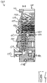
- turbomolecular pump 111 comprises a pump inlet 115 surrounded by an inlet flange 113, to which in a conventional manner, a non-illustrated recipient can be connected.
- the gas from the recipient may be drawn from the recipient via the pump inlet 115 and conveyed through the pump to a pump outlet 117 to which a backing pump, such as a rotary vane pump, may be connected.
- the inlet flange 113 forms according to the orientation of the vacuum pump Fig. 1 the upper end of the housing 119 of the vacuum pump 111.
- the housing 119 comprises a lower part 121, on which an electronics housing 123 is arranged laterally.
- Housed in the electronics housing 123 are electrical and / or electronic components of the vacuum pump 111, eg for operating an electric motor 125 arranged in the vacuum pump.
- a plurality of connections 127 for accessories are provided on the electronics housing 123.
- a data interface 129 for example, according to the RS485 standard, and a power supply terminal 131 on the electronics housing 123 are arranged.
- a flood inlet 133 On the housing 119 of the turbomolecular pump 111, a flood inlet 133, in particular in the form of a flood valve, is provided, via which the vacuum pump 111 can be flooded.
- a sealing gas connection 135, which is also referred to as flushing gas connection is furthermore arranged, via which flushing gas for protecting the electric motor 125 (see, for example, US Pat Fig. 3 ) can be brought before the pumped by the pump gas in the engine compartment 137, in which the electric motor 125 is housed in the vacuum pump 111.
- two coolant connections 139 are further arranged, wherein one of the coolant connections as inlet and the other coolant connection as Outlet for coolant is provided, which can be passed for cooling purposes in the vacuum pump.
- the lower side 141 of the vacuum pump can serve as a base, so that the vacuum pump 111 can be operated standing on the bottom 141.
- the vacuum pump 111 can also be fastened to a recipient via the inlet flange 113 and thus be operated to a certain extent suspended.
- the vacuum pump 111 can be designed so that it can also be put into operation, if it is aligned differently than in Fig. 1 is shown.
- Embodiments of the vacuum pump can also be implemented in which the lower side 141 can not be turned down but can be turned to the side or directed upwards.
- a bearing cap 145 is attached to the bottom 141.
- mounting holes 147 are arranged, via which the pump 111 can be attached, for example, to a support surface.
- a coolant line 148 is shown, in which the coolant introduced and discharged via the coolant connections 139 can circulate.
- the vacuum pump comprises a plurality of process gas pumping stages for conveying the process gas pending at the pump inlet 115 to the pump outlet 117.
- a rotatable relative to a stator 150 rotor 149 is arranged, which has a rotatable about a rotation axis 151 rotor shaft 153.
- Turbomolecular pump 111 includes a plurality of turbomolecular pump stages operatively connected in series with a plurality of rotor disks 155 mounted on rotor shaft 153 and stator disks 157 disposed between rotor disks 155 and housed in housing 119.
- a rotor disk 155 and an adjacent stator disk 157 each form a turbomolecular one pump stage.
- the stator disks 157 are held by spacer rings 159 at a desired axial distance from each other.
- the vacuum pump further comprises Holweck pumping stages which are arranged one inside the other in the radial direction and which are pumpingly connected to one another in series.
- the rotor of the Holweck pump stages comprises a rotor hub 161 arranged on the rotor shaft 153 and two cylinder shell-shaped Holweck rotor sleeves 163, 165 fastened to the rotor hub 161 and oriented coaxially with the rotation axis 151 and nested in the radial direction.
- two cylinder jacket-shaped Holweck stator sleeves 167, 169 are provided, which are also oriented coaxially to the rotation axis 151 and, as seen in the radial direction, are nested one inside the other.
- the pump-active surfaces of the Holweck pump stages are formed by the lateral surfaces, ie by the radial inner and / or outer surfaces, the Holweck rotor sleeves 163, 165 and the Holweck stator sleeves 167, 169.
- the radially inner surface of the outer Holweck stator sleeve 167 faces the radially outer surface of the outer Holweck rotor sleeve 163, forming a radial Holweck gap 171, and forms with it the first Holweck pump stage subsequent to the turbomolecular pumps.
- the radially inner surface of the outer Holweck rotor sleeve 163 faces the radially outer surface of the inner Holweck stator sleeve 169 to form a radial Holweck gap 173 and forms with this is a second Holweck pumping stage.
- the radially inner surface of the inner Holweck stator sleeve 169 faces the radially outer surface of the inner Holweck rotor sleeve 165 to form a radial Holweck gap 175 and forms with this the third Holweck pumping stage.
- a radially extending channel may be provided, via which the radially outer Holweck gap 171 is connected to the middle Holweck gap 173.
- a radially extending channel may be provided, via which the middle Holweck gap 173 is connected to the radially inner Holweck gap 175.
- a connecting channel 179 to the outlet 117 may be provided at the lower end of the radially inner Holweck rotor sleeve 165.
- the above-mentioned pump-active surfaces of the Holweck stator sleeves 163, 165 each have a plurality of Holweck grooves running around the axis of rotation 151 in the axial direction, while the opposite lateral surfaces of the Holweck rotor sleeves 163, 165 are smooth and the gas for operating the Drive vacuum pump 111 in the Holweck grooves.
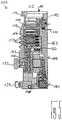
- a roller bearing 181 in the region of the pump outlet 117 and a permanent magnet bearing 183 in the region of the pump inlet 115 are provided.
- an inventive permanent magnet bearing 10 may be provided, as will be described below.
- a conical spray nut 185 with an outer diameter increasing toward the rolling bearing 181 is provided on the rotor shaft 153.
- the spray nut 185 is at least one scraper one Operating equipment in sliding contact.
- the resource storage comprises a plurality of absorbent discs 187 stacked on top of each other and impregnated with a rolling bearing bearing means 181, eg with a lubricant.
- the operating medium is transferred by capillary action of the resource storage on the scraper on the rotating sprayer nut 185 and promoted in the direction of increasing outer diameter of the spray nut 185 to the roller bearing 181 through where the centrifugal force along the spray nut 185 eg fulfills a lubricating function.
- the rolling bearing 181 and the resource storage are enclosed by a trough-shaped insert 189 and the bearing cap 145 in the vacuum pump.
- the permanent magnet bearing 183 includes a rotor-side bearing half 191 and a stator-side bearing half 193, each comprising a ring stack of a plurality of stacked in the axial direction of permanent magnetic rings 195, 197 include.
- the ring magnets 195, 197 are opposed to each other to form a radial bearing gap 199, wherein the rotor-side ring magnets 195 are disposed radially outward and the stator-side ring magnets 197 radially inward.
- the magnetic field present in the bearing gap 199 causes magnetic repulsive forces between the ring magnets 195, 197, which cause a radial bearing of the rotor shaft 153.
- the rotor-side ring magnets 195 are supported by a carrier section 201 of the rotor shaft 153, which surrounds the ring magnets 195 radially on the outside.
- the stator-side ring magnets 197 are supported by a stator-side support portion 203, which extends through the ring magnets 197 and is suspended on radial struts 205 of the housing 119.
- Parallel to the axis of rotation 151, the rotor-side ring magnets 195 are fixed by a lid element 207 coupled to the carrier section 203.
- the stator-side ring magnets 197 are parallel to the axis of rotation 151 in one direction by a fastening ring 209 connected to the carrier section 203 and one connected to the carrier section 203 Fixing ring 211 fixed. Between the fastening ring 211 and the ring magnet 197, a plate spring 213 may also be provided.
- an emergency or catch bearing 215 is provided, which runs empty during normal operation of the vacuum pump 111 without contact and only with an excessive radial deflection of the rotor 149 relative to the stator 150 engages to a radial stop for the rotor 149, since a collision of the rotor-side structures with the stator-side structures is prevented.
- the safety bearing 215 is designed as an unlubricated rolling bearing and forms with the rotor 149 and / or the stator 150 has a radial gap, which causes the safety bearing 215 is disengaged in the normal pumping operation.
- the radial deflection at which the safety bearing 215 engages is sized large enough so that the safety bearing 215 does not engage during normal operation of the vacuum pump, and at the same time small enough so that a collision of the rotor-side structures with the stator-side structures is prevented in all circumstances.
- the vacuum pump 111 includes the electric motor 125 for rotationally driving the rotor 149.
- the armature of the electric motor 125 is formed by the rotor 149 whose rotor shaft 153 extends through the motor stator 217.
- On the extending through the motor stator 217 through portion of the rotor shaft 153 may be arranged radially outside or embedded a permanent magnet arrangement.
- a gap 219 is arranged, which comprises a radial motor gap, via which the motor stator 217 and the permanent magnet arrangement for the transmission of the drive torque can influence magnetically.
- the motor stator 217 is fixed in the housing within the motor space 137 provided for the electric motor 125.
- a sealing gas which is also referred to as purge gas, and which may be, for example, air or nitrogen, enter the engine compartment 137.
- the electric motor 125 can be provided with process gas, e.g. against corrosive fractions of the process gas.
- the engine compartment 137 may also be evacuated via the pump outlet 117, i. In the engine compartment 137, at least approximately, the vacuum pressure caused by the backing pump connected to the pump outlet 117 prevails.
- delimiting wall 221 Between the rotor hub 161 and a motor space 137 delimiting wall 221 may also be a so-called. And per se known labyrinth seal 223 may be provided, in particular to achieve a better seal of the engine compartment 217 against the Holweck pump stages located radially outside.
- Fig. 6 shows a cross-sectional view of a permanent magnet bearing 10 according to the invention according to a first embodiment, which can be used in functional terms instead of the permanent magnet bearing 183 of the turbomolecular pump 111.
- the permanent magnet bearing 10 comprises two successive pairs 12 of hollow cylindrical monolithic permanent magnets 14a, 14b (hereinafter referred to as permanent magnets 14a, 14b) in the direction of a rotation axis D of the permanent magnet bearing 10. It will be appreciated that the permanent magnet bearing 10 may comprise only a pair 12 of permanent magnets 14a, 14b or more than two pairs 12 of permanent magnets 14a, 14b, as indicated by the continuation points continuing in the axial direction.
- the two axially successive permanent magnets 14a can rotor side, ie, attached to the rotor 149 of the turbomolecular pump 111 be.
- the two monolithic permanent magnets 14b are arranged, which may be mounted on the stator 150 of the turbomolecular pump 111 on the stator side.
- the two rotor-side permanent magnets 14a are arranged rotatable relative to the two stator-side permanent magnets 14b with respect to the rotation axis D of the magnetic bearing 10. It is understood that in a corresponding embodiment of the turbomolecular pump 111 and the other way around the stator-side permanent magnets 14b could be arranged radially outside of the rotor-side permanent magnets 14a.
- the rotor-side and stator-side permanent magnets 14a, 14b each have a longitudinal axis L.
- the longitudinal axes L of the rotor-side and stator-side permanent magnets 14a, 14b coincide with the axis of rotation D of the permanent magnet bearing 10.
- each of the permanent magnets 14a, 14b of the permanent magnet bearing 10 has a plurality of axially arranged and at least approximately axially magnetized sections 16, 16 ', the magnetizations of which are aligned alternately opposite to each other, which in Fig. 6 to 8 is indicated by alternately oppositely aligned vector arrows P, P '.
- the axial dimensions of the two end portions 16 'of a respective permanent magnet 14a, 14b differ from the axial dimensions of the portions 16 adjacent to the end portions 16'. Concretely, the axial dimensions of the end portions 16 'are one-half lower than those of FIGS On the other hand, the axial dimensions of all other sections 16 of each permanent magnet 14a, 14b arranged between the two end sections 16 'are at least approximately equal.
- the sections 16, 16 typically have a width of 1 to 10 mm, preferably 2 to 9 mm and particularly preferably 3 to 8 mm.
- pairs of permanent magnets 14a, 14b adjacent end portions 16 'of the successive permanent magnets 14a, 14b each have rectified magnetizations.
- the respective adjacent half end portions 16 ' together have an axial dimension which corresponds to that of one of the adjacent portions 16.
- the advantage of such an arrangement of two pairs 12 of permanent magnets 14a, 14b is that the pairs 12 of permanent magnets 14a, 14b are characterized by both the small stray magnetic field of each individual permanent magnet 14a, 14b and the rectified magnetization of the adjacent end portions 16 '.
- axially successive permanent magnets 14a, 14b particularly well, that is stack with low stacking tolerances, one above the other.
- Fig. 7 shows a permanent magnet bearing according to the invention 10 according to a second embodiment, which differs from the permanent magnet bearing 10 according to the first embodiment in that adjacent end portions 16 'of the successive in the direction of the axis of rotation D of the permanent magnet bearing 10 permanent magnets 14a, 14b each have opposite magnetizations. Since the radial rigidity of a permanent magnet bearing 10 is increased by the number of oppositely magnetized portions per unit length, the arrangement of the pairs 12 of permanent magnets 14a, 14b in the permanent magnet bearing 10 according to the second embodiment has the advantage that it compares to the permanent magnet bearing 10 according to the first embodiment has a higher radial bearing stiffness.
- Fig. 8 shows a cross-sectional view of an arrangement which can be used for producing a monolithic permanent magnet 14 according to the invention from a body 18 of magnetizable material. It is in Fig. 8 only one half of the permanent magnet 14 and the body 18 is shown, wherein one can imagine the other half due to the rotationally symmetrical configuration of the hollow cylindrical permanent magnet 14 and body 18 on the left side of the longitudinal axis L of the permanent magnet 14 and body 18.
- the body 18 may for example consist of iron, a ferrimagnetic ceramic (ferrites) or a magnetizable plastic.
- magnetizable materials comprising rare earth metals are used, such as samarium cobalt (SmCo) or neodymium iron boron (NdFeB).
- the body 18 can be produced by sintering the magnetizable materials.
- the assembly includes an inner coil 20 and an outer coil 22, with the inner coil 20 disposed radially inwardly of the body 18 and the outer coil 22 radially outward of the body.
- Both coils 20, 22 comprise a plurality of axially successive windings 24, wherein the windings 24 of the inner Spool 20 and the windings 24 of the outer coil 22 seen in the direction of the longitudinal axis L of the body 18 are at least approximately arranged at the same height. Based on Fig. 8 It can be seen that in each case a pair of windings 24 arranged at the same height projects axially at axial ends of the body 18.
- the windings 24 have a rectangular conductor cross section with a radial dimension b and an axial dimension h, wherein the windings are separated in the axial direction by the distance d from each other. According to a preferred embodiment, at least one of the windings 24 of the inner coil 20 and / or the outer coil 22 can be controlled separately from the other windings.
- a hollow cylindrical body 18 of magnetizable material is disposed between the inner coil 20 and outer coil 22 such that each pair of equiangularly wound coils 24 axially projects beyond the axial ends of the body 18.
- a voltage is applied to the coils 20, 22 for generating a current flow through the windings 24 such that the resulting current flow through the windings 24 of the inner and outer coils 20, 22 is directed opposite.
- a monolithic hollow-cylindrical permanent magnet 14 is formed from the body 18.
- the permanent magnet 14 can also be produced from a body 18 of magnetizable material designed as a solid cylinder, it being understood that the arrangement of an inner coil 20 in the interior of the magnetizable body 18 is then omitted.
Priority Applications (3)
| Application Number | Priority Date | Filing Date | Title |
|---|---|---|---|
| EP17165109.4A EP3385961B1 (fr) | 2017-04-05 | 2017-04-05 | Aimant permanent monolithique |
| JP2017227380A JP6611780B2 (ja) | 2017-04-05 | 2017-11-28 | モノリス式の永久磁石 |
| CN201711326866.1A CN108691801B (zh) | 2017-04-05 | 2017-12-13 | 一种单片永磁体 |
Applications Claiming Priority (1)
| Application Number | Priority Date | Filing Date | Title |
|---|---|---|---|
| EP17165109.4A EP3385961B1 (fr) | 2017-04-05 | 2017-04-05 | Aimant permanent monolithique |
Publications (2)
| Publication Number | Publication Date |
|---|---|
| EP3385961A1 true EP3385961A1 (fr) | 2018-10-10 |
| EP3385961B1 EP3385961B1 (fr) | 2021-09-01 |
Family
ID=58544740
Family Applications (1)
| Application Number | Title | Priority Date | Filing Date |
|---|---|---|---|
| EP17165109.4A Active EP3385961B1 (fr) | 2017-04-05 | 2017-04-05 | Aimant permanent monolithique |
Country Status (3)
| Country | Link |
|---|---|
| EP (1) | EP3385961B1 (fr) |
| JP (1) | JP6611780B2 (fr) |
| CN (1) | CN108691801B (fr) |
Cited By (2)
| Publication number | Priority date | Publication date | Assignee | Title |
|---|---|---|---|---|
| CN111524681A (zh) * | 2020-03-29 | 2020-08-11 | 至玥腾风科技集团有限公司 | 一种永磁体的充磁方法及高速转子的制造方法 |
| WO2021116637A1 (fr) * | 2019-12-09 | 2021-06-17 | Edwards Limited | Appareil et procédé de magnétisation |
Citations (4)
| Publication number | Priority date | Publication date | Assignee | Title |
|---|---|---|---|---|
| JPH11325075A (ja) * | 1998-05-13 | 1999-11-26 | Sankyo Seiki Mfg Co Ltd | 磁気軸受 |
| JP2002310154A (ja) * | 2001-04-18 | 2002-10-23 | Seiko Epson Corp | 永久磁石磁気回路及び超電導軸受装置 |
| US20140035412A1 (en) * | 2011-05-06 | 2014-02-06 | Edwards Limited | Magnetic Bearing Assembly |
| DE102015113681B3 (de) * | 2015-08-18 | 2016-11-24 | Pfeiffer Vacuum Gmbh | Verfahren zum Reduzieren eines magnetischen Streuvektorfelds einer Vakuumpumpe oder Rotationseinheit sowie Vakuumpumpe und Rotationseinheit |
Family Cites Families (7)
| Publication number | Priority date | Publication date | Assignee | Title |
|---|---|---|---|---|
| CN1148762C (zh) * | 2002-06-14 | 2004-05-05 | 钢铁研究总院 | 多织构整体烧结成型稀土永磁体及制备方法 |
| TW200521350A (en) * | 2003-12-25 | 2005-07-01 | Delta Electronics Inc | Magnetic bearing system |
| DE102014103060B4 (de) * | 2014-03-07 | 2019-01-03 | Pfeiffer Vacuum Gmbh | Verfahren zum Wuchten eines Rotors einer Vakuumpumpe oder eines Rotors einer Rotationseinheit für eine Vakuumpumpe |
| GB201408899D0 (en) * | 2014-05-20 | 2014-07-02 | Edwards Ltd | Magnetic bearing |
| EP3135932B1 (fr) * | 2015-08-24 | 2018-10-31 | Pfeiffer Vacuum Gmbh | Pompe à vide et palier à aimant permanent |
| EP3196471B1 (fr) * | 2016-01-19 | 2023-08-23 | Pfeiffer Vacuum Gmbh | Pompe a vide |
| CN205645431U (zh) * | 2016-05-09 | 2016-10-12 | 深圳市高励磁技术有限公司 | 一种高效可靠无短路电流多极充磁机 |
-
2017
- 2017-04-05 EP EP17165109.4A patent/EP3385961B1/fr active Active
- 2017-11-28 JP JP2017227380A patent/JP6611780B2/ja active Active
- 2017-12-13 CN CN201711326866.1A patent/CN108691801B/zh active Active
Patent Citations (4)
| Publication number | Priority date | Publication date | Assignee | Title |
|---|---|---|---|---|
| JPH11325075A (ja) * | 1998-05-13 | 1999-11-26 | Sankyo Seiki Mfg Co Ltd | 磁気軸受 |
| JP2002310154A (ja) * | 2001-04-18 | 2002-10-23 | Seiko Epson Corp | 永久磁石磁気回路及び超電導軸受装置 |
| US20140035412A1 (en) * | 2011-05-06 | 2014-02-06 | Edwards Limited | Magnetic Bearing Assembly |
| DE102015113681B3 (de) * | 2015-08-18 | 2016-11-24 | Pfeiffer Vacuum Gmbh | Verfahren zum Reduzieren eines magnetischen Streuvektorfelds einer Vakuumpumpe oder Rotationseinheit sowie Vakuumpumpe und Rotationseinheit |
Cited By (3)
| Publication number | Priority date | Publication date | Assignee | Title |
|---|---|---|---|---|
| WO2021116637A1 (fr) * | 2019-12-09 | 2021-06-17 | Edwards Limited | Appareil et procédé de magnétisation |
| CN111524681A (zh) * | 2020-03-29 | 2020-08-11 | 至玥腾风科技集团有限公司 | 一种永磁体的充磁方法及高速转子的制造方法 |
| CN111524681B (zh) * | 2020-03-29 | 2021-07-27 | 靳普 | 一种永磁体的充磁方法及高速转子的制造方法 |
Also Published As
| Publication number | Publication date |
|---|---|
| CN108691801B (zh) | 2021-07-09 |
| JP2018178990A (ja) | 2018-11-15 |
| EP3385961B1 (fr) | 2021-09-01 |
| JP6611780B2 (ja) | 2019-11-27 |
| CN108691801A (zh) | 2018-10-23 |
Similar Documents
| Publication | Publication Date | Title |
|---|---|---|
| DE10022061A1 (de) | Magnetlagerung mit Dämpfung | |
| EP2995820B1 (fr) | Pompe à vide avec rotor de moteur soudé et avec des aimants agencés en forme de v | |
| DE102012216450A1 (de) | Verfahren zum Zentrieren einer Vakuumpumpe oder einer Rotationseinheit für eine Vakuumpumpe | |
| EP3657021B1 (fr) | Pompe à vide | |
| EP0675289A1 (fr) | Pompe à effet visqueux | |
| EP3385961B1 (fr) | Aimant permanent monolithique | |
| EP2508769B1 (fr) | Dispositif de palier magnetique axial doté d'un remplissage en fer augmenté | |
| DE102013220495A1 (de) | Elektrische Maschine | |
| DE102007056116A1 (de) | Permanenterregte elektrische Maschine | |
| DE102012022152A1 (de) | Elektrische Maschine und Rotor für eine elektrische Maschine | |
| EP3196471B1 (fr) | Pompe a vide | |
| DE102021107113A1 (de) | Bürstenloser Motor mit fluiddynamischem Lagersystem | |
| EP3611381B1 (fr) | Procédé de fabrication d'une pompe à vide | |
| EP3244068B1 (fr) | Pompe à vide | |
| DE102013112625A1 (de) | Elektrische Drehmaschine mit Magnetverstärkungsring | |
| EP4038722A1 (fr) | Rotor à excitation permanente à géométrie d'aimant améliorée | |
| EP3693610A1 (fr) | Pompe à vide moléculaire | |
| EP3327293B1 (fr) | Pompe à vide avec une pluralté d'entrées | |
| EP3135932B1 (fr) | Pompe à vide et palier à aimant permanent | |
| EP3447299A1 (fr) | Rondelle de calage | |
| EP3536965A1 (fr) | Pompe à vide dans laquelle le support d'un palier à roulement a une rigidité et/ou un amortissement réglable(s) | |
| EP3767109B1 (fr) | Système à vide | |
| EP3683449B1 (fr) | Palier magnétique et appareil sous vide | |
| EP3561306B1 (fr) | Pompe à vide | |
| EP3628883B1 (fr) | Pompe à vide |
Legal Events
| Date | Code | Title | Description |
|---|---|---|---|
| PUAI | Public reference made under article 153(3) epc to a published international application that has entered the european phase |
Free format text: ORIGINAL CODE: 0009012 |
|
| STAA | Information on the status of an ep patent application or granted ep patent |
Free format text: STATUS: THE APPLICATION HAS BEEN PUBLISHED |
|
| AK | Designated contracting states |
Kind code of ref document: A1 Designated state(s): AL AT BE BG CH CY CZ DE DK EE ES FI FR GB GR HR HU IE IS IT LI LT LU LV MC MK MT NL NO PL PT RO RS SE SI SK SM TR |
|
| AX | Request for extension of the european patent |
Extension state: BA ME |
|
| STAA | Information on the status of an ep patent application or granted ep patent |
Free format text: STATUS: REQUEST FOR EXAMINATION WAS MADE |
|
| 17P | Request for examination filed |
Effective date: 20190226 |
|
| RBV | Designated contracting states (corrected) |
Designated state(s): AL AT BE BG CH CY CZ DE DK EE ES FI FR GB GR HR HU IE IS IT LI LT LU LV MC MK MT NL NO PL PT RO RS SE SI SK SM TR |
|
| STAA | Information on the status of an ep patent application or granted ep patent |
Free format text: STATUS: REQUEST FOR EXAMINATION WAS MADE |
|
| RIC1 | Information provided on ipc code assigned before grant |
Ipc: F04D 19/04 20060101ALI20210212BHEP Ipc: H01F 41/02 20060101ALI20210212BHEP Ipc: F16C 32/04 20060101ALI20210212BHEP Ipc: F04D 29/05 20060101ALI20210212BHEP Ipc: H01F 13/00 20060101ALI20210212BHEP Ipc: H01F 7/02 20060101AFI20210212BHEP |
|
| GRAP | Despatch of communication of intention to grant a patent |
Free format text: ORIGINAL CODE: EPIDOSNIGR1 |
|
| STAA | Information on the status of an ep patent application or granted ep patent |
Free format text: STATUS: GRANT OF PATENT IS INTENDED |
|
| INTG | Intention to grant announced |
Effective date: 20210409 |
|
| GRAS | Grant fee paid |
Free format text: ORIGINAL CODE: EPIDOSNIGR3 |
|
| GRAA | (expected) grant |
Free format text: ORIGINAL CODE: 0009210 |
|
| STAA | Information on the status of an ep patent application or granted ep patent |
Free format text: STATUS: THE PATENT HAS BEEN GRANTED |
|
| AK | Designated contracting states |
Kind code of ref document: B1 Designated state(s): AL AT BE BG CH CY CZ DE DK EE ES FI FR GB GR HR HU IE IS IT LI LT LU LV MC MK MT NL NO PL PT RO RS SE SI SK SM TR |
|
| REG | Reference to a national code |
Ref country code: GB Ref legal event code: FG4D Free format text: NOT ENGLISH |
|
| REG | Reference to a national code |
Ref country code: CH Ref legal event code: EP Ref country code: AT Ref legal event code: REF Ref document number: 1427089 Country of ref document: AT Kind code of ref document: T Effective date: 20210915 |
|
| REG | Reference to a national code |
Ref country code: DE Ref legal event code: R096 Ref document number: 502017011338 Country of ref document: DE |
|
| REG | Reference to a national code |
Ref country code: IE Ref legal event code: FG4D Free format text: LANGUAGE OF EP DOCUMENT: GERMAN |
|
| REG | Reference to a national code |
Ref country code: LT Ref legal event code: MG9D |
|
| REG | Reference to a national code |
Ref country code: NL Ref legal event code: MP Effective date: 20210901 |
|
| PG25 | Lapsed in a contracting state [announced via postgrant information from national office to epo] |
Ref country code: SE Free format text: LAPSE BECAUSE OF FAILURE TO SUBMIT A TRANSLATION OF THE DESCRIPTION OR TO PAY THE FEE WITHIN THE PRESCRIBED TIME-LIMIT Effective date: 20210901 Ref country code: RS Free format text: LAPSE BECAUSE OF FAILURE TO SUBMIT A TRANSLATION OF THE DESCRIPTION OR TO PAY THE FEE WITHIN THE PRESCRIBED TIME-LIMIT Effective date: 20210901 Ref country code: NO Free format text: LAPSE BECAUSE OF FAILURE TO SUBMIT A TRANSLATION OF THE DESCRIPTION OR TO PAY THE FEE WITHIN THE PRESCRIBED TIME-LIMIT Effective date: 20211201 Ref country code: ES Free format text: LAPSE BECAUSE OF FAILURE TO SUBMIT A TRANSLATION OF THE DESCRIPTION OR TO PAY THE FEE WITHIN THE PRESCRIBED TIME-LIMIT Effective date: 20210901 Ref country code: FI Free format text: LAPSE BECAUSE OF FAILURE TO SUBMIT A TRANSLATION OF THE DESCRIPTION OR TO PAY THE FEE WITHIN THE PRESCRIBED TIME-LIMIT Effective date: 20210901 Ref country code: HR Free format text: LAPSE BECAUSE OF FAILURE TO SUBMIT A TRANSLATION OF THE DESCRIPTION OR TO PAY THE FEE WITHIN THE PRESCRIBED TIME-LIMIT Effective date: 20210901 Ref country code: BG Free format text: LAPSE BECAUSE OF FAILURE TO SUBMIT A TRANSLATION OF THE DESCRIPTION OR TO PAY THE FEE WITHIN THE PRESCRIBED TIME-LIMIT Effective date: 20211201 Ref country code: LT Free format text: LAPSE BECAUSE OF FAILURE TO SUBMIT A TRANSLATION OF THE DESCRIPTION OR TO PAY THE FEE WITHIN THE PRESCRIBED TIME-LIMIT Effective date: 20210901 |
|
| PG25 | Lapsed in a contracting state [announced via postgrant information from national office to epo] |
Ref country code: PL Free format text: LAPSE BECAUSE OF FAILURE TO SUBMIT A TRANSLATION OF THE DESCRIPTION OR TO PAY THE FEE WITHIN THE PRESCRIBED TIME-LIMIT Effective date: 20210901 Ref country code: LV Free format text: LAPSE BECAUSE OF FAILURE TO SUBMIT A TRANSLATION OF THE DESCRIPTION OR TO PAY THE FEE WITHIN THE PRESCRIBED TIME-LIMIT Effective date: 20210901 Ref country code: GR Free format text: LAPSE BECAUSE OF FAILURE TO SUBMIT A TRANSLATION OF THE DESCRIPTION OR TO PAY THE FEE WITHIN THE PRESCRIBED TIME-LIMIT Effective date: 20211202 |
|
| PG25 | Lapsed in a contracting state [announced via postgrant information from national office to epo] |
Ref country code: IS Free format text: LAPSE BECAUSE OF FAILURE TO SUBMIT A TRANSLATION OF THE DESCRIPTION OR TO PAY THE FEE WITHIN THE PRESCRIBED TIME-LIMIT Effective date: 20220101 Ref country code: SM Free format text: LAPSE BECAUSE OF FAILURE TO SUBMIT A TRANSLATION OF THE DESCRIPTION OR TO PAY THE FEE WITHIN THE PRESCRIBED TIME-LIMIT Effective date: 20210901 Ref country code: SK Free format text: LAPSE BECAUSE OF FAILURE TO SUBMIT A TRANSLATION OF THE DESCRIPTION OR TO PAY THE FEE WITHIN THE PRESCRIBED TIME-LIMIT Effective date: 20210901 Ref country code: RO Free format text: LAPSE BECAUSE OF FAILURE TO SUBMIT A TRANSLATION OF THE DESCRIPTION OR TO PAY THE FEE WITHIN THE PRESCRIBED TIME-LIMIT Effective date: 20210901 Ref country code: PT Free format text: LAPSE BECAUSE OF FAILURE TO SUBMIT A TRANSLATION OF THE DESCRIPTION OR TO PAY THE FEE WITHIN THE PRESCRIBED TIME-LIMIT Effective date: 20220103 Ref country code: NL Free format text: LAPSE BECAUSE OF FAILURE TO SUBMIT A TRANSLATION OF THE DESCRIPTION OR TO PAY THE FEE WITHIN THE PRESCRIBED TIME-LIMIT Effective date: 20210901 Ref country code: EE Free format text: LAPSE BECAUSE OF FAILURE TO SUBMIT A TRANSLATION OF THE DESCRIPTION OR TO PAY THE FEE WITHIN THE PRESCRIBED TIME-LIMIT Effective date: 20210901 Ref country code: AL Free format text: LAPSE BECAUSE OF FAILURE TO SUBMIT A TRANSLATION OF THE DESCRIPTION OR TO PAY THE FEE WITHIN THE PRESCRIBED TIME-LIMIT Effective date: 20210901 |
|
| REG | Reference to a national code |
Ref country code: DE Ref legal event code: R097 Ref document number: 502017011338 Country of ref document: DE |
|
| PLBE | No opposition filed within time limit |
Free format text: ORIGINAL CODE: 0009261 |
|
| STAA | Information on the status of an ep patent application or granted ep patent |
Free format text: STATUS: NO OPPOSITION FILED WITHIN TIME LIMIT |
|
| PG25 | Lapsed in a contracting state [announced via postgrant information from national office to epo] |
Ref country code: DK Free format text: LAPSE BECAUSE OF FAILURE TO SUBMIT A TRANSLATION OF THE DESCRIPTION OR TO PAY THE FEE WITHIN THE PRESCRIBED TIME-LIMIT Effective date: 20210901 |
|
| 26N | No opposition filed |
Effective date: 20220602 |
|
| PG25 | Lapsed in a contracting state [announced via postgrant information from national office to epo] |
Ref country code: SI Free format text: LAPSE BECAUSE OF FAILURE TO SUBMIT A TRANSLATION OF THE DESCRIPTION OR TO PAY THE FEE WITHIN THE PRESCRIBED TIME-LIMIT Effective date: 20210901 |
|
| REG | Reference to a national code |
Ref country code: CH Ref legal event code: PL |
|
| REG | Reference to a national code |
Ref country code: BE Ref legal event code: MM Effective date: 20220430 |
|
| PG25 | Lapsed in a contracting state [announced via postgrant information from national office to epo] |
Ref country code: MC Free format text: LAPSE BECAUSE OF FAILURE TO SUBMIT A TRANSLATION OF THE DESCRIPTION OR TO PAY THE FEE WITHIN THE PRESCRIBED TIME-LIMIT Effective date: 20210901 Ref country code: LU Free format text: LAPSE BECAUSE OF NON-PAYMENT OF DUE FEES Effective date: 20220405 Ref country code: LI Free format text: LAPSE BECAUSE OF NON-PAYMENT OF DUE FEES Effective date: 20220430 Ref country code: FR Free format text: LAPSE BECAUSE OF NON-PAYMENT OF DUE FEES Effective date: 20220430 Ref country code: CH Free format text: LAPSE BECAUSE OF NON-PAYMENT OF DUE FEES Effective date: 20220430 |
|
| PG25 | Lapsed in a contracting state [announced via postgrant information from national office to epo] |
Ref country code: BE Free format text: LAPSE BECAUSE OF NON-PAYMENT OF DUE FEES Effective date: 20220430 |
|
| PG25 | Lapsed in a contracting state [announced via postgrant information from national office to epo] |
Ref country code: IE Free format text: LAPSE BECAUSE OF NON-PAYMENT OF DUE FEES Effective date: 20220405 |
|
| PGFP | Annual fee paid to national office [announced via postgrant information from national office to epo] |
Ref country code: CZ Payment date: 20230328 Year of fee payment: 7 |
|
| REG | Reference to a national code |
Ref country code: AT Ref legal event code: MM01 Ref document number: 1427089 Country of ref document: AT Kind code of ref document: T Effective date: 20220405 |
|
| PG25 | Lapsed in a contracting state [announced via postgrant information from national office to epo] |
Ref country code: AT Free format text: LAPSE BECAUSE OF NON-PAYMENT OF DUE FEES Effective date: 20220405 |
|
| PGFP | Annual fee paid to national office [announced via postgrant information from national office to epo] |
Ref country code: IT Payment date: 20230426 Year of fee payment: 7 Ref country code: DE Payment date: 20230627 Year of fee payment: 7 |
|
| PGFP | Annual fee paid to national office [announced via postgrant information from national office to epo] |
Ref country code: GB Payment date: 20230419 Year of fee payment: 7 |
|
| PG25 | Lapsed in a contracting state [announced via postgrant information from national office to epo] |
Ref country code: HU Free format text: LAPSE BECAUSE OF FAILURE TO SUBMIT A TRANSLATION OF THE DESCRIPTION OR TO PAY THE FEE WITHIN THE PRESCRIBED TIME-LIMIT; INVALID AB INITIO Effective date: 20170405 |
|
| PG25 | Lapsed in a contracting state [announced via postgrant information from national office to epo] |
Ref country code: MK Free format text: LAPSE BECAUSE OF FAILURE TO SUBMIT A TRANSLATION OF THE DESCRIPTION OR TO PAY THE FEE WITHIN THE PRESCRIBED TIME-LIMIT Effective date: 20210901 Ref country code: CY Free format text: LAPSE BECAUSE OF FAILURE TO SUBMIT A TRANSLATION OF THE DESCRIPTION OR TO PAY THE FEE WITHIN THE PRESCRIBED TIME-LIMIT Effective date: 20210901 |