EP3385961B1 - Aimant permanent monolithique - Google Patents
Aimant permanent monolithique Download PDFInfo
- Publication number
- EP3385961B1 EP3385961B1 EP17165109.4A EP17165109A EP3385961B1 EP 3385961 B1 EP3385961 B1 EP 3385961B1 EP 17165109 A EP17165109 A EP 17165109A EP 3385961 B1 EP3385961 B1 EP 3385961B1
- Authority
- EP
- European Patent Office
- Prior art keywords
- permanent magnet
- monolithic
- accordance
- windings
- coil
- Prior art date
- Legal status (The legal status is an assumption and is not a legal conclusion. Google has not performed a legal analysis and makes no representation as to the accuracy of the status listed.)
- Active
Links
Images


Classifications
-
- H—ELECTRICITY
- H01—ELECTRIC ELEMENTS
- H01F—MAGNETS; INDUCTANCES; TRANSFORMERS; SELECTION OF MATERIALS FOR THEIR MAGNETIC PROPERTIES
- H01F7/00—Magnets
- H01F7/02—Permanent magnets [PM]
- H01F7/0205—Magnetic circuits with PM in general
- H01F7/021—Construction of PM
-
- F—MECHANICAL ENGINEERING; LIGHTING; HEATING; WEAPONS; BLASTING
- F04—POSITIVE - DISPLACEMENT MACHINES FOR LIQUIDS; PUMPS FOR LIQUIDS OR ELASTIC FLUIDS
- F04D—NON-POSITIVE-DISPLACEMENT PUMPS
- F04D29/00—Details, component parts, or accessories
- F04D29/05—Shafts or bearings, or assemblies thereof, specially adapted for elastic fluid pumps
- F04D29/056—Bearings
- F04D29/058—Bearings magnetic; electromagnetic
-
- F—MECHANICAL ENGINEERING; LIGHTING; HEATING; WEAPONS; BLASTING
- F04—POSITIVE - DISPLACEMENT MACHINES FOR LIQUIDS; PUMPS FOR LIQUIDS OR ELASTIC FLUIDS
- F04D—NON-POSITIVE-DISPLACEMENT PUMPS
- F04D19/00—Axial-flow pumps
- F04D19/02—Multi-stage pumps
- F04D19/04—Multi-stage pumps specially adapted to the production of a high vacuum, e.g. molecular pumps
- F04D19/048—Multi-stage pumps specially adapted to the production of a high vacuum, e.g. molecular pumps comprising magnetic bearings
-
- F—MECHANICAL ENGINEERING; LIGHTING; HEATING; WEAPONS; BLASTING
- F16—ENGINEERING ELEMENTS AND UNITS; GENERAL MEASURES FOR PRODUCING AND MAINTAINING EFFECTIVE FUNCTIONING OF MACHINES OR INSTALLATIONS; THERMAL INSULATION IN GENERAL
- F16C—SHAFTS; FLEXIBLE SHAFTS; ELEMENTS OR CRANKSHAFT MECHANISMS; ROTARY BODIES OTHER THAN GEARING ELEMENTS; BEARINGS
- F16C32/00—Bearings not otherwise provided for
- F16C32/04—Bearings not otherwise provided for using magnetic or electric supporting means
- F16C32/0406—Magnetic bearings
- F16C32/0408—Passive magnetic bearings
- F16C32/0423—Passive magnetic bearings with permanent magnets on both parts repelling each other
- F16C32/0425—Passive magnetic bearings with permanent magnets on both parts repelling each other for radial load mainly
-
- H—ELECTRICITY
- H01—ELECTRIC ELEMENTS
- H01F—MAGNETS; INDUCTANCES; TRANSFORMERS; SELECTION OF MATERIALS FOR THEIR MAGNETIC PROPERTIES
- H01F13/00—Apparatus or processes for magnetising or demagnetising
- H01F13/003—Methods and devices for magnetising permanent magnets
-
- H—ELECTRICITY
- H01—ELECTRIC ELEMENTS
- H01F—MAGNETS; INDUCTANCES; TRANSFORMERS; SELECTION OF MATERIALS FOR THEIR MAGNETIC PROPERTIES
- H01F41/00—Apparatus or processes specially adapted for manufacturing or assembling magnets, inductances or transformers; Apparatus or processes specially adapted for manufacturing materials characterised by their magnetic properties
- H01F41/02—Apparatus or processes specially adapted for manufacturing or assembling magnets, inductances or transformers; Apparatus or processes specially adapted for manufacturing materials characterised by their magnetic properties for manufacturing cores, coils, or magnets
- H01F41/0253—Apparatus or processes specially adapted for manufacturing or assembling magnets, inductances or transformers; Apparatus or processes specially adapted for manufacturing materials characterised by their magnetic properties for manufacturing cores, coils, or magnets for manufacturing permanent magnets
-
- F—MECHANICAL ENGINEERING; LIGHTING; HEATING; WEAPONS; BLASTING
- F16—ENGINEERING ELEMENTS AND UNITS; GENERAL MEASURES FOR PRODUCING AND MAINTAINING EFFECTIVE FUNCTIONING OF MACHINES OR INSTALLATIONS; THERMAL INSULATION IN GENERAL
- F16C—SHAFTS; FLEXIBLE SHAFTS; ELEMENTS OR CRANKSHAFT MECHANISMS; ROTARY BODIES OTHER THAN GEARING ELEMENTS; BEARINGS
- F16C19/00—Bearings with rolling contact, for exclusively rotary movement
- F16C19/02—Bearings with rolling contact, for exclusively rotary movement with bearing balls essentially of the same size in one or more circular rows
- F16C19/04—Bearings with rolling contact, for exclusively rotary movement with bearing balls essentially of the same size in one or more circular rows for radial load mainly
- F16C19/06—Bearings with rolling contact, for exclusively rotary movement with bearing balls essentially of the same size in one or more circular rows for radial load mainly with a single row or balls
-
- F—MECHANICAL ENGINEERING; LIGHTING; HEATING; WEAPONS; BLASTING
- F16—ENGINEERING ELEMENTS AND UNITS; GENERAL MEASURES FOR PRODUCING AND MAINTAINING EFFECTIVE FUNCTIONING OF MACHINES OR INSTALLATIONS; THERMAL INSULATION IN GENERAL
- F16C—SHAFTS; FLEXIBLE SHAFTS; ELEMENTS OR CRANKSHAFT MECHANISMS; ROTARY BODIES OTHER THAN GEARING ELEMENTS; BEARINGS
- F16C2360/00—Engines or pumps
- F16C2360/44—Centrifugal pumps
- F16C2360/45—Turbo-molecular pumps
-
- F—MECHANICAL ENGINEERING; LIGHTING; HEATING; WEAPONS; BLASTING
- F16—ENGINEERING ELEMENTS AND UNITS; GENERAL MEASURES FOR PRODUCING AND MAINTAINING EFFECTIVE FUNCTIONING OF MACHINES OR INSTALLATIONS; THERMAL INSULATION IN GENERAL
- F16C—SHAFTS; FLEXIBLE SHAFTS; ELEMENTS OR CRANKSHAFT MECHANISMS; ROTARY BODIES OTHER THAN GEARING ELEMENTS; BEARINGS
- F16C32/00—Bearings not otherwise provided for
- F16C32/04—Bearings not otherwise provided for using magnetic or electric supporting means
- F16C32/0402—Bearings not otherwise provided for using magnetic or electric supporting means combined with other supporting means, e.g. hybrid bearings with both magnetic and fluid supporting means
-
- F—MECHANICAL ENGINEERING; LIGHTING; HEATING; WEAPONS; BLASTING
- F16—ENGINEERING ELEMENTS AND UNITS; GENERAL MEASURES FOR PRODUCING AND MAINTAINING EFFECTIVE FUNCTIONING OF MACHINES OR INSTALLATIONS; THERMAL INSULATION IN GENERAL
- F16C—SHAFTS; FLEXIBLE SHAFTS; ELEMENTS OR CRANKSHAFT MECHANISMS; ROTARY BODIES OTHER THAN GEARING ELEMENTS; BEARINGS
- F16C39/00—Relieving load on bearings
- F16C39/02—Relieving load on bearings using mechanical means
Definitions
- the present invention relates to a monolithic permanent magnet, in particular for a permanent magnet bearing of a vacuum pump, with a longitudinal axis and a plurality of sections arranged along this axis and at least approximately axially magnetized, the magnetizations of which are alternately aligned opposite to one another.
- Monolithic permanent magnets are known in principle and are used, for example, in vacuum pumps, in particular in turbo-molecular pumps, for the lubricant-free mounting of a rotor that is rotatable with respect to a stator.
- both the stator and the rotor each have at least one monolithic permanent magnet, which together form a permanent magnetic bearing.
- magnetic ring JP 2002 310 154 A there is a stack of individual magnets from the magnetic ring JP 2002 310 154 A known, wherein the magnetic ring stack comprises two terminal magnets, each of which has a smaller axial dimension than magnets arranged between them.
- magnetic ring stacks are in the JP H11 325 075 A , US 2014/035412 A1 and DE 10 2015 113 681 B3 disclosed. the end EP3146222B1 a monolithic permanent magnet is known.
- the stray magnetic field can affect highly sensitive applications, for example by deflecting an electron beam from an electron microscope as a result of the Lorentz force, which causes imaging errors can be evoked.
- the magnetic stray field can also influence the magnetization of a highly sensitive magnetic thin film deposited under vacuum. There is therefore a need for monolithic permanent magnets with a low magnetic stray field.
- the object is achieved by a monolithic permanent magnet with the features of claim 1 and in particular in that the axial dimension and / or the magnetization of at least one magnetized section and the axial dimension and / or the magnetization of at least one other magnetized section differ.
- the invention is based on the knowledge that the magnetic stray field of a monolithic permanent magnet is reduced if the axial dimension and / or magnetization of at least one magnetized section differs or differ from the axial dimension and / or magnetization of at least one other magnetized section.
- the reduction in the stray magnetic field has the advantage that the monolithic permanent magnet can be used in applications where a low stray magnetic field is essential, such as in the bearings of vacuum pumps that are used to evacuate electron microscopes.
- the use of the monolithic permanent magnet according to the invention is not limited to use in vacuum pumps. It is also conceivable that a monolithic permanent magnet according to the invention can be used wherever low magnetic stray fields are desirable, such as in audio amplifiers.
- Magnetization of a magnetized section is understood here to mean the magnetic remanence which the magnetized section retains after the external magnetic field required for magnetization, ie to achieve magnetization, has been deactivated.
- a monolithic permanent magnet unlike a magnet stack formed by several individual magnets stacked on top of one another, is a magnet made from one piece.
- the individual sections of the monolithic permanent magnet can therefore not be visually recognized as such, but only differ with regard to their respective magnetization orientation.
- Each magnetized section has a magnetic north and south pole, with the orientation of the magnetization being defined by convention by a vector arrow starting in the interior of the magnetized section from the south pole and ending at the north pole.
- the respective magnetized sections of the monolithic permanent magnet are magnetized at least approximately in the axial direction. This means that the magnetization orientation of a magnetized section is oriented at least approximately parallel to the longitudinal axis of the monolithic permanent magnet.
- the monolithic permanent magnet is preferably made of a magnetizable material such as iron, a ferrimagnetic ceramic (ferrit) or a magnetizable plastic. It is also possible with preference to use magnetizable materials which comprise rare earth metals, such as, for example, samarium cobalt (SmCo) or neodymium iron boron (NdFeB). The magnetizable materials can be joined, for example, by a sintering process.
- a monolithic permanent magnet can have an overall length between 15 and 25 mm, preferably between 17 and 23 mm and particularly preferably between 19 and 21 mm. The width of a section can be between 1 and 10 mm, preferably between 2 and 9 mm and particularly preferably between 3 and 8 mm.
- the axial dimension and / or magnetization of the at least one magnetized section can be smaller, in particular by half less, than the axial dimension and / or magnetization of the other magnetized section.
- a particularly strong reduction in the magnetic stray field can be achieved if the axial dimension and / or magnetization of one or each end section and the axial dimension and / or magnetization of a magnetized section adjacent to the or each end section differ.
- the axial dimension and / or magnetization of the or each end section is or are at least approximately half less than that of the adjacent section. It goes without saying that the axial dimension and / or magnetization of the or each end section can in principle also be smaller by a fraction other than half than that of the adjacent section, such as, for example, by a third, two thirds, a quarter or any other fractions.
- at least one magnetized section has a larger axial dimension and / or stronger magnetization than that of an adjacent section.
- the axial dimensions and / or magnetizations of all sections of the monolithic permanent magnet arranged between two end sections are preferred at least approximately the same size. This includes that one end section has at least approximately the same axial dimension and / or magnetization as all other sections arranged between the end sections.
- the axial dimensions and / or magnetizations of the magnetized sections can change from section to section, preferably increase, in particular increase successively.
- all magnetized sections of the monolithic permanent magnet are magnetically saturated, ie the magnetized sections have at least approximately a maximum achievable saturation value of the magnetization.
- the or each magnetized end section can also be magnetically saturated, in particular if the axial dimension of the or each end section is smaller than that of the adjacent section.
- all magnetized sections of the monolithic permanent magnet have at least approximately the same axial dimensions, and at least one magnetized end section is magnetized differently, in particular less, than a section adjacent to the at least one end section.
- at least one magnetized end section has both a different, in particular a smaller, axial one Dimension as well as a different, in particular lower, magnetization than a magnetized section adjacent to the at least one end section.
- the monolithic permanent magnet is designed as a hollow cylinder. It goes without saying that the monolithic permanent magnet can also be designed as a solid cylinder. In principle, the monolithic permanent magnet can also have any other prismatic shape, e.g. that of a cuboid.
- the invention is also directed to a permanent magnet bearing, in particular for a vacuum pump, with a pair of monolithic permanent magnets, one permanent magnet being rotatably mounted relative to the other permanent magnet about an axis of rotation at least approximately parallel to the longitudinal axes of the permanent magnets.
- One of the permanent magnets is arranged radially inside the other permanent magnet in such a way that radially adjacent sections of the outer and inner monolithic permanent magnets are at least approximately at the same height as viewed in the direction of the axis of rotation.
- the magnetizations of the radially adjacent sections of the outer and inner monolithic permanent magnets are at least approximately in the same direction.
- the longitudinal axes of the permanent magnets and the axis of rotation of the permanent magnet bearing are preferably aligned parallel to one another.
- the longitudinal axes of the permanent magnets and the axis of rotation of the permanent magnet bearing can coincide.
- the radial rigidity of the permanent magnet bearing can be significantly increased if the permanent magnet bearing is formed from at least two successive pairs of monolithic permanent magnets viewed in the direction of the axis of rotation and adjoining sections of the successive permanent magnets each have opposite magnetizations.
- the permanent magnetic bearing can comprise both exclusively monolithic permanent magnets and a combination of one or more monolithic permanent magnets and one or more individual magnets or a combination of several individual magnets, at least one of which differs from the rest in terms of axial dimensions and / or magnetization.
- the permanent magnets of the or each pair of permanent magnets are advantageously designed as hollow cylinders. If the permanent magnet bearing also includes individual magnets, then these can be designed as ring magnets.
- the invention also relates to a vacuum pump, in particular a turbo molecular pump, with a rotor and a stator and a permanent magnet bearing, one monolithic permanent magnet being arranged on the rotor side and the other monolithic permanent magnet being arranged on the stator side. It is irrelevant whether the rotor is arranged inside the stator or, conversely, the stator is arranged inside the rotor.
- the invention also relates to a method for producing a monolithic permanent magnet.
- the method comprises the following steps: providing a body made of magnetizable material which defines a longitudinal axis, arranging the body in the interior of an outer coil surrounding the body with a plurality of axially successive windings and applying a voltage to the coil to generate a current flow through the windings in such a way, that the resulting current flow in axially successive windings is opposite in order to form a monolithic permanent magnet from the body by the magnetic field caused thereby.
- the method can additionally include the steps: providing a hollow cylindrical body made of magnetizable material, which defines a longitudinal axis, additionally arranging an inner coil with several axially successive windings inside the body, whereby the windings of the inner coil and the outer coil are arranged at least approximately at the same height as seen in the direction of the longitudinal axis of the body and applying a voltage to generate a current flow through the windings of the inner and outer coil in such a way that the resulting current flow through the windings of the inner and outer coil is directed in opposite directions to form a monolithic hollow cylindrical permanent magnet from the body by the magnetic field created between the inner and outer windings.
- one coil i.e. either the inner coil or the outer coil, is sufficient to produce a hollow cylindrical monolithic permanent magnet.
- the inner and outer coils are formed by a single coil with opposing windings, the inner and outer windings each being arranged at a common height.
- the windings advantageously have a rectangular, in particular square, conductor cross-section. However, it cannot be ruled out that the windings can also have a different conductor cross-section, such as a round or polygonal conductor cross-section, for example.
- a monolithic permanent magnet with at least one magnetized section the axial dimension of which differs from the axial dimension of at least one other magnetized section
- the axial dimension of at least one winding of a coil differs from the axial dimension of at least one other winding of the coil differs. If, additionally or alternatively, the magnetization of at least one magnetized section is to differ from the magnetization of another magnetized section, at least one winding of a coil can generate a magnetic field when a voltage is applied through the resulting current flow, which differs from the magnetic field of another winding of the coil .
- a monolithic permanent magnet with at least one magnetized end section which has a smaller axial dimension and / or magnetization than that of the section adjacent to the end section, can be produced in that all windings of a coil have at least approximately the same axial dimensions and at least one winding over one protrudes from the axial end of the body.
- the winding does not protrude axially at the axial end of the body, but rather one has a smaller conductor cross-section, in particular a smaller axial dimension, so that the inner and / or outer coil and the body are aligned flush with one another.
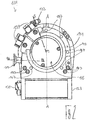
- the turbo molecular pump 111 shown comprises a pump inlet 115 which is surrounded by an inlet flange 113 and to which a recipient (not shown) can be connected in a manner known per se.
- the gas from the recipient can be sucked out of the recipient via the pump inlet 115 and conveyed through the pump to a pump outlet 117 to which a backing pump, such as a rotary vane pump, can be connected.
- the inlet flange 113 forms according to FIG Fig. 1 the upper end of the housing 119 of the vacuum pump 111.
- the housing 119 comprises a lower part 121 on which an electronics housing 123 is arranged laterally. Electrical and / or electronic components of the vacuum pump 111 are accommodated in the electronics housing 123, for example for operating an electric motor 125 arranged in the vacuum pump. A plurality of connections 127 for accessories are provided on the electronics housing 123.
- a data interface 129 for example in accordance with the RS485 standard, and a power supply connection 131 are arranged on the electronics housing 123.
- a flood inlet 133 in particular in the form of a flood valve, is provided on the housing 119 of the turbo molecular pump 111, via which the vacuum pump 111 can be flooded.
- a sealing gas connection 135, which is also referred to as a purging gas connection via which purging gas is used to protect the electric motor 125 (see e.g. Fig. 3 ) can be brought into the engine compartment 137, in which the electric motor 125 in the vacuum pump 111 is accommodated, before the gas conveyed by the pump.
- Two coolant connections 139 are also arranged in the lower part 121, one of the coolant connections as an inlet and the other coolant connection as Outlet for coolant is provided, which can be passed into the vacuum pump for cooling purposes.
- the lower side 141 of the vacuum pump can serve as a standing surface, so that the vacuum pump 111 can be operated standing on the lower side 141.
- the vacuum pump 111 can, however, also be attached to a recipient via the inlet flange 113 and can thus be operated in a suspended manner, as it were.
- the vacuum pump 111 can be designed in such a way that it can also be put into operation when it is oriented in a different way than in FIG Fig. 1 is shown.
- Embodiments of the vacuum pump can also be implemented in which the underside 141 cannot be arranged facing downwards, but facing to the side or facing upwards.
- various screws 143 are also arranged by means of which components of the vacuum pump not specified here are attached to one another.
- a bearing cap 145 is attached to the underside 141.
- Fastening bores 147 are also arranged on the underside 141, via which the pump 111 can be fastened to a support surface, for example.
- a coolant line 148 is shown, in which the coolant introduced and discharged via the coolant connections 139 can circulate.
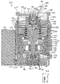
- the vacuum pump comprises several process gas pump stages for conveying the process gas present at the pump inlet 115 to the pump outlet 117.
- a rotor 149 which is rotatable with respect to a stator 150 and has a rotor shaft 153 which can rotate about an axis of rotation 151 is arranged in the housing 119.
- the turbo-molecular pump 111 comprises several turbo-molecular pump stages connected in series with one another with several radial rotor disks 155 fastened to the rotor shaft 153 and stator disks 157 arranged between the rotor disks 155 and fixed in the housing 119.
- a rotor disk 155 and an adjacent stator disk 157 each form a turbomolecular one Pumping stage.
- the stator disks 157 are held at a desired axial distance from one another by spacer rings 159.
- the vacuum pump also comprises Holweck pump stages which are arranged one inside the other in the radial direction and are connected in series with one another for effective pumping.
- the rotor of the Holweck pump stages comprises a rotor hub 161 arranged on the rotor shaft 153 and two cylinder-jacket-shaped Holweck rotor sleeves 163, 165 which are attached to the rotor hub 161 and carried by the latter, which are oriented coaxially to the axis of rotation 151 and nested in one another in the radial direction.
- two cylinder jacket-shaped Holweck stator sleeves 167, 169 are provided, which are also oriented coaxially to the axis of rotation 151 and, viewed in the radial direction, are nested inside one another.
- the active pumping surfaces of the Holweck pump stages are formed by the jacket surfaces, that is to say by the radial inner and / or outer surfaces, of the Holweck rotor sleeves 163, 165 and the Holweck stator sleeves 167, 169.
- the radial inner surface of the outer Holweck stator sleeve 167 lies opposite the radial outer surface of the outer Holweck rotor sleeve 163 with the formation of a radial Holweck gap 171 and with this forms the first Holweck pump stage following the turbomolecular pumps.
- the radial inner surface of the outer Holweck rotor sleeve 163 faces the radial outer surface of the inner Holweck stator sleeve 169 with the formation of a radial Holweck gap 173 and forms with it this a second Holweck pumping stage.
- the radial inner surface of the inner Holweck stator sleeve 169 lies opposite the radial outer surface of the inner Holweck rotor sleeve 165 with the formation of a radial Holweck gap 175 and with this forms the third Holweck pumping stage.
- a radially running channel can be provided, via which the radially outer Holweck gap 171 is connected to the central Holweck gap 173.
- a radially running channel can be provided at the upper end of the inner Holweck stator sleeve 169, via which the middle Holweck gap 173 is connected to the radially inner Holweck gap 175.
- a connecting channel 179 to the outlet 117 can also be provided at the lower end of the radially inner Holweck rotor sleeve 165.
- the aforementioned pump-active surfaces of the Holweck stator sleeves 163, 165 each have a plurality of Holweck grooves running spirally around the axis of rotation 151 in the axial direction, while the opposite lateral surfaces of the Holweck rotor sleeves 163, 165 are smooth and the gas for operating the Drive vacuum pump 111 in the Holweck grooves.
- a roller bearing 181 is provided in the area of the pump outlet 117 and a permanent magnetic bearing 183 in the area of the pump inlet 115.
- a permanent magnetic bearing 10 according to the invention can also be provided, as will be described below.
- a conical injection molded nut 185 is provided on the rotor shaft 153 with an outer diameter that increases towards the roller bearing 181.
- the injection nut 185 stands with at least one wiper one Resource storage in sliding contact.
- the operating medium reservoir comprises several absorbent disks 187 stacked on top of one another, which are impregnated with an operating medium for the roller bearing 181, for example with a lubricant.
- the operating medium is transferred by capillary action from the operating medium reservoir via the scraper to the rotating injection nut 185 and, as a result of the centrifugal force, is conveyed along the injection nut 185 in the direction of the increasing outer diameter of the injection nut 185 to the roller bearing 181, where it eg fulfills a lubricating function.
- the roller bearing 181 and the operating medium store are enclosed in the vacuum pump by a trough-shaped insert 189 and the bearing cover 145.
- the permanent magnetic bearing 183 comprises a rotor-side bearing half 191 and a stator-side bearing half 193, each of which comprises a ring stack of several permanent magnetic rings 195, 197 stacked on top of one another in the axial direction.
- the ring magnets 195, 197 are opposite one another with the formation of a radial bearing gap 199, the rotor-side ring magnets 195 being arranged radially on the outside and the stator-side ring magnets 197 being arranged radially on the inside.
- the magnetic field present in the bearing gap 199 causes magnetic repulsive forces between the ring magnets 195, 197, which cause the rotor shaft 153 to be supported radially.
- the rotor-side ring magnets 195 are carried by a carrier section 201 of the rotor shaft 153 which surrounds the ring magnets 195 radially on the outside.
- the stator-side ring magnets 197 are carried by a stator-side support section 203 which extends through the ring magnets 197 and is suspended from radial struts 205 of the housing 119.
- the ring magnets 195 on the rotor side are fixed parallel to the axis of rotation 151 by a cover element 207 coupled to the carrier section 203.
- the stator-side ring magnets 197 are parallel to the axis of rotation 151 in one direction by a fastening ring 209 connected to the carrier section 203 and one connected to the carrier section 203 Fixing ring 211 set.
- a plate spring 213 can also be provided between the fastening ring 211 and the ring magnet 197.
- an emergency or retainer bearing 215 is provided, which runs empty during normal operation of the vacuum pump 111 without contact and only comes into engagement with an excessive radial deflection of the rotor 149 relative to the stator 150 to create a radial stop for the rotor 149, since a collision of the structures on the rotor side with the structures on the stator side is prevented.
- the backup bearing 215 is designed as an unlubricated roller bearing and forms a radial gap with the rotor 149 and / or the stator 150, which has the effect that the backup bearing 215 is disengaged during normal pumping operation.
- the radial deflection at which the backup bearing 215 engages is dimensioned large enough so that the backup bearing 215 does not come into engagement during normal operation of the vacuum pump, and at the same time small enough so that the structures on the rotor side cannot collide with the structures on the stator side is prevented in all circumstances.
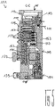
- the vacuum pump 111 comprises the electric motor 125 for rotatingly driving the rotor 149.
- the armature of the electric motor 125 is formed by the rotor 149, the rotor shaft 153 of which extends through the motor stator 217.
- a permanent magnet arrangement can be arranged radially on the outside or embedded on the section of the rotor shaft 153 extending through the motor stator 217.
- the motor stator 217 is fixed in the housing within the motor compartment 137 provided for the electric motor 125.
- a sealing gas which is also referred to as a flushing gas and which can be air or nitrogen, for example, can enter the engine compartment 137 via the sealing gas connection 135.
- the electric motor 125 can be protected from process gas, e.g. from corrosive components of the process gas, via the sealing gas.
- the engine compartment 137 can also be evacuated via the pump outlet 117, i.e. the vacuum pressure produced by the backing pump connected to the pump outlet 117 is at least approximately in the engine compartment 137.
- a so-called and known labyrinth seal 223 can also be provided between the rotor hub 161 and a wall 221 delimiting the engine compartment 137, in particular to achieve better sealing of the motor compartment 217 from the Holweck pump stages located radially outside.
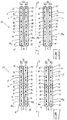
- Fig. 6 shows a cross-sectional view of a permanent magnet bearing 10 according to the invention according to a first embodiment, which can be used in functional terms instead of the permanent magnet bearing 183 of the turbo-molecular pump 111.
- the permanent magnetic bearing 10 comprises, viewed in the direction of an axis of rotation D of the permanent magnetic bearing 10, two successive pairs 12 of hollow cylindrical monolithic permanent magnets 14a, 14b (hereinafter referred to as permanent magnets 14a, 14b). It goes without saying that the permanent magnet bearing 10 can comprise only one pair 12 of permanent magnets 14a, 14b or also more than two pairs 12 of permanent magnets 14a, 14b, as indicated by the continuation points continuing in the axial direction.
- the two permanent magnets 14a that follow one another in the axial direction can be attached on the rotor side, ie on the rotor 149 of the turbo molecular pump 111 be.
- the two monolithic permanent magnets 14b which can be attached to the stator 150 of the turbo-molecular pump 111 on the stator side, are arranged radially within the rotor-side permanent magnets 14a.
- the two permanent magnets 14a on the rotor side are arranged such that they can rotate relative to the two permanent magnets 14b on the stator side with respect to the axis of rotation D of the magnetic bearing 10.
- the stator-side permanent magnets 14b could also be arranged the other way round radially outside of the rotor-side permanent magnets 14a.
- the rotor-side and stator-side permanent magnets 14a, 14b each have a longitudinal axis L.
- the longitudinal axes L of the rotor-side and stator-side permanent magnets 14a, 14b coincide with the axis of rotation D of the permanent magnet bearing 10.
- each of the permanent magnets 14a, 14b of the permanent magnet bearing 10 has a plurality of axially arranged and at least approximately axially magnetized sections 16, 16 ', the magnetizations of which are aligned alternately opposite to one another, which is shown in FIG Figures 6 to 8 is indicated by alternately oppositely aligned vector arrows P, P '.
- the axial dimensions of the two end sections 16 'of a respective permanent magnet 14a, 14b differ from the axial dimensions of the sections 16 adjacent to the end sections 16'. Specifically, the axial dimensions of the end sections 16 'are half less than those of the adjacent sections 16. In contrast, the axial dimensions of all the other sections 16 of each permanent magnet 14a, 14b arranged between the two end sections 16 'are at least approximately the same.
- a total length of a respective permanent magnet 14a, 14b of 15 to 25 mm, preferably 17 to 23 mm and particularly preferably 19 to 21 mm results.
- the sections 16, 16 ' typically have a width of 1 to 10 mm, preferably 2 to 9 mm and particularly preferably 3 to 8 mm.
- Fig. 7 shows a permanent magnet bearing 10 according to the invention according to a second embodiment, which differs from the permanent magnet bearing 10 according to the first embodiment in that adjoining end sections 16 'of the permanent magnets 14a, 14b following one another in the direction of the axis of rotation D of the permanent magnet bearing 10 each have opposite magnetizations. Since the radial rigidity of a permanent magnet bearing 10 is increased by the number of oppositely magnetized sections per unit of length, an arrangement of the pairs 12 of permanent magnets 14a, 14b in the permanent magnet bearing 10 according to the second embodiment has the advantage that this compared to the permanent magnet bearing 10 according to the first embodiment has a higher radial bearing rigidity.
- Fig. 8 shows a cross-sectional view of an arrangement which can be used to manufacture a monolithic permanent magnet 14 according to the invention from a body 18 made of magnetizable material.
- Fig. 8 only one half of the permanent magnet 14 or the body 18 is shown, the other half can also be imagined on the left side of the longitudinal axis L of the permanent magnet 14 or body 18 due to the rotationally symmetrical design of the hollow cylindrical permanent magnet 14 or body 18.
- the body 18 can for example consist of iron, a ferrimagnetic ceramic (ferrites) or a magnetizable plastic. However, it is preferred to use magnetizable materials which include rare earth metals, such as samarium cobalt (SmCo) or neodymium iron boron (NdFeB). The body 18 can be produced by sintering the magnetizable materials.
- magnetizable materials which include rare earth metals, such as samarium cobalt (SmCo) or neodymium iron boron (NdFeB).
- the body 18 can be produced by sintering the magnetizable materials.
- the assembly comprises an inner coil 20 and an outer coil 22, the inner coil 20 being arranged radially inward of the body 18 and the outer coil 22 being arranged radially outside the body.
- Both coils 20, 22 comprise a plurality of axially successive windings 24, with the windings 24 being the inner Coil 20 and the windings 24 of the outer coil 22, viewed in the direction of the longitudinal axis L of the body 18, are arranged at least approximately at the same height. Based on Fig. 8 it can be seen that in each case a pair of windings 24 arranged at the same height protrudes axially at the axial ends of the body 18.
- the windings 24 have a rectangular conductor cross-section with a radial dimension b and an axial dimension h, the windings being separated from one another in the axial direction by the distance d. According to a preferred embodiment, at least one of the windings 24 of the inner coil 20 and / or the outer coil 22 can be activated separately from the other windings.
- a hollow cylindrical body 18 made of magnetizable material is arranged between the inner coil 20 and the outer coil 22 in such a way that a pair of windings 24 arranged at the same height protrudes axially at the axial ends of the body 18.
- a voltage is applied to the coils 20, 22 to generate a current flow through the windings 24 in such a way that the resulting current flow through the windings 24 of the inner and outer coils 20, 22 is directed in the opposite direction.
- the magnetic field generated between the inner and outer windings 24 thus forms a monolithic, hollow-cylindrical permanent magnet 14 from the body 18.
- the permanent magnet 14 can also be produced from a body 18 configured as a solid cylinder made of magnetizable material, it being understood that there is then no need to arrange an inner coil 20 inside the magnetizable body 18.
Landscapes
- Engineering & Computer Science (AREA)
- General Engineering & Computer Science (AREA)
- Power Engineering (AREA)
- Mechanical Engineering (AREA)
- Physics & Mathematics (AREA)
- Electromagnetism (AREA)
- Manufacturing & Machinery (AREA)
- Non-Positive Displacement Air Blowers (AREA)
- Magnetic Bearings And Hydrostatic Bearings (AREA)
Claims (17)
- Aimant permanent monolithique (14, 14a, 14b), en particulier pour un palier à aimants permanents (10) d'une pompe à vide, présentant un axe longitudinal (L) et plusieurs portions (16, 16') disposées le long dudit axe et magnétisées au moins approximativement axialement, dont les magnétisations sont respectivement orientées en alternance dans des directions opposées l'une à l'autre,
caractérisé en ce que
la dimension et/ou magnétisation axiale d'au moins une portion magnétisée (16) et la dimension et/ou magnétisation axiale d'au moins une autre portion magnétisée (16) diffèrent l'une de l'autre. - Aimant permanent monolithique (14, 14a, 14b) selon la revendication 1,
caractérisé en ce que
la dimension et/ou magnétisation axiale de ladite au moins une portion magnétisée (16) est plus petite, en particulier moitié plus petite, que la dimension et/ou magnétisation axiale de l'autre portion magnétisée (16). - Aimant permanent monolithique (14, 14a, 14b) selon la revendication 1 ou 2,
caractérisé en ce que
la dimension et/ou magnétisation axiale d'une ou de chaque portion d'extrémité magnétisée (16') et la dimension et/ou magnétisation axiale d'une portion magnétisée (16) adjacente à la ou à chaque portion d'extrémité (16') diffèrent l'une de l'autre. - Aimant permanent monolithique (14, 14a, 14b) selon la revendication 2 ou 3,
caractérisé en ce que
les dimensions et/ou magnétisations axiales de toutes les portions (16) de l'aimant permanent monolithique (14, 14a, 14b) disposées entre deux portions d'extrémité (16') sont au moins approximativement de taille égale. - Aimant permanent monolithique (14, 14a, 14b) selon l'une au moins des revendications précédentes,
caractérisé en ce que
toutes les portions de l'aimant permanent monolithique (14, 14a, 14b) sont magnétiquement saturées. - Aimant permanent monolithique (14, 14a, 14b) selon l'une au moins des revendications précédentes,
caractérisé par
un nombre impair de portions magnétisées (16, 16'). - Aimant permanent monolithique (14, 14a, 14b) selon l'une au moins des revendications précédentes,
caractérisé en ce que
l'aimant permanent (14, 14a, 14b) est réalisé cylindrique creux. - Palier à aimants permanents (10), en particulier pour une pompe à vide, comportant une paire (12) d'aimants permanents monolithiques (14a, 14b) selon l'une au moins des revendications précédentes, dont un aimant permanent (14a) est monté de façon mobile en rotation par rapport à l'autre aimant permanent (14b) autour d'un axe de rotation (D) au moins approximativement parallèle aux axes longitudinaux (L) des aimants permanents (14a, 14b) ;
dans lequel
ledit un aimant permanent (14b) est disposé radialement à l'intérieur de l'autre aimant permanent (14a) de telle manière que des portions radialement adjacentes (16, 16') des aimants permanents monolithiques extérieur et intérieur (14a, 14b) sont au moins approximativement au même niveau, vu dans la direction de l'axe de rotation (D) ; et
les magnétisations des portions radialement adjacentes (16, 16') des aimants permanents monolithiques extérieur et intérieur (14a, 14b) sont orientées au moins approximativement dans le même sens. - Palier à aimants permanents (10) selon la revendication 8,
caractérisé en ce que
le palier à aimants permanents (10) est formé par au moins deux paires (12) d'aimants permanents monolithiques (14a, 14b) qui se suivent, vues dans la direction de l'axe de rotation (D), et des portions adjacentes (16, 16') des aimants permanents successifs (14a, 14b) présentent des magnétisations respectives opposées. - Palier à aimants permanents (10) selon la revendication 8 ou 9,
caractérisé en ce que
les aimants permanents (14a, 14b) de la ou de chaque paire d'aimants permanents (14a, 14b) sont réalisés cylindriques creux. - Pompe à vide, en particulier pompe turbomoléculaire (111), comprenant un rotor (149) et un stator (150) et un palier à aimants permanents (10) selon l'une au moins des revendications 8 à 10, l'un des aimants permanents monolithiques (14a) étant disposé du côté du rotor et l'autre aimant permanent monolithique (14b) étant disposé du côté du stator.
- Procédé de fabrication d'un aimant permanent monolithique (14), comprenant les étapes suivantes consistant à :- fournir un corps (18) en matériau magnétisable, définissant un axe longitudinal (L) ;- placer le corps (18) à l'intérieur d'une bobine extérieure (22) entourant le corps (18) et comportant plusieurs enroulements axialement successifs (24) ; et- appliquer une tension à la bobine (22) pour générer un flux de courant à travers les enroulements (24), de telle sorte que le flux de courant résultant dans les enroulements axialement successifs (24) est dirigé dans des sens opposés pour former un aimant permanent monolithique (14) selon l'une au moins des revendications 1 à 7 à partir du corps (18) par le champ magnétique ainsi induit.
- Procédé selon la revendication 12,
caractérisé par les étapes consistant à :- fournir un corps cylindrique creux (18) en matériau magnétisable, définissant un axe longitudinal (L) ;- placer en supplément une bobine intérieure (20), ayant plusieurs enroulements axialement successifs (24) à l'intérieur du corps (18), les enroulements (24) de la bobine intérieure (20) et de la bobine extérieure (22) étant disposés au moins approximativement au même niveau, vu dans la direction de l'axe longitudinal (L) du corps (18) ; et- appliquer une tension pour générer un flux de courant à travers les enroulements (24) des bobines intérieure et extérieure (20, 22), de telle sorte que le flux de courant résultant à travers les enroulements des bobines intérieure et extérieure (20, 22) est dirigé en sens opposés pour former un aimant permanent monolithique (14, 14a, 14b) cylindrique creux à partir du corps (18) par le champ magnétique induit entre les enroulements intérieurs et extérieurs (24). - Procédé selon la revendication 12 ou 13,
caractérisé en ce que
les enroulements (24) ont une section transversale conductrice rectangulaire, en particulier carrée. - Procédé selon l'une au moins des revendications 12 à 14,
caractérisé en ce que
l'un au moins des enroulements (24) d'une bobine (20, 22) est pilotable séparément des autres enroulements (24). - Procédé selon l'une au moins des revendications 12 à 15,
caractérisé en ce que
la dimension axiale (h) d'au moins un enroulement (24) d'une bobine (20, 22) diffère de la dimension axiale (h) d'au moins un autre enroulement (24) de la bobine (20, 22) ; et/ou au moins un enroulement (24) d'une bobine (20, 22), lorsqu'une tension est appliquée, génère un champ magnétique par le flux de courant résultant, qui diffère du champ magnétique d'un autre enroulement (24) de la bobine (20, 22). - Procédé selon l'une au moins des revendications 12 à 15,
caractérisé en ce que
au moins un enroulement (24) d'une bobine (20, 22) fait saillie au-delà d'une extrémité axiale du corps (18).
Priority Applications (3)
| Application Number | Priority Date | Filing Date | Title |
|---|---|---|---|
| EP17165109.4A EP3385961B1 (fr) | 2017-04-05 | 2017-04-05 | Aimant permanent monolithique |
| JP2017227380A JP6611780B2 (ja) | 2017-04-05 | 2017-11-28 | モノリス式の永久磁石 |
| CN201711326866.1A CN108691801B (zh) | 2017-04-05 | 2017-12-13 | 一种单片永磁体 |
Applications Claiming Priority (1)
| Application Number | Priority Date | Filing Date | Title |
|---|---|---|---|
| EP17165109.4A EP3385961B1 (fr) | 2017-04-05 | 2017-04-05 | Aimant permanent monolithique |
Publications (2)
| Publication Number | Publication Date |
|---|---|
| EP3385961A1 EP3385961A1 (fr) | 2018-10-10 |
| EP3385961B1 true EP3385961B1 (fr) | 2021-09-01 |
Family
ID=58544740
Family Applications (1)
| Application Number | Title | Priority Date | Filing Date |
|---|---|---|---|
| EP17165109.4A Active EP3385961B1 (fr) | 2017-04-05 | 2017-04-05 | Aimant permanent monolithique |
Country Status (3)
| Country | Link |
|---|---|
| EP (1) | EP3385961B1 (fr) |
| JP (1) | JP6611780B2 (fr) |
| CN (1) | CN108691801B (fr) |
Families Citing this family (4)
| Publication number | Priority date | Publication date | Assignee | Title |
|---|---|---|---|---|
| WO2021116637A1 (fr) * | 2019-12-09 | 2021-06-17 | Edwards Limited | Appareil et procédé de magnétisation |
| CN111524681B (zh) * | 2020-03-29 | 2021-07-27 | 靳普 | 一种永磁体的充磁方法及高速转子的制造方法 |
| WO2025071964A1 (fr) * | 2023-09-27 | 2025-04-03 | Sonos, Inc. | Ensemble aimant |
| CN118902666A (zh) * | 2024-09-14 | 2024-11-08 | 南京中医药大学 | 一种多功能脑外伤动物实验装置 |
Citations (1)
| Publication number | Priority date | Publication date | Assignee | Title |
|---|---|---|---|---|
| EP3146222A1 (fr) * | 2014-05-20 | 2017-03-29 | Edwards Limited | Aimant permanent annulaire allongé comportant une pluralité de zones magnétisées orientées axialement et palier magnétique comprenant un tel aimant annulaire |
Family Cites Families (10)
| Publication number | Priority date | Publication date | Assignee | Title |
|---|---|---|---|---|
| JPH11325075A (ja) * | 1998-05-13 | 1999-11-26 | Sankyo Seiki Mfg Co Ltd | 磁気軸受 |
| JP2002310154A (ja) * | 2001-04-18 | 2002-10-23 | Seiko Epson Corp | 永久磁石磁気回路及び超電導軸受装置 |
| CN1148762C (zh) * | 2002-06-14 | 2004-05-05 | 钢铁研究总院 | 多织构整体烧结成型稀土永磁体及制备方法 |
| TW200521350A (en) * | 2003-12-25 | 2005-07-01 | Delta Electronics Inc | Magnetic bearing system |
| GB2490863B (en) * | 2011-05-06 | 2018-04-18 | Edwards Ltd | Magnetic bearing assembly |
| DE102014103060B4 (de) * | 2014-03-07 | 2019-01-03 | Pfeiffer Vacuum Gmbh | Verfahren zum Wuchten eines Rotors einer Vakuumpumpe oder eines Rotors einer Rotationseinheit für eine Vakuumpumpe |
| DE102015113681B3 (de) * | 2015-08-18 | 2016-11-24 | Pfeiffer Vacuum Gmbh | Verfahren zum Reduzieren eines magnetischen Streuvektorfelds einer Vakuumpumpe oder Rotationseinheit sowie Vakuumpumpe und Rotationseinheit |
| EP3135932B1 (fr) * | 2015-08-24 | 2018-10-31 | Pfeiffer Vacuum Gmbh | Pompe à vide et palier à aimant permanent |
| EP3196471B1 (fr) * | 2016-01-19 | 2023-08-23 | Pfeiffer Vacuum Gmbh | Pompe a vide |
| CN205645431U (zh) * | 2016-05-09 | 2016-10-12 | 深圳市高励磁技术有限公司 | 一种高效可靠无短路电流多极充磁机 |
-
2017
- 2017-04-05 EP EP17165109.4A patent/EP3385961B1/fr active Active
- 2017-11-28 JP JP2017227380A patent/JP6611780B2/ja active Active
- 2017-12-13 CN CN201711326866.1A patent/CN108691801B/zh active Active
Patent Citations (1)
| Publication number | Priority date | Publication date | Assignee | Title |
|---|---|---|---|---|
| EP3146222A1 (fr) * | 2014-05-20 | 2017-03-29 | Edwards Limited | Aimant permanent annulaire allongé comportant une pluralité de zones magnétisées orientées axialement et palier magnétique comprenant un tel aimant annulaire |
Also Published As
| Publication number | Publication date |
|---|---|
| EP3385961A1 (fr) | 2018-10-10 |
| JP6611780B2 (ja) | 2019-11-27 |
| JP2018178990A (ja) | 2018-11-15 |
| CN108691801A (zh) | 2018-10-23 |
| CN108691801B (zh) | 2021-07-09 |
Similar Documents
| Publication | Publication Date | Title |
|---|---|---|
| EP2503104B1 (fr) | Turbomachine | |
| EP3385961B1 (fr) | Aimant permanent monolithique | |
| EP0675289B1 (fr) | Pompe à friction | |
| DE102012022152A1 (de) | Elektrische Maschine und Rotor für eine elektrische Maschine | |
| EP3723240A1 (fr) | Moteur électrique à espace réduit permettant d'optimiser le débit magnétique entre le rotor et le stator | |
| DE102007056116A1 (de) | Permanenterregte elektrische Maschine | |
| EP2508769B1 (fr) | Dispositif de palier magnetique axial doté d'un remplissage en fer augmenté | |
| DE102013220495A1 (de) | Elektrische Maschine | |
| EP3447299B1 (fr) | Rondelle de calage | |
| EP3670924B1 (fr) | Pompe à vide et procédé de fabrication d'une telle pompe à vide | |
| EP2866343A1 (fr) | Pompe à vide | |
| DE102018106916B4 (de) | Antriebseinheit für einen Stellantrieb und Stellantrieb für einen Klappensteller | |
| EP3196471B1 (fr) | Pompe a vide | |
| EP4325061B1 (fr) | Pompe à vide turbomoléculaire | |
| EP4194700A1 (fr) | Pompe à vide avec étage de pompe de holweck à géométrie de holweck variable | |
| EP2273651A1 (fr) | Machine électrique | |
| EP3135932B1 (fr) | Pompe à vide et palier à aimant permanent | |
| EP3536965A1 (fr) | Pompe à vide dans laquelle le support d'un palier à roulement a une rigidité et/ou un amortissement réglable(s) | |
| DE102013112625A1 (de) | Elektrische Drehmaschine mit Magnetverstärkungsring | |
| EP3907406A1 (fr) | Pompe à vide | |
| DE102021107113A1 (de) | Bürstenloser Motor mit fluiddynamischem Lagersystem | |
| EP3244068B1 (fr) | Pompe à vide | |
| EP4038722A1 (fr) | Rotor à excitation permanente à géométrie d'aimant améliorée | |
| EP4273405B1 (fr) | Pompe à vide avec un étage de pompage de type holweck avec une géométrie holweck variable | |
| DE102014001023B4 (de) | Elektrische Maschine |
Legal Events
| Date | Code | Title | Description |
|---|---|---|---|
| PUAI | Public reference made under article 153(3) epc to a published international application that has entered the european phase |
Free format text: ORIGINAL CODE: 0009012 |
|
| STAA | Information on the status of an ep patent application or granted ep patent |
Free format text: STATUS: THE APPLICATION HAS BEEN PUBLISHED |
|
| AK | Designated contracting states |
Kind code of ref document: A1 Designated state(s): AL AT BE BG CH CY CZ DE DK EE ES FI FR GB GR HR HU IE IS IT LI LT LU LV MC MK MT NL NO PL PT RO RS SE SI SK SM TR |
|
| AX | Request for extension of the european patent |
Extension state: BA ME |
|
| STAA | Information on the status of an ep patent application or granted ep patent |
Free format text: STATUS: REQUEST FOR EXAMINATION WAS MADE |
|
| 17P | Request for examination filed |
Effective date: 20190226 |
|
| RBV | Designated contracting states (corrected) |
Designated state(s): AL AT BE BG CH CY CZ DE DK EE ES FI FR GB GR HR HU IE IS IT LI LT LU LV MC MK MT NL NO PL PT RO RS SE SI SK SM TR |
|
| RIC1 | Information provided on ipc code assigned before grant |
Ipc: F04D 19/04 20060101ALI20210212BHEP Ipc: H01F 41/02 20060101ALI20210212BHEP Ipc: F16C 32/04 20060101ALI20210212BHEP Ipc: F04D 29/05 20060101ALI20210212BHEP Ipc: H01F 13/00 20060101ALI20210212BHEP Ipc: H01F 7/02 20060101AFI20210212BHEP |
|
| GRAP | Despatch of communication of intention to grant a patent |
Free format text: ORIGINAL CODE: EPIDOSNIGR1 |
|
| STAA | Information on the status of an ep patent application or granted ep patent |
Free format text: STATUS: GRANT OF PATENT IS INTENDED |
|
| INTG | Intention to grant announced |
Effective date: 20210409 |
|
| GRAS | Grant fee paid |
Free format text: ORIGINAL CODE: EPIDOSNIGR3 |
|
| GRAA | (expected) grant |
Free format text: ORIGINAL CODE: 0009210 |
|
| STAA | Information on the status of an ep patent application or granted ep patent |
Free format text: STATUS: THE PATENT HAS BEEN GRANTED |
|
| AK | Designated contracting states |
Kind code of ref document: B1 Designated state(s): AL AT BE BG CH CY CZ DE DK EE ES FI FR GB GR HR HU IE IS IT LI LT LU LV MC MK MT NL NO PL PT RO RS SE SI SK SM TR |
|
| REG | Reference to a national code |
Ref country code: GB Ref legal event code: FG4D Free format text: NOT ENGLISH |
|
| REG | Reference to a national code |
Ref country code: CH Ref legal event code: EP Ref country code: AT Ref legal event code: REF Ref document number: 1427089 Country of ref document: AT Kind code of ref document: T Effective date: 20210915 |
|
| REG | Reference to a national code |
Ref country code: DE Ref legal event code: R096 Ref document number: 502017011338 Country of ref document: DE |
|
| REG | Reference to a national code |
Ref country code: IE Ref legal event code: FG4D Free format text: LANGUAGE OF EP DOCUMENT: GERMAN |
|
| REG | Reference to a national code |
Ref country code: LT Ref legal event code: MG9D |
|
| REG | Reference to a national code |
Ref country code: NL Ref legal event code: MP Effective date: 20210901 |
|
| PG25 | Lapsed in a contracting state [announced via postgrant information from national office to epo] |
Ref country code: SE Free format text: LAPSE BECAUSE OF FAILURE TO SUBMIT A TRANSLATION OF THE DESCRIPTION OR TO PAY THE FEE WITHIN THE PRESCRIBED TIME-LIMIT Effective date: 20210901 Ref country code: RS Free format text: LAPSE BECAUSE OF FAILURE TO SUBMIT A TRANSLATION OF THE DESCRIPTION OR TO PAY THE FEE WITHIN THE PRESCRIBED TIME-LIMIT Effective date: 20210901 Ref country code: NO Free format text: LAPSE BECAUSE OF FAILURE TO SUBMIT A TRANSLATION OF THE DESCRIPTION OR TO PAY THE FEE WITHIN THE PRESCRIBED TIME-LIMIT Effective date: 20211201 Ref country code: ES Free format text: LAPSE BECAUSE OF FAILURE TO SUBMIT A TRANSLATION OF THE DESCRIPTION OR TO PAY THE FEE WITHIN THE PRESCRIBED TIME-LIMIT Effective date: 20210901 Ref country code: FI Free format text: LAPSE BECAUSE OF FAILURE TO SUBMIT A TRANSLATION OF THE DESCRIPTION OR TO PAY THE FEE WITHIN THE PRESCRIBED TIME-LIMIT Effective date: 20210901 Ref country code: HR Free format text: LAPSE BECAUSE OF FAILURE TO SUBMIT A TRANSLATION OF THE DESCRIPTION OR TO PAY THE FEE WITHIN THE PRESCRIBED TIME-LIMIT Effective date: 20210901 Ref country code: BG Free format text: LAPSE BECAUSE OF FAILURE TO SUBMIT A TRANSLATION OF THE DESCRIPTION OR TO PAY THE FEE WITHIN THE PRESCRIBED TIME-LIMIT Effective date: 20211201 Ref country code: LT Free format text: LAPSE BECAUSE OF FAILURE TO SUBMIT A TRANSLATION OF THE DESCRIPTION OR TO PAY THE FEE WITHIN THE PRESCRIBED TIME-LIMIT Effective date: 20210901 |
|
| PG25 | Lapsed in a contracting state [announced via postgrant information from national office to epo] |
Ref country code: PL Free format text: LAPSE BECAUSE OF FAILURE TO SUBMIT A TRANSLATION OF THE DESCRIPTION OR TO PAY THE FEE WITHIN THE PRESCRIBED TIME-LIMIT Effective date: 20210901 Ref country code: LV Free format text: LAPSE BECAUSE OF FAILURE TO SUBMIT A TRANSLATION OF THE DESCRIPTION OR TO PAY THE FEE WITHIN THE PRESCRIBED TIME-LIMIT Effective date: 20210901 Ref country code: GR Free format text: LAPSE BECAUSE OF FAILURE TO SUBMIT A TRANSLATION OF THE DESCRIPTION OR TO PAY THE FEE WITHIN THE PRESCRIBED TIME-LIMIT Effective date: 20211202 |
|
| PG25 | Lapsed in a contracting state [announced via postgrant information from national office to epo] |
Ref country code: IS Free format text: LAPSE BECAUSE OF FAILURE TO SUBMIT A TRANSLATION OF THE DESCRIPTION OR TO PAY THE FEE WITHIN THE PRESCRIBED TIME-LIMIT Effective date: 20220101 Ref country code: SM Free format text: LAPSE BECAUSE OF FAILURE TO SUBMIT A TRANSLATION OF THE DESCRIPTION OR TO PAY THE FEE WITHIN THE PRESCRIBED TIME-LIMIT Effective date: 20210901 Ref country code: SK Free format text: LAPSE BECAUSE OF FAILURE TO SUBMIT A TRANSLATION OF THE DESCRIPTION OR TO PAY THE FEE WITHIN THE PRESCRIBED TIME-LIMIT Effective date: 20210901 Ref country code: RO Free format text: LAPSE BECAUSE OF FAILURE TO SUBMIT A TRANSLATION OF THE DESCRIPTION OR TO PAY THE FEE WITHIN THE PRESCRIBED TIME-LIMIT Effective date: 20210901 Ref country code: PT Free format text: LAPSE BECAUSE OF FAILURE TO SUBMIT A TRANSLATION OF THE DESCRIPTION OR TO PAY THE FEE WITHIN THE PRESCRIBED TIME-LIMIT Effective date: 20220103 Ref country code: NL Free format text: LAPSE BECAUSE OF FAILURE TO SUBMIT A TRANSLATION OF THE DESCRIPTION OR TO PAY THE FEE WITHIN THE PRESCRIBED TIME-LIMIT Effective date: 20210901 Ref country code: EE Free format text: LAPSE BECAUSE OF FAILURE TO SUBMIT A TRANSLATION OF THE DESCRIPTION OR TO PAY THE FEE WITHIN THE PRESCRIBED TIME-LIMIT Effective date: 20210901 Ref country code: AL Free format text: LAPSE BECAUSE OF FAILURE TO SUBMIT A TRANSLATION OF THE DESCRIPTION OR TO PAY THE FEE WITHIN THE PRESCRIBED TIME-LIMIT Effective date: 20210901 |
|
| REG | Reference to a national code |
Ref country code: DE Ref legal event code: R097 Ref document number: 502017011338 Country of ref document: DE |
|
| PLBE | No opposition filed within time limit |
Free format text: ORIGINAL CODE: 0009261 |
|
| STAA | Information on the status of an ep patent application or granted ep patent |
Free format text: STATUS: NO OPPOSITION FILED WITHIN TIME LIMIT |
|
| PG25 | Lapsed in a contracting state [announced via postgrant information from national office to epo] |
Ref country code: DK Free format text: LAPSE BECAUSE OF FAILURE TO SUBMIT A TRANSLATION OF THE DESCRIPTION OR TO PAY THE FEE WITHIN THE PRESCRIBED TIME-LIMIT Effective date: 20210901 |
|
| 26N | No opposition filed |
Effective date: 20220602 |
|
| PG25 | Lapsed in a contracting state [announced via postgrant information from national office to epo] |
Ref country code: SI Free format text: LAPSE BECAUSE OF FAILURE TO SUBMIT A TRANSLATION OF THE DESCRIPTION OR TO PAY THE FEE WITHIN THE PRESCRIBED TIME-LIMIT Effective date: 20210901 |
|
| REG | Reference to a national code |
Ref country code: CH Ref legal event code: PL |
|
| REG | Reference to a national code |
Ref country code: BE Ref legal event code: MM Effective date: 20220430 |
|
| PG25 | Lapsed in a contracting state [announced via postgrant information from national office to epo] |
Ref country code: MC Free format text: LAPSE BECAUSE OF FAILURE TO SUBMIT A TRANSLATION OF THE DESCRIPTION OR TO PAY THE FEE WITHIN THE PRESCRIBED TIME-LIMIT Effective date: 20210901 Ref country code: LU Free format text: LAPSE BECAUSE OF NON-PAYMENT OF DUE FEES Effective date: 20220405 Ref country code: LI Free format text: LAPSE BECAUSE OF NON-PAYMENT OF DUE FEES Effective date: 20220430 Ref country code: FR Free format text: LAPSE BECAUSE OF NON-PAYMENT OF DUE FEES Effective date: 20220430 Ref country code: CH Free format text: LAPSE BECAUSE OF NON-PAYMENT OF DUE FEES Effective date: 20220430 |
|
| PG25 | Lapsed in a contracting state [announced via postgrant information from national office to epo] |
Ref country code: BE Free format text: LAPSE BECAUSE OF NON-PAYMENT OF DUE FEES Effective date: 20220430 |
|
| PG25 | Lapsed in a contracting state [announced via postgrant information from national office to epo] |
Ref country code: IE Free format text: LAPSE BECAUSE OF NON-PAYMENT OF DUE FEES Effective date: 20220405 |
|
| REG | Reference to a national code |
Ref country code: AT Ref legal event code: MM01 Ref document number: 1427089 Country of ref document: AT Kind code of ref document: T Effective date: 20220405 |
|
| PG25 | Lapsed in a contracting state [announced via postgrant information from national office to epo] |
Ref country code: AT Free format text: LAPSE BECAUSE OF NON-PAYMENT OF DUE FEES Effective date: 20220405 |
|
| PG25 | Lapsed in a contracting state [announced via postgrant information from national office to epo] |
Ref country code: HU Free format text: LAPSE BECAUSE OF FAILURE TO SUBMIT A TRANSLATION OF THE DESCRIPTION OR TO PAY THE FEE WITHIN THE PRESCRIBED TIME-LIMIT; INVALID AB INITIO Effective date: 20170405 |
|
| PG25 | Lapsed in a contracting state [announced via postgrant information from national office to epo] |
Ref country code: MK Free format text: LAPSE BECAUSE OF FAILURE TO SUBMIT A TRANSLATION OF THE DESCRIPTION OR TO PAY THE FEE WITHIN THE PRESCRIBED TIME-LIMIT Effective date: 20210901 Ref country code: CY Free format text: LAPSE BECAUSE OF FAILURE TO SUBMIT A TRANSLATION OF THE DESCRIPTION OR TO PAY THE FEE WITHIN THE PRESCRIBED TIME-LIMIT Effective date: 20210901 |
|
| PG25 | Lapsed in a contracting state [announced via postgrant information from national office to epo] |
Ref country code: MT Free format text: LAPSE BECAUSE OF FAILURE TO SUBMIT A TRANSLATION OF THE DESCRIPTION OR TO PAY THE FEE WITHIN THE PRESCRIBED TIME-LIMIT Effective date: 20210901 |
|
| PGFP | Annual fee paid to national office [announced via postgrant information from national office to epo] |
Ref country code: DE Payment date: 20250625 Year of fee payment: 9 |
|
| PGFP | Annual fee paid to national office [announced via postgrant information from national office to epo] |
Ref country code: GB Payment date: 20250423 Year of fee payment: 9 |
|
| PGFP | Annual fee paid to national office [announced via postgrant information from national office to epo] |
Ref country code: IT Payment date: 20250424 Year of fee payment: 9 |
|
| PGFP | Annual fee paid to national office [announced via postgrant information from national office to epo] |
Ref country code: CZ Payment date: 20250401 Year of fee payment: 9 |
|
| PG25 | Lapsed in a contracting state [announced via postgrant information from national office to epo] |
Ref country code: TR Free format text: LAPSE BECAUSE OF FAILURE TO SUBMIT A TRANSLATION OF THE DESCRIPTION OR TO PAY THE FEE WITHIN THE PRESCRIBED TIME-LIMIT Effective date: 20210901 |