EP3385961A1 - Monolithic permanent magnet - Google Patents
Monolithic permanent magnet Download PDFInfo
- Publication number
- EP3385961A1 EP3385961A1 EP17165109.4A EP17165109A EP3385961A1 EP 3385961 A1 EP3385961 A1 EP 3385961A1 EP 17165109 A EP17165109 A EP 17165109A EP 3385961 A1 EP3385961 A1 EP 3385961A1
- Authority
- EP
- European Patent Office
- Prior art keywords
- permanent magnet
- monolithic
- coil
- windings
- magnetized
- Prior art date
- Legal status (The legal status is an assumption and is not a legal conclusion. Google has not performed a legal analysis and makes no representation as to the accuracy of the status listed.)
- Granted
Links
- 230000005415 magnetization Effects 0.000 claims abstract description 52
- 238000004804 winding Methods 0.000 claims description 49
- 230000005291 magnetic effect Effects 0.000 claims description 39
- 239000000463 material Substances 0.000 claims description 12
- 238000000034 method Methods 0.000 claims description 12
- 239000004020 conductor Substances 0.000 claims description 6
- 229920006395 saturated elastomer Polymers 0.000 claims description 5
- 238000004519 manufacturing process Methods 0.000 claims description 3
- 239000007789 gas Substances 0.000 description 15
- 239000002826 coolant Substances 0.000 description 9
- 230000008569 process Effects 0.000 description 5
- 238000005086 pumping Methods 0.000 description 5
- 239000007921 spray Substances 0.000 description 5
- XEEYBQQBJWHFJM-UHFFFAOYSA-N Iron Chemical compound [Fe] XEEYBQQBJWHFJM-UHFFFAOYSA-N 0.000 description 4
- KPLQYGBQNPPQGA-UHFFFAOYSA-N cobalt samarium Chemical compound [Co].[Sm] KPLQYGBQNPPQGA-UHFFFAOYSA-N 0.000 description 4
- 229910001172 neodymium magnet Inorganic materials 0.000 description 4
- 238000005096 rolling process Methods 0.000 description 4
- 229910000938 samarium–cobalt magnet Inorganic materials 0.000 description 4
- 238000007789 sealing Methods 0.000 description 4
- 230000008901 benefit Effects 0.000 description 3
- 230000009467 reduction Effects 0.000 description 3
- 238000003860 storage Methods 0.000 description 3
- IJGRMHOSHXDMSA-UHFFFAOYSA-N Atomic nitrogen Chemical compound N#N IJGRMHOSHXDMSA-UHFFFAOYSA-N 0.000 description 2
- QJVKUMXDEUEQLH-UHFFFAOYSA-N [B].[Fe].[Nd] Chemical compound [B].[Fe].[Nd] QJVKUMXDEUEQLH-UHFFFAOYSA-N 0.000 description 2
- 239000000919 ceramic Substances 0.000 description 2
- 230000005293 ferrimagnetic effect Effects 0.000 description 2
- 238000011010 flushing procedure Methods 0.000 description 2
- 229910052742 iron Inorganic materials 0.000 description 2
- 229910052761 rare earth metal Inorganic materials 0.000 description 2
- 150000002910 rare earth metals Chemical class 0.000 description 2
- 238000005245 sintering Methods 0.000 description 2
- 239000007787 solid Substances 0.000 description 2
- 125000006850 spacer group Chemical group 0.000 description 2
- 229910000859 α-Fe Inorganic materials 0.000 description 2
- 230000002745 absorbent Effects 0.000 description 1
- 239000002250 absorbent Substances 0.000 description 1
- 230000009471 action Effects 0.000 description 1
- 230000004075 alteration Effects 0.000 description 1
- 230000005540 biological transmission Effects 0.000 description 1
- 230000000903 blocking effect Effects 0.000 description 1
- 230000008859 change Effects 0.000 description 1
- 238000001816 cooling Methods 0.000 description 1
- 230000007423 decrease Effects 0.000 description 1
- 230000001419 dependent effect Effects 0.000 description 1
- 238000010894 electron beam technology Methods 0.000 description 1
- 230000004907 flux Effects 0.000 description 1
- 239000000314 lubricant Substances 0.000 description 1
- 230000001050 lubricating effect Effects 0.000 description 1
- 229910052757 nitrogen Inorganic materials 0.000 description 1
- 238000010926 purge Methods 0.000 description 1
- 230000035945 sensitivity Effects 0.000 description 1
- 239000010409 thin film Substances 0.000 description 1
Images


Classifications
-
- H—ELECTRICITY
- H01—ELECTRIC ELEMENTS
- H01F—MAGNETS; INDUCTANCES; TRANSFORMERS; SELECTION OF MATERIALS FOR THEIR MAGNETIC PROPERTIES
- H01F7/00—Magnets
- H01F7/02—Permanent magnets [PM]
- H01F7/0205—Magnetic circuits with PM in general
- H01F7/021—Construction of PM
-
- F—MECHANICAL ENGINEERING; LIGHTING; HEATING; WEAPONS; BLASTING
- F04—POSITIVE - DISPLACEMENT MACHINES FOR LIQUIDS; PUMPS FOR LIQUIDS OR ELASTIC FLUIDS
- F04D—NON-POSITIVE-DISPLACEMENT PUMPS
- F04D19/00—Axial-flow pumps
- F04D19/02—Multi-stage pumps
- F04D19/04—Multi-stage pumps specially adapted to the production of a high vacuum, e.g. molecular pumps
- F04D19/048—Multi-stage pumps specially adapted to the production of a high vacuum, e.g. molecular pumps comprising magnetic bearings
-
- F—MECHANICAL ENGINEERING; LIGHTING; HEATING; WEAPONS; BLASTING
- F04—POSITIVE - DISPLACEMENT MACHINES FOR LIQUIDS; PUMPS FOR LIQUIDS OR ELASTIC FLUIDS
- F04D—NON-POSITIVE-DISPLACEMENT PUMPS
- F04D29/00—Details, component parts, or accessories
- F04D29/05—Shafts or bearings, or assemblies thereof, specially adapted for elastic fluid pumps
- F04D29/056—Bearings
- F04D29/058—Bearings magnetic; electromagnetic
-
- F—MECHANICAL ENGINEERING; LIGHTING; HEATING; WEAPONS; BLASTING
- F16—ENGINEERING ELEMENTS AND UNITS; GENERAL MEASURES FOR PRODUCING AND MAINTAINING EFFECTIVE FUNCTIONING OF MACHINES OR INSTALLATIONS; THERMAL INSULATION IN GENERAL
- F16C—SHAFTS; FLEXIBLE SHAFTS; ELEMENTS OR CRANKSHAFT MECHANISMS; ROTARY BODIES OTHER THAN GEARING ELEMENTS; BEARINGS
- F16C32/00—Bearings not otherwise provided for
- F16C32/04—Bearings not otherwise provided for using magnetic or electric supporting means
- F16C32/0406—Magnetic bearings
- F16C32/0408—Passive magnetic bearings
- F16C32/0423—Passive magnetic bearings with permanent magnets on both parts repelling each other
- F16C32/0425—Passive magnetic bearings with permanent magnets on both parts repelling each other for radial load mainly
-
- H—ELECTRICITY
- H01—ELECTRIC ELEMENTS
- H01F—MAGNETS; INDUCTANCES; TRANSFORMERS; SELECTION OF MATERIALS FOR THEIR MAGNETIC PROPERTIES
- H01F13/00—Apparatus or processes for magnetising or demagnetising
- H01F13/003—Methods and devices for magnetising permanent magnets
-
- H—ELECTRICITY
- H01—ELECTRIC ELEMENTS
- H01F—MAGNETS; INDUCTANCES; TRANSFORMERS; SELECTION OF MATERIALS FOR THEIR MAGNETIC PROPERTIES
- H01F41/00—Apparatus or processes specially adapted for manufacturing or assembling magnets, inductances or transformers; Apparatus or processes specially adapted for manufacturing materials characterised by their magnetic properties
- H01F41/02—Apparatus or processes specially adapted for manufacturing or assembling magnets, inductances or transformers; Apparatus or processes specially adapted for manufacturing materials characterised by their magnetic properties for manufacturing cores, coils, or magnets
- H01F41/0253—Apparatus or processes specially adapted for manufacturing or assembling magnets, inductances or transformers; Apparatus or processes specially adapted for manufacturing materials characterised by their magnetic properties for manufacturing cores, coils, or magnets for manufacturing permanent magnets
-
- F—MECHANICAL ENGINEERING; LIGHTING; HEATING; WEAPONS; BLASTING
- F16—ENGINEERING ELEMENTS AND UNITS; GENERAL MEASURES FOR PRODUCING AND MAINTAINING EFFECTIVE FUNCTIONING OF MACHINES OR INSTALLATIONS; THERMAL INSULATION IN GENERAL
- F16C—SHAFTS; FLEXIBLE SHAFTS; ELEMENTS OR CRANKSHAFT MECHANISMS; ROTARY BODIES OTHER THAN GEARING ELEMENTS; BEARINGS
- F16C19/00—Bearings with rolling contact, for exclusively rotary movement
- F16C19/02—Bearings with rolling contact, for exclusively rotary movement with bearing balls essentially of the same size in one or more circular rows
- F16C19/04—Bearings with rolling contact, for exclusively rotary movement with bearing balls essentially of the same size in one or more circular rows for radial load mainly
- F16C19/06—Bearings with rolling contact, for exclusively rotary movement with bearing balls essentially of the same size in one or more circular rows for radial load mainly with a single row or balls
-
- F—MECHANICAL ENGINEERING; LIGHTING; HEATING; WEAPONS; BLASTING
- F16—ENGINEERING ELEMENTS AND UNITS; GENERAL MEASURES FOR PRODUCING AND MAINTAINING EFFECTIVE FUNCTIONING OF MACHINES OR INSTALLATIONS; THERMAL INSULATION IN GENERAL
- F16C—SHAFTS; FLEXIBLE SHAFTS; ELEMENTS OR CRANKSHAFT MECHANISMS; ROTARY BODIES OTHER THAN GEARING ELEMENTS; BEARINGS
- F16C2360/00—Engines or pumps
- F16C2360/44—Centrifugal pumps
- F16C2360/45—Turbo-molecular pumps
-
- F—MECHANICAL ENGINEERING; LIGHTING; HEATING; WEAPONS; BLASTING
- F16—ENGINEERING ELEMENTS AND UNITS; GENERAL MEASURES FOR PRODUCING AND MAINTAINING EFFECTIVE FUNCTIONING OF MACHINES OR INSTALLATIONS; THERMAL INSULATION IN GENERAL
- F16C—SHAFTS; FLEXIBLE SHAFTS; ELEMENTS OR CRANKSHAFT MECHANISMS; ROTARY BODIES OTHER THAN GEARING ELEMENTS; BEARINGS
- F16C32/00—Bearings not otherwise provided for
- F16C32/04—Bearings not otherwise provided for using magnetic or electric supporting means
- F16C32/0402—Bearings not otherwise provided for using magnetic or electric supporting means combined with other supporting means, e.g. hybrid bearings with both magnetic and fluid supporting means
-
- F—MECHANICAL ENGINEERING; LIGHTING; HEATING; WEAPONS; BLASTING
- F16—ENGINEERING ELEMENTS AND UNITS; GENERAL MEASURES FOR PRODUCING AND MAINTAINING EFFECTIVE FUNCTIONING OF MACHINES OR INSTALLATIONS; THERMAL INSULATION IN GENERAL
- F16C—SHAFTS; FLEXIBLE SHAFTS; ELEMENTS OR CRANKSHAFT MECHANISMS; ROTARY BODIES OTHER THAN GEARING ELEMENTS; BEARINGS
- F16C39/00—Relieving load on bearings
- F16C39/02—Relieving load on bearings using mechanical means
Definitions
- the present invention relates to a monolithic permanent magnet, in particular for a permanent magnet bearing of a vacuum pump, having a longitudinal axis and a plurality of arranged along this and at least approximately axially magnetized sections whose magnetizations are each aligned alternately opposite to each other.
- Monolithic permanent magnets are known in principle and are used, for example, in vacuum pumps, in particular in turbomolecular pumps, for lubricant-free mounting of a rotor rotatable with respect to a stator.
- both the stator and the rotor each have at least one monolithic permanent magnet, which together form a permanent magnet bearing.
- the stray magnetic field can affect high-sensitivity applications, for example by deflecting an electron beam of an electron microscope due to the Lorentz force, which can cause aberrations. Also, the stray magnetic field may affect the magnetization of a vacuum-deposited high-sensitivity magnetic thin film. There is therefore a need for monolithic permanent magnets with a low stray magnetic field.
- the object is achieved by a monolithic permanent magnet having the features of claim 1 and in particular by the fact that the axial dimension and / or the magnetization of at least one magnetized portion and the axial dimension and / or the magnetization of at least one other magnetized portion differ.
- the invention is based on the finding that the stray magnetic field of a monolithic permanent magnet decreases when the axial dimension and / or magnetization of at least one magnetized section differ from the axial dimension and / or magnetization of at least one other magnetized section.
- the advantage of reducing stray magnetic field is that the monolithic permanent magnet can be used in applications where low stray magnetic field is indispensable, such as vacuum pump bearings used to evacuate electron microscopes.
- the use of the monolithic permanent magnet according to the invention is not limited to use in vacuum pumps. It is also conceivable that a monolithic permanent magnet according to the invention can be used wherever small stray magnetic fields are desirable, e.g. in audio amplifiers.
- Magnetization of a magnetized section is understood here as meaning the magnetic remanence which the magnetized section retains after the external magnetic field required for magnetizing, ie for achieving the magnetization, has been deactivated.
- a monolithic permanent magnet unlike a magnetic stack formed by a plurality of stacked individual magnets, is a one-piece magnet.
- the individual sections of the monolithic permanent magnet are therefore not visually recognizable as such, but differ only in their respective magnetization orientation.
- Each magnetized section has a magnetic north and south pole, conventionally the orientation of the magnetization being defined by a vector arrow originating in the interior of the magnetized section from the south pole and terminating at the north pole.
- the respective magnetized sections of the monolithic permanent magnet are magnetized at least approximately in the axial direction. This means that the magnetization orientation of a magnetized section is aligned at least approximately parallel to the longitudinal axis of the monolithic permanent magnet.
- the monolithic permanent magnet is preferably made of a magnetizable material, such as iron, a ferrimagnetic ceramic (ferrites) or a magnetizable plastic. It is also possible to use magnetizable materials which comprise rare earth metals, for example samarium cobalt (SmCo) or neodymium-iron-boron (NdFeB). The magnetizable materials can be added, for example, by a sintering process.
- a magnetizable material such as iron, a ferrimagnetic ceramic (ferrites) or a magnetizable plastic.
- magnetizable materials which comprise rare earth metals, for example samarium cobalt (SmCo) or neodymium-iron-boron (NdFeB).
- SmCo samarium cobalt
- NdFeB neodymium-iron-boron
- a monolithic permanent magnet may have an overall length of between 15 and 25 mm, preferably between 17 and 23 mm, and more preferably between 19 and 21 mm.
- the width of a section may be between 1 and 10 mm, preferably between 2 and 9 mm and more preferably between 3 and 8 mm.
- the axial dimension and / or magnetization of the at least one magnetized section can be smaller, in particular smaller by half, than the axial dimension and / or magnetization of the other magnetized section.
- a particularly large reduction of the stray magnetic field can be achieved if the axial dimension and / or magnetization of one or each end portion and the axial dimension and / or magnetization of a magnetized portion adjacent to the or each end portion differ.
- the axial dimension and / or magnetization of the or each end portion is at least approximately one-half less than that of the adjacent portion. It will be understood that the axial dimension and / or magnetization of the or each end portion may in principle be less than that of the adjacent portion, e.g. by one-third, two-thirds, one-fourth or any other fraction.
- at least one magnetized section has a larger axial dimension and / or stronger magnetization than that of an adjacent section.
- the axial dimensions and / or magnetizations of all sections of the monolithic permanent magnet arranged between two end sections are preferred at least approximately the same size. This implies that one end portion has at least approximately the same axial dimension and / or magnetization as all other portions disposed between the end portions.
- the axial dimensions and / or magnetizations of the magnetized sections starting from the or each end section in the axial direction can change from section to section towards the center of the monolithic permanent magnet, preferably increase, in particular increase successively.
- all magnetized sections of the monolithic permanent magnet are magnetically saturated, ie the magnetized sections have at least approximately a maximum achievable saturation value of the magnetization.
- the or each magnetized end portion may be magnetically saturated, in particular when the axial dimension of the or each end portion is less than that of the adjacent portion.
- all magnetized sections of the monolithic permanent magnet have at least approximately the same axial dimensions, and at least one magnetized end section is different, in particular less, magnetized than a section adjacent to the at least one end section.
- at least one magnetized end section both a different, in particular smaller, axial Dimension as well as a different, in particular lower, magnetization may have as a to the at least one end portion adjacent magnetized portion.
- the monolithic permanent magnet is formed as a hollow cylinder. It is understood that the monolithic permanent magnet can also be designed as a solid cylinder. In principle, the monolithic permanent magnet can also be any other prismatic form, e.g. that of a cuboid, have.
- the invention is also directed to a permanent magnet bearing, in particular for a vacuum pump, with a pair of monolithic permanent magnets, wherein the one permanent magnet is rotatably mounted relative to the other permanent magnet about an axis of rotation at least approximately parallel to the longitudinal axes of the permanent magnets.
- one of the permanent magnets is arranged radially within the other permanent magnet such that radially adjacent portions of the outer and inner monolithic permanent magnets are at least approximately at the same height seen in the direction of the axis of rotation.
- the magnetizations of the radially adjacent portions of the outer and inner monolithic permanent magnets are at least approximately rectified.
- the longitudinal axes of the permanent magnets and the axis of rotation of the permanent magnet bearing are preferably aligned parallel to one another.
- the longitudinal axes of the permanent magnets and the axis of rotation of the permanent magnet bearing can coincide.
- the radial stiffness of the permanent magnet bearing can be increased significantly if the permanent magnet bearing is formed from at least two successive pairs of monolithic permanent magnets viewed in the direction of the rotation axis and adjacent sections of the successive permanent magnets each have opposite magnetizations.
- the permanent magnet bearing may comprise both monolithic permanent magnets and a combination of one or more monolithic permanent magnets and one or more individual magnets or a combination of a plurality of individual magnets, at least one of which differs from the rest in axial dimension and / or magnetization.
- the permanent magnets of the or each pair of permanent magnets are hollow-cylindrical. If the permanent magnet bearing also includes individual magnets, these may be designed as ring magnets.
- the invention also relates to a vacuum pump, in particular turbomolecular pump, with a rotor and a stator and a permanent magnet bearing, wherein the one monolithic permanent magnet on the rotor side and the other monolithic permanent magnet is arranged on the stator side. It is irrelevant whether the rotor is arranged inside the stator or vice versa, the stator within the rotor.
- Another object of the invention is a method for producing a monolithic permanent magnet.
- the method comprises the following steps: providing a body of magnetizable material defining a longitudinal axis, arranging the body in the interior of an outer coil surrounding the body with a plurality of axially successive windings and applying a voltage to the coil to generate a current flow through the windings such that the resulting current flow is directed in opposite directions in axially successive windings in order to form a monolithic permanent magnet out of the body by the magnetic field thereby caused.
- the method may additionally include the steps of: providing a hollow cylindrical body of magnetizable material defining a longitudinal axis, additionally disposing an inner coil having a plurality of axially consecutive windings inside the body, the windings of the inner coil and the inner coil outer coil disposed in the direction of the longitudinal axis of the body at least approximately at the same height and applying a voltage for generating a current flow through the windings of the inner and the outer coil such that the resulting current flow through the windings of the inner and outer coil is oppositely directed to form a monolithic hollow cylindrical permanent magnet out of the body by the magnetic field produced between the inner and outer windings.
- a coil i. either the inner coil or the outer coil, is sufficient.
- the inner and outer coil is formed by a single coil with opposite windings, wherein the inner and outer windings are each arranged at a common height.
- the windings have a rectangular, in particular square, conductor cross-section.
- the windings can also have a different conductor cross section, such as a round or polygonal conductor cross section.
- axial dimension of at least one winding of one coil is equal to the axial dimension of at least one other of the coil different. If, additionally or alternatively, the magnetization of at least one magnetized section is different from the magnetization of another magnetized section, at least one winding of a coil can generate a magnetic field which differs from the magnetic field of another winding of the coil when a voltage is applied by the resulting current flow ,
- a monolithic permanent magnet having at least one magnetized end portion which has a smaller axial dimension and / or magnetization than that of the adjacent portion to the end portion can be produced in that all windings of a coil at least approximately the same axial dimensions and at least one winding via a protrudes axial end of the body.
- the winding does not protrude axially at the axial end of the body, but instead smaller conductor cross-section, in particular a smaller axial dimension, has, so that the inner and / or outer coil and the body are aligned flush with each other.
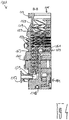
- turbomolecular pump 111 comprises a pump inlet 115 surrounded by an inlet flange 113, to which in a conventional manner, a non-illustrated recipient can be connected.
- the gas from the recipient may be drawn from the recipient via the pump inlet 115 and conveyed through the pump to a pump outlet 117 to which a backing pump, such as a rotary vane pump, may be connected.
- the inlet flange 113 forms according to the orientation of the vacuum pump Fig. 1 the upper end of the housing 119 of the vacuum pump 111.
- the housing 119 comprises a lower part 121, on which an electronics housing 123 is arranged laterally.
- Housed in the electronics housing 123 are electrical and / or electronic components of the vacuum pump 111, eg for operating an electric motor 125 arranged in the vacuum pump.
- a plurality of connections 127 for accessories are provided on the electronics housing 123.
- a data interface 129 for example, according to the RS485 standard, and a power supply terminal 131 on the electronics housing 123 are arranged.
- a flood inlet 133 On the housing 119 of the turbomolecular pump 111, a flood inlet 133, in particular in the form of a flood valve, is provided, via which the vacuum pump 111 can be flooded.
- a sealing gas connection 135, which is also referred to as flushing gas connection is furthermore arranged, via which flushing gas for protecting the electric motor 125 (see, for example, US Pat Fig. 3 ) can be brought before the pumped by the pump gas in the engine compartment 137, in which the electric motor 125 is housed in the vacuum pump 111.
- two coolant connections 139 are further arranged, wherein one of the coolant connections as inlet and the other coolant connection as Outlet for coolant is provided, which can be passed for cooling purposes in the vacuum pump.
- the lower side 141 of the vacuum pump can serve as a base, so that the vacuum pump 111 can be operated standing on the bottom 141.
- the vacuum pump 111 can also be fastened to a recipient via the inlet flange 113 and thus be operated to a certain extent suspended.
- the vacuum pump 111 can be designed so that it can also be put into operation, if it is aligned differently than in Fig. 1 is shown.
- Embodiments of the vacuum pump can also be implemented in which the lower side 141 can not be turned down but can be turned to the side or directed upwards.
- a bearing cap 145 is attached to the bottom 141.
- mounting holes 147 are arranged, via which the pump 111 can be attached, for example, to a support surface.
- a coolant line 148 is shown, in which the coolant introduced and discharged via the coolant connections 139 can circulate.
- the vacuum pump comprises a plurality of process gas pumping stages for conveying the process gas pending at the pump inlet 115 to the pump outlet 117.
- a rotatable relative to a stator 150 rotor 149 is arranged, which has a rotatable about a rotation axis 151 rotor shaft 153.
- Turbomolecular pump 111 includes a plurality of turbomolecular pump stages operatively connected in series with a plurality of rotor disks 155 mounted on rotor shaft 153 and stator disks 157 disposed between rotor disks 155 and housed in housing 119.
- a rotor disk 155 and an adjacent stator disk 157 each form a turbomolecular one pump stage.
- the stator disks 157 are held by spacer rings 159 at a desired axial distance from each other.
- the vacuum pump further comprises Holweck pumping stages which are arranged one inside the other in the radial direction and which are pumpingly connected to one another in series.
- the rotor of the Holweck pump stages comprises a rotor hub 161 arranged on the rotor shaft 153 and two cylinder shell-shaped Holweck rotor sleeves 163, 165 fastened to the rotor hub 161 and oriented coaxially with the rotation axis 151 and nested in the radial direction.
- two cylinder jacket-shaped Holweck stator sleeves 167, 169 are provided, which are also oriented coaxially to the rotation axis 151 and, as seen in the radial direction, are nested one inside the other.
- the pump-active surfaces of the Holweck pump stages are formed by the lateral surfaces, ie by the radial inner and / or outer surfaces, the Holweck rotor sleeves 163, 165 and the Holweck stator sleeves 167, 169.
- the radially inner surface of the outer Holweck stator sleeve 167 faces the radially outer surface of the outer Holweck rotor sleeve 163, forming a radial Holweck gap 171, and forms with it the first Holweck pump stage subsequent to the turbomolecular pumps.
- the radially inner surface of the outer Holweck rotor sleeve 163 faces the radially outer surface of the inner Holweck stator sleeve 169 to form a radial Holweck gap 173 and forms with this is a second Holweck pumping stage.
- the radially inner surface of the inner Holweck stator sleeve 169 faces the radially outer surface of the inner Holweck rotor sleeve 165 to form a radial Holweck gap 175 and forms with this the third Holweck pumping stage.
- a radially extending channel may be provided, via which the radially outer Holweck gap 171 is connected to the middle Holweck gap 173.
- a radially extending channel may be provided, via which the middle Holweck gap 173 is connected to the radially inner Holweck gap 175.
- a connecting channel 179 to the outlet 117 may be provided at the lower end of the radially inner Holweck rotor sleeve 165.
- the above-mentioned pump-active surfaces of the Holweck stator sleeves 163, 165 each have a plurality of Holweck grooves running around the axis of rotation 151 in the axial direction, while the opposite lateral surfaces of the Holweck rotor sleeves 163, 165 are smooth and the gas for operating the Drive vacuum pump 111 in the Holweck grooves.
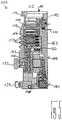
- a roller bearing 181 in the region of the pump outlet 117 and a permanent magnet bearing 183 in the region of the pump inlet 115 are provided.
- an inventive permanent magnet bearing 10 may be provided, as will be described below.
- a conical spray nut 185 with an outer diameter increasing toward the rolling bearing 181 is provided on the rotor shaft 153.
- the spray nut 185 is at least one scraper one Operating equipment in sliding contact.
- the resource storage comprises a plurality of absorbent discs 187 stacked on top of each other and impregnated with a rolling bearing bearing means 181, eg with a lubricant.
- the operating medium is transferred by capillary action of the resource storage on the scraper on the rotating sprayer nut 185 and promoted in the direction of increasing outer diameter of the spray nut 185 to the roller bearing 181 through where the centrifugal force along the spray nut 185 eg fulfills a lubricating function.
- the rolling bearing 181 and the resource storage are enclosed by a trough-shaped insert 189 and the bearing cap 145 in the vacuum pump.
- the permanent magnet bearing 183 includes a rotor-side bearing half 191 and a stator-side bearing half 193, each comprising a ring stack of a plurality of stacked in the axial direction of permanent magnetic rings 195, 197 include.
- the ring magnets 195, 197 are opposed to each other to form a radial bearing gap 199, wherein the rotor-side ring magnets 195 are disposed radially outward and the stator-side ring magnets 197 radially inward.
- the magnetic field present in the bearing gap 199 causes magnetic repulsive forces between the ring magnets 195, 197, which cause a radial bearing of the rotor shaft 153.
- the rotor-side ring magnets 195 are supported by a carrier section 201 of the rotor shaft 153, which surrounds the ring magnets 195 radially on the outside.
- the stator-side ring magnets 197 are supported by a stator-side support portion 203, which extends through the ring magnets 197 and is suspended on radial struts 205 of the housing 119.
- Parallel to the axis of rotation 151, the rotor-side ring magnets 195 are fixed by a lid element 207 coupled to the carrier section 203.
- the stator-side ring magnets 197 are parallel to the axis of rotation 151 in one direction by a fastening ring 209 connected to the carrier section 203 and one connected to the carrier section 203 Fixing ring 211 fixed. Between the fastening ring 211 and the ring magnet 197, a plate spring 213 may also be provided.
- an emergency or catch bearing 215 is provided, which runs empty during normal operation of the vacuum pump 111 without contact and only with an excessive radial deflection of the rotor 149 relative to the stator 150 engages to a radial stop for the rotor 149, since a collision of the rotor-side structures with the stator-side structures is prevented.
- the safety bearing 215 is designed as an unlubricated rolling bearing and forms with the rotor 149 and / or the stator 150 has a radial gap, which causes the safety bearing 215 is disengaged in the normal pumping operation.
- the radial deflection at which the safety bearing 215 engages is sized large enough so that the safety bearing 215 does not engage during normal operation of the vacuum pump, and at the same time small enough so that a collision of the rotor-side structures with the stator-side structures is prevented in all circumstances.
- the vacuum pump 111 includes the electric motor 125 for rotationally driving the rotor 149.
- the armature of the electric motor 125 is formed by the rotor 149 whose rotor shaft 153 extends through the motor stator 217.
- On the extending through the motor stator 217 through portion of the rotor shaft 153 may be arranged radially outside or embedded a permanent magnet arrangement.
- a gap 219 is arranged, which comprises a radial motor gap, via which the motor stator 217 and the permanent magnet arrangement for the transmission of the drive torque can influence magnetically.
- the motor stator 217 is fixed in the housing within the motor space 137 provided for the electric motor 125.
- a sealing gas which is also referred to as purge gas, and which may be, for example, air or nitrogen, enter the engine compartment 137.
- the electric motor 125 can be provided with process gas, e.g. against corrosive fractions of the process gas.
- the engine compartment 137 may also be evacuated via the pump outlet 117, i. In the engine compartment 137, at least approximately, the vacuum pressure caused by the backing pump connected to the pump outlet 117 prevails.
- delimiting wall 221 Between the rotor hub 161 and a motor space 137 delimiting wall 221 may also be a so-called. And per se known labyrinth seal 223 may be provided, in particular to achieve a better seal of the engine compartment 217 against the Holweck pump stages located radially outside.
- Fig. 6 shows a cross-sectional view of a permanent magnet bearing 10 according to the invention according to a first embodiment, which can be used in functional terms instead of the permanent magnet bearing 183 of the turbomolecular pump 111.
- the permanent magnet bearing 10 comprises two successive pairs 12 of hollow cylindrical monolithic permanent magnets 14a, 14b (hereinafter referred to as permanent magnets 14a, 14b) in the direction of a rotation axis D of the permanent magnet bearing 10. It will be appreciated that the permanent magnet bearing 10 may comprise only a pair 12 of permanent magnets 14a, 14b or more than two pairs 12 of permanent magnets 14a, 14b, as indicated by the continuation points continuing in the axial direction.
- the two axially successive permanent magnets 14a can rotor side, ie, attached to the rotor 149 of the turbomolecular pump 111 be.
- the two monolithic permanent magnets 14b are arranged, which may be mounted on the stator 150 of the turbomolecular pump 111 on the stator side.
- the two rotor-side permanent magnets 14a are arranged rotatable relative to the two stator-side permanent magnets 14b with respect to the rotation axis D of the magnetic bearing 10. It is understood that in a corresponding embodiment of the turbomolecular pump 111 and the other way around the stator-side permanent magnets 14b could be arranged radially outside of the rotor-side permanent magnets 14a.
- the rotor-side and stator-side permanent magnets 14a, 14b each have a longitudinal axis L.
- the longitudinal axes L of the rotor-side and stator-side permanent magnets 14a, 14b coincide with the axis of rotation D of the permanent magnet bearing 10.
- each of the permanent magnets 14a, 14b of the permanent magnet bearing 10 has a plurality of axially arranged and at least approximately axially magnetized sections 16, 16 ', the magnetizations of which are aligned alternately opposite to each other, which in Fig. 6 to 8 is indicated by alternately oppositely aligned vector arrows P, P '.
- the axial dimensions of the two end portions 16 'of a respective permanent magnet 14a, 14b differ from the axial dimensions of the portions 16 adjacent to the end portions 16'. Concretely, the axial dimensions of the end portions 16 'are one-half lower than those of FIGS On the other hand, the axial dimensions of all other sections 16 of each permanent magnet 14a, 14b arranged between the two end sections 16 'are at least approximately equal.
- the sections 16, 16 typically have a width of 1 to 10 mm, preferably 2 to 9 mm and particularly preferably 3 to 8 mm.
- pairs of permanent magnets 14a, 14b adjacent end portions 16 'of the successive permanent magnets 14a, 14b each have rectified magnetizations.
- the respective adjacent half end portions 16 ' together have an axial dimension which corresponds to that of one of the adjacent portions 16.
- the advantage of such an arrangement of two pairs 12 of permanent magnets 14a, 14b is that the pairs 12 of permanent magnets 14a, 14b are characterized by both the small stray magnetic field of each individual permanent magnet 14a, 14b and the rectified magnetization of the adjacent end portions 16 '.
- axially successive permanent magnets 14a, 14b particularly well, that is stack with low stacking tolerances, one above the other.
- Fig. 7 shows a permanent magnet bearing according to the invention 10 according to a second embodiment, which differs from the permanent magnet bearing 10 according to the first embodiment in that adjacent end portions 16 'of the successive in the direction of the axis of rotation D of the permanent magnet bearing 10 permanent magnets 14a, 14b each have opposite magnetizations. Since the radial rigidity of a permanent magnet bearing 10 is increased by the number of oppositely magnetized portions per unit length, the arrangement of the pairs 12 of permanent magnets 14a, 14b in the permanent magnet bearing 10 according to the second embodiment has the advantage that it compares to the permanent magnet bearing 10 according to the first embodiment has a higher radial bearing stiffness.
- Fig. 8 shows a cross-sectional view of an arrangement which can be used for producing a monolithic permanent magnet 14 according to the invention from a body 18 of magnetizable material. It is in Fig. 8 only one half of the permanent magnet 14 and the body 18 is shown, wherein one can imagine the other half due to the rotationally symmetrical configuration of the hollow cylindrical permanent magnet 14 and body 18 on the left side of the longitudinal axis L of the permanent magnet 14 and body 18.
- the body 18 may for example consist of iron, a ferrimagnetic ceramic (ferrites) or a magnetizable plastic.
- magnetizable materials comprising rare earth metals are used, such as samarium cobalt (SmCo) or neodymium iron boron (NdFeB).
- the body 18 can be produced by sintering the magnetizable materials.
- the assembly includes an inner coil 20 and an outer coil 22, with the inner coil 20 disposed radially inwardly of the body 18 and the outer coil 22 radially outward of the body.
- Both coils 20, 22 comprise a plurality of axially successive windings 24, wherein the windings 24 of the inner Spool 20 and the windings 24 of the outer coil 22 seen in the direction of the longitudinal axis L of the body 18 are at least approximately arranged at the same height. Based on Fig. 8 It can be seen that in each case a pair of windings 24 arranged at the same height projects axially at axial ends of the body 18.
- the windings 24 have a rectangular conductor cross section with a radial dimension b and an axial dimension h, wherein the windings are separated in the axial direction by the distance d from each other. According to a preferred embodiment, at least one of the windings 24 of the inner coil 20 and / or the outer coil 22 can be controlled separately from the other windings.
- a hollow cylindrical body 18 of magnetizable material is disposed between the inner coil 20 and outer coil 22 such that each pair of equiangularly wound coils 24 axially projects beyond the axial ends of the body 18.
- a voltage is applied to the coils 20, 22 for generating a current flow through the windings 24 such that the resulting current flow through the windings 24 of the inner and outer coils 20, 22 is directed opposite.
- a monolithic hollow-cylindrical permanent magnet 14 is formed from the body 18.
- the permanent magnet 14 can also be produced from a body 18 of magnetizable material designed as a solid cylinder, it being understood that the arrangement of an inner coil 20 in the interior of the magnetizable body 18 is then omitted.
Abstract
Die Erfindung betrifft einen monolithischer Permanentmagnet, insbesondere für ein Permanentmagnetlager einer Vakuumpumpe, mit einer Längsachse sowie mehreren entlang dieser angeordneten und zumindest annähernd axial magnetisierten Abschnitten, deren Magnetisierungen jeweils alternierend entgegengesetzt zueinander ausgerichtet sind, dadurch gekennzeichnet, dass sich die axiale Abmessung und/oder die Magnetisierung wenigstens eines magnetisierten Abschnitts und die axiale Abmessung und/oder die Magnetisierung wenigstens eines anderen magnetisierten Abschnitts unterscheiden.The invention relates to a monolithic permanent magnet, in particular for a permanent magnet bearing of a vacuum pump, with a longitudinal axis and a plurality of arranged along this and at least approximately axially magnetized sections whose magnetizations are each oriented alternately opposite to each other, characterized in that the axial dimension and / or Magnetization of at least one magnetized portion and the axial dimension and / or the magnetization of at least one other magnetized portion differ.
Description
Die vorliegende Erfindung betrifft einen monolithischen Permanentmagneten, insbesondere für ein Permanentmagnetlager einer Vakuumpumpe, mit einer Längsachse sowie mehreren entlang dieser angeordneten und zumindest annähernd axial magnetisierten Abschnitten, deren Magnetisierungen jeweils alternierend entgegengesetzt zueinander ausgerichtet sind.The present invention relates to a monolithic permanent magnet, in particular for a permanent magnet bearing of a vacuum pump, having a longitudinal axis and a plurality of arranged along this and at least approximately axially magnetized sections whose magnetizations are each aligned alternately opposite to each other.
Monolithische Permanentmagnete sind grundsätzlich bekannt und dienen beispielsweise in Vakuumpumpen, insbesondere in Turbomolekularpumpen, zur schmiermittelfreien Lagerung eines in Bezug auf einen Stator drehbaren Rotors. Hierbei weisen sowohl der Stator als auch der Rotor jeweils mindestens einen monolithischen Permanentmagneten auf, welche zusammen ein Permanentmagnetlager bilden.Monolithic permanent magnets are known in principle and are used, for example, in vacuum pumps, in particular in turbomolecular pumps, for lubricant-free mounting of a rotor rotatable with respect to a stator. Here, both the stator and the rotor each have at least one monolithic permanent magnet, which together form a permanent magnet bearing.
An den axialen Enden eines monolithischen Permanentmagneten treten magnetische Flusslinien aus dem monolithischen Permanentmagneten aus, wodurch ein magnetisches Streufeld entsteht. Das magnetische Streufeld kann hochempfindliche Anwendungen beeinträchtigen, z.B. indem es infolge der Lorentzkraft einen Elektronenstrahl eines Elektronenmikroskops ablenkt, wodurch Abbildungsfehler hervorgerufen werden können. Auch kann das magnetische Streufeld die Magnetisierung einer unter Vakuum abgeschiedenen hochempfindlichen magnetischen Dünnschicht beeinflussen. Es besteht daher ein Bedarf an monolithischen Permanentmagneten mit einem geringen magnetischen Streufeld.Magnetic flux lines emerge from the monolithic permanent magnet at the axial ends of a monolithic permanent magnet, resulting in a stray magnetic field. The stray magnetic field can affect high-sensitivity applications, for example by deflecting an electron beam of an electron microscope due to the Lorentz force, which can cause aberrations. Also, the stray magnetic field may affect the magnetization of a vacuum-deposited high-sensitivity magnetic thin film. There is therefore a need for monolithic permanent magnets with a low stray magnetic field.
Es ist daher eine Aufgabe der Erfindung, einen monolithischen Permanentmagneten zu schaffen, welcher für hochempfindliche Anwendungen besser geeignet ist.It is therefore an object of the invention to provide a monolithic permanent magnet which is more suitable for high sensitivity applications.
Die Aufgabe wird durch einen monolithischen Permanentmagneten mit den Merkmalen des Anspruchs 1 gelöst und insbesondere dadurch, dass sich die axiale Abmessung und/oder die Magnetisierung wenigstens eines magnetisierten Abschnitts und die axiale Abmessung und/oder die Magnetisierung wenigstens eines anderen magnetisierten Abschnitts unterscheiden.The object is achieved by a monolithic permanent magnet having the features of
Der Erfindung liegt die Erkenntnis zugrunde, dass sich das magnetische Streufeld eines monolithischen Permanentmagneten verringert, wenn sich die axiale Abmessung und/oder Magnetisierung wenigstens eines magnetisierten Abschnitts von der axialen Abmessung und/oder Magnetisierung wenigstens eines anderen magnetisierten Abschnitts unterscheidet bzw. unterscheiden. Aus der Verringerung des magnetischen Streufeldes ergibt sich der Vorteil, dass sich der monolithische Permanentmagnet bei Anwendungen verwenden lässt, bei welchen ein geringes magnetisches Streufeld unerlässlich ist, wie zum Beispiel in Lagern von Vakuumpumpen, welche zur Evakuierung von Elektronenmikroskopen dienen. Dabei ist die Verwendung des erfindungsgemäßen monolithischen Permanentmagneten nicht auf die Anwendung in Vakuumpumpen beschränkt. Es ist auch denkbar, dass ein erfindungsgemäßer monolithischer Permanentmagnet überall dort eingesetzt werden kann, wo geringe magnetische Streufelder wünschenswert sind, wie z.B. in Audioverstärkern.The invention is based on the finding that the stray magnetic field of a monolithic permanent magnet decreases when the axial dimension and / or magnetization of at least one magnetized section differ from the axial dimension and / or magnetization of at least one other magnetized section. The advantage of reducing stray magnetic field is that the monolithic permanent magnet can be used in applications where low stray magnetic field is indispensable, such as vacuum pump bearings used to evacuate electron microscopes. The use of the monolithic permanent magnet according to the invention is not limited to use in vacuum pumps. It is also conceivable that a monolithic permanent magnet according to the invention can be used wherever small stray magnetic fields are desirable, e.g. in audio amplifiers.
Unter Magnetisierung eines magnetisierten Abschnitts wird hier die magnetische Remanenz verstanden, welche der magnetisierte Abschnitt beibehält, nachdem das zum Aufmagnetisieren, d.h. zum Erreichen der Magnetisierung, benötigte externe Magnetfeld deaktiviert wurde.Magnetization of a magnetized section is understood here as meaning the magnetic remanence which the magnetized section retains after the external magnetic field required for magnetizing, ie for achieving the magnetization, has been deactivated.
Bei einem monolithischen Permanentmagneten handelt es sich, anders als bei einem durch mehrere aufeinandergestapelte Einzelmagnete gebildeten Magnetstapel, um einen aus einem Stück gefertigten Magneten. Die einzelnen Abschnitte des monolithischen Permanentmagneten sind daher visuell nicht als solche zu erkennen, sondern unterscheiden sich nur bezüglich ihrer jeweiligen Magnetisierungsausrichtung.A monolithic permanent magnet, unlike a magnetic stack formed by a plurality of stacked individual magnets, is a one-piece magnet. The individual sections of the monolithic permanent magnet are therefore not visually recognizable as such, but differ only in their respective magnetization orientation.
Jeder magnetisierte Abschnitt weist einen magnetischen Nord- und Süd-Pol auf, wobei konventionsgemäß die Ausrichtung der Magnetisierung durch einen im Inneren des magnetisierten Abschnitts vom Süd-Pol ausgehenden und am Nord-Pol endenden Vektorpfeil definiert ist.Each magnetized section has a magnetic north and south pole, conventionally the orientation of the magnetization being defined by a vector arrow originating in the interior of the magnetized section from the south pole and terminating at the north pole.
Bei mehreren zumindest annähernd axial magnetisierten Abschnitten, deren Magnetisierungen jeweils alternierend entgegengesetzt zueinander ausgerichtet sind, grenzen jeweils dieselben magnetischen Pole an der Grenze zwischen zwei benachbarten Abschnitten aneinander.In the case of a plurality of at least approximately axially magnetized sections, the magnetizations of which are respectively aligned alternately opposite to one another, in each case the same magnetic poles adjoin one another at the boundary between two adjacent sections.
Wie bereits erwähnt sind die jeweiligen magnetisierten Abschnitte des monolithischen Permanentmagneten zumindest annähernd in axialer Richtung magnetisiert. Dies bedeutet, dass die Magnetisierungsausrichtung eines magnetisierten Abschnitts zumindest annähernd parallel zur Längsachse des monolithischen Permanentmagneten ausgerichtet ist.As already mentioned, the respective magnetized sections of the monolithic permanent magnet are magnetized at least approximately in the axial direction. This means that the magnetization orientation of a magnetized section is aligned at least approximately parallel to the longitudinal axis of the monolithic permanent magnet.
Der monolithische Permanentmagnet besteht vorzugsweise aus einem magnetisierbaren Material, wie z.B aus Eisen, einer ferrimagnetischen Keramik (Ferrite) oder einem magnetisierbaren Kunststoff. Bevorzugt können auch magnetisierbare Materialien verwendet werden, welche Seltenerdmetalle umfassen, wie zum Beispiel Samarium-Cobalt (SmCo) oder Neodym-Eisen-Bor (NdFeB). Die magnetisierbaren Materialien lassen sich beispielsweise durch ein Sinterverfahren fügen.The monolithic permanent magnet is preferably made of a magnetizable material, such as iron, a ferrimagnetic ceramic (ferrites) or a magnetizable plastic. It is also possible to use magnetizable materials which comprise rare earth metals, for example samarium cobalt (SmCo) or neodymium-iron-boron (NdFeB). The magnetizable materials can be added, for example, by a sintering process.
Ein monolithischer Permanentmagnet kann eine Gesamtlänge zwischen 15 und 25 mm, vorzugsweise zwischen 17 und 23 mm und besonders bevorzugt zwischen 19 und 21 mm aufweisen. Die Breite eines Abschnitts kann zwischen 1 und 10 mm, vorzugsweise zwischen 2 und 9 mm und besonders bevorzugt zwischen 3 und 8 mm liegen.A monolithic permanent magnet may have an overall length of between 15 and 25 mm, preferably between 17 and 23 mm, and more preferably between 19 and 21 mm. The width of a section may be between 1 and 10 mm, preferably between 2 and 9 mm and more preferably between 3 and 8 mm.
Vorteilhafte Ausbildungen der Erfindung sind den Unteransprüchen, der Beschreibung und den Zeichnungen zu entnehmen.Advantageous embodiments of the invention are described in the dependent claims, the description and the drawings.
Beispielsweise kann die axiale Abmessung und/oder Magnetisierung des wenigstens einen magnetisierten Abschnitts geringer, insbesondere um die Hälfte geringer, sein als die axiale Abmessung und/oder Magnetisierung des anderen magnetisierten Abschnitts.For example, the axial dimension and / or magnetization of the at least one magnetized section can be smaller, in particular smaller by half, than the axial dimension and / or magnetization of the other magnetized section.
Eine besonders starke Verringerung des magnetischen Streufeldes lässt sich erreichen, wenn sich die axiale Abmessung und/oder Magnetisierung eines oder jedes Endabschnitts und die axiale Abmessung und/oder Magnetisierung eines zu dem oder jedem Endabschnitt benachbarten magnetisierten Abschnitts unterscheiden. Idealerweise ist bzw. sind die axiale Abmessung und/oder Magnetisierung des oder jedes Endabschnitts zumindest annähernd um die Hälfte geringer als die des benachbarten Abschnitts. Es versteht sich, dass die axiale Abmessung und/oder Magnetisierung des oder jedes Endabschnitts grundsätzlich auch um einen anderen Bruchteil als die Hälfte geringer sein kann bzw. können als die des benachbarten Abschnitts, wie z.B. um ein Drittel, zwei Drittel, ein Viertel oder beliebige andere Bruchteile. Ferner ist auch denkbar, dass mindestens ein magnetisierter Abschnitt eine größere axiale Abmessung und/oder stärkere Magnetisierung aufweist, als die eines benachbarten Abschnitts.A particularly large reduction of the stray magnetic field can be achieved if the axial dimension and / or magnetization of one or each end portion and the axial dimension and / or magnetization of a magnetized portion adjacent to the or each end portion differ. Ideally, the axial dimension and / or magnetization of the or each end portion is at least approximately one-half less than that of the adjacent portion. It will be understood that the axial dimension and / or magnetization of the or each end portion may in principle be less than that of the adjacent portion, e.g. by one-third, two-thirds, one-fourth or any other fraction. Furthermore, it is also conceivable that at least one magnetized section has a larger axial dimension and / or stronger magnetization than that of an adjacent section.
Bevorzugt sind die axialen Abmessungen und/oder Magnetisierungen aller zwischen zwei Endabschnitten angeordneten Abschnitte des monolithischen Permanentmagnets zumindest annähernd gleich groß. Dies schließt ein, dass ein Endabschnitt zumindest annähernd die gleiche axiale Abmessung und/oder Magnetisierung aufweist, wie alle anderen zwischen den Endabschnitten angeordneten Abschnitte.The axial dimensions and / or magnetizations of all sections of the monolithic permanent magnet arranged between two end sections are preferred at least approximately the same size. This implies that one end portion has at least approximately the same axial dimension and / or magnetization as all other portions disposed between the end portions.
Grundsätzlich ist es aber auch denkbar, dass nicht nur der oder jeder Endabschnitt eine unterschiedliche axiale Abmessung und/oder Magnetisierung zu dem oder jedem Endabschnitt benachbarten magnetisierten Abschnitt aufweist, sondern dass auch die zu dem oder jedem Endabschnitt benachbarten Abschnitte eine unterschiedliche axiale Abmessung und/oder Magnetisierung zu sowohl dem oder jedem Endabschnitt als auch zu dem oder jedem Abschnitt, welcher dem oder jedem Endabschnitt in axialer Richtung gesehen gegenüberliegt. Anders ausgedrückt können sich die axialen Abmessungen und/oder Magnetisierungen der magnetisierten Abschnitte ausgehend von dem oder jedem Endabschnitt in axialer Richtung gesehen zur Mitte des monolithischen Permanentmagneten hin von Abschnitt zu Abschnitt ändern, vorzugsweise zunehmen, insbesondere sukzessiv zunehmen.In principle, however, it is also conceivable that not only the or each end portion has a different axial dimension and / or magnetization to the or each end portion adjacent magnetized portion, but that the adjacent to the or each end portion sections a different axial dimension and / or Magnetization to both the or each end portion and to the or each portion which faces the or each end portion in the axial direction. In other words, the axial dimensions and / or magnetizations of the magnetized sections starting from the or each end section in the axial direction can change from section to section towards the center of the monolithic permanent magnet, preferably increase, in particular increase successively.
Bevorzugt sind alle magnetisierten Abschnitte des monolithischen Permanentmagnets magnetisch gesättigt, d.h. die magnetisierten Abschnitte weisen zumindest annähernd einen maximal erreichbaren Sättigungswert der Magnetisierung auf. An dieser Stelle ist hervorzuheben, dass auch der oder jeder magnetisierte Endabschnitt magnetisch gesättigt sein kann, insbesondere wenn die axiale Abmessung des oder jedes Endabschnitts geringer ist als die des benachbarten Abschnitts. Es ist aber auch denkbar, dass alle magnetisierten Abschnitte des monolithischen Permanentmagneten zumindest annähernd gleiche axiale Abmessungen aufweisen, und mindestens ein magnetisierter Endabschnitt unterschiedlich, insbesondere geringer, magnetisiert ist als ein zu dem mindestens einen Endabschnitt benachbarter Abschnitt. Ferner ist vorstellbar, dass mindestens ein magnetisierter Endabschnitt sowohl eine unterschiedliche, insbesondere geringere, axiale Abmessung als auch eine unterschiedliche, insbesondere geringere, Magnetisierung aufweisen kann als ein zu dem mindestens einen Endabschnitt benachbarter magnetisierter Abschnitt.Preferably, all magnetized sections of the monolithic permanent magnet are magnetically saturated, ie the magnetized sections have at least approximately a maximum achievable saturation value of the magnetization. At this point, it should be emphasized that also the or each magnetized end portion may be magnetically saturated, in particular when the axial dimension of the or each end portion is less than that of the adjacent portion. However, it is also conceivable that all magnetized sections of the monolithic permanent magnet have at least approximately the same axial dimensions, and at least one magnetized end section is different, in particular less, magnetized than a section adjacent to the at least one end section. Furthermore, it is conceivable that at least one magnetized end section both a different, in particular smaller, axial Dimension as well as a different, in particular lower, magnetization may have as a to the at least one end portion adjacent magnetized portion.
Es versteht sich, dass zwischen den magnetisch gesättigten Abschnitten Bereiche vorliegen, in welchen sich die Magnetisierungsausrichtung ändert, so dass hier eine magnetische Sättigung geringer ist als in den magnetisierten Abschnitten.It is understood that there are areas between the magnetically saturated portions in which the magnetization orientation changes, so that a magnetic saturation is lower than in the magnetized portions.
Überraschenderweise konnte gezeigt werden, dass sich das magnetische Streufeld eines monolithischen Permanentmagneten besonders stark reduzieren lässt, wenn dieser eine ungerade Anzahl magnetisierter Abschnitte aufweist.Surprisingly, it has been shown that the stray magnetic field of a monolithic permanent magnet can be reduced particularly strongly if it has an odd number of magnetized sections.
Gemäß einer vorteilhaften Ausgestaltung ist der monolithische Permanentmagnet hohlzylindrisch ausgebildet. Es versteht sich, dass der monolithische Permanentmagnet aber auch als ein massiver Zylinder ausgebildet sein kann. Grundsätzlich kann der monolithische Permanentmagnet auch eine beliebige andere prismatische Form, z.B. die eines Quaders, aufweisen.According to an advantageous embodiment, the monolithic permanent magnet is formed as a hollow cylinder. It is understood that the monolithic permanent magnet can also be designed as a solid cylinder. In principle, the monolithic permanent magnet can also be any other prismatic form, e.g. that of a cuboid, have.
Die Erfindung ist auch auf ein Permanentmagnetlager, insbesondere für eine Vakuumpumpe, mit einem Paar von monolithischen Permanentmagneten gerichtet, wobei der eine Permanentmagnet relativ zu dem anderen Permanentmagneten um eine zu den Längsachsen der Permanentmagnete zumindest annähernd parallele Drehachse drehbar gelagert ist. Dabei ist einer der Permanentmagneten radial innerhalb des anderen Permanentmagneten derart angeordnet, dass sich radial benachbarte Abschnitte des äußeren und inneren monolithischen Permanentmagneten in Richtung der Drehachse gesehen zumindest annähernd auf gleicher Höhe befinden. Des Weiteren sind die Magnetisierungen der radial benachbarten Abschnitte des äußeren und inneren monolithischen Permanentmagneten zumindest annähernd gleichgerichtet.The invention is also directed to a permanent magnet bearing, in particular for a vacuum pump, with a pair of monolithic permanent magnets, wherein the one permanent magnet is rotatably mounted relative to the other permanent magnet about an axis of rotation at least approximately parallel to the longitudinal axes of the permanent magnets. In this case, one of the permanent magnets is arranged radially within the other permanent magnet such that radially adjacent portions of the outer and inner monolithic permanent magnets are at least approximately at the same height seen in the direction of the axis of rotation. Furthermore, the magnetizations of the radially adjacent portions of the outer and inner monolithic permanent magnets are at least approximately rectified.
Die Längsachsen der Permanentmagnete und die Drehachse des Permanentmagnetlagers sind bevorzugt parallel zueinander ausgerichtet. Insbesondere können die Längsachsen der Permanentmagnete und die Drehachse des Permanentmagnetlagers zusammenfallen.The longitudinal axes of the permanent magnets and the axis of rotation of the permanent magnet bearing are preferably aligned parallel to one another. In particular, the longitudinal axes of the permanent magnets and the axis of rotation of the permanent magnet bearing can coincide.
Die radiale Steifigkeit des Permanentmagnetlagers lässt sich deutlich erhöhen, wenn das Permanentmagnetlager aus mindestens zwei in Richtung der Drehachse gesehen aufeinanderfolgende Paare von monolithischen Permanentmagneten gebildet ist und angrenzende Abschnitte der aufeinanderfolgenden Permanentmagnete jeweils entgegengesetzte Magnetisierungen aufweisen.The radial stiffness of the permanent magnet bearing can be increased significantly if the permanent magnet bearing is formed from at least two successive pairs of monolithic permanent magnets viewed in the direction of the rotation axis and adjacent sections of the successive permanent magnets each have opposite magnetizations.
Das Permanentmagnetlager kann sowohl ausschließlich monolithische Permanentmagnete umfassen als auch eine Kombination aus einem oder mehreren monolithischen Permanentmagneten und einem oder mehreren Einzelmagneten oder auch eine Kombination mehrerer Einzelmagnete, wovon mindestens einer sich in der axialen Abmessung und/oder Magnetisierung von den restlichen unterscheidet.The permanent magnet bearing may comprise both monolithic permanent magnets and a combination of one or more monolithic permanent magnets and one or more individual magnets or a combination of a plurality of individual magnets, at least one of which differs from the rest in axial dimension and / or magnetization.
Vorteilhafterweise sind die Permanentmagnete des oder jedes Paares von Permanentmagneten hohlzylindrisch ausgebildet. Umfasst das Permanentmagnetlager auch Einzelmagnete, so können diese als Ringmagnete ausgebildet sein.Advantageously, the permanent magnets of the or each pair of permanent magnets are hollow-cylindrical. If the permanent magnet bearing also includes individual magnets, these may be designed as ring magnets.
Die Erfindung betrifft auch eine Vakuumpumpe, insbesondere Turbomolekularpumpe, mit einem Rotor und einem Stator und einem Permanentmagnetlager, wobei der eine monolithische Permanentmagnet rotorseitig und der andere monolithische Permanentmagnet statorseitig angeordnet ist. Es ist dabei unerheblich, ob der Rotor innerhalb des Stators oder andersherum der Stator innerhalb des Rotors angeordnet ist.The invention also relates to a vacuum pump, in particular turbomolecular pump, with a rotor and a stator and a permanent magnet bearing, wherein the one monolithic permanent magnet on the rotor side and the other monolithic permanent magnet is arranged on the stator side. It is irrelevant whether the rotor is arranged inside the stator or vice versa, the stator within the rotor.
Weiterer Gegenstand der Erfindung ist ein Verfahren zur Herstellung eines monolithischen Permanentmagneten. Das Verfahren umfasst folgende Schritte: Bereitstellen eines Körpers aus magnetisierbarem Material, welcher eine Längsachse definiert, Anordnen des Körpers im Inneren einer den Körper umgebenden äußeren Spule mit mehreren axial aufeinanderfolgenden Wicklungen und Anlegen einer Spannung an die Spule zur Erzeugung eines Stromflusses durch die Wicklungen derart, dass der resultierende Stromfluss in axial aufeinanderfolgenden Wicklungen entgegengesetzt gerichtet ist, um durch das dadurch hervorgerufene Magnetfeld einen monolithischen Permanentmagneten aus dem Körper zu bilden.Another object of the invention is a method for producing a monolithic permanent magnet. The method comprises the following steps: providing a body of magnetizable material defining a longitudinal axis, arranging the body in the interior of an outer coil surrounding the body with a plurality of axially successive windings and applying a voltage to the coil to generate a current flow through the windings such that the resulting current flow is directed in opposite directions in axially successive windings in order to form a monolithic permanent magnet out of the body by the magnetic field thereby caused.
Ist der Körper hohlzylindrisch, so kann das Verfahren zusätzlich die Schritte umfassen: Bereitstellen eines hohlzylindrischen Körpers aus magnetisierbarem Material, welcher eine Längsachse definiert, zusätzliches Anordnen einer inneren Spule mit mehreren axial aufeinanderfolgenden Wicklungen im Inneren des Körpers, wobei die Wicklungen der inneren Spule und der äußeren Spule in Richtung der Längsachse des Körpers gesehen zumindest annähernd auf gleicher Höhe angeordnet sind und Anlegen einer Spannung zur Erzeugung eines Stromflusses durch die Wicklungen der inneren und der äußeren Spule derart, dass der resultierende Stromfluss durch die Wicklungen der inneren und äußeren Spule entgegengesetzt gerichtet ist, um durch das zwischen den inneren und äußeren Wicklungen hervorgerufene Magnetfeld einen monolithischen hohlzylinderförmigen Permanentmagneten aus dem Körper zu bilden.If the body is hollow cylindrical, the method may additionally include the steps of: providing a hollow cylindrical body of magnetizable material defining a longitudinal axis, additionally disposing an inner coil having a plurality of axially consecutive windings inside the body, the windings of the inner coil and the inner coil outer coil disposed in the direction of the longitudinal axis of the body at least approximately at the same height and applying a voltage for generating a current flow through the windings of the inner and the outer coil such that the resulting current flow through the windings of the inner and outer coil is oppositely directed to form a monolithic hollow cylindrical permanent magnet out of the body by the magnetic field produced between the inner and outer windings.
Es versteht sich jedoch, dass zur Herstellung eines hohlzylindrischen monolithischen Permanentmagneten grundsätzlich eine Spule, d.h. entweder die innere Spule oder die äußere Spule, ausreichend ist.However, it should be understood that to manufacture a hollow cylindrical monolithic permanent magnet, a coil, i. either the inner coil or the outer coil, is sufficient.
Ferner ist es denkbar, dass die innere und äußere Spule durch eine einzelne Spule mit gegenläufigen Wicklungen gebildet ist, wobei die inneren und äußeren Wicklungen jeweils auf einer gemeinsamen Höhe angeordnet sind.Further, it is conceivable that the inner and outer coil is formed by a single coil with opposite windings, wherein the inner and outer windings are each arranged at a common height.
Vorteilhafterweise weisen die Wicklungen einen rechteckigen, insbesondere quadratischen, Leiterquerschnitt auf. Es ist aber nicht ausgeschlossen, dass die Wicklungen auch einen anderen Leiterquerschnitt aufweisen können, wie zum Beispiel einen runden oder polygonen Leiterquerschnitt.Advantageously, the windings have a rectangular, in particular square, conductor cross-section. However, it is not excluded that the windings can also have a different conductor cross section, such as a round or polygonal conductor cross section.
Besonders gute Ergebnisse hinsichtlich der Aufmagnetisierung der einzelnen Abschnitte lassen sich erreichen, wenn mindestens eine der Wicklungen getrennt von den anderen Wicklungen ansteuerbar ist. Vorzugsweise sind alle Wicklungen der inneren und/oder äußeren Spule einzeln ansteuerbar.Particularly good results with regard to the magnetization of the individual sections can be achieved if at least one of the windings can be controlled separately from the other windings. Preferably, all windings of the inner and / or outer coil can be controlled individually.
Zur Herstellung eines monolithischen Permanentmagneten mit wenigstens einem magnetisierten Abschnitt, dessen axiale Abmessung sich von der axialen Abmessung wenigstens eines anderen magnetisierten Abschnitts unterscheidet, ist es vorteilhaft, wenn sich die axiale Abmessung wenigstens einer Wicklung einer Spule von der axialen Abmessung wenigstens einer anderen Wicklung der Spule unterscheidet. Soll sich zusätzlich oder alternativ die Magnetisierung wenigstens eines magnetisierten Abschnitts von der Magnetisierung eines anderen magnetisierten Abschnitts unterscheiden, so kann wenigstens eine Wicklung einer Spule bei Anlegen einer Spannung durch den resultierenden Stromfluss ein Magnetfeld erzeugen, welches sich von dem Magnetfeld einer anderen Wicklung der Spule unterscheidet.For producing a monolithic permanent magnet having at least one magnetized portion whose axial dimension differs from the axial dimension of at least one other magnetized portion, it is advantageous if the axial dimension of at least one winding of one coil is equal to the axial dimension of at least one other of the coil different. If, additionally or alternatively, the magnetization of at least one magnetized section is different from the magnetization of another magnetized section, at least one winding of a coil can generate a magnetic field which differs from the magnetic field of another winding of the coil when a voltage is applied by the resulting current flow ,
Ein monolithischer Permanentmagnet mit mindestens einem magnetisierten Endabschnitt, welcher eine geringere axiale Abmessung und/oder Magnetisierung aufweist als die des zu dem Endabschnitt benachbarten Abschnitts, lässt sich dadurch herstellen, dass alle Wicklungen einer Spule zumindest annähernd gleiche axiale Abmessungen aufweisen und wenigstens eine Wicklung über ein axiales Ende des Körpers übersteht. Grundsätzlich ist hierbei auch denkbar, dass die Wicklung an dem axialen Ende des Körpers nicht axial übersteht, sondern einen geringeren Leiterquerschnitt, insbesondere eine geringere axiale Abmessung, aufweist, so dass die innere und/oder äußere Spule und der Körper bündig zueinander ausgerichtet sind.A monolithic permanent magnet having at least one magnetized end portion which has a smaller axial dimension and / or magnetization than that of the adjacent portion to the end portion, can be produced in that all windings of a coil at least approximately the same axial dimensions and at least one winding via a protrudes axial end of the body. In principle, it is also conceivable here that the winding does not protrude axially at the axial end of the body, but instead smaller conductor cross-section, in particular a smaller axial dimension, has, so that the inner and / or outer coil and the body are aligned flush with each other.
Nachfolgend wird die Erfindung rein beispielhaft anhand von möglichen Ausführungsformen unter Bezugnahme auf die beigefügten Zeichnungen beschrieben. Es zeigen:
- Fig. 1
- eine perspektivische Ansicht einer Turbomolekularpumpe;
- Fig. 2
- eine Ansicht der Unterseite der Turbomolekularpumpe von
Fig. 1 ; - Fig. 3
- einen Querschnitt der Turbomolekularpumpe längs der in
Fig. 2 gezeigten Schnittlinie A-A; - Fig. 4
- eine Querschnittsansicht der Turbomolekularpumpe längs der in
Fig. 2 gezeigten Schnittlinie B-B; - Fig. 5
- eine Querschnittsansicht der Turbomolekularpumpe längs der in
Fig. 2 gezeigten Schnittlinie C-C; - Fig. 6
- eine Querschnittsansicht eines erfindungsgemäßen Permanentmagnetlagers mit einem monolithischen Permanentmagneten gemäß einer ersten Ausführungsform;
- Fig. 7
- eine Querschnittsansicht eines erfindungsgemäßen Permanentmagnetlagers mit einem monolithischen Permanentmagneten gemäß einer zweiten Ausführungsform; und
- Fig. 8
- eine Teilquerschnittansicht einer Anordnung zur Herstellung eines erfindungsgemäßen monolithischen Permanentmagneten.
- Fig. 1
- a perspective view of a turbomolecular pump;
- Fig. 2
- a view of the bottom of the turbomolecular pump from
Fig. 1 ; - Fig. 3
- a cross section of the turbomolecular pump along in
Fig. 2 shown section line AA; - Fig. 4
- a cross-sectional view of the turbomolecular pump along in
Fig. 2 shown section line BB; - Fig. 5
- a cross-sectional view of the turbomolecular pump along in
Fig. 2 shown section line CC; - Fig. 6
- a cross-sectional view of a permanent magnet bearing according to the invention with a monolithic permanent magnet according to a first embodiment;
- Fig. 7
- a cross-sectional view of a permanent magnet bearing according to the invention with a monolithic permanent magnet according to a second embodiment; and
- Fig. 8
- a partial cross-sectional view of an arrangement for producing a monolithic permanent magnet according to the invention.
Die in
Der Einlassflansch 113 bildet bei der Ausrichtung der Vakuumpumpe gemäß
Am Gehäuse 119 der Turbomolekularpumpe 111 ist ein Fluteinlass 133, insbesondere in Form eines Flutventils, vorgesehen, über den die Vakuumpumpe 111 geflutet werden kann. Im Bereich des Unterteils 121 ist ferner noch ein Sperrgasanschluss 135, der auch als Spülgasanschluss bezeichnet wird, angeordnet, über welchen Spülgas zum Schutz des Elektromotors 125 (siehe z.B.
Die untere Seite 141 der Vakuumpumpe kann als Standfläche dienen, so dass die Vakuumpumpe 111 auf der Unterseite 141 stehend betrieben werden kann. Die Vakuumpumpe 111 kann aber auch über den Einlassflansch 113 an einem Rezipienten befestigt werden und somit gewissermaßen hängend betrieben werden. Außerdem kann die Vakuumpumpe 111 so gestaltet sein, dass sie auch in Betrieb genommen werden kann, wenn sie auf andere Weise ausgerichtet ist als in
An der Unterseite 141, die in
An der Unterseite 141 sind außerdem Befestigungsbohrungen 147 angeordnet, über welche die Pumpe 111 beispielsweise an einer Auflagefläche befestigt werden kann.On the bottom 141 also mounting
In den
Wie die Schnittdarstellungen der
In dem Gehäuse 119 ist ein bezüglich eines Stators 150 drehbarer Rotor 149 angeordnet, der eine um eine Rotationsachse 151 drehbare Rotorwelle 153 aufweist.In the
Die Turbomolekularpumpe 111 umfasst mehrere pumpwirksam miteinander in Serie geschaltete turbomolekulare Pumpstufen mit mehreren an der Rotorwelle 153 befestigten radialen Rotorscheiben 155 und zwischen den Rotorscheiben 155 angeordneten und in dem Gehäuse 119 festgelegten Statorscheiben 157. Dabei bilden eine Rotorscheibe 155 und eine benachbarte Statorscheibe 157 jeweils eine turbomolekulare Pumpstufe. Die Statorscheiben 157 sind durch Abstandsringe 159 in einem gewünschten axialen Abstand zueinander gehalten.
Die Vakuumpumpe umfasst außerdem in radialer Richtung ineinander angeordnete und pumpwirksam miteinander in Serie geschaltete Holweck-Pumpstufen. Der Rotor der Holweck-Pumpstufen umfasst eine an der Rotorwelle 153 angeordnete Rotornabe 161 und zwei an der Rotornabe 161 befestigte und von dieser getragene zylindermantelförmige Holweck-Rotorhülsen 163, 165, die koaxial zur Rotationsachse 151 orientiert und in radialer Richtung ineinander geschachtelt sind. Ferner sind zwei zylindermantelförmige Holweck-Statorhülsen 167, 169 vorgesehen, die ebenfalls koaxial zu der Rotationsachse 151 orientiert und in radialer Richtung gesehen ineinander geschachtelt sind.The vacuum pump further comprises Holweck pumping stages which are arranged one inside the other in the radial direction and which are pumpingly connected to one another in series. The rotor of the Holweck pump stages comprises a
Die pumpaktiven Oberflächen der Holweck-Pumpstufen sind durch die Mantelflächen, also durch die radialen Innen- und/oder Außenflächen, der Holweck-Rotorhülsen 163, 165 und der Holweck-Statorhülsen 167, 169 gebildet. Die radiale Innenfläche der äußeren Holweck-Statorhülse 167 liegt der radialen Außenfläche der äußeren Holweck-Rotorhülse 163 unter Ausbildung eines radialen Holweck-Spalts 171 gegenüber und bildet mit dieser die der Turbomolekularpumpen nachfolgende erste Holweck-Pumpstufe. Die radiale Innenfläche der äußeren Holweck-Rotorhülse 163 steht der radialen Außenfläche der inneren Holweck-Statorhülse 169 unter Ausbildung eines radialen Holweck-Spalts 173 gegenüber und bildet mit dieser eine zweite Holweck-Pumpstufe. Die radiale Innenfläche der inneren Holweck-Statorhülse 169 liegt der radialen Außenfläche der inneren Holweck-Rotorhülse 165 unter Ausbildung eines radialen Holweck-Spalts 175 gegenüber und bildet mit dieser die dritte Holweck-Pumpstufe.The pump-active surfaces of the Holweck pump stages are formed by the lateral surfaces, ie by the radial inner and / or outer surfaces, the
Am unteren Ende der Holweck-Rotorhülse 163 kann ein radial verlaufender Kanal vorgesehen sein, über den der radial außenliegende Holweck-Spalt 171 mit dem mittleren Holweck-Spalt 173 verbunden ist. Außerdem kann am oberen Ende der inneren Holweck-Statorhülse 169 ein radial verlaufender Kanal vorgesehen sein, über den der mittlere Holweck-Spalt 173 mit dem radial innenliegenden Holweck-Spalt 175 verbunden ist. Dadurch werden die ineinander geschachtelten Holweck-Pumpstufen in Serie miteinander geschaltet. Am unteren Ende der radial innenliegenden Holweck-Rotorhülse 165 kann ferner ein Verbindungskanal 179 zum Auslass 117 vorgesehen sein.At the lower end of the
Die vorstehend genannten pumpaktiven Oberflächen der Holweck-Statorhülsen 163, 165 weisen jeweils mehrere spiralförmig um die Rotationsachse 151 herum in axialer Richtung verlaufende Holweck-Nuten auf, während die gegenüberliegenden Mantelflächen der Holweck-Rotorhülsen 163, 165 glatt ausgebildet sind und das Gas zum Betrieb der Vakuumpumpe 111 in den Holweck-Nuten vorantreiben.The above-mentioned pump-active surfaces of the
Zur drehbaren Lagerung der Rotorwelle 153 sind ein Wälzlager 181 im Bereich des Pumpenauslasses 117 und ein Permanentmagnetlager 183 im Bereich des Pumpeneinlasses 115 vorgesehen. Anstelle des Permanentmagnetlagers 183 kann auch ein erfindungsgemäßes Permanentmagnetlager 10 vorgesehen sein, wie es nachfolgend noch beschrieben wird.For rotatably supporting the
Im Bereich des Wälzlagers 181 ist an der Rotorwelle 153 eine konische Spritzmutter 185 mit einem zu dem Wälzlager 181 hin zunehmenden Außendurchmesser vorgesehen. Die Spritzmutter 185 steht mit mindestens einem Abstreifer eines Betriebsmittelspeichers in gleitendem Kontakt. Der Betriebsmittelspeicher umfasst mehrere aufeinander gestapelte saugfähige Scheiben 187, die mit einem Betriebsmittel für das Wälzlager 181, z.B. mit einem Schmiermittel, getränkt sind.In the area of the
Im Betrieb der Vakuumpumpe 111 wird das Betriebsmittel durch kapillare Wirkung von dem Betriebsmittelspeicher über den Abstreifer auf die rotierende Spritzmutter 185 übertragen und in Folge der Zentrifugalkraft entlang der Spritzmutter 185 in Richtung des größer werdenden Außendurchmessers der Spritzmutter 185 zu dem Wälzlager 181 hin gefördert, wo es z.B. eine schmierende Funktion erfüllt. Das Wälzlager 181 und der Betriebsmittelspeicher sind durch einen wannenförmigen Einsatz 189 und den Lagerdeckel 145 in der Vakuumpumpe eingefasst.During operation of the
Das Permanentmagnetlager 183 umfasst eine rotorseitige Lagerhälfte 191 und eine statorseitige Lagerhälfte 193, welche jeweils einen Ringstapel aus mehreren in axialer Richtung aufeinander gestapelten permanentmagnetischen Ringen 195, 197 umfassen. Die Ringmagnete 195, 197 liegen einander unter Ausbildung eines radialen Lagerspalts 199 gegenüber, wobei die rotorseitigen Ringmagnete 195 radial außen und die statorseitigen Ringmagnete 197 radial innen angeordnet sind. Das in dem Lagerspalt 199 vorhandene magnetische Feld ruft magnetische Abstoßungskräfte zwischen den Ringmagneten 195, 197 hervor, welche eine radiale Lagerung der Rotorwelle 153 bewirken. Die rotorseitigen Ringmagnete 195 sind von einem Trägerabschnitt 201 der Rotorwelle 153 getragen, welcher die Ringmagnete 195 radial außenseitig umgibt. Die statorseitigen Ringmagnete 197 sind von einem statorseitigen Trägerabschnitt 203 getragen, welcher sich durch die Ringmagnete 197 hindurch erstreckt und an radialen Streben 205 des Gehäuses 119 aufgehängt ist. Parallel zu der Rotationsachse 151 sind die rotorseitigen Ringmagnete 195 durch ein mit dem Trägerabschnitt 203 gekoppeltes Deckelelement 207 festgelegt. Die statorseitigen Ringmagnete 197 sind parallel zu der Rotationsachse 151 in der einen Richtung durch einen mit dem Trägerabschnitt 203 verbundenen Befestigungsring 209 sowie einen mit dem Trägerabschnitt 203 verbundenen Befestigungsring 211 festgelegt. Zwischen dem Befestigungsring 211 und den Ringmagneten 197 kann außerdem eine Tellerfeder 213 vorgesehen sein.The
Innerhalb des Magnetlagers ist ein Not- bzw. Fanglager 215 vorgesehen, welches im normalen Betrieb der Vakuumpumpe 111 ohne Berührung leer läuft und erst bei einer übermäßigen radialen Auslenkung des Rotors 149 relativ zu dem Stator 150 in Eingriff gelangt, um einen radialen Anschlag für den Rotor 149 zu bilden, da eine Kollision der rotorseitigen Strukturen mit den statorseitigen Strukturen verhindert wird. Das Fanglager 215 ist als ungeschmiertes Wälzlager ausgebildet und bildet mit dem Rotor 149 und/oder dem Stator 150 einen radialen Spalt, welcher bewirkt, dass das Fanglager 215 im normalen Pumpbetrieb außer Eingriff ist. Die radiale Auslenkung, bei der das Fanglager 215 in Eingriff gelangt, ist groß genug bemessen, so dass das Fanglager 215 im normalen Betrieb der Vakuumpumpe nicht in Eingriff gelangt, und gleichzeitig klein genug, so dass eine Kollision der rotorseitigen Strukturen mit den statorseitigen Strukturen unter allen Umständen verhindert wird.Within the magnetic bearing an emergency or catch bearing 215 is provided, which runs empty during normal operation of the
Die Vakuumpumpe 111 umfasst den Elektromotor 125 zum drehenden Antreiben des Rotors 149. Der Anker des Elektromotors 125 ist durch den Rotor 149 gebildet, dessen Rotorwelle 153 sich durch den Motorstator 217 hindurch erstreckt. Auf den sich durch den Motorstator 217 hindurch erstreckenden Abschnitt der Rotorwelle 153 kann radial außenseitig oder eingebettet eine Permanentmagnetanordnung angeordnet sein. Zwischen dem Motorstator 217 und dem sich durch den Motorstator 217 hindurch erstreckenden Abschnitt des Rotors 149 ist ein Zwischenraum 219 angeordnet, welcher einen radialen Motorspalt umfasst, über den sich der Motorstator 217 und die Permanentmagnetanordnung zur Übertragung des Antriebsmoments magnetisch beeinflussen können.The
Der Motorstator 217 ist in dem Gehäuse innerhalb des für den Elektromotor 125 vorgesehenen Motorraums 137 festgelegt. Über den Sperrgasanschluss 135 kann ein Sperrgas, das auch als Spülgas bezeichnet wird, und bei dem es sich beispielsweise um Luft oder um Stickstoff handeln kann, in den Motorraum 137 gelangen. Über das Sperrgas kann der Elektromotor 125 vor Prozessgas, z.B. vor korrosiv wirkenden Anteilen des Prozessgases, geschützt werden. Der Motorraum 137 kann auch über den Pumpenauslass 117 evakuiert werden, d.h. im Motorraum 137 herrscht zumindest annäherungsweise der von der am Pumpenauslass 117 angeschlossenen Vorvakuumpumpe bewirkte Vakuumdruck.The
Zwischen der Rotornabe 161 und einer den Motorraum 137 begrenzenden Wandung 221 kann außerdem eine sog. und an sich bekannte Labyrinthdichtung 223 vorgesehen sein, insbesondere um eine bessere Abdichtung des Motorraums 217 gegenüber den radial außerhalb liegenden Holweck-Pumpstufen zu erreichen.Between the
Das Permanentmagnetlager 10 umfasst in Richtung einer Drehachse D des Permanentmagnetlagers 10 gesehen zwei aufeinanderfolgende Paare 12 von hohlzylindrischen monolithischen Permanentmagneten 14a, 14b (nachfolgend kurz Permanentmagnete 14a, 14b). Es versteht sich, dass das Permanentmagnetlager 10 nur ein Paar 12 von Permanentmagneten 14a, 14b oder auch mehr als zwei Paare 12 von Permanentmagneten 14a, 14b umfassen kann, wie durch die sich in axialer Richtung fortsetzenden Fortsetzungspunkte angedeutet ist.The
Die beiden in axialer Richtung aufeinanderfolgenden Permanentmagnete 14a können rotorseitig, d.h. an dem Rotor 149 der Turbomolekularpumpe 111, angebracht sein. Radial innerhalb der rotorseitigen Permanentmagnete 14a sind die beiden monolithischen Permanentmagnete 14b angeordnet, welche statorseitig an dem Stator 150 der Turbomolekularpumpe 111 angebracht sein können. Mit anderen Worten sind die beiden rotorseitigen Permanentmagnete 14a relativ zu den beiden statorseitigen Permanentmagneten 14b bezüglich der Drehachse D des Magnetlagers 10 drehbar angeordnet. Es versteht sich, dass bei einer entsprechenden Ausgestaltung der Turbomolekularpumpe 111 auch andersherum die statorseitigen Permanentmagnete 14b radial außerhalb der rotorseitigen Permanentmagnete 14a angeordnet sein könnten.The two axially successive
Die rotorseitigen und statorseitigen Permanentmagnete 14a, 14b weisen jeweils eine Längsachse L auf. In dem in
Entlang seiner jeweiligen Längsachse L weist jeder der Permanentmagnete 14a, 14b des Permanentmagnetlagers 10 mehrere axial angeordnete sowie zumindest annähernd axial magnetisierte Abschnitte 16, 16' auf, deren Magnetisierungen jeweils alternierend entgegengesetzt zueinander ausgerichtet sind, was in
Insgesamt ergibt sich durch Summierung sämtlicher axialer Abmessungen aller Abschnitte 16, 16' eine gesamte Länge eines jeweiligen Permanentmagneten 14a, 14b von 15 bis 25 mm, vorzugsweise von 17 bis 23 mm und besonders bevorzugt von 19 bis 21 mm. In radialer Richtung gesehen weisen die Abschnitte 16, 16' typischerweise eine Breite von 1 bis 10 mm, vorzugsweise von 2 bis 9 mm und besonders bevorzugt von 3 bis 8 mm auf.Overall, summing up all the axial dimensions of all
Auch wenn die im Verhältnis zu den Vektorpfeilen P, P' der zwischen den Endabschnitten 16' angeordneten Abschnitte 16 kleineren Vektorpfeile P, P' der Endabschnitte 16' (
Überraschenderweise konnte gezeigt werden, dass sich eine noch stärkere Verringerung des magnetischen Streufeldes eines Permanentmagneten 14a, 14b erreichen lässt, wenn nicht nur die Endabschnitte 16' geringere axiale Abmessungen aufweisen, sondern auch die Anzahl von magnetisierten Abschnitten 16, 16' ungerade ist. Konkret umfasst jeder Permanentmagnet 14a, 14b in den in
Nun wieder auf das in
Des Weiteren ist anhand von
In diesem Zusammenhang ist zu erwähnen, dass Abstoßungskräfte, welche zwischen zwei angrenzenden entgegengesetzt magnetisierten Endabschnitten 16' zweiter übereinander angeordneter Permanentmagnete 14a, 14b hervorgerufen werden, durch die Verringerung des magnetischen Streufelds der erfindungsgemäßen Permanentmagnete 14a, 14b verringert sind. Demzufolge lassen sich die Permanentmagnete 14a, 14b in Richtung ihrer Längsachsen L leichter übereinander anordnen und Stapeltoleranzen zwischen übereinander angeordneten Permanentmagneten 14a, 14b des Permanentmagnetlagers 10 reduzieren.In this connection, it should be noted that repulsive forces caused between two adjacent oppositely magnetized end portions 16 'of second stacked
Der Körper 18 kann beispielsweise aus Eisen, einer ferrimagnetischen Keramik (Ferrite) oder einem magnetisierbaren Kunststoff bestehen. Bevorzugt werden jedoch magnetisierbare Materialien verwendet, welche Seltenerdmetalle umfassen, wie zum Beispiel Samarium-Cobalt (SmCo) oder Neodym-Eisen-Bor (NdFeB). Dabei kann der Körper 18 durch Sintern der magnetisierbaren Materialien hergestellt werden.The
Die Anordnung umfasst eine innere Spule 20 und eine äußere Spule 22, wobei die innere Spule 20 radial innerhalb des Körpers 18 und die äußere Spule 22 radial außerhalb des Körpers angeordnet ist. Beide Spulen 20, 22 umfassen mehrere axial aufeinanderfolgende Wicklungen 24, wobei die Wicklungen 24 der inneren Spule 20 und die Wicklungen 24 der äußeren Spule 22 in Richtung der Längsachse L des Körpers 18 gesehen zumindest annähernd auf gleicher Höhe angeordnet sind. Anhand von
Die Wicklungen 24 weisen einen rechteckigen Leiterquerschnitt mit einer radialen Abmessung b und einer axialen Abmessung h auf, wobei die Wicklungen in axialer Richtung durch den Abstand d voneinander separiert sind. Gemäß einer bevorzugten Ausgestaltung ist mindestens eine der Wicklungen 24 der inneren Spule 20 und/oder der äußeren Spule 22 getrennt von den anderen Wicklungen ansteuerbar.The
Zur Herstellung eines erfindungsgemäßen monolithischen Permanentmagneten 14 wird ein hohlzylindrischer Körper 18 aus magnetisierbarem Material zwischen der inneren Spule 20 und der äußeren Spule 22 derart angeordnet, dass jeweils ein Paar von auf gleicher Höhe angeordneten Wicklungen 24 an den axialen Enden des Körpers 18 axial übersteht. Nachdem der Körper 18 zwischen den beiden Spulen 20, 22 angeordnet wurde, wird eine Spannung an die Spulen 20, 22 zur Erzeugung eines Stromflusses durch die Wicklungen 24 derart angelegt, dass der resultierende Stromfluss durch die Wicklungen 24 der inneren und äußeren Spule 20, 22 entgegengesetzt gerichtet ist. Durch das zwischen den inneren und äußeren Wicklungen 24 hervorgerufene Magnetfeld wird so ein monolithischer hohlzylinderförmiger Permanentmagnet 14 aus dem Körper 18 gebildet.To produce a monolithic
Grundsätzlich kann der Permanentmagnet 14 auch aus einem als massiver Zylinder ausgestalteten Körper 18 aus magnetisierbarem Material hergestellt werden, wobei es sich versteht, dass dann das Anordnen einer inneren Spule 20 im Inneren des magnetisierbaren Körpers 18 entfällt.In principle, the
- 1010
- PermanentmagnetlagerPermanent magnetic bearings
- 1212
- Paar von PermanentmagnetenPair of permanent magnets
- 1414
- monolithischer Permanentmagnetmonolithic permanent magnet
- 14a14a
- rotorseitiger monolithischer Permanentmagnetrotor-side monolithic permanent magnet
- 14b14b
- statorseitiger monolithischer Permanentmagnetstator-side monolithic permanent magnet
- 1616
- Abschnittsection
- 16'16 '
- Endabschnittend
- 1818
- Körperbody
- 2020
- innere Spuleinner coil
- 2222
- äußere Spuleouter coil
- 2424
- Wicklungwinding
- 111111
- TurbomolekularpumpeTurbo molecular pump
- 113113
- Einlassflanschinlet flange
- 115115
- Pumpeneinlasspump inlet
- 117117
- Pumpenauslasspump outlet
- 119119
- Gehäusecasing
- 121121
- Unterteillower part
- 123123
- Elektronikgehäuseelectronics housing
- 125125
- Elektromotorelectric motor
- 127127
- Zubehöranschlussaccessory port
- 129129
- DatenschnittstelleData Interface
- 131131
- StromversorgungsanschlussPower connector
- 133133
- Fluteinlassflood inlet
- 135135
- SperrgasanschlussSealing gas connection
- 137137
- Motorraumengine compartment
- 139139
- KühlmittelanschlussCoolant connection
- 141141
- Unterseitebottom
- 143143
- Schraubescrew
- 145145
- Lagerdeckelbearing cap
- 147147
- Befestigungsbohrungmounting hole
- 148148
- KühlmittelleitungCoolant line
- 150150
- Statorstator
- 149149
- Rotorrotor
- 151151
- Rotationsachseaxis of rotation
- 153153
- Rotorwellerotor shaft
- 155155
- Rotorscheiberotor disc
- 157157
- Statorscheibestator
- 159159
- Abstandsringspacer ring
- 161161
- Rotornaberotor hub
- 163163
- Holweck-RotorhülseHolweck rotor sleeve
- 165165
- Holweck-RotorhülseHolweck rotor sleeve
- 167167
- Holweck-StatorhülseHolweck stator
- 169169
- Holweck-StatorhülseHolweck stator
- 171171
- Holweck-SpaltHolweck gap
- 173173
- Holweck-SpaltHolweck gap
- 175175
- Holweck-SpaltHolweck gap
- 179179
- Verbindungskanalconnecting channel
- 181181
- Wälzlagerroller bearing
- 183183
- PermanentmagnetlagerPermanent magnetic bearings
- 185185
- Spritzmutterspray mother
- 187187
- Scheibedisc
- 189189
- Einsatzcommitment
- 191191
- rotorseitige LagerhälfteRotor-side bearing half
- 193193
- statorseitige Lagerhälftestator side half
- 195195
- Ringmagnetring magnet
- 197197
- Ringmagnetring magnet
- 199199
- Lagerspaltbearing gap
- 201201
- Trägerabschnittsupport section
- 203203
- Trägerabschnittsupport section
- 205205
- radiale Streberadial strut
- 207207
- Deckelelementcover element
- 209209
- Stützringsupport ring
- 211211
- Befestigungsringfixing ring
- 213213
- TellerfederBelleville spring
- 215215
- Not- bzw. FanglagerEmergency or catch camp
- 217217
- Motorstatormotor stator
- 219219
- Zwischenraumgap
- 221221
- Wandungwall
- 223223
- Labyrinthdichtunglabyrinth seal
- DD
- Drehachseaxis of rotation
- LL
- Längsachselongitudinal axis
- P, P'P, P '
- Vektorpfeilvector arrow
- hH
- axiale Abmessungaxial dimension
- bb
- radiale Abmessungradial dimension
- dd
- Abstanddistance
Claims (17)
dadurch gekennzeichnet, dass
sich die axiale Abmessung und/oder die Magnetisierung wenigstens eines magnetisierten Abschnitts (16) und die axiale Abmessung und/oder die Magnetisierung wenigstens eines anderen magnetisierten Abschnitts (16) unterscheiden.Monolithic permanent magnet (14, 14a, 14b), in particular for a permanent magnet bearing (10) of a vacuum pump, having a longitudinal axis (L) and a plurality of sections (16, 16 ') arranged along the latter and at least approximately axially magnetized, whose magnetizations are each alternately opposite to each other are aligned,
characterized in that
the axial dimension and / or the magnetization of at least one magnetized section (16) and the axial dimension and / or the magnetization of at least one other magnetized section (16) differ.
dadurch gekennzeichnet, dass
die axiale Abmessung und/oder Magnetisierung des wenigstens einen magnetisierten Abschnitts (16) geringer, insbesondere um die Hälfte geringer, ist als die axiale Abmessung und/oder Magnetisierung des anderen magnetisierten Abschnitts (16).A monolithic permanent magnet (14, 14a, 14b) according to claim 1,
characterized in that
the axial dimension and / or magnetization of the at least one magnetized section (16) is smaller, in particular smaller by half, than the axial dimension and / or magnetization of the other magnetized section (16).
dadurch gekennzeichnet, dass
sich die axiale Abmessung und/oder Magnetisierung eines oder jedes magnetisierten Endabschnitts (16') und die axiale Abmessung und/oder Magnetisierung eines zu dem oder jedem Endabschnitt (16') benachbarten magnetisierten Abschnitts (16) unterscheiden.A monolithic permanent magnet (14, 14a, 14b) according to claim 1 or 2,
characterized in that
the axial dimension and / or magnetization of one or each magnetized end portion (16 ') and the axial dimension and / or magnetization a magnetized portion (16) adjacent to the or each end portion (16 ').
dadurch gekennzeichnet, dass
die axialen Abmessungen und/oder Magnetisierungen aller zwischen zwei Endabschnitten (16') angeordneten Abschnitte (16) des monolithischen Permanentmagnets (14, 14a, 14b) zumindest annähernd gleich groß sind.A monolithic permanent magnet (14, 14a, 14b) according to claim 2 or 3,
characterized in that
the axial dimensions and / or magnetizations of all sections (16) of the monolithic permanent magnet (14, 14a, 14b) arranged between two end sections (16 ') are at least approximately equal.
dadurch gekennzeichnet, dass
alle Abschnitte des monolithischen Permanentmagnets (14, 14a, 14b) magnetisch gesättigt sind.A monolithic permanent magnet (14, 14a, 14b) according to at least one of the preceding claims,
characterized in that
all sections of the monolithic permanent magnet (14, 14a, 14b) are magnetically saturated.
gekennzeichnet durch
eine ungerade Anzahl magnetisierter Abschnitte (16, 16').A monolithic permanent magnet (14, 14a, 14b) according to at least one of the preceding claims,
marked by
an odd number of magnetized portions (16, 16 ').
dadurch gekennzeichnet, dass
der Permanentmagnet (14, 14a, 14b) hohlzylindrisch ausgebildet ist.A monolithic permanent magnet (14, 14a, 14b) according to at least one of the preceding claims,
characterized in that
the permanent magnet (14, 14a, 14b) is formed as a hollow cylinder.
wobei der eine Permanentmagnet (14b) radial innerhalb des anderen Permanentmagneten (14a) derart angeordnet ist, dass sich radial benachbarte Abschnitte (16, 16') des äußeren und inneren monolithischen Permanentmagneten (14a, 14b) in Richtung der Drehachse (D) gesehen zumindest annähernd auf gleicher Höhe befinden; und
wobei die Magnetisierungen der radial benachbarten Abschnitte (16, 16') des äußeren und inneren monolithischen Permanentmagneten (14a, 14b) zumindest annähernd gleichgerichtet sind.A permanent magnet bearing (10), in particular for a vacuum pump, comprising a pair (12) of monolithic permanent magnets (14a, 14b) according to at least one of the preceding claims, having one permanent magnet (14a) relative to the other permanent magnet (14b) about one of the longitudinal axes (L) of the permanent magnets (14a, 14b) is rotatably mounted at least approximately parallel axis of rotation (D);
wherein the one permanent magnet (14b) is arranged radially inside of the other permanent magnet (14a) such that radially adjacent portions (16, 16 ') of the outer and inner monolithic permanent magnets (14a, 14b) seen in the direction of the rotation axis (D) at least are approximately at the same height; and
wherein the magnetizations of the radially adjacent portions (16, 16 ') of the outer and inner monolithic permanent magnets (14a, 14b) are at least approximately rectified.
dadurch gekennzeichnet, dass
das Permanentmagnetlager (10) mindestens zwei in Richtung der Drehachse (D) gesehen aufeinanderfolgende Paare (12) von monolithischen Permanentmagneten (14a, 14b) gebildet ist und angrenzende Abschnitte (16, 16') der aufeinanderfolgenden Permanentmagnete (14a, 14b) jeweils entgegengesetzte Magnetisierungen aufweisen.Permanent magnet bearing (10) according to claim 8,
characterized in that
the permanent magnet bearing (10) is formed with at least two successive pairs (12) of monolithic permanent magnets (14a, 14b) viewed in the direction of the axis of rotation (D) and adjacent magnetizations (16, 16 ') of the successive permanent magnets (14a, 14b) exhibit.
dadurch gekennzeichnet, dass
die Permanentmagnete (14a, 14b) des oder jedes Paares von Permanentmagneten (14a, 14b) hohlzylindrisch ausgebildet sind.Permanent magnet bearing (10) according to claim 8 or 9,
characterized in that
the permanent magnets (14a, 14b) of the or each pair of permanent magnets (14a, 14b) are hollow cylindrical in shape.
gekennzeichnet, durch
marked by
dadurch gekennzeichnet, dass
die Wicklungen (24) einen rechteckigen, insbesondere quadratischen, Leiterquerschnitt aufweisen.Method according to claim 12 or 13,
characterized in that
the windings (24) have a rectangular, in particular square, conductor cross-section.
dadurch gekennzeichnet, dass
mindestens eine der Wicklungen (24) einer Spule (20, 22) getrennt von den anderen Wicklungen (24) ansteuerbar ist.Method according to at least one of claims 12 to 14,
characterized in that
at least one of the windings (24) of a coil (20, 22) separated from the other windings (24) is controllable.
dadurch gekennzeichnet, dass
sich die axiale Abmessung (h) wenigstens einer Wicklung (24) einer Spule (20, 22) von der axialen Abmessung (h) wenigstens einer anderen Wicklung (24) der Spule (20, 22) unterscheidet; und/oder wenigstens eine Wicklung (24) einer Spule (20, 22) bei Anlegen einer Spannung durch den resultierenden Stromfluss ein Magnetfeld erzeugt, welches sich von dem Magnetfeld einer anderen Wicklung (24) der Spule (20, 22) unterscheidet.Method according to at least one of claims 12 to 15,
characterized in that
the axial dimension (h) of at least one winding (24) of one coil (20, 22) differs from the axial dimension (h) of at least one other winding (24) of the coil (20, 22); and / or at least one winding (24) of a coil (20, 22) generates a magnetic field which differs from the magnetic field of another winding (24) of the coil (20, 22) when a voltage is applied by the resulting current flow.
dadurch gekennzeichnet, dass
wenigstens eine Wicklung (24) einer Spule (20, 22) über ein axiales Ende des Körpers (18) übersteht.Method according to at least one of claims 12 to 15,
characterized in that
at least one winding (24) of a coil (20, 22) projects beyond an axial end of the body (18).
Priority Applications (3)
| Application Number | Priority Date | Filing Date | Title |
|---|---|---|---|
| EP17165109.4A EP3385961B1 (en) | 2017-04-05 | 2017-04-05 | Monolithic permanent magnet |
| JP2017227380A JP6611780B2 (en) | 2017-04-05 | 2017-11-28 | Monolithic permanent magnet |
| CN201711326866.1A CN108691801B (en) | 2017-04-05 | 2017-12-13 | Single-sheet permanent magnet |
Applications Claiming Priority (1)
| Application Number | Priority Date | Filing Date | Title |
|---|---|---|---|
| EP17165109.4A EP3385961B1 (en) | 2017-04-05 | 2017-04-05 | Monolithic permanent magnet |
Publications (2)
| Publication Number | Publication Date |
|---|---|
| EP3385961A1 true EP3385961A1 (en) | 2018-10-10 |
| EP3385961B1 EP3385961B1 (en) | 2021-09-01 |
Family
ID=58544740
Family Applications (1)
| Application Number | Title | Priority Date | Filing Date |
|---|---|---|---|
| EP17165109.4A Active EP3385961B1 (en) | 2017-04-05 | 2017-04-05 | Monolithic permanent magnet |
Country Status (3)
| Country | Link |
|---|---|
| EP (1) | EP3385961B1 (en) |
| JP (1) | JP6611780B2 (en) |
| CN (1) | CN108691801B (en) |
Cited By (2)
| Publication number | Priority date | Publication date | Assignee | Title |
|---|---|---|---|---|
| CN111524681A (en) * | 2020-03-29 | 2020-08-11 | 至玥腾风科技集团有限公司 | Magnetizing method of permanent magnet and manufacturing method of high-speed rotor |
| WO2021116637A1 (en) * | 2019-12-09 | 2021-06-17 | Edwards Limited | Magnetiser apparatus and method |
Citations (4)
| Publication number | Priority date | Publication date | Assignee | Title |
|---|---|---|---|---|
| JPH11325075A (en) * | 1998-05-13 | 1999-11-26 | Sankyo Seiki Mfg Co Ltd | Magnetic bearing |
| JP2002310154A (en) * | 2001-04-18 | 2002-10-23 | Seiko Epson Corp | Permanent magnet magnetic circuit and superconductive bearing device |
| US20140035412A1 (en) * | 2011-05-06 | 2014-02-06 | Edwards Limited | Magnetic Bearing Assembly |
| DE102015113681B3 (en) * | 2015-08-18 | 2016-11-24 | Pfeiffer Vacuum Gmbh | Method for reducing a magnetic scattering-field of a vacuum pump or rotary unit and vacuum pump and rotary unit |
Family Cites Families (7)
| Publication number | Priority date | Publication date | Assignee | Title |
|---|---|---|---|---|
| CN1148762C (en) * | 2002-06-14 | 2004-05-05 | 钢铁研究总院 | Integrally sintered multi-texture rare-earth permanent magnet and its preparing process |
| TW200521350A (en) * | 2003-12-25 | 2005-07-01 | Delta Electronics Inc | Magnetic bearing system |
| DE102014103060B4 (en) * | 2014-03-07 | 2019-01-03 | Pfeiffer Vacuum Gmbh | Method for balancing a rotor of a vacuum pump or a rotor of a rotary unit for a vacuum pump |
| GB201408899D0 (en) * | 2014-05-20 | 2014-07-02 | Edwards Ltd | Magnetic bearing |
| EP3135932B1 (en) * | 2015-08-24 | 2018-10-31 | Pfeiffer Vacuum Gmbh | Vacuum pump and permanent magnet bearing |
| EP3196471B1 (en) * | 2016-01-19 | 2023-08-23 | Pfeiffer Vacuum Gmbh | Vacuum pump |
| CN205645431U (en) * | 2016-05-09 | 2016-10-12 | 深圳市高励磁技术有限公司 | High efficiency does not reliably have multipolar magnet charger of short -circuit current |
-
2017
- 2017-04-05 EP EP17165109.4A patent/EP3385961B1/en active Active
- 2017-11-28 JP JP2017227380A patent/JP6611780B2/en active Active
- 2017-12-13 CN CN201711326866.1A patent/CN108691801B/en active Active
Patent Citations (4)
| Publication number | Priority date | Publication date | Assignee | Title |
|---|---|---|---|---|
| JPH11325075A (en) * | 1998-05-13 | 1999-11-26 | Sankyo Seiki Mfg Co Ltd | Magnetic bearing |
| JP2002310154A (en) * | 2001-04-18 | 2002-10-23 | Seiko Epson Corp | Permanent magnet magnetic circuit and superconductive bearing device |
| US20140035412A1 (en) * | 2011-05-06 | 2014-02-06 | Edwards Limited | Magnetic Bearing Assembly |
| DE102015113681B3 (en) * | 2015-08-18 | 2016-11-24 | Pfeiffer Vacuum Gmbh | Method for reducing a magnetic scattering-field of a vacuum pump or rotary unit and vacuum pump and rotary unit |
Cited By (3)
| Publication number | Priority date | Publication date | Assignee | Title |
|---|---|---|---|---|
| WO2021116637A1 (en) * | 2019-12-09 | 2021-06-17 | Edwards Limited | Magnetiser apparatus and method |
| CN111524681A (en) * | 2020-03-29 | 2020-08-11 | 至玥腾风科技集团有限公司 | Magnetizing method of permanent magnet and manufacturing method of high-speed rotor |
| CN111524681B (en) * | 2020-03-29 | 2021-07-27 | 靳普 | Magnetizing method of permanent magnet and manufacturing method of high-speed rotor |
Also Published As
| Publication number | Publication date |
|---|---|
| CN108691801A (en) | 2018-10-23 |
| EP3385961B1 (en) | 2021-09-01 |
| CN108691801B (en) | 2021-07-09 |
| JP6611780B2 (en) | 2019-11-27 |
| JP2018178990A (en) | 2018-11-15 |
Similar Documents
| Publication | Publication Date | Title |
|---|---|---|
| DE10022061A1 (en) | Magnetic bearing arrangement with damping device especially for turbo-compressor, has two bearings each including stator annular magnet stack and rotor annular magnet stack | |
| EP2995820B1 (en) | Vacuum pump with welded motor rotor and with magnets arranged in v-shape | |
| DE102012216450A1 (en) | Method for centering a vacuum pump or a rotation unit for a vacuum pump | |
| EP3657021B1 (en) | Vacuum pump | |
| EP0675289A1 (en) | Drag pump | |
| EP3385961B1 (en) | Monolithic permanent magnet | |
| EP2508769B1 (en) | Magnetic axial bearing device with increased iron filling | |
| DE102013220495A1 (en) | Electric machine | |
| DE102012022152A1 (en) | Electric machine e.g. brushless direct current (DC) motor used for drive systems in e.g. motor vehicle, has permanent magnet formed in pairs in recess and is mutually spaced apart in continuous magnetically non-conductive space | |
| DE102007056116A1 (en) | Permanent-magnet electric machine | |
| EP3196471B1 (en) | Vacuum pump | |
| EP3683449B1 (en) | Magnetic bearing and vacuum apparatus | |
| DE102021107113A1 (en) | Brushless motor with fluid dynamic bearing system | |
| EP3611381B1 (en) | Method for producing a vacuum pump | |
| EP3244068B1 (en) | Vacuum pump | |
| DE102013112625A1 (en) | Electric lathe with magnetic reinforcement ring | |
| EP4038722A1 (en) | Permanently excited rotor with improved magnet geometry | |
| EP3693610A1 (en) | Molecular vacuum pump | |
| EP3327293B1 (en) | Vacuum pump having multiple inlets | |
| EP3135932B1 (en) | Vacuum pump and permanent magnet bearing | |
| EP3447299A1 (en) | Adjusting ring | |
| EP3536965A1 (en) | Vacuum pump wherein the support of a rolling bearing has an adjustable stiffness and/or damping property | |
| EP3767109B1 (en) | Vacuum system | |
| EP3561306B1 (en) | Vacuum pump | |
| EP3628883B1 (en) | Vacuum pump |
Legal Events
| Date | Code | Title | Description |
|---|---|---|---|
| PUAI | Public reference made under article 153(3) epc to a published international application that has entered the european phase |
Free format text: ORIGINAL CODE: 0009012 |
|
| STAA | Information on the status of an ep patent application or granted ep patent |
Free format text: STATUS: THE APPLICATION HAS BEEN PUBLISHED |
|
| AK | Designated contracting states |
Kind code of ref document: A1 Designated state(s): AL AT BE BG CH CY CZ DE DK EE ES FI FR GB GR HR HU IE IS IT LI LT LU LV MC MK MT NL NO PL PT RO RS SE SI SK SM TR |
|
| AX | Request for extension of the european patent |
Extension state: BA ME |
|
| STAA | Information on the status of an ep patent application or granted ep patent |
Free format text: STATUS: REQUEST FOR EXAMINATION WAS MADE |
|
| 17P | Request for examination filed |
Effective date: 20190226 |
|
| RBV | Designated contracting states (corrected) |
Designated state(s): AL AT BE BG CH CY CZ DE DK EE ES FI FR GB GR HR HU IE IS IT LI LT LU LV MC MK MT NL NO PL PT RO RS SE SI SK SM TR |
|
| STAA | Information on the status of an ep patent application or granted ep patent |
Free format text: STATUS: REQUEST FOR EXAMINATION WAS MADE |
|
| RIC1 | Information provided on ipc code assigned before grant |
Ipc: F04D 19/04 20060101ALI20210212BHEP Ipc: H01F 41/02 20060101ALI20210212BHEP Ipc: F16C 32/04 20060101ALI20210212BHEP Ipc: F04D 29/05 20060101ALI20210212BHEP Ipc: H01F 13/00 20060101ALI20210212BHEP Ipc: H01F 7/02 20060101AFI20210212BHEP |
|
| GRAP | Despatch of communication of intention to grant a patent |
Free format text: ORIGINAL CODE: EPIDOSNIGR1 |
|
| STAA | Information on the status of an ep patent application or granted ep patent |
Free format text: STATUS: GRANT OF PATENT IS INTENDED |
|
| INTG | Intention to grant announced |
Effective date: 20210409 |
|
| GRAS | Grant fee paid |
Free format text: ORIGINAL CODE: EPIDOSNIGR3 |
|
| GRAA | (expected) grant |
Free format text: ORIGINAL CODE: 0009210 |
|
| STAA | Information on the status of an ep patent application or granted ep patent |
Free format text: STATUS: THE PATENT HAS BEEN GRANTED |
|
| AK | Designated contracting states |
Kind code of ref document: B1 Designated state(s): AL AT BE BG CH CY CZ DE DK EE ES FI FR GB GR HR HU IE IS IT LI LT LU LV MC MK MT NL NO PL PT RO RS SE SI SK SM TR |
|
| REG | Reference to a national code |
Ref country code: GB Ref legal event code: FG4D Free format text: NOT ENGLISH |
|
| REG | Reference to a national code |
Ref country code: CH Ref legal event code: EP Ref country code: AT Ref legal event code: REF Ref document number: 1427089 Country of ref document: AT Kind code of ref document: T Effective date: 20210915 |
|
| REG | Reference to a national code |
Ref country code: DE Ref legal event code: R096 Ref document number: 502017011338 Country of ref document: DE |
|
| REG | Reference to a national code |
Ref country code: IE Ref legal event code: FG4D Free format text: LANGUAGE OF EP DOCUMENT: GERMAN |
|
| REG | Reference to a national code |
Ref country code: LT Ref legal event code: MG9D |
|
| REG | Reference to a national code |
Ref country code: NL Ref legal event code: MP Effective date: 20210901 |
|
| PG25 | Lapsed in a contracting state [announced via postgrant information from national office to epo] |
Ref country code: SE Free format text: LAPSE BECAUSE OF FAILURE TO SUBMIT A TRANSLATION OF THE DESCRIPTION OR TO PAY THE FEE WITHIN THE PRESCRIBED TIME-LIMIT Effective date: 20210901 Ref country code: RS Free format text: LAPSE BECAUSE OF FAILURE TO SUBMIT A TRANSLATION OF THE DESCRIPTION OR TO PAY THE FEE WITHIN THE PRESCRIBED TIME-LIMIT Effective date: 20210901 Ref country code: NO Free format text: LAPSE BECAUSE OF FAILURE TO SUBMIT A TRANSLATION OF THE DESCRIPTION OR TO PAY THE FEE WITHIN THE PRESCRIBED TIME-LIMIT Effective date: 20211201 Ref country code: ES Free format text: LAPSE BECAUSE OF FAILURE TO SUBMIT A TRANSLATION OF THE DESCRIPTION OR TO PAY THE FEE WITHIN THE PRESCRIBED TIME-LIMIT Effective date: 20210901 Ref country code: FI Free format text: LAPSE BECAUSE OF FAILURE TO SUBMIT A TRANSLATION OF THE DESCRIPTION OR TO PAY THE FEE WITHIN THE PRESCRIBED TIME-LIMIT Effective date: 20210901 Ref country code: HR Free format text: LAPSE BECAUSE OF FAILURE TO SUBMIT A TRANSLATION OF THE DESCRIPTION OR TO PAY THE FEE WITHIN THE PRESCRIBED TIME-LIMIT Effective date: 20210901 Ref country code: BG Free format text: LAPSE BECAUSE OF FAILURE TO SUBMIT A TRANSLATION OF THE DESCRIPTION OR TO PAY THE FEE WITHIN THE PRESCRIBED TIME-LIMIT Effective date: 20211201 Ref country code: LT Free format text: LAPSE BECAUSE OF FAILURE TO SUBMIT A TRANSLATION OF THE DESCRIPTION OR TO PAY THE FEE WITHIN THE PRESCRIBED TIME-LIMIT Effective date: 20210901 |
|
| PG25 | Lapsed in a contracting state [announced via postgrant information from national office to epo] |
Ref country code: PL Free format text: LAPSE BECAUSE OF FAILURE TO SUBMIT A TRANSLATION OF THE DESCRIPTION OR TO PAY THE FEE WITHIN THE PRESCRIBED TIME-LIMIT Effective date: 20210901 Ref country code: LV Free format text: LAPSE BECAUSE OF FAILURE TO SUBMIT A TRANSLATION OF THE DESCRIPTION OR TO PAY THE FEE WITHIN THE PRESCRIBED TIME-LIMIT Effective date: 20210901 Ref country code: GR Free format text: LAPSE BECAUSE OF FAILURE TO SUBMIT A TRANSLATION OF THE DESCRIPTION OR TO PAY THE FEE WITHIN THE PRESCRIBED TIME-LIMIT Effective date: 20211202 |
|
| PG25 | Lapsed in a contracting state [announced via postgrant information from national office to epo] |
Ref country code: IS Free format text: LAPSE BECAUSE OF FAILURE TO SUBMIT A TRANSLATION OF THE DESCRIPTION OR TO PAY THE FEE WITHIN THE PRESCRIBED TIME-LIMIT Effective date: 20220101 Ref country code: SM Free format text: LAPSE BECAUSE OF FAILURE TO SUBMIT A TRANSLATION OF THE DESCRIPTION OR TO PAY THE FEE WITHIN THE PRESCRIBED TIME-LIMIT Effective date: 20210901 Ref country code: SK Free format text: LAPSE BECAUSE OF FAILURE TO SUBMIT A TRANSLATION OF THE DESCRIPTION OR TO PAY THE FEE WITHIN THE PRESCRIBED TIME-LIMIT Effective date: 20210901 Ref country code: RO Free format text: LAPSE BECAUSE OF FAILURE TO SUBMIT A TRANSLATION OF THE DESCRIPTION OR TO PAY THE FEE WITHIN THE PRESCRIBED TIME-LIMIT Effective date: 20210901 Ref country code: PT Free format text: LAPSE BECAUSE OF FAILURE TO SUBMIT A TRANSLATION OF THE DESCRIPTION OR TO PAY THE FEE WITHIN THE PRESCRIBED TIME-LIMIT Effective date: 20220103 Ref country code: NL Free format text: LAPSE BECAUSE OF FAILURE TO SUBMIT A TRANSLATION OF THE DESCRIPTION OR TO PAY THE FEE WITHIN THE PRESCRIBED TIME-LIMIT Effective date: 20210901 Ref country code: EE Free format text: LAPSE BECAUSE OF FAILURE TO SUBMIT A TRANSLATION OF THE DESCRIPTION OR TO PAY THE FEE WITHIN THE PRESCRIBED TIME-LIMIT Effective date: 20210901 Ref country code: AL Free format text: LAPSE BECAUSE OF FAILURE TO SUBMIT A TRANSLATION OF THE DESCRIPTION OR TO PAY THE FEE WITHIN THE PRESCRIBED TIME-LIMIT Effective date: 20210901 |
|
| REG | Reference to a national code |
Ref country code: DE Ref legal event code: R097 Ref document number: 502017011338 Country of ref document: DE |
|
| PLBE | No opposition filed within time limit |
Free format text: ORIGINAL CODE: 0009261 |
|
| STAA | Information on the status of an ep patent application or granted ep patent |
Free format text: STATUS: NO OPPOSITION FILED WITHIN TIME LIMIT |
|
| PG25 | Lapsed in a contracting state [announced via postgrant information from national office to epo] |
Ref country code: DK Free format text: LAPSE BECAUSE OF FAILURE TO SUBMIT A TRANSLATION OF THE DESCRIPTION OR TO PAY THE FEE WITHIN THE PRESCRIBED TIME-LIMIT Effective date: 20210901 |
|
| 26N | No opposition filed |
Effective date: 20220602 |
|
| PG25 | Lapsed in a contracting state [announced via postgrant information from national office to epo] |
Ref country code: SI Free format text: LAPSE BECAUSE OF FAILURE TO SUBMIT A TRANSLATION OF THE DESCRIPTION OR TO PAY THE FEE WITHIN THE PRESCRIBED TIME-LIMIT Effective date: 20210901 |
|
| REG | Reference to a national code |
Ref country code: CH Ref legal event code: PL |
|
| REG | Reference to a national code |
Ref country code: BE Ref legal event code: MM Effective date: 20220430 |
|
| PG25 | Lapsed in a contracting state [announced via postgrant information from national office to epo] |
Ref country code: MC Free format text: LAPSE BECAUSE OF FAILURE TO SUBMIT A TRANSLATION OF THE DESCRIPTION OR TO PAY THE FEE WITHIN THE PRESCRIBED TIME-LIMIT Effective date: 20210901 Ref country code: LU Free format text: LAPSE BECAUSE OF NON-PAYMENT OF DUE FEES Effective date: 20220405 Ref country code: LI Free format text: LAPSE BECAUSE OF NON-PAYMENT OF DUE FEES Effective date: 20220430 Ref country code: FR Free format text: LAPSE BECAUSE OF NON-PAYMENT OF DUE FEES Effective date: 20220430 Ref country code: CH Free format text: LAPSE BECAUSE OF NON-PAYMENT OF DUE FEES Effective date: 20220430 |
|
| PG25 | Lapsed in a contracting state [announced via postgrant information from national office to epo] |
Ref country code: BE Free format text: LAPSE BECAUSE OF NON-PAYMENT OF DUE FEES Effective date: 20220430 |
|
| PG25 | Lapsed in a contracting state [announced via postgrant information from national office to epo] |
Ref country code: IE Free format text: LAPSE BECAUSE OF NON-PAYMENT OF DUE FEES Effective date: 20220405 |
|
| PGFP | Annual fee paid to national office [announced via postgrant information from national office to epo] |
Ref country code: CZ Payment date: 20230328 Year of fee payment: 7 |
|
| REG | Reference to a national code |
Ref country code: AT Ref legal event code: MM01 Ref document number: 1427089 Country of ref document: AT Kind code of ref document: T Effective date: 20220405 |
|
| PG25 | Lapsed in a contracting state [announced via postgrant information from national office to epo] |
Ref country code: AT Free format text: LAPSE BECAUSE OF NON-PAYMENT OF DUE FEES Effective date: 20220405 |
|
| PGFP | Annual fee paid to national office [announced via postgrant information from national office to epo] |
Ref country code: IT Payment date: 20230426 Year of fee payment: 7 Ref country code: DE Payment date: 20230627 Year of fee payment: 7 |
|
| PGFP | Annual fee paid to national office [announced via postgrant information from national office to epo] |
Ref country code: GB Payment date: 20230419 Year of fee payment: 7 |
|
| PG25 | Lapsed in a contracting state [announced via postgrant information from national office to epo] |
Ref country code: HU Free format text: LAPSE BECAUSE OF FAILURE TO SUBMIT A TRANSLATION OF THE DESCRIPTION OR TO PAY THE FEE WITHIN THE PRESCRIBED TIME-LIMIT; INVALID AB INITIO Effective date: 20170405 |