EP3385023B1 - Systems for and method of arc welding with wire manipulation control - Google Patents
Systems for and method of arc welding with wire manipulation control Download PDFInfo
- Publication number
- EP3385023B1 EP3385023B1 EP18166097.8A EP18166097A EP3385023B1 EP 3385023 B1 EP3385023 B1 EP 3385023B1 EP 18166097 A EP18166097 A EP 18166097A EP 3385023 B1 EP3385023 B1 EP 3385023B1
- Authority
- EP
- European Patent Office
- Prior art keywords
- feed speed
- wire feed
- welding
- wire
- parameter
- Prior art date
- Legal status (The legal status is an assumption and is not a legal conclusion. Google has not performed a legal analysis and makes no representation as to the accuracy of the status listed.)
- Active
Links
- 238000003466 welding Methods 0.000 title claims description 117
- 238000000034 method Methods 0.000 title claims description 36
- 230000008021 deposition Effects 0.000 claims description 27
- 230000008569 process Effects 0.000 claims description 21
- 238000001514 detection method Methods 0.000 claims description 10
- 230000007246 mechanism Effects 0.000 claims description 10
- 230000001105 regulatory effect Effects 0.000 claims description 9
- 235000021251 pulses Nutrition 0.000 description 29
- 238000000151 deposition Methods 0.000 description 17
- 230000004048 modification Effects 0.000 description 4
- 238000012986 modification Methods 0.000 description 4
- 230000002411 adverse Effects 0.000 description 3
- 230000008859 change Effects 0.000 description 3
- 238000010276 construction Methods 0.000 description 3
- 238000013459 approach Methods 0.000 description 2
- 230000001276 controlling effect Effects 0.000 description 2
- 238000001914 filtration Methods 0.000 description 2
- 235000010582 Pisum sativum Nutrition 0.000 description 1
- 240000004713 Pisum sativum Species 0.000 description 1
- 238000004891 communication Methods 0.000 description 1
- 230000008878 coupling Effects 0.000 description 1
- 238000010168 coupling process Methods 0.000 description 1
- 238000005859 coupling reaction Methods 0.000 description 1
- 230000007423 decrease Effects 0.000 description 1
- 230000003247 decreasing effect Effects 0.000 description 1
- 230000000694 effects Effects 0.000 description 1
- 230000006870 function Effects 0.000 description 1
- 238000004519 manufacturing process Methods 0.000 description 1
- 239000000463 material Substances 0.000 description 1
- 239000002184 metal Substances 0.000 description 1
- 238000001465 metallisation Methods 0.000 description 1
- 238000012544 monitoring process Methods 0.000 description 1
- 230000010355 oscillation Effects 0.000 description 1
- 238000005493 welding type Methods 0.000 description 1
Images
Classifications
-
- B—PERFORMING OPERATIONS; TRANSPORTING
- B23—MACHINE TOOLS; METAL-WORKING NOT OTHERWISE PROVIDED FOR
- B23K—SOLDERING OR UNSOLDERING; WELDING; CLADDING OR PLATING BY SOLDERING OR WELDING; CUTTING BY APPLYING HEAT LOCALLY, e.g. FLAME CUTTING; WORKING BY LASER BEAM
- B23K9/00—Arc welding or cutting
- B23K9/12—Automatic feeding or moving of electrodes or work for spot or seam welding or cutting
- B23K9/124—Circuits or methods for feeding welding wire
- B23K9/125—Feeding of electrodes
-
- B—PERFORMING OPERATIONS; TRANSPORTING
- B23—MACHINE TOOLS; METAL-WORKING NOT OTHERWISE PROVIDED FOR
- B23K—SOLDERING OR UNSOLDERING; WELDING; CLADDING OR PLATING BY SOLDERING OR WELDING; CUTTING BY APPLYING HEAT LOCALLY, e.g. FLAME CUTTING; WORKING BY LASER BEAM
- B23K9/00—Arc welding or cutting
- B23K9/24—Features related to electrodes
- B23K9/26—Accessories for electrodes, e.g. ignition tips
-
- B—PERFORMING OPERATIONS; TRANSPORTING
- B23—MACHINE TOOLS; METAL-WORKING NOT OTHERWISE PROVIDED FOR
- B23K—SOLDERING OR UNSOLDERING; WELDING; CLADDING OR PLATING BY SOLDERING OR WELDING; CUTTING BY APPLYING HEAT LOCALLY, e.g. FLAME CUTTING; WORKING BY LASER BEAM
- B23K9/00—Arc welding or cutting
- B23K9/06—Arrangements or circuits for starting the arc, e.g. by generating ignition voltage, or for stabilising the arc
- B23K9/073—Stabilising the arc
-
- B—PERFORMING OPERATIONS; TRANSPORTING
- B23—MACHINE TOOLS; METAL-WORKING NOT OTHERWISE PROVIDED FOR
- B23K—SOLDERING OR UNSOLDERING; WELDING; CLADDING OR PLATING BY SOLDERING OR WELDING; CUTTING BY APPLYING HEAT LOCALLY, e.g. FLAME CUTTING; WORKING BY LASER BEAM
- B23K9/00—Arc welding or cutting
- B23K9/09—Arrangements or circuits for arc welding with pulsed current or voltage
-
- B—PERFORMING OPERATIONS; TRANSPORTING
- B23—MACHINE TOOLS; METAL-WORKING NOT OTHERWISE PROVIDED FOR
- B23K—SOLDERING OR UNSOLDERING; WELDING; CLADDING OR PLATING BY SOLDERING OR WELDING; CUTTING BY APPLYING HEAT LOCALLY, e.g. FLAME CUTTING; WORKING BY LASER BEAM
- B23K9/00—Arc welding or cutting
- B23K9/095—Monitoring or automatic control of welding parameters
- B23K9/0953—Monitoring or automatic control of welding parameters using computing means
-
- B—PERFORMING OPERATIONS; TRANSPORTING
- B23—MACHINE TOOLS; METAL-WORKING NOT OTHERWISE PROVIDED FOR
- B23K—SOLDERING OR UNSOLDERING; WELDING; CLADDING OR PLATING BY SOLDERING OR WELDING; CUTTING BY APPLYING HEAT LOCALLY, e.g. FLAME CUTTING; WORKING BY LASER BEAM
- B23K9/00—Arc welding or cutting
- B23K9/32—Accessories
Definitions
- the invention is related to a welding system according to welding systems as defined in claims 1 and 6, and to a method of welding as defined in claim 8 (see for example US 2017 001254 A1 ).
- Devices, systems, and methods consistent with the invention relate to welding, and more specifically to devices, systems and methods related to control of wire manipulation in a welding operation.
- Wire manipulation occurs when the consumable wire/electrode is advanced and retracted at different stages during a welding process. For example, in some GMAW/MIG welding operations the electrode is advanced until a short circuit occurs or is detected and is then retracted to aid in clearing the short. In some processes this aids in clearing the short circuit quicker, and can result in a welding operation with lower overall heat input.
- CTWD contact tip to work distance
- An exemplary embodiment of the present invention is a method and system of controlling the wire feeding and wire manipulation during a welding process such that the average wire feed speed of the welding operation s maintained at a desired rate and wherein, according to the present invention, the average wire feed speed of the welding operation is controlled independent of the welding parameters such as voltage or current.
- the present disclosure is generally directed to welding systems and welding processes. Specifically, embodiments of the present invention are directed to welding systems such as GMAW/MIG. However, it is noted that to the extent any specific welding operation type is discussed herein in the embodiments below, the discussion thereof is intended to be exemplary and not limiting to other exemplary embodiments of the present invention.
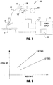
- the welding system 100 comprises a welding power supply 110 having a processor based controller 115 and a user interface/display 111.
- the power supply can be any type of known welding power supply, and embodiments of the invention are not limited thereto.
- the power supply 100 can be a PowerWave, as manufactured by The Lincoln Electric Company of Cleveland, Ohio, although embodiments are not limited thereto. Because of the manufacture, construction and operation of such power supplies, with powerful and sophisticated controllers are known, they need not be described in detail herein.
- the controller 115 can be any known processor based controller cable of controlling the operation of the welding system, and can have a CPU, memory, etc.
- the display 111 can be any known type of display that displays operational data related to a welding operation, user input data and the like. The display can also be a touch screen type allowing user input data to be input via the screen 111.
- the system 100 can also comprise a consumable source 125 from which a consumable 127 is supplied to a welding operation via a wire feeder 120, the operation of which is known.
- the wire feeder 120 can also have a controller 145 which can be coupled to the controller 115 of the power supply 110. In such embodiments data, information and controlcom-mands/instructions can be exchanged between the respective controllers.
- the wire feeder 120 can also have a user interface 147 to allow a user to input control information and weld process data into the wire feeder 120. Because of a communication coupling between the respective controllers (which can be via any known means, such as wired, wire or over the power cables) a user can control the welding operation via either the wire feeder 120 or the power supply 110.
- the wire 127 is delivered to a welding torch 130 of any known type for the welding of a workpiece or the weld metal W.
- the wire feeder 120 has a wire drive mechanism 143 which is capable of advancing and retracting the consumable 127 as described herein.
- Such systems can use motors, servos, rollers, etc. that grip the wire 127 and drive the wire in either an advancing or retracting direction. Because welding operations are widely known, they will not be described in detail herein.
- the welding torch 130 can have a wire drive mechanism 150 which is capable of assisting in the advancement and retraction of the wire.
- a wire drive mechanism 150 which is capable of assisting in the advancement and retraction of the wire.
- the torch can use the wire drive mechanism 150, or other similar suitable mechanism in the torch 130, to provide feedback regarding the wire feed speed of the welding operation.
- other known systems can be used to provide wire feed speed feedback, such as systems within the wire feeder, so long as the feedback systems are capable of accurately monitoring the wire feed speed of the consumable 127.
- the wire feed speed feedback system (e.g., 150) provides the detected wire feed speed to the wire feeder 120 controller 145, which can then determine an average wire feed speed over an desired duration of time.
- a shorting frequency can change during welding the wire feed speed of the welding operation will be changed.
- the CTWD can change (e.g., in manual or semi-automatic welding operations), and these changes will result in changes in the shorting frequency, and thus average wire feed speed.
- the shorting frequency decreases the average wire feed speed can increase because there will be less wire retraction events, and vice versa.
- Figure 2 depicts elative relationships between the desired or preset wire feed speed and average wire feed speed for a CTWD for 12.7 mm (0.5 inches) and 19.05 mm (0.75 inches) respectively.
- the slope defining the relationship between the desired wire feed speed and average wire feed speed changes. This can be a result of a different shorting frequency for a give welding operation, which is a result of a different CTWD.
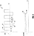
- the waveform 300 has a plurality of positive pulses 310 and negative pulses 320, where the positive pulses represent wire advancement and the negative pulses represent wire retraction.
- Each positive pulse 310 has a peak WFS 311 and a duration 313, and the negative pulses 320 have a peak retraction speed 321 and a duration 323.
- the duration of the respective pulses are not necessarily fixed but can be dictated by the shorting frequency, short duration, etc. of the welding process.
- each of the peak WFS values can be predetermined prior to the welding operation, and can be set by a user or can be determined by one of the respective controllers based on user input data regarding the welding operation.
- FIG. 3 Also shown in Figure 3 is a graphical representation of a desired average WFS 330, shown as a dashed line, as compared to the actual/detected WFS 340.
- the average WFS 330 represents an average over a period of time, which can be predetermined in either or both of the controllers, and the detected average WFS 340 represents the actual average WFS for the welding operation.
- the actual average 340 is less than the desired average 330. This can be a result of the CTWD being smaller than desired, which can result in an increase in the shorting frequency of the welding operation. This increase in shorting frequency will result in the wire spending more time in a retract state, than advancing, thus resulting in an actual average WFS which is less than desired.
- the resultant weld will likely have a deposition rate less than desired as less consumable is being added to the weld. Embodiments of the present invention address this, as discussed further below.
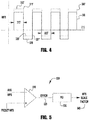
- Figure 4 depicts an exemplary waveform of the present invention.
- the waveform 300 from Figure 3 is shown for context.
- the system described herein adjusts the WFS waveform to achieve the desired average WFS. This can be done by increasing/decreasing the advancement and retraction peaks of the WFS pulses. For example, to increase the detected average WFS the system can cause the waveform to have higher positive peaks 311' and smaller negative peaks 321'. This results in an increase in the average WFS of the welding operation. To lower detected average WFS the positive peaks can be reduced and the negative peaks can be increased.
- embodiments of the present invention can achieve improved WFS control during a wire manipulation welding process, independent of the control of current and/or voltage in a welding operation.
- the welding arc current and voltage control are regulated separately from the wire feed speed. That is, in such system the power supply and wire feeder have voltage and current feedback and control circuits and systems that are capable of maintaining a desired current and voltage. Such systems are known and need not be described in detail herein. According to the present invention, the arc voltage and current feedback and control is entirely separate from the wire feed speed control as described herein. This is not to say that neither of the voltage and current are regulated, but the wire feed speed is not directly regulated based on arc voltage and/or current feedback, and the arc voltage and/or current is not directly controlled based on a detected wire feed speed. Such systems improve the operational efficiency of the system and allow the systems described herein to regulate wire feed speed in a desired fashion to provide consistent deposition of the consumable in the welding operation.
- the peaks of each of the negative and positive pulses were adjusted to achieve the desired average WFS.
- the need for adjustment is small only one of the respective peaks (i.e., positive or negative) can be adjusted. That is, in some exemplary embodiments if the actual average WFS is within a certain threshold or window relative to the desired average WFS only one of the positive or negative peaks is adjusted, and if the needed adjustment exceeds the threshold then each of the positive/negative peas are adjusted.
- this threshold value can be in the range of 2 to 20% of the desired or preset average WFS. In other exemplary embodiments, this threshold can be in the range of 5 to 12%.
- the controller of either the wire feeder 120 or the power supply 110 can determine which of the pulses is to be modified based on the type of welding operation being performed, along with other welding operation parameters. That is, for a given set of weld operation parameters it may be most desirable to adjust the average WFS via only the positive pulses of the WFS waveform, whereas in another given set of weld parameters it may be desirable to adjust only the negative peaks to achieve the desired WFS.
- weld process factors can include: welding process type, waveform type (e.g., STT, pulse, etc.), travel speed, consumable type (which can include construction, diameter, etc.), heat input, deposition rate, etc.
- embodiments can use any one, combination, or all of these parameters, as well as others not listed here, to determine the mechanics of the WFS modification to achieve the desired weld performance and weld goals.
- a controller can utilize a look-up table or state table, or the like and based on the input parameters determine which WFS modification techniques can be implemented.
- a user can input the various needed weld process parameters, and the controller (either wire feeder or power supply) can determine the WFS control protocols that will be used for the process, including any needed threshold values. This is explained further below.
- the controller can determine that the positive pulses should be adjusted first up to a threshold value, and if the differential in preset and actual WFS exceeds that threshold value then the negative pulses should also be adjusted.
- that threshold value may be different based on the welding parameters.
- the controller determines that positive pulses should be adjusted when the detected average WFS is within 10% of the desired average WFS, but for a second set of parameters the controller also determines that positive pulses should be adjusted but the threshold value is 15%, beyond which the negative pulses should also be adjusted.
- these determinations can be based on prepopulated look up tables, state tables or the like.
- the peaks of the pulses are modified, but in other embodiments the durations of the positive and/or negative pulses can be modified.
- the durations are dictated by the short circuit clearing of the welding waveform, and as such may vary but would vary based only on the duration of the short circuit events.
- the durations can be adjusted or be fixed in duration to achieve a desired average WFS. That is in some embodiments, the durations can be shortened or extended relative to the clearing of the short to adjust the average wire feed speed, while in other embodiments the durations can be fixed to set duration regardless of the duration of the short clearing.
- the controller can use various user inputs to determine whether or not WFS pulse duration can be utilized to adjust or control the wire feed speed.
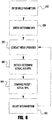
- Figure 5 depicts an exemplary WFS control circuit, that can be utilized in the controller of either the wire feeder or the power supply.
- the system controller can also be located remotely from the system 100 without departing from the scope and spirit of the present invention, such as in a separate system controller, etc.
- the control circuit 500 includes a comparator 510 which receives as input the detected average wire feed speed and the preset or desired average wire feed speed. The comparator compares each of the signals and outputs an error signal 520. The error signal 520 is provided to a proportional-integral-derivative controller (PID) 530 which then outputs a WFS scale factor 540.
- PID proportional-integral-derivative controller
- the scale factor 540 is then used by the controller to adjust the WFS waveform as described herein to achieve the desired output.
- the controller can adjust the detected average wire feed speed by (1 + WFS scale factor) to achieve the desired output.
- a PID can be used because the average WFS of a given welding operation is an integral of the total amount of wire provided to the weld over a period of time.
- the circuit 500 shown in Figure 5 is exemplary and not intended to be limiting. Other feedback and control circuits can be used without departing from the spirit or scope of the present invention.
- the control of the WFS is independent of the control of the welding arc current and/or voltage, and a constant delivery of consumable can be maintained for a given welding operation.
- the oscillation of the welding wire can occur at frequency in the range of 50 to 200 Hz, and in other embodiments is in the range of 75 to 150 Hz.
- the filtering window for the average wire feed speed detection and determination is in the range of 5 to 25 Hz, and in other embodiments can be in the range of 10 to 20Hz. Such filtering aids in ensuring that the determined average wire feed speed is not adversely influenced by noise, such as mechanical noise, which would interfere or adversely affect the data.
- FIG. 6 is a representative flow chart explaining an operation of exemplary embodiments of the present invention.
- this flow chart is exemplary and not intended to be limiting and the order of the items shown below can be altered without departing from the spirit or scope of the operation.
- at least some weld parameters are entered into the controller and/or system for the welding operation, followed by entry of the desired average WFS.
- all of this information can be input at the same time/in the same step.
- the desired average WFS can be determined by the controller based on at least some of the data input in step 610 (e.g., welding process type, waveform type (e.g., STT, pulse, etc.), travel speed, consumable type (which can include construction, diameter, etc.), heat input, deposition rate, etc.).
- the controller may have a predetermined desired WFS which would then be used for the welding operation.
- predetermined or prestored welding operations can be stored within the controller, or another memory, or uploaded to the controller having all of the desired information.
- the input welding parameters can include any of the parameters discussed herein, or any other weld parameters typically used for a given welding operation.
- a desired deposition rate can be input, along with information regarding the consumable, such as diameter, and he controller uses this information to determine a desired WFS rate.
- the welding operation can be commenced (630).
- the system detects/determines the actual average WFS and/or deposition rate of the welding operation (640). This determination can be made as described herein, using any known feedback system.
- the detected information is then compared to the desired or preset information (WFS or deposition rate, or both) (650). Based on the comparison 650 the controller can then adjust the wire feed speed or deposition rate as described herein to achieve the desired result. For example this can be done by adjusting the wire feed mechanisms in either, or both, of, the wire feeder or the torch (if so equipped). This control methodology is then maintained during the welding operation to achieve a constant deposition rate, which is not achievable with known wire manipulation systems.
- the controller/processor that receives and analyzes the provided information is within the power supply and/or the wire feeder. However, in other exemplary embodiments this can be done via a separate computer device, including a handheld device like a laptop, tablet, etc.
- the controller need not be in the power supply or wire feeder, but can be.
- REFERENCE NUMBERS 100 welding system 321 speed 110 power supply 321' peak 111 interface/ display 323 duration 115 controller 330 WFS 120 wire feeder 340 WFS 125 source 500 circuit 127 consumable 510 comparator 130 welding torch 520 signal 143 wire device mechanism 530 PID / controller 145 controller 540 factor 147 user interface 610 step 150 wire feed feedback system 630 operation 300 waveform 640 operation 310 pulse 650 operation 311 peak WFS (wire feed speed) W material 311' peak 313 duration 320 pulse
Landscapes
- Engineering & Computer Science (AREA)
- Physics & Mathematics (AREA)
- Plasma & Fusion (AREA)
- Mechanical Engineering (AREA)
- Theoretical Computer Science (AREA)
- Arc Welding Control (AREA)
Applications Claiming Priority (1)
| Application Number | Priority Date | Filing Date | Title |
|---|---|---|---|
| US15/481,251 US10500671B2 (en) | 2017-04-06 | 2017-04-06 | System and method for arc welding and wire manipulation control |
Publications (2)
| Publication Number | Publication Date |
|---|---|
| EP3385023A1 EP3385023A1 (en) | 2018-10-10 |
| EP3385023B1 true EP3385023B1 (en) | 2020-12-02 |
Family
ID=61911494
Family Applications (1)
| Application Number | Title | Priority Date | Filing Date |
|---|---|---|---|
| EP18166097.8A Active EP3385023B1 (en) | 2017-04-06 | 2018-04-06 | Systems for and method of arc welding with wire manipulation control |
Country Status (5)
| Country | Link |
|---|---|
| US (1) | US10500671B2 (ko) |
| EP (1) | EP3385023B1 (ko) |
| JP (1) | JP2018176280A (ko) |
| KR (1) | KR20180113459A (ko) |
| CN (1) | CN108687430A (ko) |
Families Citing this family (5)
| Publication number | Priority date | Publication date | Assignee | Title |
|---|---|---|---|---|
| EP3722038A1 (de) * | 2019-04-10 | 2020-10-14 | Fronius International GmbH | Mehrfach-impulsschweissverfahren |
| EP3903983A1 (de) * | 2020-04-29 | 2021-11-03 | FRONIUS INTERNATIONAL GmbH | Schweissverfahren und schweissvorrichtung zur durchführung eines schweissverfahrens |
| CN111805086B (zh) * | 2020-07-31 | 2021-12-14 | 国网上海市电力公司 | 一种基于调频相控式脉冲激光的脉动填丝焊接方法及系统 |
| CN112809145B (zh) * | 2021-02-02 | 2022-12-27 | 范瑞芬 | 一种焊丝送进性评价方法及装置 |
| CN115255571A (zh) * | 2022-07-27 | 2022-11-01 | 深圳市爱达思技术有限公司 | 焊丝伸出长度控制方法、装置、设备及存储介质 |
Family Cites Families (69)
| Publication number | Priority date | Publication date | Assignee | Title |
|---|---|---|---|---|
| US1840735A (en) | 1930-11-15 | 1932-01-12 | Lincoln Electric Co | Welding mechanism |
| US2073603A (en) | 1935-12-24 | 1937-03-16 | Walter D Krehbiel | Electric welding machine |
| US2163863A (en) | 1937-09-15 | 1939-06-27 | Gen Motors Corp | Apparatus for welding |
| US2498905A (en) | 1948-06-07 | 1950-02-28 | Utility Appliance Corp | Welding apparatus |
| US2628302A (en) | 1951-03-22 | 1953-02-10 | Air Reduction | Arc welding appararatus |
| GB759122A (en) | 1953-12-14 | 1956-10-10 | Union Carbide & Carbon Corp | Improvements in or relating to inert gas shielded arc welding |
| US2731536A (en) | 1953-12-14 | 1956-01-17 | Union Carbide & Carbon Corp | Welding wire positioning |
| US3068351A (en) | 1959-03-27 | 1962-12-11 | American Mach & Foundry | Welding machine |
| US3141085A (en) | 1962-11-23 | 1964-07-14 | Union Carbide Corp | Work-in-circuit consumable electrode arc welding |
| US3277269A (en) | 1964-02-10 | 1966-10-04 | Weltronic Co | Method and apparatus for arc welding |
| US3546415A (en) | 1968-11-07 | 1970-12-08 | Flame Spray Ind Inc | Electric arc metallizing device |
| US3777110A (en) | 1972-11-29 | 1973-12-04 | Ecodyne Corp | Welding gun |
| US4283617A (en) | 1976-02-03 | 1981-08-11 | Merrick Welding International, Inc. | Automatic pipe welding system |
| JPS5719177A (en) * | 1980-07-08 | 1982-02-01 | Mitsubishi Electric Corp | Pulse arc welding device |
| JPS58167078A (ja) | 1982-03-29 | 1983-10-03 | Mitsubishi Electric Corp | 溶接方法 |
| DE3609877A1 (de) | 1986-03-22 | 1987-09-24 | Blohm Voss Ag | Verfahren zum verhindern des festbrennens eines schweissdrahtes |
| BG49537A1 (en) * | 1988-04-22 | 1991-12-16 | Inst Tekhn Kib I Robotika Pri | Method and device for pulsation feeding of continuous electrode wire |
| CN1012565B (zh) * | 1988-06-08 | 1991-05-08 | 化工部化机院氟塑料应用技术研究所 | 一种聚四氟乙烯防腐制品及其制造方法 |
| US4935598A (en) | 1988-11-14 | 1990-06-19 | Abb Power T&D Company Inc. | Automatic arc welding with filler wire |
| KR100219813B1 (ko) * | 1990-04-17 | 1999-09-01 | 니시마쓰 다이조 | Mag 아아크 용접 방법 및 용접장치 |
| US5191185A (en) | 1990-10-30 | 1993-03-02 | Westinghouse Electric Corp. | Girth and seal welding apparatus |
| US5332342A (en) | 1991-04-26 | 1994-07-26 | Honda Giken Kogyo Kabushiki Kaisha | Electrode tip dresser and cutter for electrode tip dresser |
| JP2536334B2 (ja) | 1991-07-24 | 1996-09-18 | 日本鋼管株式会社 | パイプの円周溶接方法 |
| US5275336A (en) | 1991-12-04 | 1994-01-04 | The Perkin-Elmer Corporation | Wire thermal spray gun and method |
| JP2751744B2 (ja) * | 1992-07-07 | 1998-05-18 | 日本鋼管株式会社 | 複数電極高速回転アークの溶接電流制御方法 |
| US5916464A (en) | 1997-08-26 | 1999-06-29 | Geiger; Michael B. | Welding force feedback wire feed system |
| CA2312307A1 (en) | 1997-09-04 | 1999-03-11 | International Metalizing Corporation | Twin wire electric arc metalizing device |
| DE69940415D1 (de) * | 1998-09-04 | 2009-04-02 | Daihen Corp | Lichtbogenschweissverfahren |
| JP2000202629A (ja) | 1999-01-19 | 2000-07-25 | Toyota Motor Corp | 半自動溶接法及びそれに用いる半自動溶接機 |
| US6160241A (en) | 1999-03-16 | 2000-12-12 | Lincoln Global, Inc. | Method and apparatus for electric arc welding |
| US7116071B2 (en) | 2000-12-06 | 2006-10-03 | Milwaukee Electric Tool Corporation | Power tool and motor controller |
| US6984806B2 (en) | 2002-07-23 | 2006-01-10 | Illinois Tool Works Inc. | Method and apparatus for retracting and advancing a welding wire |
| US6963048B2 (en) | 2002-07-23 | 2005-11-08 | Illinois Tool Works Inc. | Method and apparatus for welding with mechanical arc control |
| US6969823B2 (en) | 2002-07-23 | 2005-11-29 | Illinois Tool Works Inc. | Method and apparatus for controlling a welding system |
| US7102099B2 (en) | 2002-07-23 | 2006-09-05 | Illinois Tool Works Inc. | Method and apparatus for feeding wire to a welding arc |
| US6720529B2 (en) | 2002-09-05 | 2004-04-13 | Illinois Tool Works Inc. | Autothread control for a wire feeder of a welding system |
| US6909067B2 (en) | 2002-10-09 | 2005-06-21 | Illinois Tool Works Inc. | Method and apparatus for welding with CV control |
| US6930279B2 (en) * | 2003-07-25 | 2005-08-16 | Lincoln Global, Inc. | Electric arc welder and method for controlling the welding process of the welder |
| US7339135B2 (en) * | 2004-06-04 | 2008-03-04 | Illinois Tool Works Inc. | Welding arc stabilization process |
| US7700893B2 (en) | 2004-12-22 | 2010-04-20 | Illinois Tool Works Inc. | System and method for calibrating wire feeder motor control |
| JP5001536B2 (ja) | 2005-07-19 | 2012-08-15 | 株式会社ダイヘン | アーク溶接トーチ |
| CN2871090Y (zh) | 2006-02-24 | 2007-02-21 | 广东省顺德开关厂有限公司 | 一种自动焊接装置 |
| JP4875392B2 (ja) | 2006-03-30 | 2012-02-15 | 株式会社ダイヘン | アーク溶接ロボット制御装置 |
| US8704131B2 (en) | 2006-03-31 | 2014-04-22 | Illinois Tool Works Inc. | Method and apparatus for pulse welding |
| US8592719B2 (en) | 2006-12-22 | 2013-11-26 | Illinois Tool Works Inc. | System and method for identifying welding consumable wear |
| JP5201266B2 (ja) * | 2009-07-29 | 2013-06-05 | パナソニック株式会社 | アーク溶接方法およびアーク溶接装置 |
| CN201559015U (zh) * | 2009-11-06 | 2010-08-25 | 北京工业大学 | 一种双电机配合焊丝协调机构的送丝系统 |
| EP2533936B1 (en) | 2010-02-10 | 2018-07-25 | Hobart Brothers LLC | Aluminum alloy welding wire |
| US9770788B2 (en) | 2010-02-10 | 2017-09-26 | Hobart Brothers Company | Aluminum alloy welding wire |
| US8395085B2 (en) * | 2010-02-23 | 2013-03-12 | Illinois Tool Works Inc. | Wire feed speed referenced variable frequency pulse welding system |
| US20110309063A1 (en) * | 2010-06-17 | 2011-12-22 | lllinois Tool Works Inc. | Welding wire feeder with magnetic rotational speed sensor |
| US9643276B2 (en) | 2010-06-17 | 2017-05-09 | Illinois Tool Works Inc. | Welding wire retraction system and method |
| US20120199566A1 (en) | 2010-12-14 | 2012-08-09 | Lincoln Global, Inc. | Welding apparatus with automated welding wire retraction |
| US9498839B2 (en) | 2010-12-14 | 2016-11-22 | Lincoln Global, Inc. | Welding apparatus with automated welding wire retraction |
| US9821400B2 (en) | 2010-12-14 | 2017-11-21 | Lincoln Global, Inc. | Manual welding apparatus having an automatic wire retract method |
| JP5408364B2 (ja) * | 2011-06-03 | 2014-02-05 | パナソニック株式会社 | アーク溶接制御方法およびアーク溶接装置 |
| US20130299476A1 (en) * | 2011-07-12 | 2013-11-14 | Panasonic Corporation | Arc welding control method and arc welding device |
| BR112014019148B1 (pt) | 2012-02-10 | 2019-01-02 | Lincoln Global Inc | método de retração de fio automática; método para aprimorar a segurança de uma operação de soldagem com o uso de um maçarico de soldagem que emprega um gatilho para avançar um arame de soldagem; método para uma operação de soldagem com o uso de um maçarico de soldagem que emprega um gatilho para avançar um arame de soldagem; e sistemas de soldagem |
| US9050676B2 (en) * | 2012-03-02 | 2015-06-09 | Lincoln Global, Inc. | Apparatus and method for starting arc welding process |
| KR102056043B1 (ko) * | 2012-06-18 | 2019-12-16 | 파나소닉 아이피 매니지먼트 가부시키가이샤 | 아크 용접 방법 및 아크 용접 장치 |
| US9132500B2 (en) * | 2012-07-10 | 2015-09-15 | Illinois Tool Works Inc. | Methods and systems for feeding filler material to a welding operation |
| US9676051B2 (en) * | 2012-10-18 | 2017-06-13 | Lincoln Global, Inc. | System and methods providing modulation schemes for achieving a weld bead appearance |
| US10040143B2 (en) | 2012-12-12 | 2018-08-07 | Illinois Tool Works Inc. | Dabbing pulsed welding system and method |
| US10835983B2 (en) | 2013-03-14 | 2020-11-17 | Illinois Tool Works Inc. | Electrode negative pulse welding system and method |
| CN103203530B (zh) * | 2013-04-25 | 2016-08-17 | 广州友田机电设备有限公司 | 一种脉冲mig焊接电弧控制方法 |
| JP6166627B2 (ja) | 2013-09-17 | 2017-07-19 | 株式会社ダイヘン | ワイヤ送給システム、及びワイヤ速度制御装置 |
| WO2015107974A1 (ja) * | 2014-01-15 | 2015-07-23 | 株式会社ダイヘン | アーク溶接制御方法 |
| CN103920970B (zh) * | 2014-04-03 | 2016-05-25 | 北京星航机电装备有限公司 | 一种焊丝调速控制系统 |
| JP6425496B2 (ja) * | 2014-10-30 | 2018-11-21 | 株式会社ダイヘン | アーク溶接の状態監視方法 |
-
2017
- 2017-04-06 US US15/481,251 patent/US10500671B2/en active Active
-
2018
- 2018-04-03 KR KR1020180038509A patent/KR20180113459A/ko not_active Application Discontinuation
- 2018-04-03 CN CN201810290244.6A patent/CN108687430A/zh active Pending
- 2018-04-05 JP JP2018073033A patent/JP2018176280A/ja active Pending
- 2018-04-06 EP EP18166097.8A patent/EP3385023B1/en active Active
Non-Patent Citations (1)
| Title |
|---|
| None * |
Also Published As
| Publication number | Publication date |
|---|---|
| EP3385023A1 (en) | 2018-10-10 |
| US20180290228A1 (en) | 2018-10-11 |
| JP2018176280A (ja) | 2018-11-15 |
| CN108687430A (zh) | 2018-10-23 |
| KR20180113459A (ko) | 2018-10-16 |
| US10500671B2 (en) | 2019-12-10 |
Similar Documents
| Publication | Publication Date | Title |
|---|---|---|
| EP3385023B1 (en) | Systems for and method of arc welding with wire manipulation control | |
| EP1407849B1 (en) | Method and apparatus for welding with constant voltage control | |
| US10189107B2 (en) | Short arc welding system | |
| US20140124492A1 (en) | Method and system to control heat input in a welding operation | |
| US11117210B2 (en) | Calculating output inductance of a weld secondary | |
| US10195681B2 (en) | Short arc welding system | |
| JP2018176280A5 (ko) | ||
| US7091449B2 (en) | Voltage regulated MIG welding using a constant current power source | |
| KR20200116058A (ko) | 아크 용접 회로의 실시간 저항 모니터링 | |
| CN102189314B (zh) | 非熔化电极电弧焊接控制方法 | |
| JP2014237155A (ja) | アーク溶接装置、アーク溶接システム及びアーク溶接方法 | |
| CN111511495B (zh) | 焊接型系统的自动工艺和/或设置 | |
| US20220274196A1 (en) | Method and Device for Stabilizing a Transition between Various Welding-Process Phases of a Welding Process | |
| WO2015124996A2 (en) | Method and system to use combination filler wire feed and high intensity energy source for welding | |
| KR20190077336A (ko) | 아크 용접 제어 방법 | |
| WO2022044700A1 (ja) | アーク溶接の制御方法、溶接電源、溶接システム及び検出方法 | |
| EP4144470A1 (en) | System to provide interfaces for control of welding-type systems | |
| JP6274173B2 (ja) | アーク溶接システムおよびアーク溶接方法 | |
| KR102259226B1 (ko) | 아크 용접 방법 | |
| JP2020138207A (ja) | パルスアーク溶接の出力制御方法 |
Legal Events
| Date | Code | Title | Description |
|---|---|---|---|
| PUAI | Public reference made under article 153(3) epc to a published international application that has entered the european phase |
Free format text: ORIGINAL CODE: 0009012 |
|
| STAA | Information on the status of an ep patent application or granted ep patent |
Free format text: STATUS: THE APPLICATION HAS BEEN PUBLISHED |
|
| AK | Designated contracting states |
Kind code of ref document: A1 Designated state(s): AL AT BE BG CH CY CZ DE DK EE ES FI FR GB GR HR HU IE IS IT LI LT LU LV MC MK MT NL NO PL PT RO RS SE SI SK SM TR |
|
| AX | Request for extension of the european patent |
Extension state: BA ME |
|
| STAA | Information on the status of an ep patent application or granted ep patent |
Free format text: STATUS: REQUEST FOR EXAMINATION WAS MADE |
|
| 17P | Request for examination filed |
Effective date: 20190404 |
|
| RBV | Designated contracting states (corrected) |
Designated state(s): AL AT BE BG CH CY CZ DE DK EE ES FI FR GB GR HR HU IE IS IT LI LT LU LV MC MK MT NL NO PL PT RO RS SE SI SK SM TR |
|
| STAA | Information on the status of an ep patent application or granted ep patent |
Free format text: STATUS: EXAMINATION IS IN PROGRESS |
|
| 17Q | First examination report despatched |
Effective date: 20190906 |
|
| GRAP | Despatch of communication of intention to grant a patent |
Free format text: ORIGINAL CODE: EPIDOSNIGR1 |
|
| STAA | Information on the status of an ep patent application or granted ep patent |
Free format text: STATUS: GRANT OF PATENT IS INTENDED |
|
| INTG | Intention to grant announced |
Effective date: 20200805 |
|
| GRAS | Grant fee paid |
Free format text: ORIGINAL CODE: EPIDOSNIGR3 |
|
| GRAA | (expected) grant |
Free format text: ORIGINAL CODE: 0009210 |
|
| STAA | Information on the status of an ep patent application or granted ep patent |
Free format text: STATUS: THE PATENT HAS BEEN GRANTED |
|
| AK | Designated contracting states |
Kind code of ref document: B1 Designated state(s): AL AT BE BG CH CY CZ DE DK EE ES FI FR GB GR HR HU IE IS IT LI LT LU LV MC MK MT NL NO PL PT RO RS SE SI SK SM TR |
|
| REG | Reference to a national code |
Ref country code: GB Ref legal event code: FG4D |
|
| REG | Reference to a national code |
Ref country code: AT Ref legal event code: REF Ref document number: 1340360 Country of ref document: AT Kind code of ref document: T Effective date: 20201215 Ref country code: CH Ref legal event code: EP |
|
| REG | Reference to a national code |
Ref country code: IE Ref legal event code: FG4D |
|
| REG | Reference to a national code |
Ref country code: DE Ref legal event code: R096 Ref document number: 602018010246 Country of ref document: DE |
|
| REG | Reference to a national code |
Ref country code: FI Ref legal event code: FGE |
|
| REG | Reference to a national code |
Ref country code: SE Ref legal event code: TRGR |
|
| PG25 | Lapsed in a contracting state [announced via postgrant information from national office to epo] |
Ref country code: RS Free format text: LAPSE BECAUSE OF FAILURE TO SUBMIT A TRANSLATION OF THE DESCRIPTION OR TO PAY THE FEE WITHIN THE PRESCRIBED TIME-LIMIT Effective date: 20201202 Ref country code: NO Free format text: LAPSE BECAUSE OF FAILURE TO SUBMIT A TRANSLATION OF THE DESCRIPTION OR TO PAY THE FEE WITHIN THE PRESCRIBED TIME-LIMIT Effective date: 20210302 Ref country code: GR Free format text: LAPSE BECAUSE OF FAILURE TO SUBMIT A TRANSLATION OF THE DESCRIPTION OR TO PAY THE FEE WITHIN THE PRESCRIBED TIME-LIMIT Effective date: 20210303 |
|
| REG | Reference to a national code |
Ref country code: NL Ref legal event code: MP Effective date: 20201202 |
|
| PG25 | Lapsed in a contracting state [announced via postgrant information from national office to epo] |
Ref country code: BG Free format text: LAPSE BECAUSE OF FAILURE TO SUBMIT A TRANSLATION OF THE DESCRIPTION OR TO PAY THE FEE WITHIN THE PRESCRIBED TIME-LIMIT Effective date: 20210302 Ref country code: LV Free format text: LAPSE BECAUSE OF FAILURE TO SUBMIT A TRANSLATION OF THE DESCRIPTION OR TO PAY THE FEE WITHIN THE PRESCRIBED TIME-LIMIT Effective date: 20201202 |
|
| PG25 | Lapsed in a contracting state [announced via postgrant information from national office to epo] |
Ref country code: HR Free format text: LAPSE BECAUSE OF FAILURE TO SUBMIT A TRANSLATION OF THE DESCRIPTION OR TO PAY THE FEE WITHIN THE PRESCRIBED TIME-LIMIT Effective date: 20201202 Ref country code: NL Free format text: LAPSE BECAUSE OF FAILURE TO SUBMIT A TRANSLATION OF THE DESCRIPTION OR TO PAY THE FEE WITHIN THE PRESCRIBED TIME-LIMIT Effective date: 20201202 |
|
| REG | Reference to a national code |
Ref country code: LT Ref legal event code: MG9D |
|
| PG25 | Lapsed in a contracting state [announced via postgrant information from national office to epo] |
Ref country code: LT Free format text: LAPSE BECAUSE OF FAILURE TO SUBMIT A TRANSLATION OF THE DESCRIPTION OR TO PAY THE FEE WITHIN THE PRESCRIBED TIME-LIMIT Effective date: 20201202 Ref country code: RO Free format text: LAPSE BECAUSE OF FAILURE TO SUBMIT A TRANSLATION OF THE DESCRIPTION OR TO PAY THE FEE WITHIN THE PRESCRIBED TIME-LIMIT Effective date: 20201202 Ref country code: SK Free format text: LAPSE BECAUSE OF FAILURE TO SUBMIT A TRANSLATION OF THE DESCRIPTION OR TO PAY THE FEE WITHIN THE PRESCRIBED TIME-LIMIT Effective date: 20201202 Ref country code: PT Free format text: LAPSE BECAUSE OF FAILURE TO SUBMIT A TRANSLATION OF THE DESCRIPTION OR TO PAY THE FEE WITHIN THE PRESCRIBED TIME-LIMIT Effective date: 20210405 Ref country code: CZ Free format text: LAPSE BECAUSE OF FAILURE TO SUBMIT A TRANSLATION OF THE DESCRIPTION OR TO PAY THE FEE WITHIN THE PRESCRIBED TIME-LIMIT Effective date: 20201202 Ref country code: EE Free format text: LAPSE BECAUSE OF FAILURE TO SUBMIT A TRANSLATION OF THE DESCRIPTION OR TO PAY THE FEE WITHIN THE PRESCRIBED TIME-LIMIT Effective date: 20201202 Ref country code: SM Free format text: LAPSE BECAUSE OF FAILURE TO SUBMIT A TRANSLATION OF THE DESCRIPTION OR TO PAY THE FEE WITHIN THE PRESCRIBED TIME-LIMIT Effective date: 20201202 |
|
| REG | Reference to a national code |
Ref country code: DE Ref legal event code: R097 Ref document number: 602018010246 Country of ref document: DE |
|
| PG25 | Lapsed in a contracting state [announced via postgrant information from national office to epo] |
Ref country code: IS Free format text: LAPSE BECAUSE OF FAILURE TO SUBMIT A TRANSLATION OF THE DESCRIPTION OR TO PAY THE FEE WITHIN THE PRESCRIBED TIME-LIMIT Effective date: 20210402 |
|
| PLBE | No opposition filed within time limit |
Free format text: ORIGINAL CODE: 0009261 |
|
| STAA | Information on the status of an ep patent application or granted ep patent |
Free format text: STATUS: NO OPPOSITION FILED WITHIN TIME LIMIT |
|
| PG25 | Lapsed in a contracting state [announced via postgrant information from national office to epo] |
Ref country code: AL Free format text: LAPSE BECAUSE OF FAILURE TO SUBMIT A TRANSLATION OF THE DESCRIPTION OR TO PAY THE FEE WITHIN THE PRESCRIBED TIME-LIMIT Effective date: 20201202 |
|
| 26N | No opposition filed |
Effective date: 20210903 |
|
| PG25 | Lapsed in a contracting state [announced via postgrant information from national office to epo] |
Ref country code: DK Free format text: LAPSE BECAUSE OF FAILURE TO SUBMIT A TRANSLATION OF THE DESCRIPTION OR TO PAY THE FEE WITHIN THE PRESCRIBED TIME-LIMIT Effective date: 20201202 Ref country code: SI Free format text: LAPSE BECAUSE OF FAILURE TO SUBMIT A TRANSLATION OF THE DESCRIPTION OR TO PAY THE FEE WITHIN THE PRESCRIBED TIME-LIMIT Effective date: 20201202 Ref country code: MC Free format text: LAPSE BECAUSE OF FAILURE TO SUBMIT A TRANSLATION OF THE DESCRIPTION OR TO PAY THE FEE WITHIN THE PRESCRIBED TIME-LIMIT Effective date: 20201202 |
|
| PG25 | Lapsed in a contracting state [announced via postgrant information from national office to epo] |
Ref country code: LU Free format text: LAPSE BECAUSE OF NON-PAYMENT OF DUE FEES Effective date: 20210406 |
|
| REG | Reference to a national code |
Ref country code: BE Ref legal event code: MM Effective date: 20210430 |
|
| PG25 | Lapsed in a contracting state [announced via postgrant information from national office to epo] |
Ref country code: FR Free format text: LAPSE BECAUSE OF NON-PAYMENT OF DUE FEES Effective date: 20210430 Ref country code: ES Free format text: LAPSE BECAUSE OF FAILURE TO SUBMIT A TRANSLATION OF THE DESCRIPTION OR TO PAY THE FEE WITHIN THE PRESCRIBED TIME-LIMIT Effective date: 20201202 Ref country code: LI Free format text: LAPSE BECAUSE OF NON-PAYMENT OF DUE FEES Effective date: 20210430 Ref country code: CH Free format text: LAPSE BECAUSE OF NON-PAYMENT OF DUE FEES Effective date: 20210430 |
|
| PG25 | Lapsed in a contracting state [announced via postgrant information from national office to epo] |
Ref country code: IE Free format text: LAPSE BECAUSE OF NON-PAYMENT OF DUE FEES Effective date: 20210406 |
|
| PG25 | Lapsed in a contracting state [announced via postgrant information from national office to epo] |
Ref country code: IS Free format text: LAPSE BECAUSE OF FAILURE TO SUBMIT A TRANSLATION OF THE DESCRIPTION OR TO PAY THE FEE WITHIN THE PRESCRIBED TIME-LIMIT Effective date: 20210402 |
|
| PG25 | Lapsed in a contracting state [announced via postgrant information from national office to epo] |
Ref country code: BE Free format text: LAPSE BECAUSE OF NON-PAYMENT OF DUE FEES Effective date: 20210430 |
|
| REG | Reference to a national code |
Ref country code: AT Ref legal event code: UEP Ref document number: 1340360 Country of ref document: AT Kind code of ref document: T Effective date: 20201202 |
|
| GBPC | Gb: european patent ceased through non-payment of renewal fee |
Effective date: 20220406 |
|
| PG25 | Lapsed in a contracting state [announced via postgrant information from national office to epo] |
Ref country code: GB Free format text: LAPSE BECAUSE OF NON-PAYMENT OF DUE FEES Effective date: 20220406 |
|
| PGFP | Annual fee paid to national office [announced via postgrant information from national office to epo] |
Ref country code: PL Payment date: 20230327 Year of fee payment: 6 |
|
| PG25 | Lapsed in a contracting state [announced via postgrant information from national office to epo] |
Ref country code: CY Free format text: LAPSE BECAUSE OF FAILURE TO SUBMIT A TRANSLATION OF THE DESCRIPTION OR TO PAY THE FEE WITHIN THE PRESCRIBED TIME-LIMIT Effective date: 20201202 |
|
| PG25 | Lapsed in a contracting state [announced via postgrant information from national office to epo] |
Ref country code: HU Free format text: LAPSE BECAUSE OF FAILURE TO SUBMIT A TRANSLATION OF THE DESCRIPTION OR TO PAY THE FEE WITHIN THE PRESCRIBED TIME-LIMIT; INVALID AB INITIO Effective date: 20180406 |
|
| PGFP | Annual fee paid to national office [announced via postgrant information from national office to epo] |
Ref country code: IT Payment date: 20230428 Year of fee payment: 6 Ref country code: DE Payment date: 20230418 Year of fee payment: 6 |
|
| PGFP | Annual fee paid to national office [announced via postgrant information from national office to epo] |
Ref country code: SE Payment date: 20230419 Year of fee payment: 6 Ref country code: FI Payment date: 20230417 Year of fee payment: 6 Ref country code: AT Payment date: 20230414 Year of fee payment: 6 |
|
| PG25 | Lapsed in a contracting state [announced via postgrant information from national office to epo] |
Ref country code: MK Free format text: LAPSE BECAUSE OF FAILURE TO SUBMIT A TRANSLATION OF THE DESCRIPTION OR TO PAY THE FEE WITHIN THE PRESCRIBED TIME-LIMIT Effective date: 20201202 |