EP3383751B1 - Système pour l'allimentation d'une pile d'etiquettes - Google Patents
Système pour l'allimentation d'une pile d'etiquettes Download PDFInfo
- Publication number
- EP3383751B1 EP3383751B1 EP16797518.4A EP16797518A EP3383751B1 EP 3383751 B1 EP3383751 B1 EP 3383751B1 EP 16797518 A EP16797518 A EP 16797518A EP 3383751 B1 EP3383751 B1 EP 3383751B1
- Authority
- EP
- European Patent Office
- Prior art keywords
- drive
- motor
- drive motor
- carriage
- torque
- Prior art date
- Legal status (The legal status is an assumption and is not a legal conclusion. Google has not performed a legal analysis and makes no representation as to the accuracy of the status listed.)
- Active
Links
Images


Classifications
-
- B—PERFORMING OPERATIONS; TRANSPORTING
- B65—CONVEYING; PACKING; STORING; HANDLING THIN OR FILAMENTARY MATERIAL
- B65C—LABELLING OR TAGGING MACHINES, APPARATUS, OR PROCESSES
- B65C9/00—Details of labelling machines or apparatus
- B65C9/08—Label feeding
- B65C9/10—Label magazines
Definitions
- the present invention relates to a system for feeding a stack of labels comprising a guide and a slide guided on the guide, which carries a biasing element for a stack of labels.
- the carriage is biased against a removal position on the guide, which leads to the label stack being positioned at the removal position in such a way that the foremost label of the label stack is moved by means of a driver device, e.g. a glue segment can be removed.
- the carriage can be moved along the guide by means of a drive mechanism.
- the drive mechanism is driven by a drive motor. This moves the carriage from a working position to a retracted release or fill position for the label stack.
- the label stack is pressed into the removal position by means of a spring device, which on the one hand has the advantage that when a label is removed, the entire label stack can move somewhat backwards. This is important because when a label is removed the driver device e.g. presses with the glue segment into the stack of labels and thus pushes it backwards from the removal position by a play clearance ⁇ s.
- the spring device can easily accommodate this game.
- a disadvantage of this device is, however, that the force acting on the label stack depends on the degree of filling, i.e. is of the thickness of the stack of labels and that on the other hand, the entire device is relatively complicated and expensive.
- a system according to the preamble of claim 1 is here US 4,978,416 known.
- the drive mechanism obtains the biasing force for the bias of the carriage in the removal position from the torque of the drive motor.
- the torque of the running driven drive motor that pushes the stack of labels into the removal position.
- the biasing element can be, for example, a slider if the stack of labels slides on a base, or a receiving element if the entire stack of labels is held by the biasing element.
- the removal position is preferably at one end of the guide, but can also be arranged somewhat beforehand.
- the slide is mounted on the guide, in particular via sliding elements or on rollers, in such a way that it can be moved back and forth on the guide with as little resistance as possible.
- the propulsion or the movement of the carriage is realized by the drive mechanism.
- the drive mechanism has a rotating flexible drive means which is driven by the drive motor and which is stretched between at least two deflection rollers.
- the carriage is connected to the drive means in particular via a driver.
- the drive means is preferably a drive belt, in particular an endless belt, which can either be smooth or toothed.
- the drive motor either drives the drive means directly, for example via a toothed roller or a friction roller, or drives one of the deflection rollers, which is currently the more common solution.
- the carriage is then connected at one point to the drive means via a driver and is moved along the guide via the drive means.
- the drive mechanism is designed as a spindle, more precisely as a threaded spindle, which, for example, simultaneously form the guide for the slide can.
- the spindle is rotated by the drive motor and a threaded nut-like threaded element that meshes with the spindle is provided on the slide. Rotation of the spindle thus moves the carriage on the spindle back and forth in accordance with the direction of rotation and speed of rotation of the spindle.
- the thread pitch and also the other parameters of the thread of the spindle and the threaded element are selected such that the thread is not self-locking.
- the drive mechanism has a continuous slip clutch which is used when the pretensioning element of the carriage bears against the label stack and the motor continues to rotate nonetheless.
- this permanent slip clutch which can be a friction clutch, for example, a certain torque is constantly transferred to the drive mechanism via the permanent slip clutch, and thus into a pressing force of the biasing element against the stack of labels.
- the permanent slip clutch is preferably a permanent slip clutch which operates according to the magnetic hysteresis principle, which has the advantage that the permanent slip clutch is maintenance-free and largely unaffected by external influences, for example temperature. The transmitted torque is therefore solely dependent on the rotational speed of the drive motor.
- the guide is preferably designed as a linear guide.
- the drive motor is an electric motor, in particular a permanent magnet motor. It is particularly advantageous to use a closed-loop motor as an electric motor which, at least in the pressing operation, ie when the pretensioning element presses against the stack of labels, is torque controlled.
- Such a closed-loop motor is safe from standstill and, when stationary, applies a defined torque in accordance with the control of the closed-loop motor, with which a defined pretensioning force can be exerted on the pretensioning element.
- the torque is set via the control signals for the closed-loop stepper motor.
- an elastic element e.g. a spiral spring, a rubber element or helical springs are provided which allow a movement play ⁇ S of the prestressing element in the direction of the guide facing away from the removal position.
- the slide or the pretensioning element can avoid this removal movement ⁇ S without the motor being deflected against its drive direction.
- the drive mechanism could be built without the elastic element.
- the elastic element is arranged between the driver of the slide and the biasing element, in which way the elastic element does not require a separate space in the drive mechanism, since the elastic element e.g. can be integrated into the sled.
- the threaded element can thus be suspended as a driver on the slide between two coil springs, which are supported on the slide.
- the biasing element is movable relative to the threaded element in both directions by a certain amount of play, which should in any case be as large as the above-mentioned required movement play ⁇ s.
- the invention relates to a method for prestressing a slide that can be moved on a guide by means of a drive motor for prestressing a stack of labels into the removal position.
- the force for the pretensioning of the slide into the removal position from the torque of the Drive axis of the drive motor generated or derived.
- this has the advantage that no separate spring device is required to pretension the pretensioning element against the stack of labels.
- This has the advantage that the force is always the same regardless of the thickness of the label stack and that the entire mechanism is considerably simplified.
- a closed-loop stepper motor is preferably used as the drive motor, which is stationary and therefore does not require a device, such as a continuous slip clutch, in order to transmit the torque to the biasing element when the biasing element lies essentially immovably against the stack of labels.
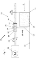
- Fig. 1 shows a feed system 10 for pretensioning a stack of labels 12 in a removal position 14.
- the stack of labels 12 slides on a smooth surface 16 (for example a metal feed surface) and is pushed into the removal position 14 by a slide 18 on its rear side facing away from the removal position 14.
- the slide forms the biasing element of the feed system according to the invention.
- the system also has a drive motor 20 and a drive mechanism 22, which has a spindle 24 rotated by the drive motor 20 and a carriage 26 guided on the spindle 24.
- the carriage 26 is movably guided as a driver on the spindle by means of a non-rotatable threaded element 28.
- the threaded element 28 is supported, for example, via two helical springs 30, 32 against two support walls 34, 36 of the slide 26.
- the slider 18 is fixed to the carriage 26. Due to the resilient mounting of the slide 26 on the threaded element 28, the slide 26 and thus the slide 18 can be moved somewhat in the direction of the guide, in both directions according to the double arrow shown around the threaded element 28. This plays a role, as will be explained below.
- a driver device for example a glue segment
- the glue segment presses against the label stack 12 with the force F, the entire label stack being pressed away from the removal position 14 in the direction of the slide 18 by the play clearance ⁇ s.
- This movement play ⁇ s is absorbed by the coil springs 30, 32, which hold the slide 26 resiliently on the threaded element 28.
- the biasing force VF of the slider 18 against the label stack 12 is derived from the torque of the drive motor 20 which is constantly driven during the removal of labels.
- this pretensioning force VF is generated by the torque which is generated by the current actuation of the drive motor 20 during the removal generated from labels from the label stack. This torque is converted via the threaded element 28 into the biasing force VF, which presses the slider 18 against the label stack 12 in the direction of the removal position 14.
- the distance ⁇ s through the slide can be carried out by the spindle through the Backward movement of the carriage by the distance ⁇ s is rotated backwards by a corresponding angle of rotation against the permanent torque of the motor. If the label was then removed from the label stack, the carriage is moved back to the starting position by the permanent torque of the motor.
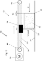
- the feed system 14 according to the invention Fig. 2 has one of Fig. 1 deviating drive mechanism 42, which consists of a flexible drive means 44, preferably in the form of an endless belt, which is stretched between two deflection rollers 46, 48. Between the two deflection rollers 46, 48, a linear guide 50 for the carriage 26 is also formed, which, as in FIG Fig. 1 can be built.
- the difference between the carriage 26 from the embodiment of FIG Fig. 2 and the carriage 26 from the embodiment of FIG Fig. 1 is that in this Embodiment of the Fig. 2 the driver is not a threaded element, but simply an element which is fastened to the endless belt 44, so that the two coil springs 30, 32 act on this element.
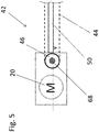
- Fig. 3 shows one too Fig. 2 largely analog system 60, which is based on system 40 Fig. 2 the only difference is that here the carriage 62 is connected to the endless belt 44 via a driver 64, the driver 64 being connected to the carriage 62 via an elastic element, for example a rubber element 66. In contrast to Fig. 2 So there are no coil springs, but an elastic rubber element for connecting the slide to the driver.
- Fig. 4 again shows a to Fig. 1 largely identical system 70 with a drive mechanism containing a spindle drive 24, 26, 28.
- the drive mechanism 72 identifies the components of the drive mechanism 22 Fig. 1
- Another slip clutch 74 which connects the spindle 24 to the shaft of the drive motor 20.
- the components of the drive mechanism 22 are preferably not designed to be self-locking in order to reverse the movement of the slider 18 in a reverse rotation of the spindle to be able to convert.
- a permanent slip clutch 74 could also be provided between the slide 18 and the threaded element 28 arranged on the spindle, as a result of which, when the slide is moved backwards, the threaded element 28 is rotated about its longitudinal axis relative to the slide 26, but the spindle is not rotated backwards.
- a continuous slip clutch 68 is provided, which can either be a friction clutch or a permanent slip clutch operating according to the magnetic hysteresis principle.
- the torque of the motor can be continuously transmitted to the drive mechanism, whereby the drive motor 20 can continue to rotate.
- the constant biasing force VF is transmitted to the label stack by means of the continuous slip clutch, the drive motor 22 not having to be stationary.
- This torque transmitted to the endless belt 44 is then converted via the driver of the carriage 26 into a biasing force VF of the slider 18 on the label stack 12.
Landscapes
- Sheets, Magazines, And Separation Thereof (AREA)
- Labeling Devices (AREA)
Claims (15)
- Système pour l'alimentation d'une pile d'étiquettes (12), comportant un élément de guidage (24 ; 50), un chariot (26 ; 62) guidé au niveau de l'élément de guidage, qui comprend au moins un élément de précontrainte (18) pour la pile d'étiquettes, lequel le chariot est précontraint au niveau de l'élément de guidage contre une position de prélèvement (14) de la pile d'étiquettes, dans lequel le chariot (26 ; 62) peut être déplacé au moyen d'un mécanisme d'entraînement (22 ; 42 ; 72) entraîné par un moteur d'entraînement (20) le long de l'élément de guidage, dans lequel le mécanisme d'entraînement (22 ; 42 ; 72) tire la force de précontrainte, pour la précontrainte du chariot (26 ; 62) à la position de prélèvement, du couple du moteur d'entraînement (20), caractérisé en ce que le moteur d'entraînement est un moteur d'entraînement (20) non arrêtable, avec lequel le couple est produit par le biais de son axe d'entraînement, et le moteur d'entraînement (20) est conçu pour que, dans un mode de prélèvement, le couple soit constamment généré par le moteur d'entraînement (20) entraîné en permanence, dans lequel il est négligeable pour la déduction du couple que l'axe d'entraînement du moteur d'entraînement (20) tourne ou non.
- Système selon la revendication 1, caractérisé en ce que le mécanisme d'entraînement (22 ; 42 ; 72) comporte un moyen d'entraînement (44) flexible circulant entraîné par le moteur d'entraînement, qui est monté entre au moins deux galets de renvoi (46, 48), dans lequel le chariot (26 ; 62) est relié au moyen d'entraînement (44).
- Système selon la revendication 2, caractérisé en ce que le moyen d'entraînement (44) est une bande d'entraînement.
- Système selon l'une quelconque des revendications 2 à 3, caractérisé en ce que le moteur d'entraînement (20) entraîne au moins un des galets de renvoi (46, 48).
- Système selon la revendication 1, avec lequel le mécanisme d'entraînement (22 ; 72) comprend une broche (filetée) (24) s'étendant en direction de l'élément de guidage et un élément fileté (28) disposé au niveau du chariot (26) et en prise avec la broche (filetée) (24), dans lequel la broche (filetée) (24) et l'élément fileté (28) ne sont pas conçus de préférence de manière autobloquante.
- Système selon l'une quelconque des revendications précédentes, caractérisé en ce que l'élément de guidage (50) est un élément de guidage linéaire.
- Système selon l'une quelconque des revendications précédentes, caractérisé en ce que le moteur d'entraînement (20) est un moteur électrique.
- Système selon la revendication 7, caractérisé en ce que le moteur électrique (20) est un moteur à aimants permanents.
- Système selon la revendication 7 ou 8, caractérisé en ce que le moteur électrique (20) est un moteur pas à pas à boucle fermée qui est commandé selon son couple au moins dans le mode presseur.
- Système selon l'une quelconque des revendications précédentes, caractérisé en ce que, entre le moteur d'entraînement (20) et l'élément de précontrainte (18) est disposé au moins un élément élastique (30, 32 ; 66) qui rend possible un jeu de déplacement Δs de l'élément de précontrainte (18) dans la direction de l'élément de guidage (50) opposée à la position de prélèvement (14).
- Système selon la revendication 10, caractérisé en ce que l'élément élastique (30, 32 ; 66) est disposé entre un organe d'entraînement (28) du chariot (26 ; 62) et l'élément de précontrainte (18).
- Procédé d'alimentation d'étiquettes à l'aide d'un chariot (26; 62), pouvant être déplacé par un mécanisme d'entraînement (22 ; 42 ; 72) sur un élément de guidage (50), qui comprend au moins un élément de précontrainte (18) pour la pile d'étiquettes, lequel mécanisme d'entraînement est entraîné par un moteur d'entraînement (20), dans lequel le chariot est précontraint dans une position de prélèvement (14), dans lequel la force de précontrainte (VF) pour la précontrainte du chariot est générée à partir du couple du moteur d'entraînement (20), caractérisé en ce que le moteur d'entraînement est un moteur d'entraînement (20) non arrêtable, avec lequel le couple est généré par son axe d'entraînement, et en ce que, dans un mode de prélèvement, le couple est produit par le moteur d'entraînement (20) entraîné en permanence, dans lequel il est négligeable pour la déduction du couple que l'axe d'entraînement du moteur d'entraînement (20) tourne ou non.
- Procédé selon la revendication 12, caractérisé en ce qu'un moteur pas à pas à boucle fermée est employé comme moteur d'entraînement (20).
- Procédé selon l'une quelconque des revendications 12 à 13, caractérisé en ce que l'élément de précontrainte est maintenu élastiquement ou par un ressort de sorte que l'élément de précontrainte peut être éloigné d'un jeu de déplacement Δs de la position de prélèvement.
- Procédé selon l'une quelconque des revendications 12 à 14, caractérisé en ce qu'un déplacement du chariot (26) provoque un déplacement d'une broche (24) et/ou d'un élément fileté (28).
Applications Claiming Priority (2)
| Application Number | Priority Date | Filing Date | Title |
|---|---|---|---|
| DE102015120771.0A DE102015120771A1 (de) | 2015-11-30 | 2015-11-30 | System zum Zuführen eines Etikettenstapels |
| PCT/EP2016/077662 WO2017093009A1 (fr) | 2015-11-30 | 2016-11-15 | Système d'acheminement d'une pile d'étiquettes |
Publications (2)
| Publication Number | Publication Date |
|---|---|
| EP3383751A1 EP3383751A1 (fr) | 2018-10-10 |
| EP3383751B1 true EP3383751B1 (fr) | 2020-07-15 |
Family
ID=57326385
Family Applications (1)
| Application Number | Title | Priority Date | Filing Date |
|---|---|---|---|
| EP16797518.4A Active EP3383751B1 (fr) | 2015-11-30 | 2016-11-15 | Système pour l'allimentation d'une pile d'etiquettes |
Country Status (3)
| Country | Link |
|---|---|
| EP (1) | EP3383751B1 (fr) |
| DE (1) | DE102015120771A1 (fr) |
| WO (1) | WO2017093009A1 (fr) |
Family Cites Families (5)
| Publication number | Priority date | Publication date | Assignee | Title |
|---|---|---|---|---|
| GB1110551A (en) * | 1963-07-05 | 1968-04-18 | Purdy Machinery Company Ltd | Improvements relating to magazines for holding packs of sheet material |
| DE3534664A1 (de) * | 1985-09-28 | 1987-04-09 | Hermann Kronseder | Etikettenbehaelter fuer etikettiermaschinen |
| JPS63294338A (ja) * | 1987-05-19 | 1988-12-01 | Kirin Brewery Co Ltd | ラベラ−のラベル補充装置 |
| US4978416A (en) * | 1988-10-28 | 1990-12-18 | B & H Manufacturing Company, Inc. | Stack fed labeling machine |
| DE10018780A1 (de) * | 2000-04-15 | 2001-10-18 | Khs Masch & Anlagenbau Ag | Etikettenmagazin zur Aufnahme eines Etikettenstapels |
-
2015
- 2015-11-30 DE DE102015120771.0A patent/DE102015120771A1/de not_active Ceased
-
2016
- 2016-11-15 EP EP16797518.4A patent/EP3383751B1/fr active Active
- 2016-11-15 WO PCT/EP2016/077662 patent/WO2017093009A1/fr not_active Ceased
Non-Patent Citations (1)
| Title |
|---|
| None * |
Also Published As
| Publication number | Publication date |
|---|---|
| EP3383751A1 (fr) | 2018-10-10 |
| DE102015120771A1 (de) | 2017-06-01 |
| WO2017093009A1 (fr) | 2017-06-08 |
Similar Documents
| Publication | Publication Date | Title |
|---|---|---|
| DE102008027975B4 (de) | Scheibenbremse für Fahrzeuge | |
| DE2456039C2 (de) | "Einrichtung zum Einziehen und Auswerfen des Papiers in einer Schreibmaschine" | |
| EP1972822A1 (fr) | Frein à cale | |
| DE3126497C2 (de) | Vorrichtung zum selbsttätigen Einziehen und Auswerfen einer Magnetbandkassette | |
| DE19851668A1 (de) | Radbremsvorrichtung | |
| DE3935043C2 (fr) | ||
| EP1354147A1 (fr) | Frein de stationnement electromoteur, notamment pour un vehicule automobile | |
| DE2734530A1 (de) | Stellgeraet | |
| DE69102746T2 (de) | Elektromechanische Steuerung mit Hilfe einer Zentrifuge. | |
| DE102016214774B4 (de) | Drehantriebseinrichtung mit lastabhängiger Bremse | |
| EP4107048B1 (fr) | Commande de réglage conçue pour une colonne de direction, et colonne de direction réglable par moteur pour un véhicule automobile | |
| EP3383751B1 (fr) | Système pour l'allimentation d'une pile d'etiquettes | |
| EP1952043A1 (fr) | Frein electromecanique sans jeu | |
| EP2011703A2 (fr) | Dispositif d'essuie-glace | |
| DE102007059457A1 (de) | Lastsensitive Antriebskraftübertragungseinrichtung | |
| DE4034494C1 (fr) | ||
| DE10140075B4 (de) | Zuspanneinrichtung für Radbremsen | |
| DE2659768A1 (de) | Zuspannvorrichtung fuer reibungsbremsen, insbesondere von schienenfahrzeugen | |
| DE2216709C3 (de) | Vorrichtung zum Auf· und Abwickeln einer vorgegebenen Seillänge, insbesondere eines an einem Fahrzeug-, insbesondere Kraftfahrzeug-Sicherheftsgurt befestigten Seils | |
| DE1506473B1 (de) | Fangvorrichtung fuer Bau- und aehnliche Aufzuege | |
| DE1436676A1 (de) | Vorrichtung zur Unterdrueckung einer Rueckprallbewegung im Antriebswerk einer kraftgetriebenen Bueromaschine,insbesondere Schreibmaschine | |
| DE2517134C2 (de) | Antrieb für einen elektrischen Leistungsschalter | |
| DE3015204C2 (de) | Selbsttätig stufenlos einstellbares Schwenkgetriebe | |
| DE102006047790A1 (de) | Vorrichtung zur Umwandlung einer Drehbewegung in eine Axialbewegung | |
| DE102006002254B3 (de) | Selbstverstärkende Bremse mit Nockenelement |
Legal Events
| Date | Code | Title | Description |
|---|---|---|---|
| STAA | Information on the status of an ep patent application or granted ep patent |
Free format text: STATUS: UNKNOWN |
|
| STAA | Information on the status of an ep patent application or granted ep patent |
Free format text: STATUS: THE INTERNATIONAL PUBLICATION HAS BEEN MADE |
|
| PUAI | Public reference made under article 153(3) epc to a published international application that has entered the european phase |
Free format text: ORIGINAL CODE: 0009012 |
|
| STAA | Information on the status of an ep patent application or granted ep patent |
Free format text: STATUS: REQUEST FOR EXAMINATION WAS MADE |
|
| 17P | Request for examination filed |
Effective date: 20180702 |
|
| AK | Designated contracting states |
Kind code of ref document: A1 Designated state(s): AL AT BE BG CH CY CZ DE DK EE ES FI FR GB GR HR HU IE IS IT LI LT LU LV MC MK MT NL NO PL PT RO RS SE SI SK SM TR |
|
| AX | Request for extension of the european patent |
Extension state: BA ME |
|
| DAV | Request for validation of the european patent (deleted) | ||
| DAX | Request for extension of the european patent (deleted) | ||
| RAP1 | Party data changed (applicant data changed or rights of an application transferred) |
Owner name: KHS GMBH |
|
| GRAP | Despatch of communication of intention to grant a patent |
Free format text: ORIGINAL CODE: EPIDOSNIGR1 |
|
| STAA | Information on the status of an ep patent application or granted ep patent |
Free format text: STATUS: GRANT OF PATENT IS INTENDED |
|
| INTG | Intention to grant announced |
Effective date: 20200327 |
|
| GRAS | Grant fee paid |
Free format text: ORIGINAL CODE: EPIDOSNIGR3 |
|
| GRAA | (expected) grant |
Free format text: ORIGINAL CODE: 0009210 |
|
| STAA | Information on the status of an ep patent application or granted ep patent |
Free format text: STATUS: THE PATENT HAS BEEN GRANTED |
|
| AK | Designated contracting states |
Kind code of ref document: B1 Designated state(s): AL AT BE BG CH CY CZ DE DK EE ES FI FR GB GR HR HU IE IS IT LI LT LU LV MC MK MT NL NO PL PT RO RS SE SI SK SM TR |
|
| REG | Reference to a national code |
Ref country code: CH Ref legal event code: EP Ref country code: GB Ref legal event code: FG4D Free format text: NOT ENGLISH |
|
| REG | Reference to a national code |
Ref country code: IE Ref legal event code: FG4D Free format text: LANGUAGE OF EP DOCUMENT: GERMAN |
|
| REG | Reference to a national code |
Ref country code: DE Ref legal event code: R096 Ref document number: 502016010546 Country of ref document: DE |
|
| REG | Reference to a national code |
Ref country code: AT Ref legal event code: REF Ref document number: 1290800 Country of ref document: AT Kind code of ref document: T Effective date: 20200815 |
|
| REG | Reference to a national code |
Ref country code: LT Ref legal event code: MG4D |
|
| REG | Reference to a national code |
Ref country code: NL Ref legal event code: MP Effective date: 20200715 |
|
| PG25 | Lapsed in a contracting state [announced via postgrant information from national office to epo] |
Ref country code: GR Free format text: LAPSE BECAUSE OF FAILURE TO SUBMIT A TRANSLATION OF THE DESCRIPTION OR TO PAY THE FEE WITHIN THE PRESCRIBED TIME-LIMIT Effective date: 20201016 Ref country code: ES Free format text: LAPSE BECAUSE OF FAILURE TO SUBMIT A TRANSLATION OF THE DESCRIPTION OR TO PAY THE FEE WITHIN THE PRESCRIBED TIME-LIMIT Effective date: 20200715 Ref country code: NO Free format text: LAPSE BECAUSE OF FAILURE TO SUBMIT A TRANSLATION OF THE DESCRIPTION OR TO PAY THE FEE WITHIN THE PRESCRIBED TIME-LIMIT Effective date: 20201015 Ref country code: BG Free format text: LAPSE BECAUSE OF FAILURE TO SUBMIT A TRANSLATION OF THE DESCRIPTION OR TO PAY THE FEE WITHIN THE PRESCRIBED TIME-LIMIT Effective date: 20201015 Ref country code: PT Free format text: LAPSE BECAUSE OF FAILURE TO SUBMIT A TRANSLATION OF THE DESCRIPTION OR TO PAY THE FEE WITHIN THE PRESCRIBED TIME-LIMIT Effective date: 20201116 Ref country code: FI Free format text: LAPSE BECAUSE OF FAILURE TO SUBMIT A TRANSLATION OF THE DESCRIPTION OR TO PAY THE FEE WITHIN THE PRESCRIBED TIME-LIMIT Effective date: 20200715 Ref country code: LT Free format text: LAPSE BECAUSE OF FAILURE TO SUBMIT A TRANSLATION OF THE DESCRIPTION OR TO PAY THE FEE WITHIN THE PRESCRIBED TIME-LIMIT Effective date: 20200715 Ref country code: SE Free format text: LAPSE BECAUSE OF FAILURE TO SUBMIT A TRANSLATION OF THE DESCRIPTION OR TO PAY THE FEE WITHIN THE PRESCRIBED TIME-LIMIT Effective date: 20200715 Ref country code: HR Free format text: LAPSE BECAUSE OF FAILURE TO SUBMIT A TRANSLATION OF THE DESCRIPTION OR TO PAY THE FEE WITHIN THE PRESCRIBED TIME-LIMIT Effective date: 20200715 |
|
| PG25 | Lapsed in a contracting state [announced via postgrant information from national office to epo] |
Ref country code: LV Free format text: LAPSE BECAUSE OF FAILURE TO SUBMIT A TRANSLATION OF THE DESCRIPTION OR TO PAY THE FEE WITHIN THE PRESCRIBED TIME-LIMIT Effective date: 20200715 Ref country code: PL Free format text: LAPSE BECAUSE OF FAILURE TO SUBMIT A TRANSLATION OF THE DESCRIPTION OR TO PAY THE FEE WITHIN THE PRESCRIBED TIME-LIMIT Effective date: 20200715 Ref country code: RS Free format text: LAPSE BECAUSE OF FAILURE TO SUBMIT A TRANSLATION OF THE DESCRIPTION OR TO PAY THE FEE WITHIN THE PRESCRIBED TIME-LIMIT Effective date: 20200715 Ref country code: IS Free format text: LAPSE BECAUSE OF FAILURE TO SUBMIT A TRANSLATION OF THE DESCRIPTION OR TO PAY THE FEE WITHIN THE PRESCRIBED TIME-LIMIT Effective date: 20201115 |
|
| PG25 | Lapsed in a contracting state [announced via postgrant information from national office to epo] |
Ref country code: NL Free format text: LAPSE BECAUSE OF FAILURE TO SUBMIT A TRANSLATION OF THE DESCRIPTION OR TO PAY THE FEE WITHIN THE PRESCRIBED TIME-LIMIT Effective date: 20200715 |
|
| REG | Reference to a national code |
Ref country code: DE Ref legal event code: R097 Ref document number: 502016010546 Country of ref document: DE |
|
| PG25 | Lapsed in a contracting state [announced via postgrant information from national office to epo] |
Ref country code: SM Free format text: LAPSE BECAUSE OF FAILURE TO SUBMIT A TRANSLATION OF THE DESCRIPTION OR TO PAY THE FEE WITHIN THE PRESCRIBED TIME-LIMIT Effective date: 20200715 Ref country code: EE Free format text: LAPSE BECAUSE OF FAILURE TO SUBMIT A TRANSLATION OF THE DESCRIPTION OR TO PAY THE FEE WITHIN THE PRESCRIBED TIME-LIMIT Effective date: 20200715 Ref country code: DK Free format text: LAPSE BECAUSE OF FAILURE TO SUBMIT A TRANSLATION OF THE DESCRIPTION OR TO PAY THE FEE WITHIN THE PRESCRIBED TIME-LIMIT Effective date: 20200715 Ref country code: CZ Free format text: LAPSE BECAUSE OF FAILURE TO SUBMIT A TRANSLATION OF THE DESCRIPTION OR TO PAY THE FEE WITHIN THE PRESCRIBED TIME-LIMIT Effective date: 20200715 Ref country code: RO Free format text: LAPSE BECAUSE OF FAILURE TO SUBMIT A TRANSLATION OF THE DESCRIPTION OR TO PAY THE FEE WITHIN THE PRESCRIBED TIME-LIMIT Effective date: 20200715 |
|
| PLBE | No opposition filed within time limit |
Free format text: ORIGINAL CODE: 0009261 |
|
| STAA | Information on the status of an ep patent application or granted ep patent |
Free format text: STATUS: NO OPPOSITION FILED WITHIN TIME LIMIT |
|
| PG25 | Lapsed in a contracting state [announced via postgrant information from national office to epo] |
Ref country code: AL Free format text: LAPSE BECAUSE OF FAILURE TO SUBMIT A TRANSLATION OF THE DESCRIPTION OR TO PAY THE FEE WITHIN THE PRESCRIBED TIME-LIMIT Effective date: 20200715 |
|
| 26N | No opposition filed |
Effective date: 20210416 |
|
| PG25 | Lapsed in a contracting state [announced via postgrant information from national office to epo] |
Ref country code: MC Free format text: LAPSE BECAUSE OF FAILURE TO SUBMIT A TRANSLATION OF THE DESCRIPTION OR TO PAY THE FEE WITHIN THE PRESCRIBED TIME-LIMIT Effective date: 20200715 Ref country code: SK Free format text: LAPSE BECAUSE OF FAILURE TO SUBMIT A TRANSLATION OF THE DESCRIPTION OR TO PAY THE FEE WITHIN THE PRESCRIBED TIME-LIMIT Effective date: 20200715 |
|
| REG | Reference to a national code |
Ref country code: CH Ref legal event code: PL |
|
| GBPC | Gb: european patent ceased through non-payment of renewal fee |
Effective date: 20201115 |
|
| PG25 | Lapsed in a contracting state [announced via postgrant information from national office to epo] |
Ref country code: LU Free format text: LAPSE BECAUSE OF NON-PAYMENT OF DUE FEES Effective date: 20201115 |
|
| REG | Reference to a national code |
Ref country code: BE Ref legal event code: MM Effective date: 20201130 |
|
| PG25 | Lapsed in a contracting state [announced via postgrant information from national office to epo] |
Ref country code: SI Free format text: LAPSE BECAUSE OF FAILURE TO SUBMIT A TRANSLATION OF THE DESCRIPTION OR TO PAY THE FEE WITHIN THE PRESCRIBED TIME-LIMIT Effective date: 20200715 Ref country code: LI Free format text: LAPSE BECAUSE OF NON-PAYMENT OF DUE FEES Effective date: 20201130 Ref country code: CH Free format text: LAPSE BECAUSE OF NON-PAYMENT OF DUE FEES Effective date: 20201130 |
|
| PG25 | Lapsed in a contracting state [announced via postgrant information from national office to epo] |
Ref country code: IE Free format text: LAPSE BECAUSE OF NON-PAYMENT OF DUE FEES Effective date: 20201115 |
|
| PG25 | Lapsed in a contracting state [announced via postgrant information from national office to epo] |
Ref country code: GB Free format text: LAPSE BECAUSE OF NON-PAYMENT OF DUE FEES Effective date: 20201115 |
|
| PG25 | Lapsed in a contracting state [announced via postgrant information from national office to epo] |
Ref country code: IS Free format text: LAPSE BECAUSE OF FAILURE TO SUBMIT A TRANSLATION OF THE DESCRIPTION OR TO PAY THE FEE WITHIN THE PRESCRIBED TIME-LIMIT Effective date: 20201115 Ref country code: TR Free format text: LAPSE BECAUSE OF FAILURE TO SUBMIT A TRANSLATION OF THE DESCRIPTION OR TO PAY THE FEE WITHIN THE PRESCRIBED TIME-LIMIT Effective date: 20200715 Ref country code: MT Free format text: LAPSE BECAUSE OF FAILURE TO SUBMIT A TRANSLATION OF THE DESCRIPTION OR TO PAY THE FEE WITHIN THE PRESCRIBED TIME-LIMIT Effective date: 20200715 Ref country code: CY Free format text: LAPSE BECAUSE OF FAILURE TO SUBMIT A TRANSLATION OF THE DESCRIPTION OR TO PAY THE FEE WITHIN THE PRESCRIBED TIME-LIMIT Effective date: 20200715 |
|
| PG25 | Lapsed in a contracting state [announced via postgrant information from national office to epo] |
Ref country code: MK Free format text: LAPSE BECAUSE OF FAILURE TO SUBMIT A TRANSLATION OF THE DESCRIPTION OR TO PAY THE FEE WITHIN THE PRESCRIBED TIME-LIMIT Effective date: 20200715 |
|
| PG25 | Lapsed in a contracting state [announced via postgrant information from national office to epo] |
Ref country code: BE Free format text: LAPSE BECAUSE OF NON-PAYMENT OF DUE FEES Effective date: 20201130 |
|
| PGFP | Annual fee paid to national office [announced via postgrant information from national office to epo] |
Ref country code: IT Payment date: 20231124 Year of fee payment: 8 Ref country code: FR Payment date: 20231120 Year of fee payment: 8 Ref country code: AT Payment date: 20231121 Year of fee payment: 8 |
|
| REG | Reference to a national code |
Ref country code: AT Ref legal event code: MM01 Ref document number: 1290800 Country of ref document: AT Kind code of ref document: T Effective date: 20241115 |
|
| PG25 | Lapsed in a contracting state [announced via postgrant information from national office to epo] |
Ref country code: AT Free format text: LAPSE BECAUSE OF NON-PAYMENT OF DUE FEES Effective date: 20241115 |
|
| PG25 | Lapsed in a contracting state [announced via postgrant information from national office to epo] |
Ref country code: IT Free format text: LAPSE BECAUSE OF NON-PAYMENT OF DUE FEES Effective date: 20241115 |
|
| PG25 | Lapsed in a contracting state [announced via postgrant information from national office to epo] |
Ref country code: FR Free format text: LAPSE BECAUSE OF NON-PAYMENT OF DUE FEES Effective date: 20241130 |
|
| PGFP | Annual fee paid to national office [announced via postgrant information from national office to epo] |
Ref country code: DE Payment date: 20251119 Year of fee payment: 10 |
|
| P01 | Opt-out of the competence of the unified patent court (upc) registered |
Free format text: CASE NUMBER: UPC_APP_0014571_3383751/2025 Effective date: 20251125 |