EP3379256B1 - Testkit, flüssigkeitsabgabeverfahren und testvorrichtung mit dem testkit - Google Patents
Testkit, flüssigkeitsabgabeverfahren und testvorrichtung mit dem testkit Download PDFInfo
- Publication number
- EP3379256B1 EP3379256B1 EP16866201.3A EP16866201A EP3379256B1 EP 3379256 B1 EP3379256 B1 EP 3379256B1 EP 16866201 A EP16866201 A EP 16866201A EP 3379256 B1 EP3379256 B1 EP 3379256B1
- Authority
- EP
- European Patent Office
- Prior art keywords
- pipette tip
- liquid
- microchannel
- outer diameter
- insertion portion
- Prior art date
- Legal status (The legal status is an assumption and is not a legal conclusion. Google has not performed a legal analysis and makes no representation as to the accuracy of the status listed.)
- Active
Links
Images





Classifications
-
- G—PHYSICS
- G01—MEASURING; TESTING
- G01N—INVESTIGATING OR ANALYSING MATERIALS BY DETERMINING THEIR CHEMICAL OR PHYSICAL PROPERTIES
- G01N35/00—Automatic analysis not limited to methods or materials provided for in any single one of groups G01N1/00 - G01N33/00; Handling materials therefor
- G01N35/10—Devices for transferring samples or any liquids to, in, or from, the analysis apparatus, e.g. suction devices, injection devices
- G01N35/1002—Reagent dispensers
-
- B—PERFORMING OPERATIONS; TRANSPORTING
- B01—PHYSICAL OR CHEMICAL PROCESSES OR APPARATUS IN GENERAL
- B01L—CHEMICAL OR PHYSICAL LABORATORY APPARATUS FOR GENERAL USE
- B01L3/00—Containers or dishes for laboratory use, e.g. laboratory glassware; Droppers
- B01L3/02—Burettes; Pipettes
- B01L3/0275—Interchangeable or disposable dispensing tips
-
- B—PERFORMING OPERATIONS; TRANSPORTING
- B01—PHYSICAL OR CHEMICAL PROCESSES OR APPARATUS IN GENERAL
- B01L—CHEMICAL OR PHYSICAL LABORATORY APPARATUS FOR GENERAL USE
- B01L3/00—Containers or dishes for laboratory use, e.g. laboratory glassware; Droppers
- B01L3/50—Containers for the purpose of retaining a material to be analysed, e.g. test tubes
- B01L3/502—Containers for the purpose of retaining a material to be analysed, e.g. test tubes with fluid transport, e.g. in multi-compartment structures
- B01L3/5027—Containers for the purpose of retaining a material to be analysed, e.g. test tubes with fluid transport, e.g. in multi-compartment structures by integrated microfluidic structures, i.e. dimensions of channels and chambers are such that surface tension forces are important, e.g. lab-on-a-chip
-
- B—PERFORMING OPERATIONS; TRANSPORTING
- B01—PHYSICAL OR CHEMICAL PROCESSES OR APPARATUS IN GENERAL
- B01L—CHEMICAL OR PHYSICAL LABORATORY APPARATUS FOR GENERAL USE
- B01L3/00—Containers or dishes for laboratory use, e.g. laboratory glassware; Droppers
- B01L3/50—Containers for the purpose of retaining a material to be analysed, e.g. test tubes
- B01L3/502—Containers for the purpose of retaining a material to be analysed, e.g. test tubes with fluid transport, e.g. in multi-compartment structures
- B01L3/5027—Containers for the purpose of retaining a material to be analysed, e.g. test tubes with fluid transport, e.g. in multi-compartment structures by integrated microfluidic structures, i.e. dimensions of channels and chambers are such that surface tension forces are important, e.g. lab-on-a-chip
- B01L3/502715—Containers for the purpose of retaining a material to be analysed, e.g. test tubes with fluid transport, e.g. in multi-compartment structures by integrated microfluidic structures, i.e. dimensions of channels and chambers are such that surface tension forces are important, e.g. lab-on-a-chip characterised by interfacing components, e.g. fluidic, electrical, optical or mechanical interfaces
-
- G—PHYSICS
- G01—MEASURING; TESTING
- G01N—INVESTIGATING OR ANALYSING MATERIALS BY DETERMINING THEIR CHEMICAL OR PHYSICAL PROPERTIES
- G01N21/00—Investigating or analysing materials by the use of optical means, i.e. using sub-millimetre waves, infrared, visible or ultraviolet light
- G01N21/62—Systems in which the material investigated is excited whereby it emits light or causes a change in wavelength of the incident light
- G01N21/63—Systems in which the material investigated is excited whereby it emits light or causes a change in wavelength of the incident light optically excited
- G01N21/64—Fluorescence; Phosphorescence
- G01N21/6428—Measuring fluorescence of fluorescent products of reactions or of fluorochrome labelled reactive substances, e.g. measuring quenching effects, using measuring "optrodes"
-
- G—PHYSICS
- G01—MEASURING; TESTING
- G01N—INVESTIGATING OR ANALYSING MATERIALS BY DETERMINING THEIR CHEMICAL OR PHYSICAL PROPERTIES
- G01N21/00—Investigating or analysing materials by the use of optical means, i.e. using sub-millimetre waves, infrared, visible or ultraviolet light
- G01N21/62—Systems in which the material investigated is excited whereby it emits light or causes a change in wavelength of the incident light
- G01N21/63—Systems in which the material investigated is excited whereby it emits light or causes a change in wavelength of the incident light optically excited
- G01N21/64—Fluorescence; Phosphorescence
- G01N21/645—Specially adapted constructive features of fluorimeters
- G01N21/648—Specially adapted constructive features of fluorimeters using evanescent coupling or surface plasmon coupling for the excitation of fluorescence
-
- G—PHYSICS
- G01—MEASURING; TESTING
- G01N—INVESTIGATING OR ANALYSING MATERIALS BY DETERMINING THEIR CHEMICAL OR PHYSICAL PROPERTIES
- G01N35/00—Automatic analysis not limited to methods or materials provided for in any single one of groups G01N1/00 - G01N33/00; Handling materials therefor
- G01N35/08—Automatic analysis not limited to methods or materials provided for in any single one of groups G01N1/00 - G01N33/00; Handling materials therefor using a stream of discrete samples flowing along a tube system, e.g. flow injection analysis
-
- G—PHYSICS
- G01—MEASURING; TESTING
- G01N—INVESTIGATING OR ANALYSING MATERIALS BY DETERMINING THEIR CHEMICAL OR PHYSICAL PROPERTIES
- G01N35/00—Automatic analysis not limited to methods or materials provided for in any single one of groups G01N1/00 - G01N33/00; Handling materials therefor
- G01N35/10—Devices for transferring samples or any liquids to, in, or from, the analysis apparatus, e.g. suction devices, injection devices
-
- B—PERFORMING OPERATIONS; TRANSPORTING
- B01—PHYSICAL OR CHEMICAL PROCESSES OR APPARATUS IN GENERAL
- B01L—CHEMICAL OR PHYSICAL LABORATORY APPARATUS FOR GENERAL USE
- B01L2200/00—Solutions for specific problems relating to chemical or physical laboratory apparatus
- B01L2200/02—Adapting objects or devices to another
- B01L2200/025—Align devices or objects to ensure defined positions relative to each other
-
- B—PERFORMING OPERATIONS; TRANSPORTING
- B01—PHYSICAL OR CHEMICAL PROCESSES OR APPARATUS IN GENERAL
- B01L—CHEMICAL OR PHYSICAL LABORATORY APPARATUS FOR GENERAL USE
- B01L2200/00—Solutions for specific problems relating to chemical or physical laboratory apparatus
- B01L2200/02—Adapting objects or devices to another
- B01L2200/026—Fluid interfacing between devices or objects, e.g. connectors, inlet details
- B01L2200/027—Fluid interfacing between devices or objects, e.g. connectors, inlet details for microfluidic devices
-
- B—PERFORMING OPERATIONS; TRANSPORTING
- B01—PHYSICAL OR CHEMICAL PROCESSES OR APPARATUS IN GENERAL
- B01L—CHEMICAL OR PHYSICAL LABORATORY APPARATUS FOR GENERAL USE
- B01L2200/00—Solutions for specific problems relating to chemical or physical laboratory apparatus
- B01L2200/06—Fluid handling related problems
- B01L2200/0605—Metering of fluids
-
- B—PERFORMING OPERATIONS; TRANSPORTING
- B01—PHYSICAL OR CHEMICAL PROCESSES OR APPARATUS IN GENERAL
- B01L—CHEMICAL OR PHYSICAL LABORATORY APPARATUS FOR GENERAL USE
- B01L2200/00—Solutions for specific problems relating to chemical or physical laboratory apparatus
- B01L2200/06—Fluid handling related problems
- B01L2200/0689—Sealing
-
- B—PERFORMING OPERATIONS; TRANSPORTING
- B01—PHYSICAL OR CHEMICAL PROCESSES OR APPARATUS IN GENERAL
- B01L—CHEMICAL OR PHYSICAL LABORATORY APPARATUS FOR GENERAL USE
- B01L2300/00—Additional constructional details
- B01L2300/06—Auxiliary integrated devices, integrated components
- B01L2300/0627—Sensor or part of a sensor is integrated
- B01L2300/0663—Whole sensors
-
- B—PERFORMING OPERATIONS; TRANSPORTING
- B01—PHYSICAL OR CHEMICAL PROCESSES OR APPARATUS IN GENERAL
- B01L—CHEMICAL OR PHYSICAL LABORATORY APPARATUS FOR GENERAL USE
- B01L2300/00—Additional constructional details
- B01L2300/08—Geometry, shape and general structure
- B01L2300/0832—Geometry, shape and general structure cylindrical, tube shaped
-
- G—PHYSICS
- G01—MEASURING; TESTING
- G01N—INVESTIGATING OR ANALYSING MATERIALS BY DETERMINING THEIR CHEMICAL OR PHYSICAL PROPERTIES
- G01N21/00—Investigating or analysing materials by the use of optical means, i.e. using sub-millimetre waves, infrared, visible or ultraviolet light
- G01N21/62—Systems in which the material investigated is excited whereby it emits light or causes a change in wavelength of the incident light
- G01N21/63—Systems in which the material investigated is excited whereby it emits light or causes a change in wavelength of the incident light optically excited
- G01N21/64—Fluorescence; Phosphorescence
- G01N21/6428—Measuring fluorescence of fluorescent products of reactions or of fluorochrome labelled reactive substances, e.g. measuring quenching effects, using measuring "optrodes"
- G01N2021/6439—Measuring fluorescence of fluorescent products of reactions or of fluorochrome labelled reactive substances, e.g. measuring quenching effects, using measuring "optrodes" with indicators, stains, dyes, tags, labels, marks
-
- G—PHYSICS
- G01—MEASURING; TESTING
- G01N—INVESTIGATING OR ANALYSING MATERIALS BY DETERMINING THEIR CHEMICAL OR PHYSICAL PROPERTIES
- G01N35/00—Automatic analysis not limited to methods or materials provided for in any single one of groups G01N1/00 - G01N33/00; Handling materials therefor
- G01N35/10—Devices for transferring samples or any liquids to, in, or from, the analysis apparatus, e.g. suction devices, injection devices
- G01N35/1079—Devices for transferring samples or any liquids to, in, or from, the analysis apparatus, e.g. suction devices, injection devices with means for piercing stoppers or septums
Definitions
- the liquid sample and the fluorescent labeling liquid are supplied from a pipette tip to the microchannel or collected from the microchannel by dispensation or aspiration by a pump.
- the channel interior is washed by a washing liquid supplied to the microchannel before the reaction starts or after the individual liquids are collected.
- the washing liquid is also supplied to or collected from the microchannel by dispensation or aspiration by the pump via the pipette tip.
- JP 2015 064214 A discloses that an inlet and an outlet to and from a channel having a reagent arranging area are blocked with a thin plate part, a self-restoring sealing material formed of silicone gel having a self-restoring function, and a planar member higher in elasticity modulus than the silicone gel.
- syringe needle-shaped fluid discharging means and fluid collecting means are caused to penetrate the silicone gel, and their tips are caused to enter into the reagent arranging area.
- liquids needed for reaction or measurement such as a liquid sample, a fluorescent labeling liquid, and a measurement liquid are supplied to the microchannel from the pipette tip in mutually different steps, and collected after a lapse of certain period of time.
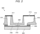
- a pipette tip is inserted into a pipette tip insertion portion 3101 illustrated in Fig. 2 , and the liquid is dispensed into the pipette tip insertion portion 3101.
- an insertion hole hermetic seal 3111 is attached to the opening of the pipette tip insertion portion 3101, and the pipette tip is inserted into the pipette tip insertion portion 3101 through the insertion hole hermetic seal 3111 at the liquid delivery, and the pipette tip insertion portion 3101 is hermetically sealed by bringing the pipette tip into close contact with the insertion hole hermetic seal 3111.
- the air in the pipette tip insertion portion 3101 is compressed to increase the air pressure in the pipette tip insertion portion 3101, making it possible to deliver the liquid to the microchannel.
- the air in the pipette tip insertion portion 3101 expands to decrease the air pressure in the pipette tip insertion portion 3101, so as to allow the liquid to return from the microchannel.
- the distance between the liquid dispensation port of the pipette tip and a conductor film (gold film) to be a bottom surface of the microchannel greatly influences the residual liquid amount in the channel after the liquid collection, and greatly affects the measurement result.
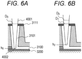
- a liquid dispensation port 4002 of the pipette tip is inserted into the end detection position h0 on the surface of or in the vicinity of the conductor film 3200.
- This end detection causes the diameter of the hole of the insertion hole hermetic seal 3111 through which the pipette tip 4001 has penetrated to be increased to the diameter D0. Accordingly, it is difficult, with an outer diameter D1 (smaller than diameter D0) at the position of the insertion hole hermetic seal of the pipette tip 4001 arranged at the sealed position h2, to close the hole of the insertion hole hermetic seal 3111 through which the pipette tip 4001 has penetrated, making it difficult to close the hole of the insertion hole hermetic seal 3111. This leads to difficulty in hermetically sealing the pipette tip insertion portion 3101 and difficulty in sufficiently supplying the liquid to the microchannel 3100.
- the diameter of the hole of the insertion hole hermetic seal 3111 does not necessarily stay at the diameter D0 penetrated by the pipette tip at the end detection when the liquid dispensation port 4002 of the pipette tip is arranged at the sealed position h2 (hereinafter, at the time of liquid delivery after the end detection) depending on the material characteristics of an elastic sheet described below used for the insertion hole hermetic seal 3111.
- the opening of the pipette tip insertion portion 3101 is hermetically sealed as illustrated in Fig. 8B after the pipette tip 4001 is brought into close contact with the insertion hole hermetic seal 3111.
- pressure would be applied to the inside of the pipette tip insertion portion 3101 and would cause the residual liquid 10 in the previous step to be pushed out to the downstream side of the microchannel 3100.
- liquid is kept dispensing at this state as illustrated in Fig.
- Fig. 1 is a schematic diagram illustrating a configuration of a biochemical testing apparatus.
- the measurement unit 2300 includes a photomultiplier tube as a light receiving element and is arranged on an optical path of surface plasmon excitation fluorescence 9200 and measures light amounts of the surface plasmon excitation fluorescence 9200 and scattered light 9300.
- the light amount of the surface plasmon excitation fluorescence 9200 is used to determine the presence or absence of binding of the target antigen or the amount of binding of the target antigen.
- the light amount of the scattered light 9300 is used for detecting an incident angle ⁇ of the excitation light. In this case, the angle ⁇ as the incident angle that maximizes the light amount of the scattered light 9300 is detected as an enhancement angle ⁇ r.
- the incident angle ⁇ of the excitation light may be detected using the following photodiode 2200 as described below. In that case, there is no need to detect the enhancement angle ⁇ r using the light amount of the scattered light 9300.
- the photodiode 2200 is arranged on the optical path of reflected light 9400 of the excitation light 9000 to measure the light amount of the reflected light 9400. In this case, the resonance angle that minimizes the light amount of the reflected light 9400 is detected, so as to be used for specifying the incident angle ⁇ of the excitation light.
- the photodiode 2200 may be omitted and replaced by a light absorber or the like.
- the control arithmetic unit 5000 includes a control arithmetic block group that controls operation of each of the above-described components.
- a bottom surface of the analysis chip 3000 includes a conductor film 3200 and a prism 3400 provided for generating surface plasmon resonance.
- the conductor film 3200 is a thin film formed of gold.
- the conductor film 3200 may be formed of a metal such as silver, copper, aluminum, or an alloy containing these metals.
- the prism 3400 is a dielectric medium formed of a material transparent to the excitation light 9000.
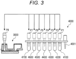
- the pump unit 2500 raises the pipette tip 4001, moves the pipette tip 4001 to a position P8 above the pipette tip insertion portion 3101 of the analysis chip 3000, and inserts the pipette tip 4001 into the pipette tip insertion portion 3101.
- the insertion depth of the pipette tip 4001 into the pipette tip insertion portion 3101 at the time of liquid delivery is adjusted under the control of the control arithmetic unit 5000. The details of the procedure will be described below.
- the CPU controls the entire biochemical test.
- the excitation light controller 5300 controls emission of excitation light.
- the photodiode operation controller 5400 controls operation of the photodiode 2200.
- the conveyance mechanism controller 5500 controls the conveyance mechanism 2400 so as to convey the analysis chip 3000 between a reaction position B and a measurement position A described below.
- the biochemical test is a test method of capturing a target antigen as a detection target by a biochemical reaction, attaching a fluorescent label to the captured target antigen, and determining the presence or absence of the detection target, a captured amount, or the like, on the basis of the light amount of fluorescence from the attached fluorescent label.
- Fig. 5 is a flowchart illustrating a procedure of a biochemical test. Hereinafter, a procedure of a biochemical test will be described with reference to Fig. 5 .
- the pump unit 2500 lowers the pipette tip while dispensing the air, and brings the pipette tip close to the surface of the conductor film (gold film) 3200 being the bottom surface of the pipette tip insertion portion 3101.
- the pressure sensor of the pump unit 2500 detects the air pressure in the pipette tip.
- the air pressure in the pipette tip increases as the liquid dispensation port of the pipette tip approaches the conductor film 3200.
- the pipette tip end detector 5203 of the control arithmetic unit 5000 compares a registered value of the air pressure in the pipette tip in the vicinity of the conductor film surface registered beforehand with the measured value of an air pressure within the pipette tip detected by the pressure sensor of the pump unit 2500.
- the pipette tip end detector 5203 stores a vertical position of the liquid dispensation port of the pipette tip at that time as the end detection position h0, and then stops the descent of the pipette tip. At that time, the liquid dispensation port of the pipette tip is positioned on the surface or in the vicinity of the conductor film 3200.
- the outer diameter of the pipette tip at that time at the position of the insertion hole hermetic seal is defined as a diameter D0 (refer to Fig. 6A ).
- a secondary reaction for fluorescent labeling is performed (step S106).
- the fluorescent labeling liquid is supplied to the microchannel 3100.
- the fluorescent labeling liquid and the antigen capture membrane 3300 come into contact with each other, and the fluorescent labeling antibody contained in the fluorescent labeling liquid binds to the captured target antigen, so as to attach a fluorescent label to the captured target antigen.
- the fluorescent labeling liquid is collected from the microchannel 3100 to be stored in the waste liquid container 4700 of the reagent chip 4000. Thereafter, the washing liquid is supplied into the microchannel 3100, and the inside of the channel is washed (step S107) similarly to step S104.
- the enhanced electric field excites the fluorescent label attached to the target antigen captured by the antigen capture membrane 3300. From the excited fluorescent label, surface plasmon excitation fluorescence 9200 is emitted.
- the measurement unit 2300 measures the light amount of the surface plasmon excitation fluorescence 9200 and determines the presence or absence or the amount of binding of the target antigen.
- the pipette tip 4003 includes, at an end portion to be inserted into the pipette tip insertion portion 3101 at liquid delivery, a cylindrical intermediate portion 4003a having an equal outer diameter and a conical dispensation portion 4003b positioned closer to the liquid dispensation port side than the intermediate portion 4003a.
- the outer diameter of the cylindrical intermediate portion 4003a having an equal outer diameter is 2.6 mm. From the viewpoint of ensuring the rigidity of the pipette tip, it is preferable that the pipette tip 4003 is formed to have the outer diameter of the liquid dispensation port 4002 of 0.9 mm or more.
- the pipette tip is inserted up to the end detection position h0 as illustrated in Fig. 7A .
- the diameter of the hole of the insertion hole hermetic seal 3111 penetrating through the pipette tip is increased to the outer diameter D0 of the pipette tip at the position of the insertion hole hermetic seal at that time.
- the liquid dispensation port of the pipette tip 4003 is arranged at the sealed position h2 when a liquid is supplied to the microchannel, as illustrated in Fig. 7B .
- the through hole is formed to be smaller than the outer diameter D1 of the pipette tip at the insertion hole hermetic seal when arranged at the sealed position in order to ensure the sealability at the time of liquid delivery as described above.
- the pipette tip 4003 penetrates through the encapsulating seal to be inserted into the washing liquid container 4100, the dilution container 4300, the liquid sample container 4400, the fluorescent labeling liquid container 4500, the measurement liquid container 4600, or the waste liquid container 4700. At that time, a hole through which the pipette tip 4003 has penetrated is opened in the encapsulating seal. When the hole through which the pipette tip 4003 has penetrated is widely opened in the encapsulating seal, the liquid contained in each of the liquid containers 4100, and 4300 to 4700 might spill.
- the pipette tip 4001 is first inserted into a comparatively shallow ventilation position h1 so as not to seal the pipette tip insertion portion 3101.
- This configuration ensures an air escape between the pipette tip 4001 and the insertion hole hermetic seal 3111.
- a first amount of liquid is dispensed at this ventilation position h1. In this state, since the air escape is ensured in this state, dispensation of the liquid would apply no pressure to the inside of the pipette tip insertion portion 3101, and thus, the residual liquid 10 in the preceding step is not pushed out toward the downstream side of the microchannel 3100.
- the insertion hole hermetic seal 3111 extends to the inside of the pipette tip insertion portion 3101 to form an extending portion. In this case, it is possible to prevent interference of the extending portion with liquid dispensation from the liquid dispensation port 4002 by arranging the liquid dispensation port 4002 of the pipette tip 4003 to be positioned below the extending portion.
Landscapes
- Chemical & Material Sciences (AREA)
- Health & Medical Sciences (AREA)
- General Health & Medical Sciences (AREA)
- Analytical Chemistry (AREA)
- Physics & Mathematics (AREA)
- Immunology (AREA)
- Pathology (AREA)
- Biochemistry (AREA)
- Life Sciences & Earth Sciences (AREA)
- General Physics & Mathematics (AREA)
- Chemical Kinetics & Catalysis (AREA)
- Clinical Laboratory Science (AREA)
- Dispersion Chemistry (AREA)
- Hematology (AREA)
- Nuclear Medicine, Radiotherapy & Molecular Imaging (AREA)
- Optics & Photonics (AREA)
- Automatic Analysis And Handling Materials Therefor (AREA)
- Optical Measuring Cells (AREA)
- Investigating, Analyzing Materials By Fluorescence Or Luminescence (AREA)
Claims (7)
- Ein Testbausatz, der einen Analysechip (3000) und eine Pipettenspitze (4001) aufweist,wobei der Analysechip (3000) einen Pipettenspitzen-Einführabschnitt (3101) umfasst, der durch eine Dichtung (3111) hermetisch abdichtbar ist, und einen Mikrokanal (3100) umfasst, der mit einer Bodenoberfläche des Pipettenspitzen-Einführabschnitts (3101) verbunden ist,ein Endabschnitt der Pipettenspitze (4001), der in den Pipettenspitzen-Einführabschnitt (3101) einzuführen ist, umfasst: einen ersten Abschnitt, der konfiguriert ist, um in Kontakt mit der Dichtung (3111) zu sein,dadurch gekennzeichnet, dass der Endabschnitt der Pipettenspitze (4001) ferner umfasst: einen zweiten Abschnitt, der näher an der Seite der Flüssigkeitsabgabeöffnung (4002) positioniert ist als der erste Abschnitt, undein Außendurchmesser des zweiten Abschnitts so ausgebildet ist, dass er größer ist als ein Außendurchmesser des ersten Abschnitts und irgendeines Abschnitts zwischen dem ersten Abschnitt und dem zweiten Abschnitt,wobei der Endabschnitt der Pipettenspitze (4001), der in den Pipettenspitzen-Einführabschnitt (3101) einzuführen ist, ferner einen dritten Abschnitt mit einem Außendurchmesser umfasst, der kleiner ist als der Außendurchmesser des ersten Abschnitts, wobei der dritte Abschnitt näher an der Seite der Flüssigkeitsabgabeöffnung (4002) positioniert ist als der zweite Abschnitt und der dritte Abschnitt eine Trichterform aufweist, undwobei die Dichtung (3111) ein Durchgangsloch aufweist, wobei das Durchgangsloch einen Durchmesser aufweist, der kleiner ist als ein Außendurchmesser eines Abschnitts des zweiten Abschnitts des Endabschnitts der Pipettenspitze (4001), der in den Pipettenspitzen-Einführabschnitt (3101) einzuführen ist, und wobei das Durchgangsloch einen Durchmesser aufweist, der größer ist als der dritte Abschnitt der Pipettenspitze (4001).
- Der Testbausatz nach Anspruch 1,
wobei der Endabschnitt der Pipettenspitze (4001), der in den Pipettenspitzen-Einführabschnitt (3101) einzuführen ist, in einer zylindrischen Form ausgebildet ist, wobei ein Abschnitt von dem ersten Abschnitt bis zu dem zweiten Abschnitt einen gleichen Außendurchmesser aufweist. - Der Testbausatz nach Anspruch 2,
wobei in dem Endabschnitt der Pipettenspitze (4001), der in den Pipettenspitzen-Einführabschnitt (3101) einzuführen ist, ein Abschnitt, der näher an der Seite der Flüssigkeitsabgabeöffnung (4002) liegt als der zweite Abschnitt, Folgendes umfasst:einen ersten Kegelstumpf mit einem Außendurchmesser, der mit einer konstanten ersten Abnahmerate in Richtung der Flüssigkeitsabgabeöffnung (4002) abnimmt; undeinen zweiten Kegelstumpf mit einem Außendurchmesser, der sich mit einer zweiten Abnahmerate ändert, die kleiner ist als die erste Abnahmerate, wobei der zweite Kegelstumpf kontinuierlich aus dem ersten Kegelstumpf ausgebildet ist, undder dritte Abschnitt an dem zweiten Kegelstumpf positioniert ist. - Der Testbausatz nach einem der Ansprüche 1 bis 3,
wobei die Flüssigkeitsabgabeöffnung (4002) der Pipettenspitze (4001) so ausgebildet ist, dass sie einen Außendurchmesser von 0,9 mm oder mehr aufweist. - Ein Verfahren zur Flüssigkeitsabgabe unter Verwendung eines Testbausatzes nach Anspruch 1, wobei das Verfahren zur Flüssigkeitsabgabe aufweist:einen ersten Schritt zum Einführen der Pipettenspitze (4001) in den Pipettenspitzen-Einführabschnitt (3101), so dass die Flüssigkeitsabgabeöffnung (4002) der Pipettenspitze (4001) an oder in der Umgebung der Bodenoberfläche des Pipettenspitzen-Einführabschnitts (3101) positioniert werden kann; undeinen zweiten Schritt zum Anordnen des zweiten Abschnitts der Pipettenspitze (4001), so dass er nach dem ersten Schritt in engem Kontakt mit der Dichtung (3111) steht, und zum Abgeben einer Flüssigkeit in den Pipettenspitzen-Einführabschnitt (3101), um die Flüssigkeit in den Mikrokanal (3100) zuzuführen.
- Ein Verfahren zur Flüssigkeitsabgabe unter Verwendung eines Testbausatzes nach Anspruch 1, wobei das Verfahren zur Flüssigkeitsabgabe aufweist:einen ersten Schritt zum Zuführen einer ersten Flüssigkeit in den Mikrokanal (3100);einen zweiten Schritt zum Sammeln der ersten in den Mikrokanal (3100) zugeführten Flüssigkeit aus dem Inneren des Mikrokanals (3100);einen dritten Schritt zum Abgeben einer ersten Menge einer zweiten Flüssigkeit in den Pipettenspitzen-Einführabschnitt (3101) in einem Zustand, in dem der dritte Abschnitt der Pipettenspitze (4001) an einer Position der Dichtung (3111) angeordnet ist; undeinen vierten Schritt zum Anordnen des zweiten Abschnitts der Pipettenspitze (4001), so dass er nach dem Abgeben der ersten Menge der zweiten Flüssigkeit in engem Kontakt mit der Dichtung (3111) steht, und dann zum Abgeben einer zweiten Menge der zweiten Flüssigkeit in den Pipettenspitzen-Einführabschnitt (3101), um die zweite Flüssigkeit in den Mikrokanal (3100) zuzuführen.
- Eine Testvorrichtung, aufweisend:einen Testbausatz nach Anspruch 1, der entfernbar installierbar ist;einen Flüssigkeitszuführabschnitt, der eine Flüssigkeitszuführeinrichtung zum Zuführen einer Flüssigkeit von der in den Pipettenspitzen-Einführabschnitt (3101) eingeführten Pipettenspitze (4001) in den Mikrokanal (3100) ist, wobei die Flüssigkeitszuführeinrichtung eine erste Flüssigkeit in den Mikrokanal (3100) zuführt, die die in den Mikrokanal (3100) zugeführte erste Flüssigkeit aus dem Inneren des Mikrokanals (3100) sammelt und danach eine erste Menge einer zweiten Flüssigkeit in den Pipettenspitzen-Einführabschnitt (3101) in einem Zustand abgibt, in dem der dritte Abschnitt der Pipettenspitze (4001) an einer Position der Dichtung (3111) angeordnet ist, Anordnen des zweiten Abschnitts der Pipettenspitze (4001), so dass er nach dem Abgeben der ersten Menge der zweiten Flüssigkeit in engem Kontakt mit der Dichtung (3111) steht, und dann Abgeben einer zweiten Menge der zweiten Flüssigkeit in den Pipettenspitzen-Einführabschnitt (3101), um die zweite Flüssigkeit in den Mikrokanal (3100) zuzuführen; undeinen Detektor, der ein Reaktionsergebnis eines Reaktionsfeldes erfasst, das innerhalb des Mikrokanals (3100) fixiert ist.
Applications Claiming Priority (2)
| Application Number | Priority Date | Filing Date | Title |
|---|---|---|---|
| JP2015224215 | 2015-11-16 | ||
| PCT/JP2016/082958 WO2017086199A1 (ja) | 2015-11-16 | 2016-11-07 | 検査キット、検査キットを使用した送液方法及び検査装置 |
Publications (3)
| Publication Number | Publication Date |
|---|---|
| EP3379256A1 EP3379256A1 (de) | 2018-09-26 |
| EP3379256A4 EP3379256A4 (de) | 2018-11-14 |
| EP3379256B1 true EP3379256B1 (de) | 2025-04-16 |
Family
ID=58718855
Family Applications (1)
| Application Number | Title | Priority Date | Filing Date |
|---|---|---|---|
| EP16866201.3A Active EP3379256B1 (de) | 2015-11-16 | 2016-11-07 | Testkit, flüssigkeitsabgabeverfahren und testvorrichtung mit dem testkit |
Country Status (5)
| Country | Link |
|---|---|
| US (1) | US11333674B2 (de) |
| EP (1) | EP3379256B1 (de) |
| JP (1) | JP6737285B2 (de) |
| ES (1) | ES3030511T3 (de) |
| WO (1) | WO2017086199A1 (de) |
Families Citing this family (5)
| Publication number | Priority date | Publication date | Assignee | Title |
|---|---|---|---|---|
| CN112601807B (zh) * | 2018-08-30 | 2024-11-29 | 国立研究开发法人产业技术综合研究所 | Pcr反应容器 |
| CN109821585A (zh) * | 2019-02-19 | 2019-05-31 | 苏州奥素液芯电子科技有限公司 | 数字微流控系统中滴液加样或取样方法、移液器吸头组件 |
| GB201902810D0 (en) * | 2019-03-01 | 2019-04-17 | Vidya Holdings Ltd | Disposition of reagents in assay device |
| CN113083388B (zh) * | 2021-04-26 | 2022-10-25 | 苏州德运康瑞生物科技有限公司 | 一种血液细胞捕获染色仪的芯片自动对接装置 |
| BR102023003038A2 (pt) * | 2022-03-17 | 2024-01-02 | Sysmex Corporation | Método para classificar glóbulos brancos em subpopulações |
Family Cites Families (23)
| Publication number | Priority date | Publication date | Assignee | Title |
|---|---|---|---|---|
| JPS5357894U (de) | 1976-10-15 | 1978-05-17 | ||
| US4917274A (en) * | 1983-09-27 | 1990-04-17 | Maurice Asa | Miniscule droplet dispenser tip |
| US4971763A (en) | 1989-02-14 | 1990-11-20 | Eastman Kodak Company | Liquid-controlling nozzle geometry for dispensers of liquids |
| DE19643320A1 (de) * | 1996-10-21 | 1998-04-23 | Boehringer Mannheim Gmbh | System zur kontaminationsfreien Bearbeitung von thermischen Reaktionsprozessen |
| FR2767583B1 (fr) | 1997-08-20 | 1999-10-22 | Junior Instruments | Dispositif pour le prelevement et/ou l'injection a l'interieur d'un tube d'echantillon bouche |
| US6273478B1 (en) * | 1999-03-30 | 2001-08-14 | The Regents Of The University Of California | Microfluidic interconnects |
| US20040017078A1 (en) | 2002-04-02 | 2004-01-29 | Karp Christoph D. | Connectors for microfluidic devices |
| US20030157503A1 (en) * | 2003-04-04 | 2003-08-21 | Mcgarry Mark W | Compositions and methods for performing biological reactions |
| GB0505378D0 (en) | 2005-03-16 | 2005-04-20 | Robio Systems Ltd | Fluidic devices for cell and embryo culture |
| SE528638C2 (sv) * | 2005-04-08 | 2007-01-09 | Boule Medical Ab | Anordning för fyllning av en enhet för bestämning av en provvolym |
| JP5129729B2 (ja) * | 2008-02-08 | 2013-01-30 | 富士フイルム株式会社 | ピペットチップ |
| CA2723707C (en) | 2008-05-09 | 2016-08-23 | Akonni Biosystems | Microarray system |
| WO2011026128A2 (en) | 2009-08-31 | 2011-03-03 | Life Technologies Corporation | Flowcells and methods of filling and using same |
| FR2969128B1 (fr) | 2010-12-21 | 2012-12-28 | Bio Rad Pasteur | Bouchon pour fermer un recipient |
| EP2672273B1 (de) | 2011-01-31 | 2018-08-15 | Konica Minolta, Inc. | Inspektionschip und mit dem inspektionschip ausgestatteter inspektionschipsatz |
| WO2012160923A1 (ja) | 2011-05-23 | 2012-11-29 | コニカミノルタホールディングス株式会社 | 反応進行装置、交換製品及び交換製品の製造方法 |
| JP5870716B2 (ja) | 2012-01-31 | 2016-03-01 | コニカミノルタ株式会社 | 生化学検査装置 |
| JP6197263B2 (ja) | 2012-02-06 | 2017-09-20 | ソニー株式会社 | マイクロチップ |
| JP2013185967A (ja) | 2012-03-08 | 2013-09-19 | Konica Minolta Inc | 生化学検査装置 |
| JP6275121B2 (ja) | 2012-05-04 | 2018-02-07 | シーメンス・ヘルスケア・ダイアグノスティックス・インコーポレーテッドSiemens Healthcare Diagnostics Inc. | サンプル導入システム |
| JP5692164B2 (ja) | 2012-05-22 | 2015-04-01 | ウシオ電機株式会社 | マイクロチップへの試薬供給方法及びマイクロチップへの試薬供給装置 |
| WO2014047365A1 (en) * | 2012-09-19 | 2014-03-27 | Bio-Rad Laboratories, Inc. | Fluid transport system with gasket |
| JP6372985B2 (ja) | 2013-09-24 | 2018-08-15 | ウシオ電機株式会社 | マイクロチップおよびマイクロチップの製造方法 |
-
2016
- 2016-11-07 EP EP16866201.3A patent/EP3379256B1/de active Active
- 2016-11-07 US US15/775,278 patent/US11333674B2/en active Active
- 2016-11-07 JP JP2017551821A patent/JP6737285B2/ja active Active
- 2016-11-07 ES ES16866201T patent/ES3030511T3/es active Active
- 2016-11-07 WO PCT/JP2016/082958 patent/WO2017086199A1/ja not_active Ceased
Also Published As
| Publication number | Publication date |
|---|---|
| WO2017086199A1 (ja) | 2017-05-26 |
| ES3030511T3 (en) | 2025-06-30 |
| JP6737285B2 (ja) | 2020-08-05 |
| JPWO2017086199A1 (ja) | 2018-08-30 |
| EP3379256A1 (de) | 2018-09-26 |
| US11333674B2 (en) | 2022-05-17 |
| US20180372767A1 (en) | 2018-12-27 |
| EP3379256A4 (de) | 2018-11-14 |
Similar Documents
| Publication | Publication Date | Title |
|---|---|---|
| JP5853961B2 (ja) | 検査チップを備えた検査チップセット | |
| US11333674B2 (en) | Test kit, liquid delivery method and testing apparatus using test kit | |
| US11061046B2 (en) | Liquid delivery method, liquid delivery apparatus and analyzer | |
| JP5545233B2 (ja) | 検査システム | |
| JP7638941B2 (ja) | 試薬カートリッジ | |
| WO2005103642A1 (ja) | 検体の分離と識別と分注方法とその装置及び解析装置 | |
| JPWO2009145172A1 (ja) | フローセル及び送液方法 | |
| JP2013185967A (ja) | 生化学検査装置 | |
| EP2894459A1 (de) | Vorrichtung zur identifikation und ausgabe von proben sowie verfahren zur identifikation und ausgabe von proben | |
| EP3492926B1 (de) | Pipettenspitze, flüssigkeitsabgabeverfahren und flüssigkeitsabgabesystem | |
| JP6690655B2 (ja) | 送液方法、ならびにこれを行う検出システムおよび検出装置 | |
| WO2016132945A1 (ja) | 反応方法および反応装置 | |
| JP6513926B2 (ja) | 分析用具、分析装置、それらを含む分析システム、および分析用具の開口を覆うシート状部材の穿孔方法 | |
| JP7784473B2 (ja) | 流路デバイス | |
| JPWO2017221775A1 (ja) | 反応方法、ならびにこれを行う反応システムおよび反応装置 | |
| JP2011137676A (ja) | 分注装置,自動分析装置、および液量測定方法 | |
| WO2020009838A1 (en) | Fluidic channel for a cartridge | |
| JP5507991B2 (ja) | アプリケータ | |
| WO2025192216A1 (ja) | 分注装置及び検査装置 | |
| WO2025192215A1 (ja) | 分注装置及び検査装置 | |
| HK40075592A (en) | Reagent cartridge |
Legal Events
| Date | Code | Title | Description |
|---|---|---|---|
| STAA | Information on the status of an ep patent application or granted ep patent |
Free format text: STATUS: THE INTERNATIONAL PUBLICATION HAS BEEN MADE |
|
| PUAI | Public reference made under article 153(3) epc to a published international application that has entered the european phase |
Free format text: ORIGINAL CODE: 0009012 |
|
| STAA | Information on the status of an ep patent application or granted ep patent |
Free format text: STATUS: REQUEST FOR EXAMINATION WAS MADE |
|
| 17P | Request for examination filed |
Effective date: 20180411 |
|
| AK | Designated contracting states |
Kind code of ref document: A1 Designated state(s): AL AT BE BG CH CY CZ DE DK EE ES FI FR GB GR HR HU IE IS IT LI LT LU LV MC MK MT NL NO PL PT RO RS SE SI SK SM TR |
|
| AX | Request for extension of the european patent |
Extension state: BA ME |
|
| A4 | Supplementary search report drawn up and despatched |
Effective date: 20181017 |
|
| RIC1 | Information provided on ipc code assigned before grant |
Ipc: B01L 3/00 20060101AFI20181010BHEP Ipc: B01L 3/02 20060101ALI20181010BHEP Ipc: G01N 35/08 20060101ALI20181010BHEP Ipc: G01N 35/10 20060101ALI20181010BHEP |
|
| DAV | Request for validation of the european patent (deleted) | ||
| DAX | Request for extension of the european patent (deleted) | ||
| STAA | Information on the status of an ep patent application or granted ep patent |
Free format text: STATUS: EXAMINATION IS IN PROGRESS |
|
| 17Q | First examination report despatched |
Effective date: 20211029 |
|
| RAP1 | Party data changed (applicant data changed or rights of an application transferred) |
Owner name: OTSUKA PHARMACEUTICAL CO., LTD. |
|
| GRAP | Despatch of communication of intention to grant a patent |
Free format text: ORIGINAL CODE: EPIDOSNIGR1 |
|
| STAA | Information on the status of an ep patent application or granted ep patent |
Free format text: STATUS: GRANT OF PATENT IS INTENDED |
|
| INTG | Intention to grant announced |
Effective date: 20241112 |
|
| GRAS | Grant fee paid |
Free format text: ORIGINAL CODE: EPIDOSNIGR3 |
|
| GRAA | (expected) grant |
Free format text: ORIGINAL CODE: 0009210 |
|
| STAA | Information on the status of an ep patent application or granted ep patent |
Free format text: STATUS: THE PATENT HAS BEEN GRANTED |
|
| AK | Designated contracting states |
Kind code of ref document: B1 Designated state(s): AL AT BE BG CH CY CZ DE DK EE ES FI FR GB GR HR HU IE IS IT LI LT LU LV MC MK MT NL NO PL PT RO RS SE SI SK SM TR |
|
| REG | Reference to a national code |
Ref country code: GB Ref legal event code: FG4D |
|
| REG | Reference to a national code |
Ref country code: CH Ref legal event code: EP Ref country code: DE Ref legal event code: R096 Ref document number: 602016091947 Country of ref document: DE |
|
| REG | Reference to a national code |
Ref country code: IE Ref legal event code: FG4D |
|
| REG | Reference to a national code |
Ref country code: ES Ref legal event code: FG2A Ref document number: 3030511 Country of ref document: ES Kind code of ref document: T3 Effective date: 20250630 |
|
| P01 | Opt-out of the competence of the unified patent court (upc) registered |
Free format text: CASE NUMBER: APP_27202/2025 Effective date: 20250606 |
|
| REG | Reference to a national code |
Ref country code: NL Ref legal event code: MP Effective date: 20250416 |
|
| PG25 | Lapsed in a contracting state [announced via postgrant information from national office to epo] |
Ref country code: NL Free format text: LAPSE BECAUSE OF FAILURE TO SUBMIT A TRANSLATION OF THE DESCRIPTION OR TO PAY THE FEE WITHIN THE PRESCRIBED TIME-LIMIT Effective date: 20250416 |
|
| REG | Reference to a national code |
Ref country code: AT Ref legal event code: MK05 Ref document number: 1785224 Country of ref document: AT Kind code of ref document: T Effective date: 20250416 |
|
| PG25 | Lapsed in a contracting state [announced via postgrant information from national office to epo] |
Ref country code: PT Free format text: LAPSE BECAUSE OF FAILURE TO SUBMIT A TRANSLATION OF THE DESCRIPTION OR TO PAY THE FEE WITHIN THE PRESCRIBED TIME-LIMIT Effective date: 20250818 Ref country code: FI Free format text: LAPSE BECAUSE OF FAILURE TO SUBMIT A TRANSLATION OF THE DESCRIPTION OR TO PAY THE FEE WITHIN THE PRESCRIBED TIME-LIMIT Effective date: 20250416 |
|
| REG | Reference to a national code |
Ref country code: LT Ref legal event code: MG9D |
|
| PG25 | Lapsed in a contracting state [announced via postgrant information from national office to epo] |
Ref country code: GR Free format text: LAPSE BECAUSE OF FAILURE TO SUBMIT A TRANSLATION OF THE DESCRIPTION OR TO PAY THE FEE WITHIN THE PRESCRIBED TIME-LIMIT Effective date: 20250717 Ref country code: NO Free format text: LAPSE BECAUSE OF FAILURE TO SUBMIT A TRANSLATION OF THE DESCRIPTION OR TO PAY THE FEE WITHIN THE PRESCRIBED TIME-LIMIT Effective date: 20250716 |
|
| PG25 | Lapsed in a contracting state [announced via postgrant information from national office to epo] |
Ref country code: PL Free format text: LAPSE BECAUSE OF FAILURE TO SUBMIT A TRANSLATION OF THE DESCRIPTION OR TO PAY THE FEE WITHIN THE PRESCRIBED TIME-LIMIT Effective date: 20250416 |
|
| PG25 | Lapsed in a contracting state [announced via postgrant information from national office to epo] |
Ref country code: BG Free format text: LAPSE BECAUSE OF FAILURE TO SUBMIT A TRANSLATION OF THE DESCRIPTION OR TO PAY THE FEE WITHIN THE PRESCRIBED TIME-LIMIT Effective date: 20250416 |
|
| PG25 | Lapsed in a contracting state [announced via postgrant information from national office to epo] |
Ref country code: HR Free format text: LAPSE BECAUSE OF FAILURE TO SUBMIT A TRANSLATION OF THE DESCRIPTION OR TO PAY THE FEE WITHIN THE PRESCRIBED TIME-LIMIT Effective date: 20250416 |
|
| PG25 | Lapsed in a contracting state [announced via postgrant information from national office to epo] |
Ref country code: AT Free format text: LAPSE BECAUSE OF FAILURE TO SUBMIT A TRANSLATION OF THE DESCRIPTION OR TO PAY THE FEE WITHIN THE PRESCRIBED TIME-LIMIT Effective date: 20250416 |
|
| PG25 | Lapsed in a contracting state [announced via postgrant information from national office to epo] |
Ref country code: RS Free format text: LAPSE BECAUSE OF FAILURE TO SUBMIT A TRANSLATION OF THE DESCRIPTION OR TO PAY THE FEE WITHIN THE PRESCRIBED TIME-LIMIT Effective date: 20250716 |
|
| PG25 | Lapsed in a contracting state [announced via postgrant information from national office to epo] |
Ref country code: IS Free format text: LAPSE BECAUSE OF FAILURE TO SUBMIT A TRANSLATION OF THE DESCRIPTION OR TO PAY THE FEE WITHIN THE PRESCRIBED TIME-LIMIT Effective date: 20250816 |
|
| PG25 | Lapsed in a contracting state [announced via postgrant information from national office to epo] |
Ref country code: LV Free format text: LAPSE BECAUSE OF FAILURE TO SUBMIT A TRANSLATION OF THE DESCRIPTION OR TO PAY THE FEE WITHIN THE PRESCRIBED TIME-LIMIT Effective date: 20250416 |
|
| PGFP | Annual fee paid to national office [announced via postgrant information from national office to epo] |
Ref country code: DE Payment date: 20251124 Year of fee payment: 10 |
|
| PGFP | Annual fee paid to national office [announced via postgrant information from national office to epo] |
Ref country code: GB Payment date: 20251127 Year of fee payment: 10 |
|
| PG25 | Lapsed in a contracting state [announced via postgrant information from national office to epo] |
Ref country code: SM Free format text: LAPSE BECAUSE OF FAILURE TO SUBMIT A TRANSLATION OF THE DESCRIPTION OR TO PAY THE FEE WITHIN THE PRESCRIBED TIME-LIMIT Effective date: 20250416 Ref country code: DK Free format text: LAPSE BECAUSE OF FAILURE TO SUBMIT A TRANSLATION OF THE DESCRIPTION OR TO PAY THE FEE WITHIN THE PRESCRIBED TIME-LIMIT Effective date: 20250416 |
|
| PGFP | Annual fee paid to national office [announced via postgrant information from national office to epo] |
Ref country code: IT Payment date: 20251124 Year of fee payment: 10 |
|
| PGFP | Annual fee paid to national office [announced via postgrant information from national office to epo] |
Ref country code: FR Payment date: 20251127 Year of fee payment: 10 |
|
| REG | Reference to a national code |
Ref country code: DE Ref legal event code: R097 Ref document number: 602016091947 Country of ref document: DE |
|
| PG25 | Lapsed in a contracting state [announced via postgrant information from national office to epo] |
Ref country code: CZ Free format text: LAPSE BECAUSE OF FAILURE TO SUBMIT A TRANSLATION OF THE DESCRIPTION OR TO PAY THE FEE WITHIN THE PRESCRIBED TIME-LIMIT Effective date: 20250416 |
|
| PG25 | Lapsed in a contracting state [announced via postgrant information from national office to epo] |
Ref country code: EE Free format text: LAPSE BECAUSE OF FAILURE TO SUBMIT A TRANSLATION OF THE DESCRIPTION OR TO PAY THE FEE WITHIN THE PRESCRIBED TIME-LIMIT Effective date: 20250416 |
|
| PG25 | Lapsed in a contracting state [announced via postgrant information from national office to epo] |
Ref country code: SK Free format text: LAPSE BECAUSE OF FAILURE TO SUBMIT A TRANSLATION OF THE DESCRIPTION OR TO PAY THE FEE WITHIN THE PRESCRIBED TIME-LIMIT Effective date: 20250416 Ref country code: RO Free format text: LAPSE BECAUSE OF FAILURE TO SUBMIT A TRANSLATION OF THE DESCRIPTION OR TO PAY THE FEE WITHIN THE PRESCRIBED TIME-LIMIT Effective date: 20250416 |
|
| PGFP | Annual fee paid to national office [announced via postgrant information from national office to epo] |
Ref country code: ES Payment date: 20251223 Year of fee payment: 10 |
|
| PLBE | No opposition filed within time limit |
Free format text: ORIGINAL CODE: 0009261 |
|
| STAA | Information on the status of an ep patent application or granted ep patent |
Free format text: STATUS: NO OPPOSITION FILED WITHIN TIME LIMIT |
|
| REG | Reference to a national code |
Ref country code: CH Ref legal event code: L10 Free format text: ST27 STATUS EVENT CODE: U-0-0-L10-L00 (AS PROVIDED BY THE NATIONAL OFFICE) Effective date: 20260225 |
|
| 26N | No opposition filed |
Effective date: 20260119 |